R tron SNTRIDC Wireless Booster(CDMA) User Manual RSN TRI 25 24 DC 0314 indd
R-tron Inc. Wireless Booster(CDMA) RSN TRI 25 24 DC 0314 indd
R tron >
Contents
- 1. User Manual 1
- 2. User Manual 2
- 3. User Manual 3
User Manual 1

Notice
Trademark
R-tron is a registered trademark of R-tron Inc.
Other products and company names mentioned here in this manual might be
trademarks or trade names of their respective owners.
Copyright
Copyright © R-tron Inc. 2000-2008
All Rights Reserved
Any reproduction, distribution, or revisions of any or all portions of this manual is
prohibited without written permission from R-tron Inc.
Notice
This document describes the specifications, installation, and operation of the Tri
MINI.
Hardware and software mentioned in this document are subject to continuous
development and improvement. Consequently, there may be minor discrepancies
between the information in the document, performance, and design of the product.
Specifications, dimensions, and other statements mentioned in this document are
subject to change without notice.
Questions or Comments
Address: R-tron Inc. 6402 College Boulevard, Overland Park, KS 66211
Phone: +1-913-344-9977, 1-888-31R-TRON
Fax: +1-913-344-9988
e-mail: info@r-tron.com
Website: www.r-tron.com
1
User’s Manual
Safety Precautions
Safety Precautions
Warning
Opening the Tri MINI could result in electric shock and may cause severe injury.
Warning
Connect the equipment frame ground to building ground.
Warning
Operating the Tri MINI with antennas in very close proximity facing each other
could lead to severe damage to the repeater.
Caution
RF EXPOSURE INFORMATION
A minimum separation distance of 7.9 inches (20cm) must be maintained between
the user and the external antenna of repeater to satisfy FCC RF exposure
requirements. For more information about RF exposure, please visit the FCC
website at www.fcc.gov
Caution
This equipment is for indoor use and enables the communication wiring to
communicate only inside the building.

2
Contents
Glossary
1. Introduction
2. Description
2.1 Main Unit Overview
2.2 Sub Unit Overview
2.2.1 Block Diagrams
2.2.2 PSU (Power Supply Unit)
2.2.3 UDCs (Up Down Converter)
2.2.4 MCU (Main Control Unit)
2.2.5 HPAs (High Power Amplifiers)
2.2.6 Multiplexer
3. Hardware Installation
3.1 Check List of Items
3.1.1 Items
3.2 Mounting
3.3 Grounding
3.4 RF Cable Connection
3.5 Power On
4. Operation
4.1 Connections
4.2 System Requirements
4.3 Network Setup
4.3.1 Windows XP
4.3.2 Windows 2000
4.3.3 Windows Vista
4.4 System Login
4.5 System Setup
5. Troubleshooting
6. Specifications
7. Appendix
3
4
6
6
7
8
9
10
11
12
13
14
14
14
15
18
18
20
21
21
22
22
22
25
27
31
33
69
72
75

3
User’s Manual
Glossary
The following is a list of abbreviations and terms used in this manual.
Glossary
ALC (Automatic Level Control)
ALC feature prevents the repeater from exceeding its maximum output power by
reducing the gain automatically. ALC is used to adjust the gain to an appropriate
level for a range of input signal levels.
ASD (Automatic Shutdown)
Automatic shut down protects the repeater from the oscillation or excessive input
signal and eliminates any degradation to the network.
There are three parameters: ASD LEVEL, ASD TIME and ASD COUNT.
If the output power gets higher than “ASD LEVEL”, the repeater will shut down for
“ASD TIME” seconds and then it will turn the amp back on to measure the output
power again. If this repeats at “ASD COUNT” times, the repeater will shut down
completely.
Abbreviation
AC
ALC
ANT
ASD
DC
GND
GUI
iDEN
LED
PSU
RF
TEMP
VSWR
Definition
Alternating Current
Automatic Level Control
Antenna
Automatic Shutdown
Direct Current
Grounding
Graphic User Interface
Integrated Digital Enhanced Network
Light Emitting Diode
Power Supply Unit
Radio Frequency
Temperature
Voltage Standing Wave Ratio

4
Tri MINI repeater is used to fill out areas in iDEN and CDMA mobile systems, such
as base station fringe areas, business and industrial building, etc.
Tri MINI receives signals from a base station, amplifies and retransmits the signals
to mobile stations. Also it receives, amplifies and retransmits signals in the opposite
direction. Both directions are served simultaneously with the following features:
1. Introduction
a. iDEN
• 7MHz or 18MHz-bandwidth service @ 800MHz’s
• 5MHz-bandwidth service @ 900MHz’s
• Adjustable Band Edge @ 800MHz’s and 900MHz’s
• Roll Offs: 65dBc at 0.5MHz outside pass-band
• Remote Access and Control
• Easy and Quick Installation
- Web-based GUI
- Plug and Play – DHCP Server @ Local Port an DHCP Client @ Remote Port
- Easy Setup(Automatic)
- Isolation Detection
• Auto Level Control & Auto Shut Down
b. CDMA
• Programmable Bandwidth and Band
- 5, 10, 15, and 20MHz contiguous and non-contiguous segments
- Any Band Combination within 65MHz PCS Band [A, D, B, E, F, C, G]
- Three(3) 5MHz segments
• Remote Access and Control
• Easy and Quick Installation
- Web-based GUI
- Plug and Play – DHCP Server @ Local Port an DHCP Client @ Remote Port
- Easy Setup(Automatic)
- Isolation Detection
• Auto Level Control & Auto Shut Down
5
User’s Manual
1. Introduction
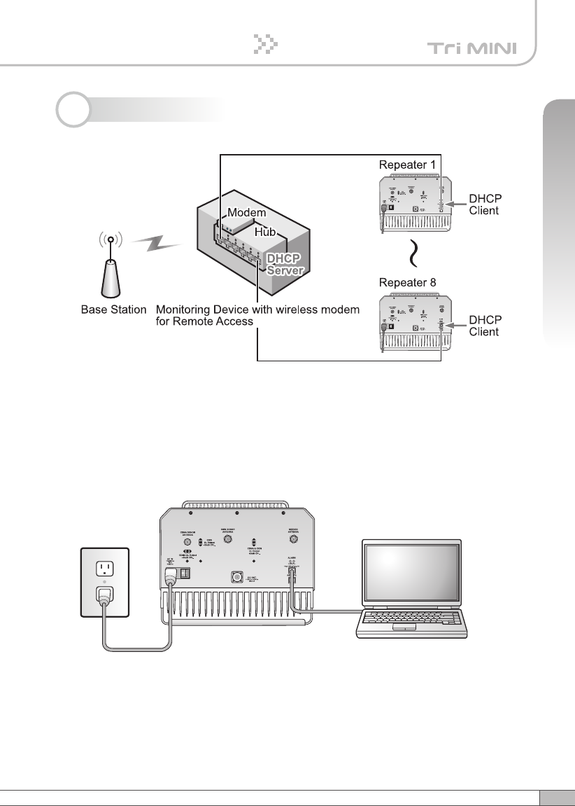
- TRI MINI utilizes the web-based user interface and web server to support the
remote access and control through an external monitoring device with wireless
modem. There are two physical RJ-45 ports:
• The Local port provides the on-site access to the repeater.
• The remote port allows remote users to access the repeater through an
external monitoring device.
The two ports allow local remote users to access the repeater simultaneously.
- DHCP server at the Local port enables Plug and Play by automatically assigning
the IP address to the user’s computer.
- Parameter setup is only one click away
• Easy setup feature will measure the isolation and limit the maximum gain
accordingly. This will also enable Auto Level Control as well as Auto Shut
Down. These two features are strongly recommended to prevent the
uncontrolled power output, which could have an adverse impact on the
RF network and the repeater. For example, ALC will automatically apply
attenuation when the input signal strength is increased due to the new base
station deployment near the repeater site.
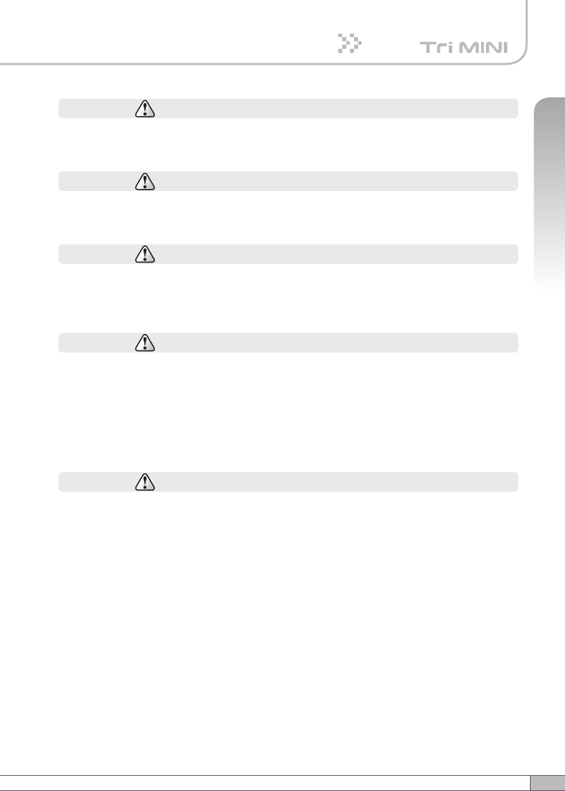
Tri MINI
Plugged in an
AC outlet
Base
Station
Mobile
Station
Donor antenna
for iDEN
Donor antenna
for CDMA
Service
Antenna
Tri MINI
Plugged in an
AC outlet
Base
Station
Mobile
Station
Donor antenna
for iDEN and CDMA
Service
Antenna
2Way
Divider
6
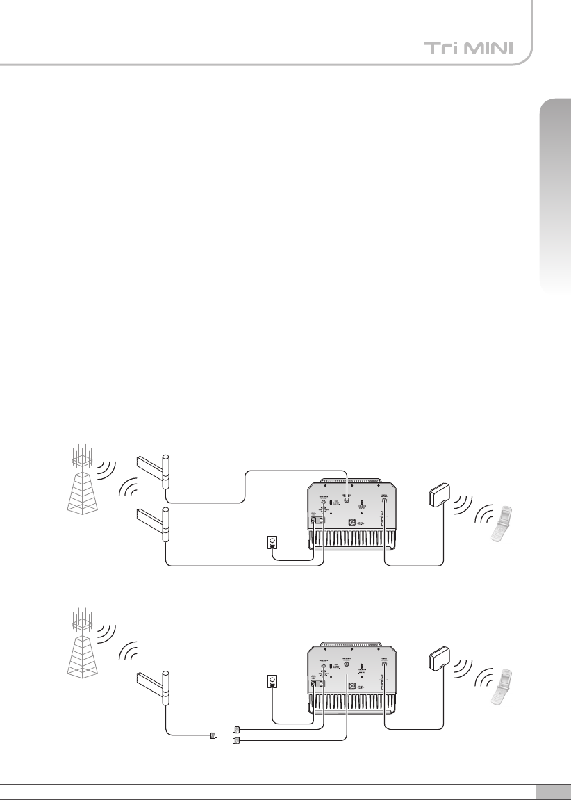
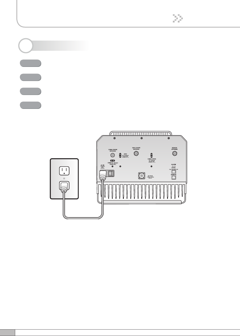
1. Ground Contact : Connects the repeater frame ground to the building ground.
2. AC In : AC power socket.
3. Switch : AC power switch.
4. CDMA Donor Antenna Port : Connects the donor antenna for CDMA.
5. iDEN Donor Antenna Port : Connects the donor antenna for iDEN.
6. Server Antenna Port : Connects the server antenna.
7. CDMA UL Output -30dB CPL : -30dB coupling port for UL output of CDMA.
8. iDEN UL Output -30dB CPL : -30dB coupling port for UL output of iDEN.
9. CDMA & iDEN DL Output -30dB CPL : -30dB coupling port for DL output.
10. Alarm LEDs : When the On site Alarm occurs, the red LED turns on. When
it operates normally, the green LED turns on. When it operates without any
problems, the green LED turns on.
11. • Local : This port provides on-site access to the repeater.
• Remote : This port allows remote users to access the repeater through an
external monitoring device.
The two ports allow local and remote users to access the repeater
simultaneously.
12. DC Out : Power outlet for compatible external devices only.
2.1 Main Unit Overview
DC Out
Alarm LEDs
Server
Antenna Port
CDMA & iDEN DL
Output -30dB CPL
Local Port
Remote Port
Ground Contact
AC IN
CDMA UL Output
-30dB CPL
iDEN UL Output
-30dB CPL
2. Description
Switch
CDMA Donor
Antenna Port
iDEN Donor
Antenna Port
7
User’s Manual
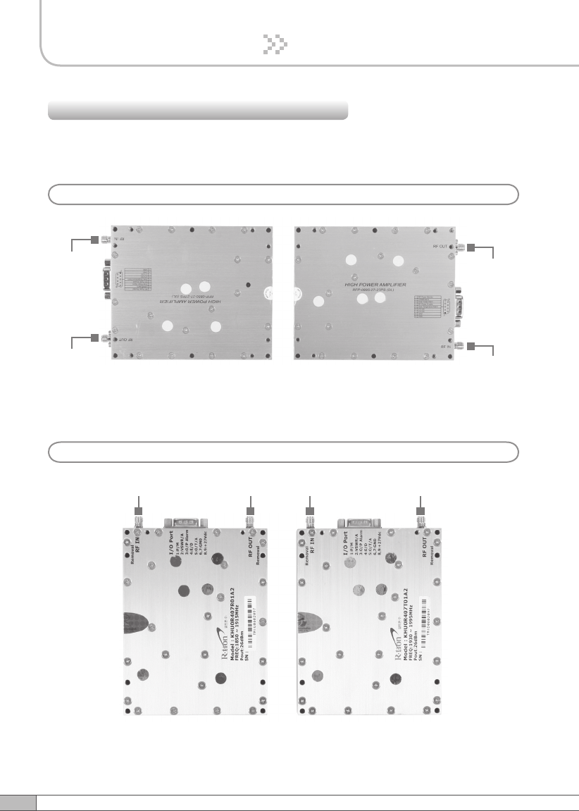
2. Description
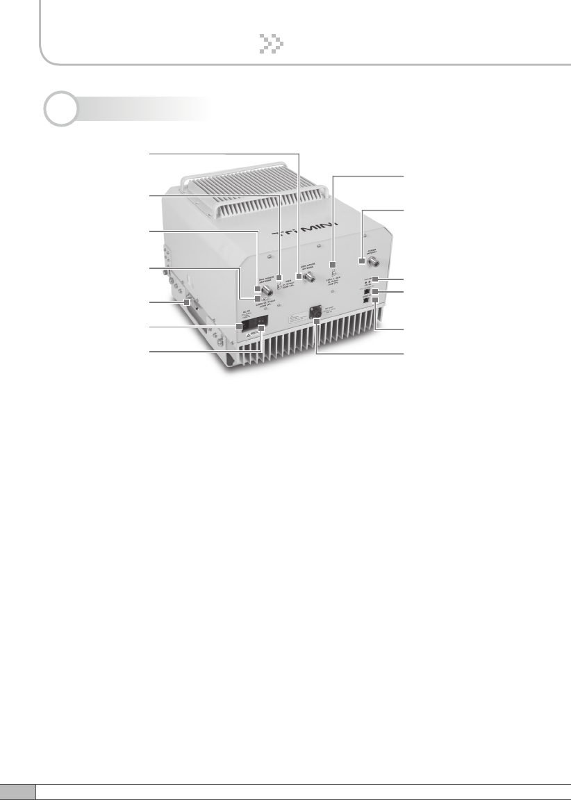
2.2 Sub Unit Overview
iDEN DL HPA
iDEN UDC
PSU
MCU
CDMA UDC
iDEN UL HPA
CDMA UL HPA
Multiplexer
CDMA DL HPA
8
2. Description
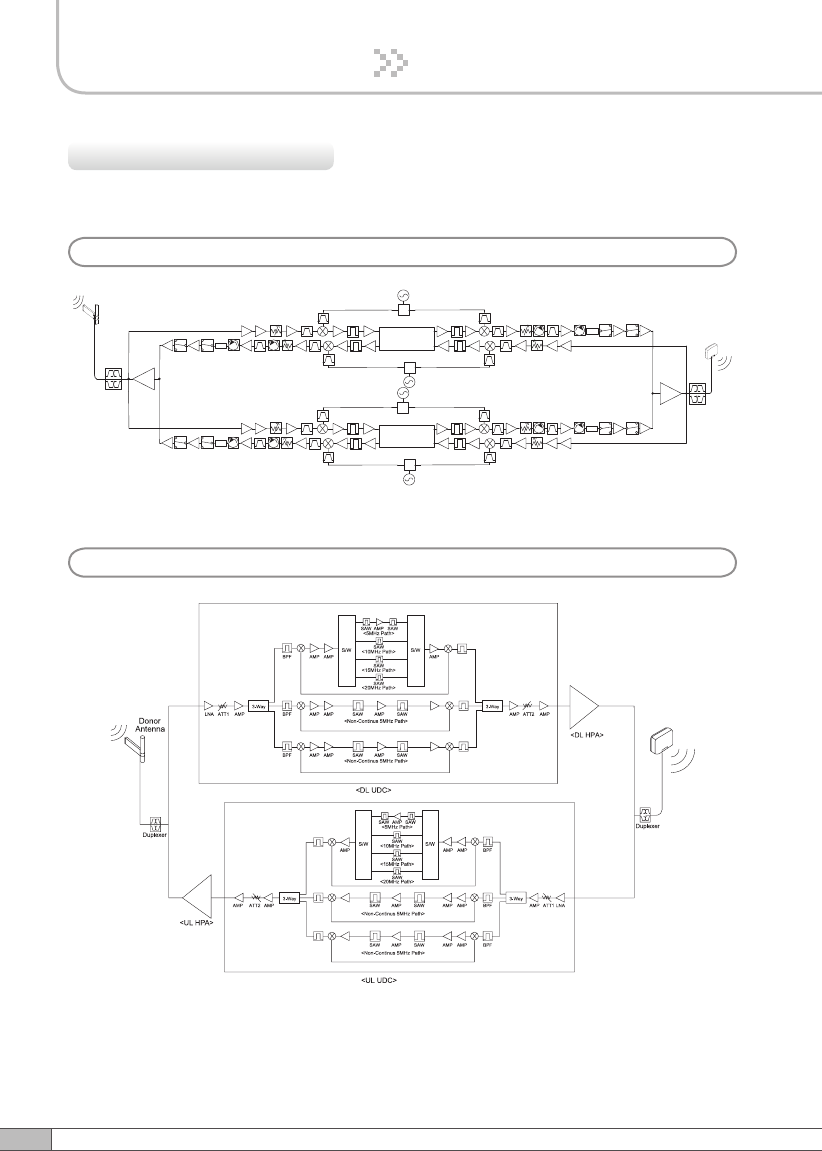
2.2.1 Block Diagrams
The following diagram explains how the Tri MINI serves signals.
Donor antena
RF switch
RF switch
RF switch
RF switch
RF switch
RF switch
RF switch RF switch
Divider
Divider
Divider
Divider
Divider
Divider
Divider
Divider
Is olator
Is olator
Is olator
Is olator
Is olator
Is olator
Is olator
Is olator
Multiplexer
UL
HPA
DL
HPA
Attenuator 2
Attenuator 2
Attenuator 1
Attenuator 1
Attenuator 2
Attenuator 2
Attenuator 1
Attenuator 1
Band Pass Filter
Band Pass Filter
Band Pass Filter
Band Pass Filter
Band Pass Filter
Band Pass Filter
Band Pass Filter
Band Pass Filter
Band Pass Filter
Band Pass Filter
Band Pass Filter
Band Pass Filter
SAW Filter
SAW Filter SAW Filter
SAW Filter
SAW Filter
SAW Filter
SAW Filter
SAW Filter
900 UL PLL
900 DL PLL
800 UL PLL
800 DL PLL
Multiplexer
Digital Filter
with Programmable options:
935~940/935~939.8/935~939.6MHz for downlink.
896~901/896~900.8/896~900.6MHz for upnlink.
Digital Filter
with Programmable options:
851~869/851~868.8/851~868.6MHz and
862~869/862~868.8/862~868.6MHz for downlink.
806~824/806~823.8/806~823.6MHz and
817~824/817~823.8/817~823.6MHz for upnlink.
Sever antenna
a. iDEN
b. CDMA
Server
Antenna
9
User’s Manual
2. Description
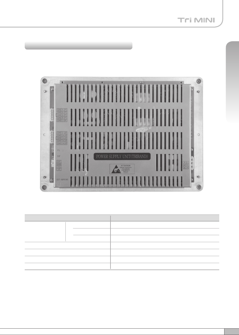
The PSU (Power Supply Unit) supplies a steady DC power to Tri MINI by drawing
power from the general in-wall AC outlets.
2.2.2 PSU (Power Supply Unit)
Specifications
-10˚C~50˚C (14˚F~122˚F)
20%~90%RH
Convection
AC110~125V
13A Max / 6.5V, 1A / 12V, 1A / -12V, 4A / 27VDC
50~60Hz typical
0.5mA max.@110V AC
Environmental
Operating Temp
Humidity
Cooling method
Voltage
Current
Frequency
Leakage Current
Item Specifications
10
2. Description
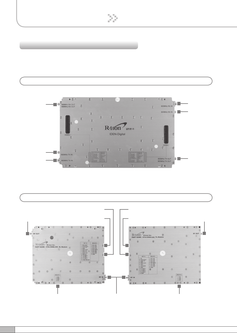
The UDCs(Up Down Converters) are basically bi-directional amplifiers that sharply
filters out unwanted noise.
2.2.3 UDCs (Up Down Converters)
900MHz
Downlink
Input Port
Uplink
Output
Port
800MHz
Uplink
Input Port
Downlink
Output
Port
900MHz
Uplink
Input Port
800MHz
Downlink
Input Port
a. iDEN
b. CDMA
RF OUT RF OUT
UL PLL
UL ATT DL ATT
DL PLL
RF INUL UDC DL UDC
11
User’s Manual
2. Description
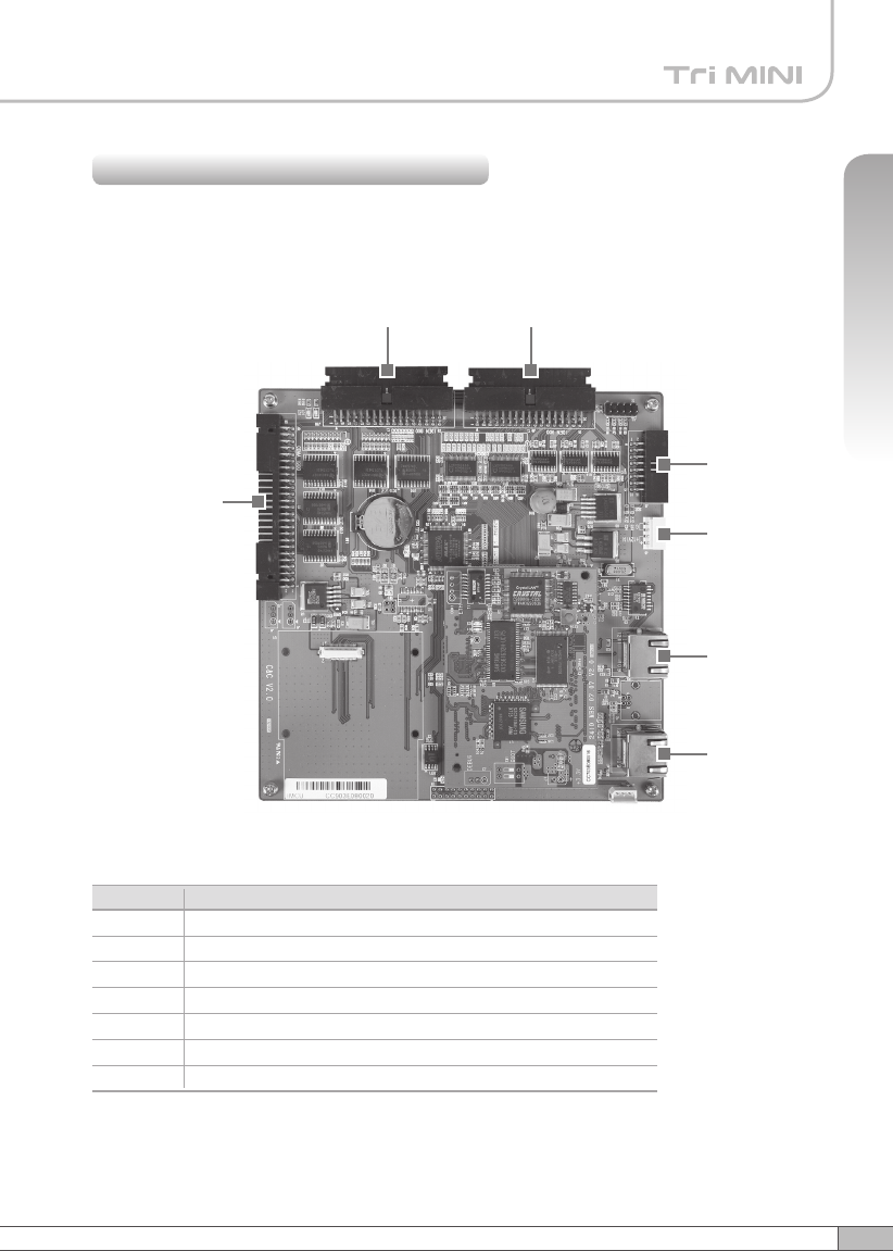
The MCU (Main Control Unit) is the control unit of Tri MINI. It controls and monitors
operational parameters. It is also responsible for generating an alarm, an event log
and many other functions of the Tri MINI.
Pin Map
2.2.4 MCU (Main Control Unit)
J4
J5
J6
J7
J1 J2
J3
Port Connected to
iDEN 800 PLL, B/S, OUT DET, DL(Tx)/UL(Rx) HPA
iDEN 900 PLL, B/S, OUT DET
CDMA UL, DL Control Pins
Alarms, LEDs
MCU Vcc(+12V)
Local Port
Remote Port
J1
J2
J3
J4
J5
J6
J7
12
2. Description
The HPAs (High Power Amplifiers) amplifies the transmitted signal from a base
station at the final stage of the repeater and vice versa.
2.2.5 HPAs (High Power Amplifiers)
RF Input
RF Output
RF Output
RF Input
a. iDEN
b. CDMA
RF Input RF Output RF Input RF Output
<UL HPA> <DL HPA>
<UL HPA> <DL HPA>
13
User’s Manual
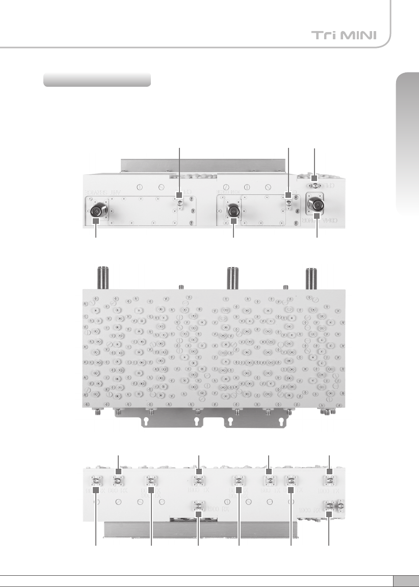
2. Description
A multiplexer is a device that combines two or more signals onto a common
channel or medium to increase its transmission efficiency.
2.2.6 Multiplexer
CDMA UL
Output
iDEN 800
DL Input
iDEN UL
Output
CDMA UL
Input
iDEN DL
Output
iDEN 900
UL Input
iDEN 800
UL Input
CDMA DL
Output
iDEN 800
DL Input
CDMA DL
Input
Server Antenna
Port
Donor Antenna
Port for iDEN
Donor Antenna
Port for CDMA
CDMA UL Output
-30dB CPL
iDEN UL Output
-30dB CPL
CDMA & iDEN DL
Output -30dB CPL
14
3. Hardware Installation
The installation procedure is as follows:
• Check List of Items
• Mounting
• Grounding
• RF Cable Connection
• Power On
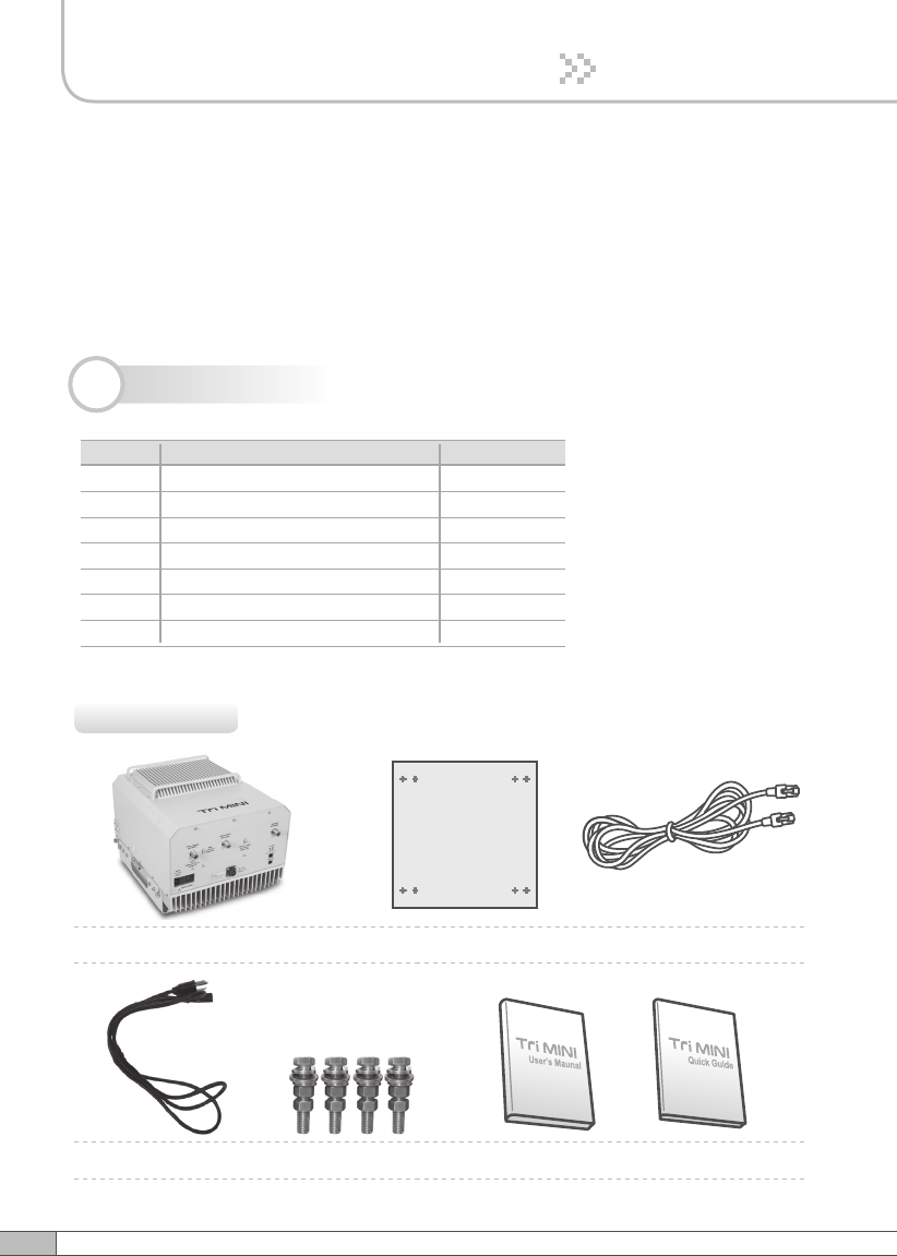
3.1 Check List of Items
Repeater
AC Cord Anchor Bolts
Wall Mounting Template UTP Cross LAN Cable
Quick GuideUser’s Manual
3.1.1 Items
Index Items
Repeater
AC Cord
Anchor Bolts
Wall Mounting Template
UTP Cross LAN Cable
Quick Guide
User’s Manual
1
2
3
4
5
6
7
Quantity
1
1
4
1
1
1
1
15
User’s Manual
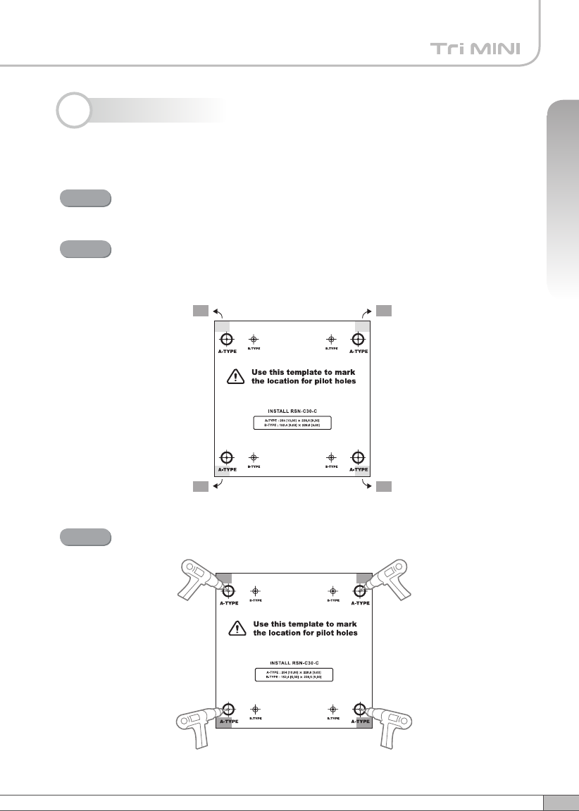
3. Hardware Installation
Tri MINI is easy to mount using the assembled mounting bracket, which has 9
holes for the provided 5/16” fixing screws.
3.2 Mounting
Remove the cover of double-coated foam tape squares at each corner
on the back side of the template.
Stick the provided template to the wall using the tape squares while
adjusting the horizon.
Mark the position for 4 screws depending on the installation location.
Step 1
Step 2
Drill holes directly through the template.
Step 3
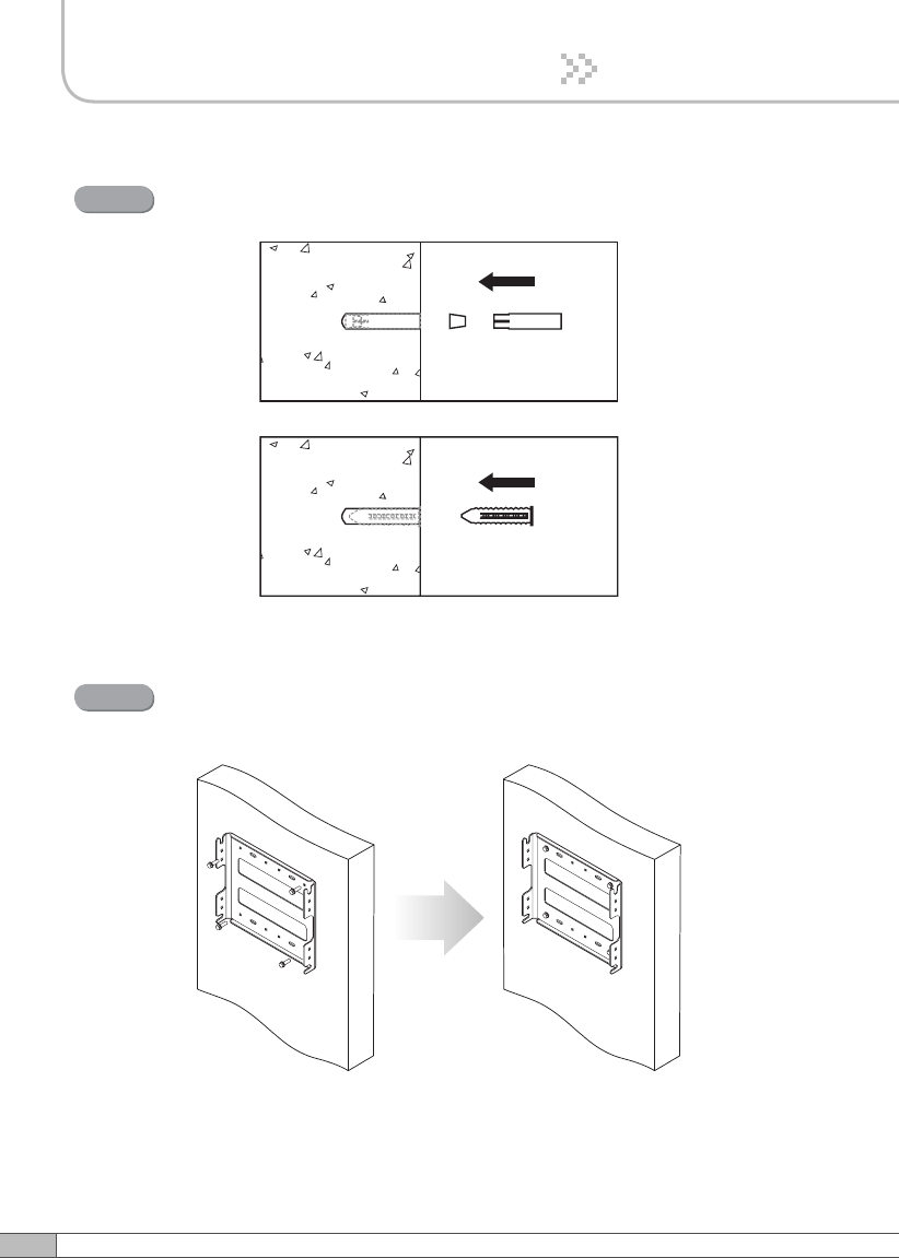
16
3. Hardware Installation
Install the set anchor bolts or the plastic anchor bolts on the holes.
Step 4
Attach the mounting bracket to the wall using provided bolts or extra
screws.
Step 5
17
User’s Manual
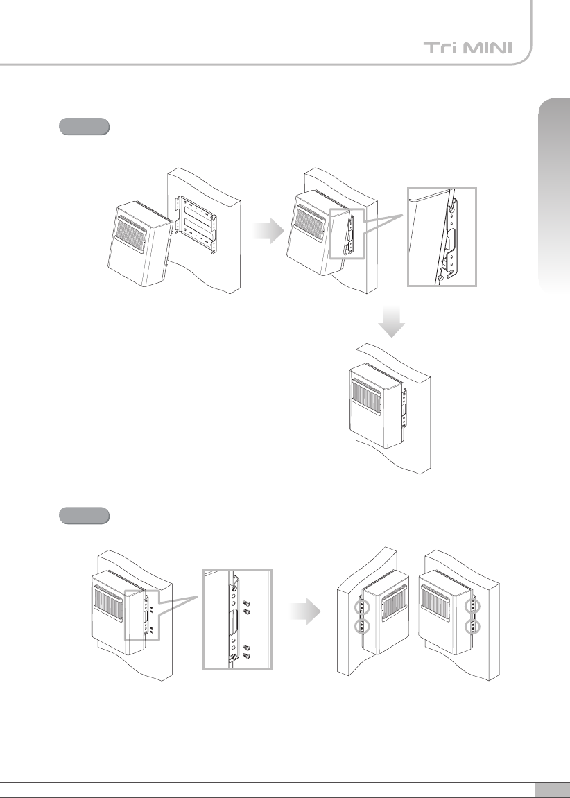
3. Hardware Installation
Lean the Tri MINI to hang the topside of the Guide Ring on the mounting
bracket, and push toward the wall to mount.
Step 6
Fix the Tri MINI using 8 screws provided.
Step 7
3. Hardware Installation
18
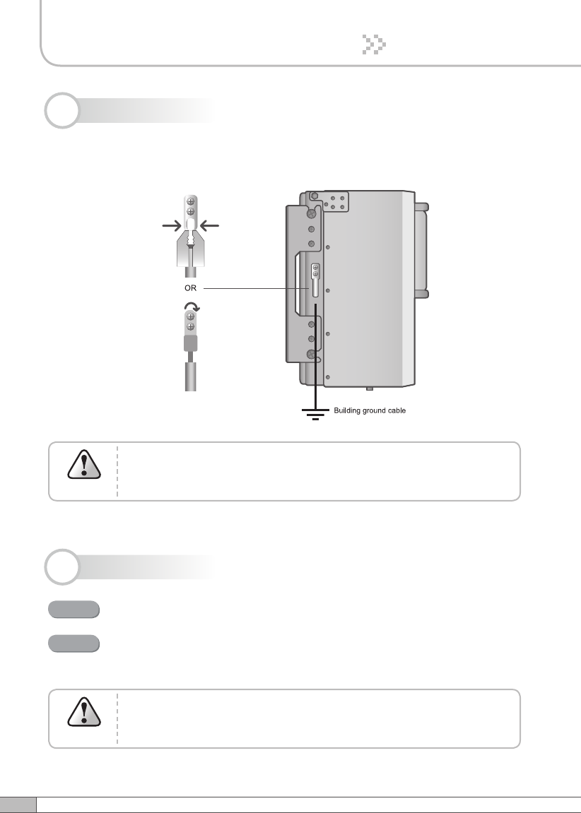
A rod on the left side is intended for a building ground.
Connect the ground cable to the rod.
Dangerously high voltages may occur and damage the equipment if
the equipment is not grounded properly.
Warning
3.3 Grounding
3.4 RF Cable Connection
Connect a cable from a donor antenna to the DONOR ANTENNA Port.
Connect a cable from a repeater’s service antenna to the SERVER
ANTENNA Port.
Step 1
DO NOT connect or disconnect the coaxial cable while the
power is on.
Warning
Step 2
19
User’s Manual
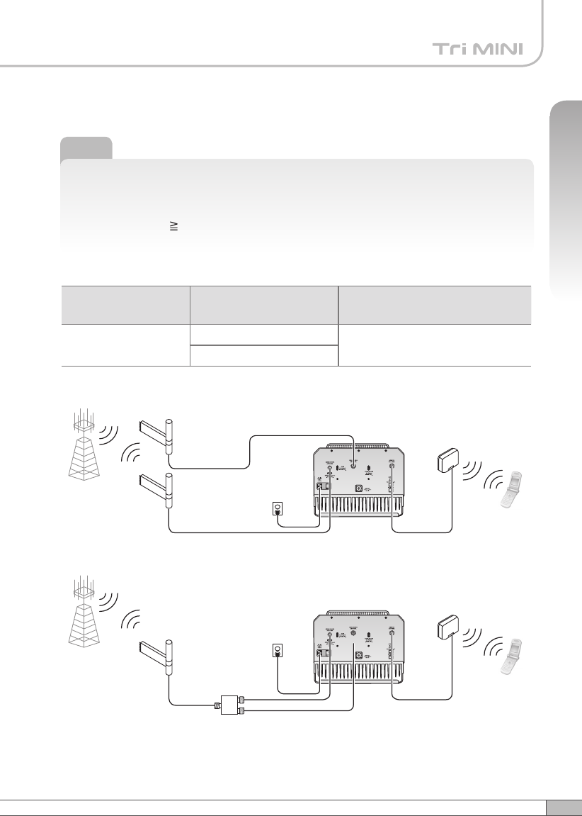
3. Hardware Installation
Note
Enough isolation?
Antenna isolation = Path loss between the server antenna port and the donor
antenna port
Antenna isolation Repeater max. gain +15dB
If antenna isolation < Repeater max. gain +15dB → System oscillation or Low gain
Tri MINI
Plugged in an
AC outlet
Base
Station
Mobile
Station
Donor antenna
for iDEN
Donor antenna
for CDMA
Service
Antenna
Tri MINI
Plugged in an
AC outlet
Base
Station
Mobile
Station
Donor antenna
for iDEN and CDMA
Service
Antenna
2Way
Divider
Model Max Gain Minimum required isolation
(@Max Gain)
RSN-TRI-25/24-DC 40dB to 80dB(CDMA) ≥95dB(80dB+15dB)
50dB to 80dB(iDEN)
20
3. Hardware Installation
3.5 Power On
Connect the power cord.
Plug the power cord into a wall outlet.
Power Switch turns on.
Check if the green LED at the bottom turns on.
Step 1
Step 2
Step 3
Step 4
21
User’s Manual
3. Hardware Installation
Power on the switch to “I”
The switch is located on the
bottom of the main body.
Connect UTP Cross LAN Cable to
a PC and the Tri MINI.
4.1 Connections
The remote port allows remote users to access the repeater through an external
monitoring device.
Local port provides on-site access to the repeater.
4. Operation
22
4. Operation
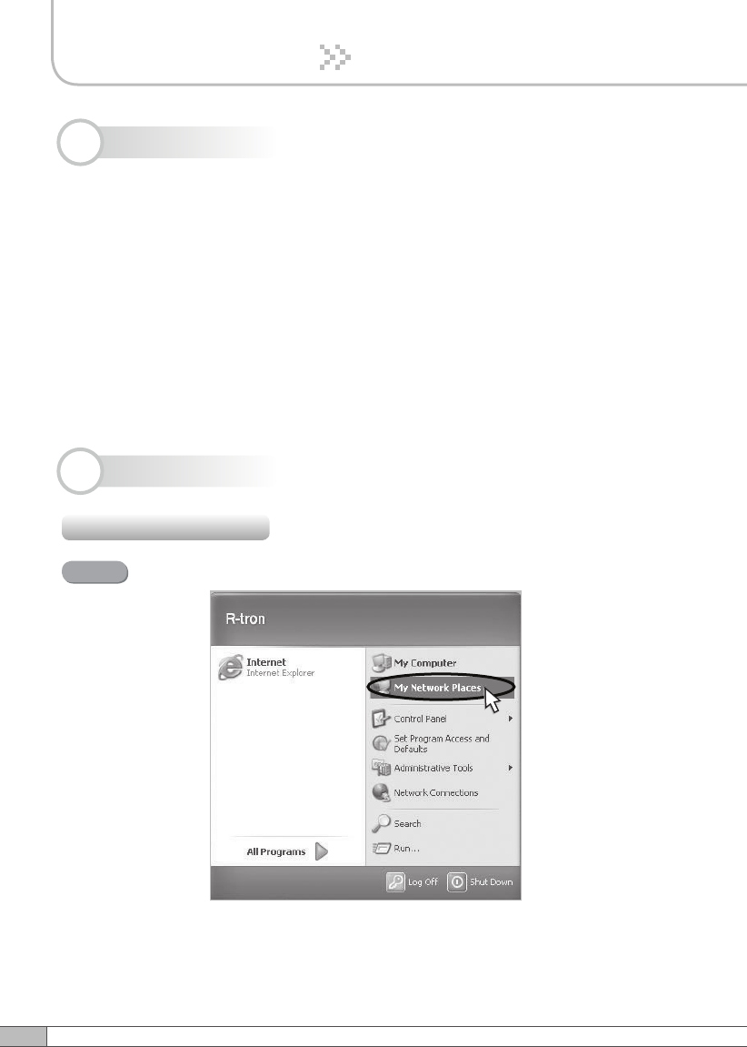
4.3.1 Windows XP
4.3 Network Setup
Tri MINI operates on a customer provided PC based platform with the following
system requirements :
• Windows® 2000, Windows® XP or Windows® Vista
• Internet Explorer 6.0(Recommended) or higher
• 128 MB RAM or higher
• Pentium Ⅲ processor or higher
• RJ-45 jack required
4.2 System Requirements
Click the Start button and My Network Places.
Step 1
23
User’s Manual
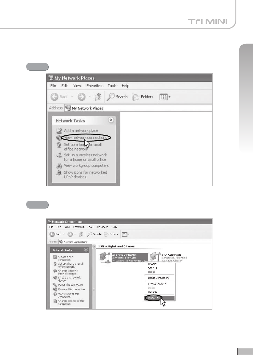
4. Operation
Click View network connections.
Step 2
Right-click Local Area Connection to see a shortcut menu
and click Properties.
Step 3