R tron SNTRIDC Wireless Booster(CDMA) User Manual RSN TRI 25 24 DC 0314 indd
R-tron Inc. Wireless Booster(CDMA) RSN TRI 25 24 DC 0314 indd
R tron >
Contents
- 1. User Manual 1
- 2. User Manual 2
- 3. User Manual 3
User Manual 3
48
4. Operation
49
User’s Manual
4. Operation
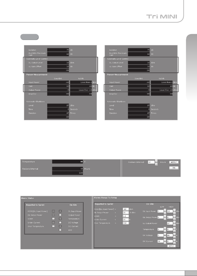
Alarms
•
Reported to Sprint : If an alarm occurs, the repeater will report directly to Sprint
as a SNMP Trap so the LED of ALARM on the repeater does not blink.
•
On Site Alarm : If an alarm occurs, the alarm LED on the repeater will turn on.
Please refer to the troubleshooting section of this manual.
• No change of the values in the alarm range is recommended.
< Alarm Status > < Alarm Range >
50
4. Operation
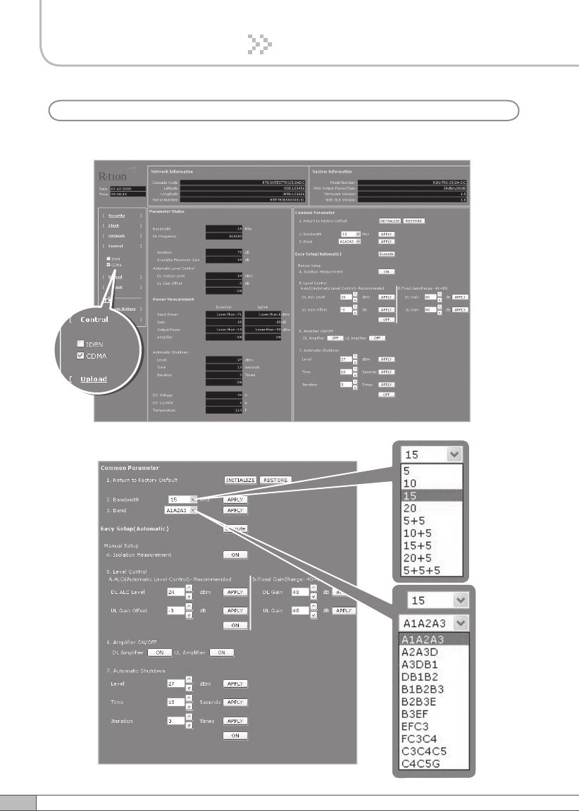
Check CDMA in the left menu.
Setup
b. CDMA
51
User’s Manual
4. Operation
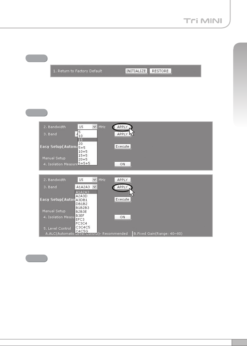
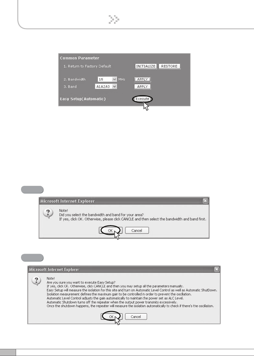
Solution 1. Easy Setup [Recommended]
Return To Factory Defaults
Step 1
Select Bandwidth and Band and click APPLY.
Step 2
• To reset to factory defaults, click INITIALIZE.
• To restore the previous settings, click RESTORE.
Easy Setup
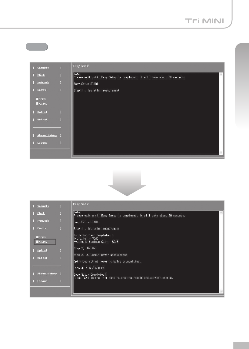
Step 3
Easy Setup proceeds to:
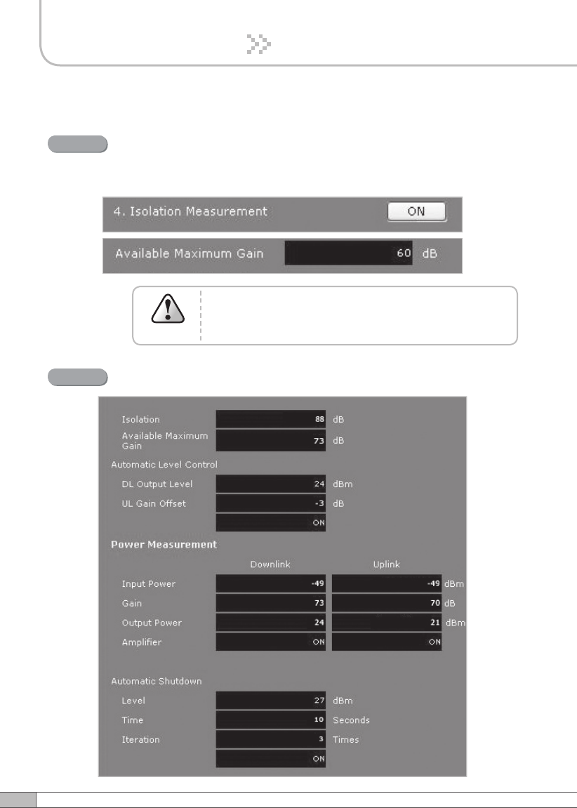
• Isolation measurement On
• Calculation of Available Maximum Gain by the isolation.
• ASD On
•
ALC On to get Maximum DL Output Power 24dBm [Default] or
Maximum Gain 80dB.
53
User’s Manual
52
4. Operation
4. Operation
Click Execute.
Easy setup feature will measure the isolation and limit the maximum gain
accordingly. This will also enable Auto Level Control as well as Auto Shut
Down. These two features are strongly recommended to prevent the
uncontrolled power output, which could have an adverse impact on the
RF network and the repeater. For example, ALC will apply attenuation
automatically when the input signal strength is increased due to the new
base station deployment near the repeater site.
Click OK.
Step 4
Click OK again.
Step 5
53
User’s Manual
52
4. Operation
4. Operation
Setup will automatically begin. This process will take approximately 20
seconds.
Step 6
10~20 seconds
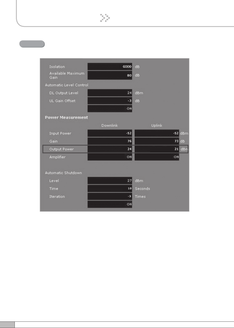
Click CDMA in the left menu.
55
User’s Manual
54
4. Operation
4. Operation
Constant Maximum DL Output Power 24dBm
if the DL Input Power >= -56dBm
Result 1

55
User’s Manual
54
4. Operation
4. Operation
Maximum Gain 80dB if the DL Input Power < -56dBm.
Result 2
57
User’s Manual
56
4. Operation
4. Operation
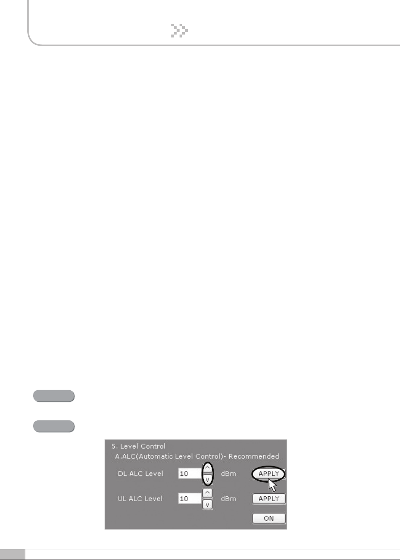
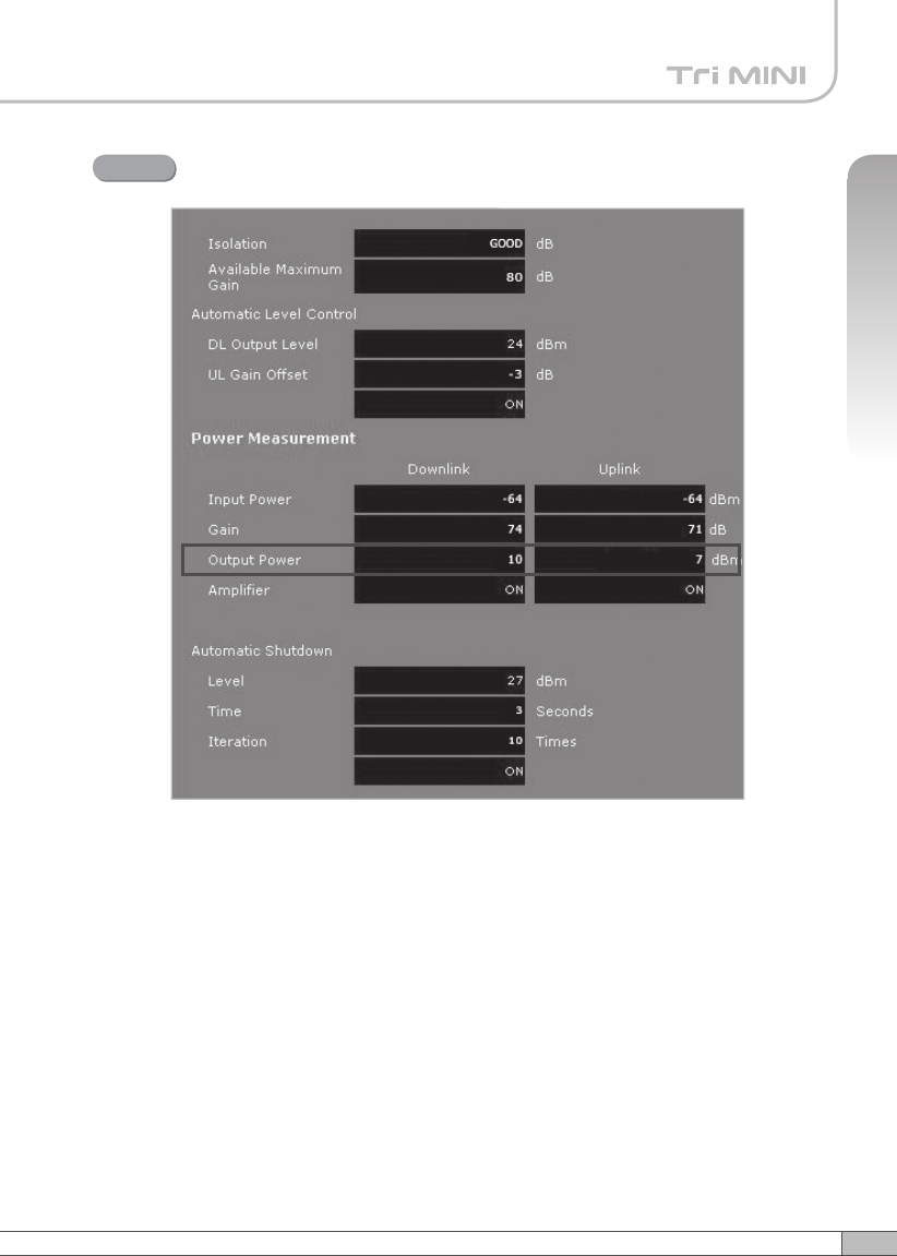
Solution 2. DL Output Power < Max. 24dBm
Repeat step 1 through step 6.
Step 2A
Step 1A
Change the level at Automatic Level Control and click APPLY.
After running Easy Setup or Isolation Measurement, Isolation value is displayed
with “95” when the isolation is higher than 95dB, or it is displayed with the actual
value when the isolation is lower than 95dB.
• Automatic Level Control: Type under 24 and then click APPLY and ON.
[Example]
For the repeater with 24dBm maximum output power, 80dB maximum gain/
40dB gain control range, → If the signal -36dBm and the ALC is set as 24dBm,
the gain will be 60dB to adjust to the output power.
If the input signal is -61dBm, the output power will be 19dBm by the limitation of
the maximum gain even though the ALC is set as 24dBm.
•
Automatic Shutdown: Type the desired values for dBm, seconds, and times
and then click APPLY and ON. (e.g. 27 dBm, 10 seconds, 3 times)
[Example]
For the repeater with 24dBm maximum output power, 80dB maximum
gain/40dB gain control range, Assuming ASD Level: 27dBm, ASD Time:
10seconds, ASD Count: 3.
If the output power is 27dBm (ASD LEVEL) and higher, the repeater will
shutdown for 10 seconds (ASD TIME). If shutdown occurs 3 times (ASD
COUNT), the 4th shutdown will be permanent.
57
User’s Manual
56
4. Operation
4. Operation
Constant output power set as the ALC level.
Result
59
User’s Manual
58
4. Operation
4. Operation
Solution 3. Fixed Gain [Not Recommended]
Easy Setup will calculate the Available Maximum Gain which
defines the maximum gain to be setup.
Repeat step 1 through step 6.
Step 1B
DO NOT setup the gain higher than the Available
Maximum Gain.
Warning
Read DL Input Power and the gain controlled by Easy Setup.
Step 2B
59
User’s Manual
58
4. Operation
4. Operation
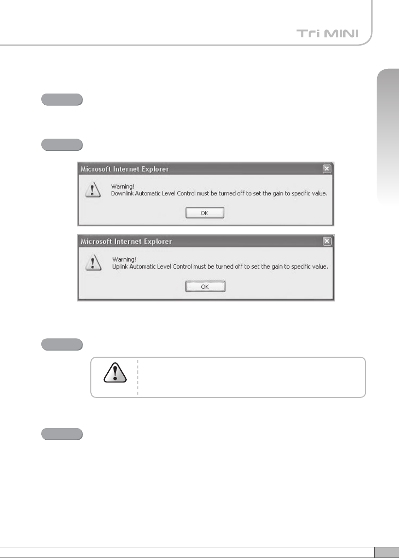
Turn off DL Amplifier and UL Amplifier.
Step 3B
ALC must be turned off; otherwise, the following message appears.
Step 4B
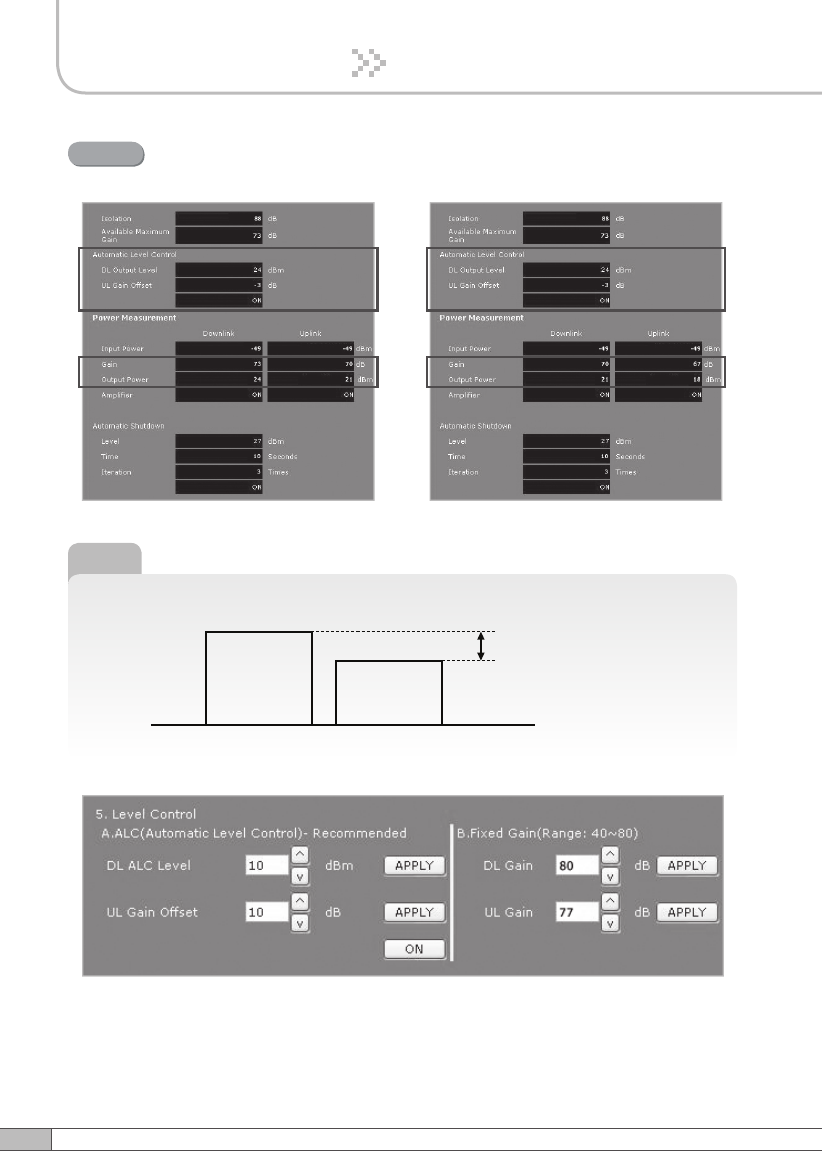
Change DL Gain and UL Gain.
The gain must be lower than the current value and
Available Maximum Gain.
Warning
Step 5B
Turn on DL Amplifier and UL Amplifier.
Step 6B
61
User’s Manual
60
4. Operation
4. Operation
DL and UL gain are fixed and the output power depends on the input
power.
Result
►
Tip
Applying Uplink Gain Offset
Downlink Gain Uplink Gain
Uplink Gain Offset
61
User’s Manual
60
4. Operation
4. Operation
Uplink Gain Offset = -3dB
Result
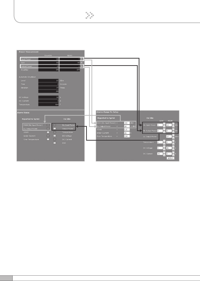
Alarms
< Alarm Status > < Alarm Range >
※ Restore
Restore recovers the service by turning on the amplifiers of repeater
fundamentally.
After a permanent shutdown, the Restore turns on the amplifiers of the repeater
with the period of Restore Interval.
62
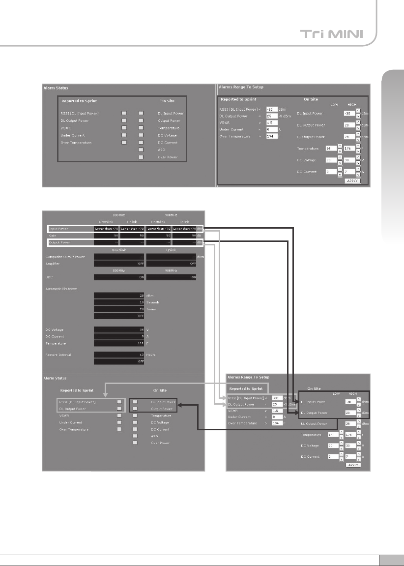
• Reported to Sprint : If an alarm occurs, the repeater will report directly to Sprint
as a SNMP Trap so the LED of ALARM on the repeater does not blink.
•
On Site Alarm : If an alarm occurs, the alarm LED on the repeater will turn on.
Please refer to the troubleshooting section of this manual.
• No change of the values in the alarm range is recommended.
4. Operation
63
User’s Manual
4. Operation
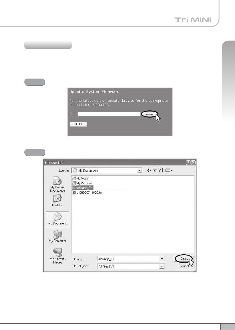
A pop-up window will appear. Select the firmware file and click Open.
Step 2
Click Upload in the left menu.
4.5.5.1 Update: System Firmware
4.5.5 Upload
Click Browse.
Step 1
64
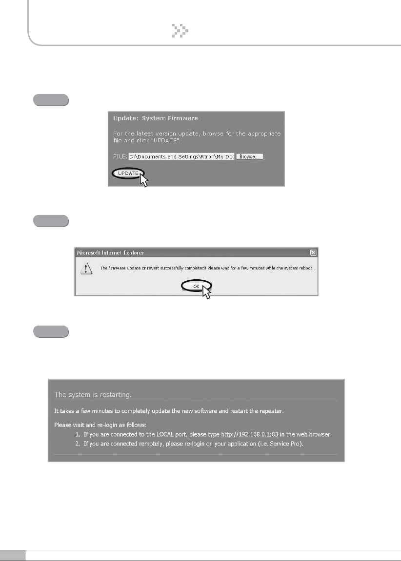
4. Operation
Click UPDATE.
Step 3
A pop-up window will appear after completing all the update processes.
Click OK to reboot the system.
Step 4
It will take a few minutes to update the new firmware.
If the system reboots, go to the login page and login again.
* Login page: http://192.168.0.1:83 (Local access)
A specified IP address on DHCP(Remote access).
Step 5
65
User’s Manual
4. Operation
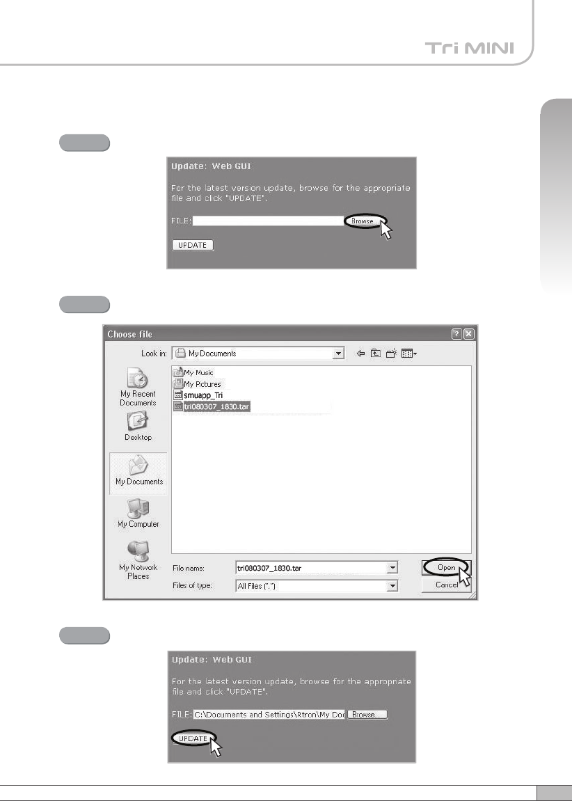
4.5.5.2 Update: Web GUI
Click Browse.
Step 1
A pop-up window will appear. Select the GUI file and click Open.
Step 2
Click UPDATE.
Step 3
66
4. Operation
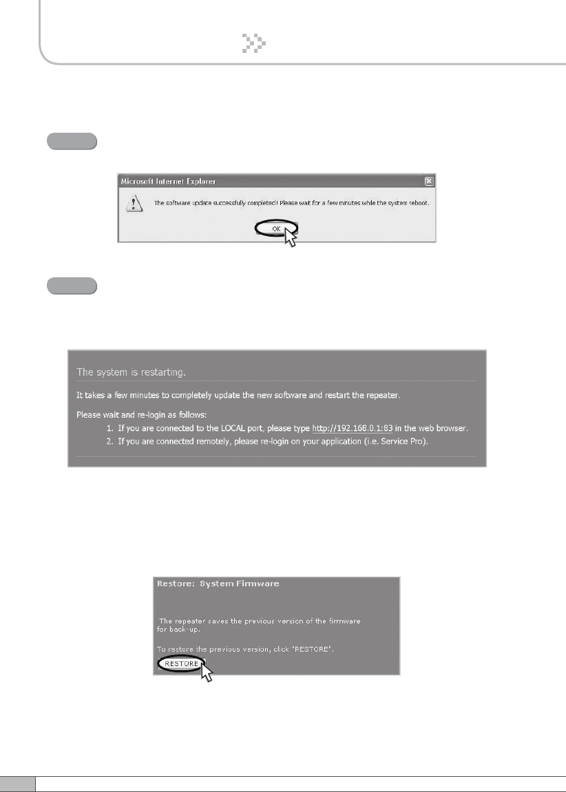
A pop-up window will appear after completing all the update processes.
Click OK to reboot the system.
Step 4
4.5.5.3 Restore
To restore the previous version, click RESTORE.
It will take a few minutes to update the new Web GUI.
If the system reboots, go to the login page and login again.
* Login page: http://192.168.0.1:83 (Local access)
A specified IP address on DHCP(Remote access).
Step 5
67
User’s Manual
4. Operation
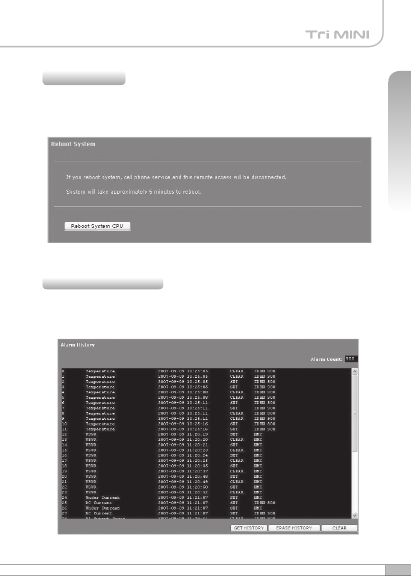
Click Reboot in the left menu.
In this menu, you can reboot the system.
4.5.6 Reboot
Click Alarm History in the left menu.
Click GET HISTORY, the history list of alarm issued will be displayed.
4.5.7 Alarm History
68
4. Operation
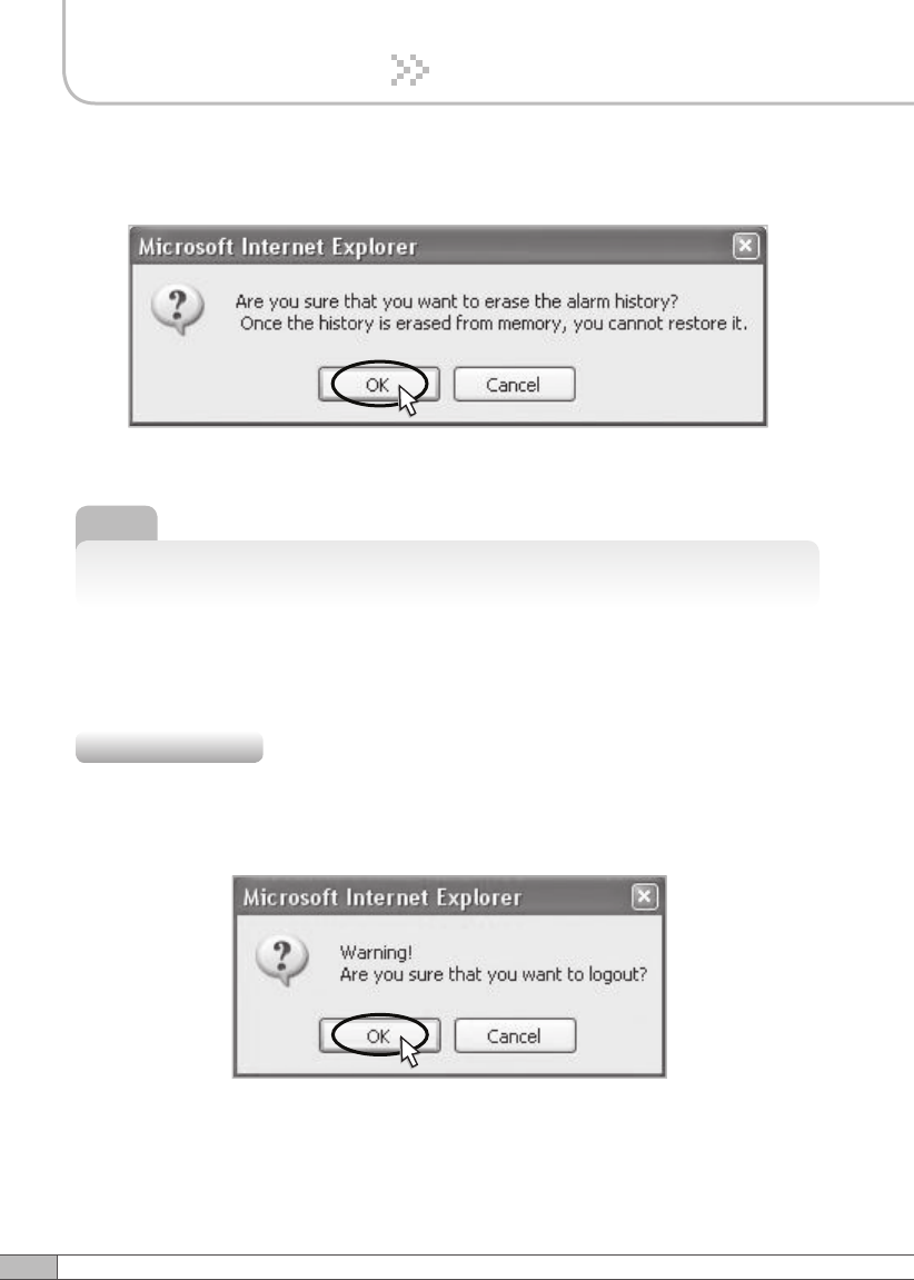
To erase the alarm history on the memory, click ERASE HISTORY.
A confirmation pop-up window will appear and click OK.
Note
Up to 300 alarm lists can be stored in the memory.
If you want to logout, click Logout in the left menu.
A warning pop-up window will appear and then click OK to logout.
4.5.8 Logout
To clear the alarm history on the screen, click CLEAR.
69
User’s Manual
4. Operation
Before contacting your service dealer, please make sure you refer to the following
guide. If the Tri MINI does not work normally after completing the following
troubleshooting, please contact your local dealer or service center.
Problem Cause Solution
No LED On Check the power cord for secure connection.
Cannot
communicate
with the
repeater.
Check if the LAN cable is connected to the repeater
and your computer, or your computer to set IP
address. Or please disable and enable the Local
Area Connection.
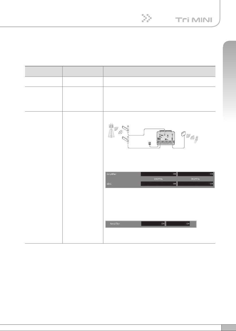
The mobile
phone is not
working well.
Turn on the power.
or
< a. iDEN >
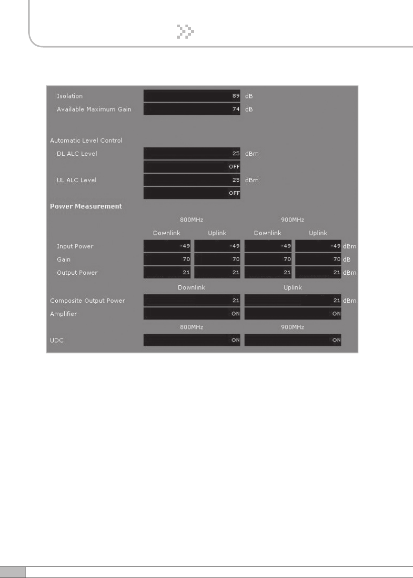
Check if the DL Amplifier, the UL Amplifier,
iDEN 800 UDC and iDEN 900 UDC in Power
Measurement are displayed ON.
< b. CDMA >
Check if the DL Amplifier and the UL Amplifier of
Parameter Status are displayed ON.
5. Troubleshooting
Tri MINI
Plugged in an
AC outlet
Base
Station
Mobile
Station
Donor antenna
for iDEN
Donor antenna
for CDMA
Service
Antenna
Tri MINI
Plugged in an
AC outlet
Base
Station
Mobile
Station
Donor antenna
for iDEN a nd CDMA
Service
Antenna
2Way
Divider
70
5. Troubleshooting
Problem Cause Solution
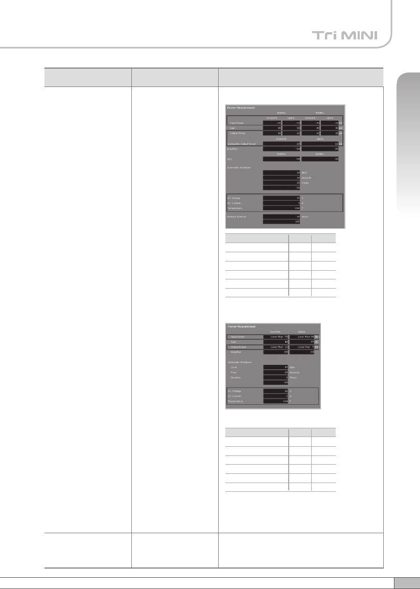
Oscillation < a. iDEN >
1. The values above are changed randomly
under operating of DL ALC, UL ALC, and
ASD.
2. DL Amplifier and UL Amplifier are on and off
iteratively.
< b. CDMA >
1. The values above are changed randomly
under operating of DL ALC, UL ALC, and
ASD.
2. DL Amplifier and UL Amplifier are on and off
iteratively.
Turn off the
repeater.
Measure
the isolation
and verify if
the isolation
between the
donor antenna
and the server
antenna is
enough for the
repeater. And
then redo the
easy set up
or set up the
repeater.
Green LED →
steady
Red LED →
flashing
Donor antenna connection → Good
Server antenna connection → Bad
Check the cable
connection
to the server
antenna and its
VSWR.
Tri MINI
Plugged in an
AC outlet
Base
Station
Mobile
Station
Donor antenna
for iDEN
Donor antenna
for CDMA
Service
Antenna
Tri MINI
Plugged in an
AC outlet
Base
Station
Mobile
Station
Donor antenna
for iDEN a nd CDMA
Service
Antenna
2Way
Divider
71
User’s Manual
5. Troubleshooting
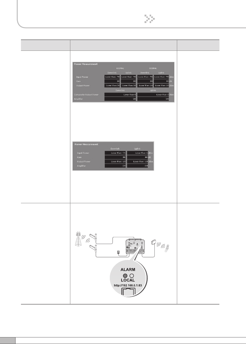
Problem Cause Solution
The red light turns on.
< a. iDEN >
< b. CDMA >
Check if the value above is out of range.
If the Input Power or Output Power is out of
range, please contact Technical Support.
Download site: www.r-tron.com
Toll Free: 888-31R-TRON
Red & green LEDs are
flashing irregularly.
Malfunction of PSU. Please contact Technical Support.
Download site: www.r-tron.com
Toll Free: 888-31R-TRON
Lower
-
-
-
14°F
20V
0A
DL Input Power
DL Output Power
UL Output Power
Temperature
DC Voltage
DC Current
Upper
-30dBm
28dBm
28dBm
176°F
30V
7A
On Site Alarms Range
Lower
-90dBm
-10dBm
-
-14°F
20AV
0A
DL Input Power
DL Output Power
UL Output Power
Temperature
DC Voltage
DC Current
Upper
-20dBm
27dBm
27dBm
176°F
30V
7A
On Site Alarms Range
72
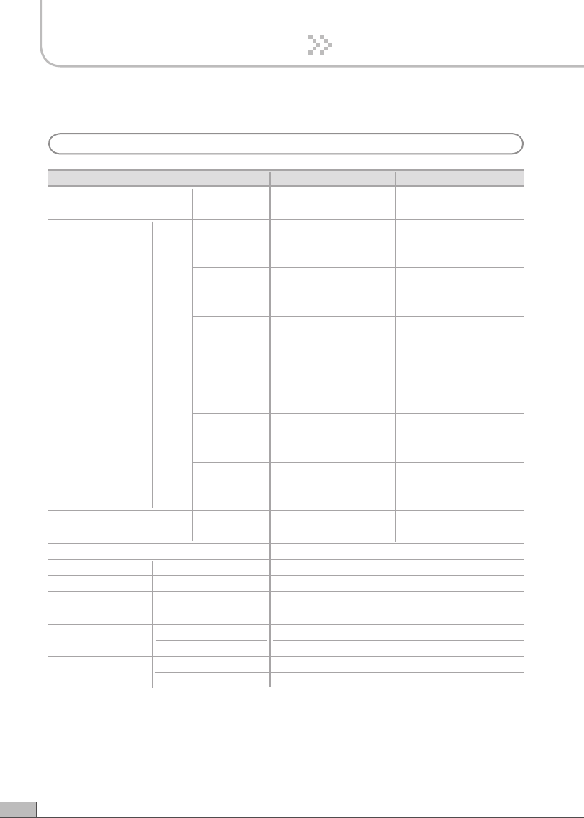
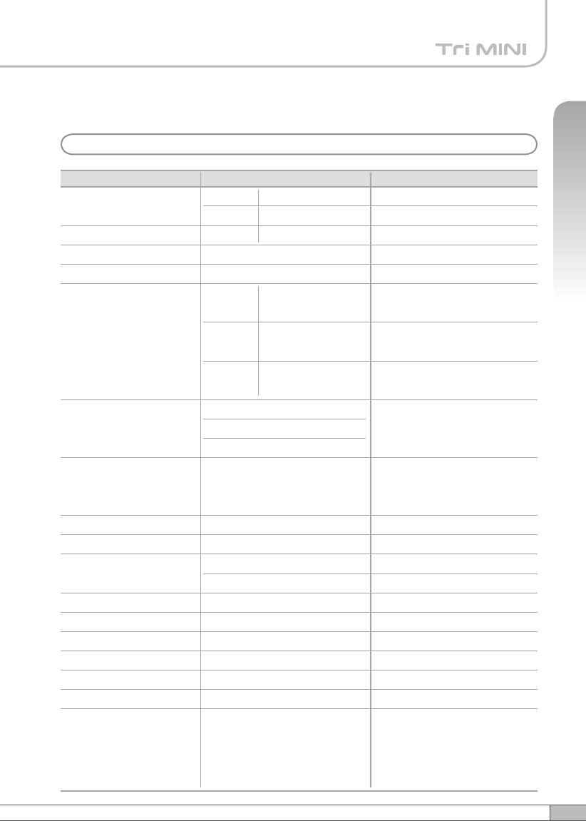
RF Characteristics
6. Specifications
a. iDEN
Parameter iDEN 800
DL & UL
Selectable Bandwidth
DL
UL
iDEN 900
In-band BW:18MHz
In-band BW:7.0MHz In-band BW:5MHz
18MHz-
bandwidth
Frequency
Selection
Roll off
Ripple
851~869MHz
851~868.8MHz
851~868.6MHz
7MHz-
bandwidth
862~869MHz
862~868.8MHz
862~868.6MHz
5MHz-
bandwidth
935~940MHz
935~939.8MHz
935~939.6MHz
18MHz-
bandwidth
806~824MHz
806~823.8MHz
806~823.6MHz
7MHz-
bandwidth
817~824MHz
817~823.8MHz
817~823.6MHz
5MHz-
bandwidth
896~901MHz
896~900.8MHz
896~900.6MHz
≤65dBc
@Fedge+ / -500KHz
5dB Max.
12dB Max.
2.5dB (Typical)
Gain 50dB to 80dB
Output Power 25dBm
Delay 8.0µs Max.
VSWR
DL & UL
Input Range -25dBm Max.
DL
DL & UL
DL & UL
DL & UL 1.5Max.
DL & UL ≤65dBc
@Fedge+ / -500KHz
UL Noise
Figure
80dB Gain
50dB Gain
-35dBm Max.
UL
73
User’s Manual
6. Specifications
b. CDMA
Parameter Specification
Frequency
Remarks
DL
UL
DL/UL
1930~1995MHz
1850~1915MHz
-56dBm
Normal Input
Output Power Level
Gain
Attenuator
Spurious
Roll Off
Gain Flatness
Group Delay
Noise Figure
VSWR
Isolation DET Level
Isolation DET Range
Consumption power
Operating Temp
Storage temperature
Band Selection
DL
UL
VVA
Range: 0~40dB
Accuracy: ±0.7dB
Range: 0~40dB
Accuracy: ±0.7dB
±3dB
24dBm
40dB ~ 80dB ± 2dB
Temperature
Compensation
Min 29dB @±885KHz
Min 39dB @±1.98MHz
Min -13dBm@±2.25MHz
Discontinuous 3FA /
Continuous 7FA
Min 50dBc @±1MHz
5 / 10 / 15 / 20MHz-bandwidth,
5+5 / 10+5 / 15+5 / 20+5MHz,
5+5+5MHz.
3.0dB (P-P)
Max 5us
Max 4.5dB
Max 12dB
Max 1.5:1
26dBm ± 1dB
-75dBm ~ -50dBm,
≤100W
-10°C~ 50°C
-20°C~ 60°C
BW : 65MHz
ATT: 0dB
ATT: 40dB
BW : 65MHz
BW : UL_65MHz
REF: -50dBm / 4.7V
5MHz, 10MHz, 15MHz,
20MHz
5+5MHz, 10+5MHz,
15+5MHz, 20+5MHz,
5+5+5MHz
74
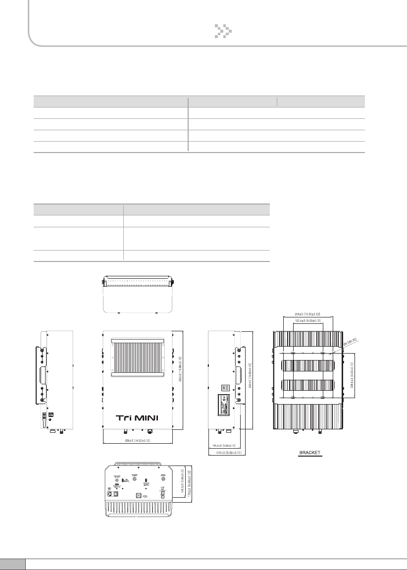
6. Specifications
Electrical & Environmental Specification
Parameter iDEN 800 iDEN 900
Power supply 110V~125V AC, 60Hz typical
Operating temperature *-10˚C~50˚C (14˚F~122˚F)
Storage temperature -20˚C~60˚C (-4˚F~140˚F)
Consumption power ≤192.5W, (additional 24W)
Mechanical Specifications
Parameter Specification
N-female x 3, SMA-female x 3
14.48 X16.73 X 11.37(Inch),
368 X 425 X 289(mm)
31.7kg (69.88lbs)
RF connectors
Size
Weight
The specifications are subject to change without any prior notification.
75
User’s Manual
6. Specifications
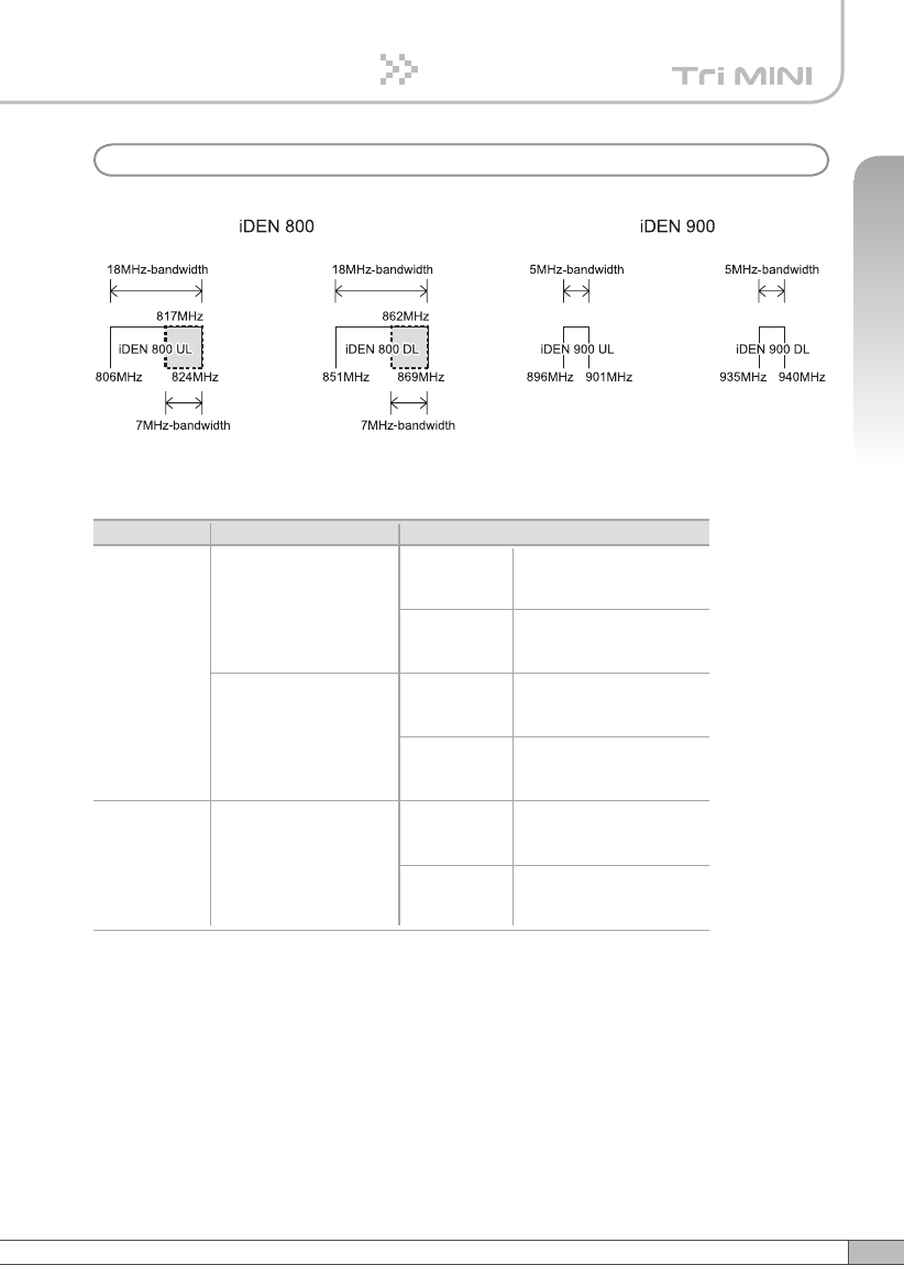
7. Appendix
a. iDEN
The Operating Bandwidth and Frequencies of iDEN
Mode Bandwidth
18MHz-bandwidth
iDEN 800
iDEN 900
Operating Frequency
Downlink
851 ~ 869MHz
851 ~ 868.8MHz
851 ~ 868.6MHz
Uplink
806 ~ 824MHz
806 ~ 823.8MHz
806 ~ 823.6MHz
7MHz-bandwidth
Downlink
862 ~ 869MHz
862 ~ 868.8MHz
862 ~ 868.6MHz
Uplink
817 ~ 824MHz
817 ~ 823.8MHz
817 ~ 823.6MHz
5MHz-bandwidth
Downlink
935 ~ 940MHz
935 ~ 939.8MHz
935 ~ 939.6MHz
Uplink
896 ~ 901MHz
896 ~ 900.8MHz
896 ~ 900.6MHz
76
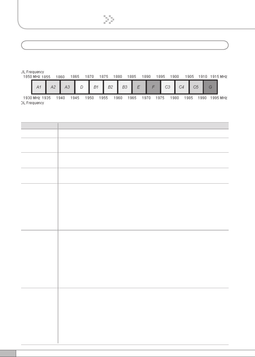
7. Appendix
• Bandwidth/Frequency:
The values of the bandwidth and frequency of CDMA
15+5 A1A2A3+B1, A1A2A3+B2, A1A2A3+B3, A1A2A3+E, A1A2A3+F,
A1A2A3+C3, A1A2A3+C4, A1A2A3+C5, A1A2A3+G, A2A3D+B2,
A2A3D+B3, A2A3D+E, A2A3D+F, A2A3D+C3, A2A3D+C4, A2A3D+C5,
A2A3D+G, A3DB1+B3, A3DB1+E, A3DB1+F, A3DB1+C3, A3DB1+C4,
A3DB1+C5, A3DB1+G, DB1B2+E, DB1B2+F, DB1B2+C3, DB1B2+C4,
DB1B2+C5, DB1B2+G, B1B2B3+F, B1B2B3+C3, B1B2B3+C4,
B1B2B3+C5, B1B2B3+G, B2B3E+C3, B2B3E+C4, B2B3E+C5,
B2B3E+G, B3EF+C4, B3EF+C5, B3EF+G, EFC3+C5, EFC3+G,
FC3C4+G
10+5 A1A2+D, A1A2+B1, A1A2+B2, A1A2+B3, A1A2+E, A1A2+F,
A1A2+C3, A1A2+C4, A1A2+C5, A2A3+G, A2A3+B1, A2A3+B2,
A2A3+B3, A2A3+E, A2A3+F, A2A3+C3, A2A3+C4, A2A3+C5,
A2A3+G, A3D+B2, A3D+B3, A3D+E, A3D+F, A3D+C3, A3D+C4,
A3D+C5, A3D+G, DB1+B3, DB1+E, DB1+F, DB1+C3, DB1+C4,
DB1+C5, DB1+G, B1B2+E, B1B2+F, B1B2+C3, B1B2+C4, B1B2+C5,
B1B2+G, B2B3+F, B2B3+C3, B2B3+C4, B2B3+C5, B2B3+G,
B3E+C3, B3E+C4, B3E+C5, B3E+G, EF+C4, EF+C5, EF+G,
FC3+C5, FC3+G, C3C4+G
Bandwidth Operating Frequency
5
10
15 A1A2A3, A2A3D, A3DB1, DB1B2, B1B2B3, B2B3E, B3EF, EFC3,
FC3C4, C3C4C5, C4C5G
20 A1A2A3D, A2A3DB1, A3DB1B2, DB1B2B3, B1B2B3E, B2B3EF,
B3EFC3, EFC3C4, FC3C4C5, C3C4C5G
5+5 A1+A3, A1+D, A1+B1, A1+B2, A1+B3, A1+E, A1+F, A1+C3, A1+C4,
A1+C5, A1+G, A2+D, A2+B1, A2+B2, A2+B3, A2+E, A2+F, A2+C3,
A2+C4, A2+C5, A2+G, A3+B1, A3+B2, A3+B3, A3+E, A3+F, A3+C3,
A3+C4, A3+C5, A3+G, D+B2, D+B3, D+E, D+F, D+C3, D+C4, D+C5,
D+G, B1+B3, B1+E, 1+F, B1+C3, B1+C4, B1+C5, B1+G, B2+E, B2+F,
B2+C3, B2+C4, B2+C5, B2+G, B3+F, B3+C3, B3+C4, B3+C5, B3+G,
E+C3, E+C4, E+C5, E+G, F+C4, F+C5, F+G, C3+C5, C3+G
A1A2, A2A3, A3D, DB1, B1B2, B2B3, B3E, EF, FC3, C3C4, C4C5,
C5G
A1, A2, A3, D, B1, B2, B3, E, F, C3, C4, C5, G
b. CDMA

77
User’s Manual
7. Appendix
Bandwidth Operating Frequency
20+5 A1A2A3D+B2, A1A2A3D+B3, A1A2A3D+E, A1A2A3D+F,
A1A2A3D+C3, A1A2A3D+C4, A1A2A3D+C5, A1A2A3D+G,
A2A3DB1+B3, A2A3DB1+E, A2A3DB1+F, A2A3DB1+C3,
A2A3DB1+C4, A2A3DB1+C5, A2A3DB1+G, A3DB1B2+E,
A3DB1B2+F, A3DB1B2+C3, A3DB1B2+C4, A3DB1B2+C5,
A3DB1B2+G, DB1B2B3+F, DB1B2B3+C3, DB1B2B3+C4,
DB1B2B3+C5, DB1B2B3+G, B1B2B3E+C3, B1B2B3E+C4,
B1B2B3E+C5, B1B2B3E+G, B2B3EF+C4, B2B3EF+C5, B2B3EF+G,
B3EFC3+C5, B3EFC3+G, EFC4+G
5+5+5 A1+A3+B1, A1+A3+B2, A1+A3+B3, A1+A3+E, A1+A3+F, A1+A3+C3,
A1+A3+C4, A1+A3+C5, A1+A3+G, A1+D+B2, A1+D+B3, A1+D+E,
A1+D+F, A1+D+C3, A1+D+C4, A1+D+C5, A1+D+G, A1+B1+B3,
A1+B1+E, A1+B1+F, A1+B1+C3, A1+B1+C4, A1+B1+C5, A1+B1+G,
A1+B2+E, A1+B2+F, A1+B2+C3, A1+B2+C4, A1+B2+C5, A1+B2+G,
A1+B3+F, A1+B3+C3, A1+B3+C4, A1+B3+C5, A1+B3+G, A1+E+C3,
A1+E+C4, A1+E+C5, A1+E+G, A1+F+C4, A1+F+C5, A1+F+G,
A1+C3+C5, A1+C3+G, A1+C4+G, A2+D+B2, A2+D+B3, A2+D+E,
A2+D+F, A2+D+C3, A2+D+C4, A2+D+C5, A2+D+G, A2+B1+B3,
A2+B1+E, A2+B1+F, A2+B1+C3, A2+B1+C4, A2+B1+C5, A2+B1+G,
A2+B2+E, A2+B2+F, A2+B2+C3, A2+B2+C4, A2+B2+C5, A2+B2+G,
A2+B3+F, A2+B3+C3, A2+B3+C4, A2+B3+C5, A2+B3+G, A2+E+C3,
A2+E+C4, A2+E+C5, A2+E+G, A2+F+C4, A2+F+C5, A2+F+G,
A2+C3+C5, A2+C3+G, A2+C4+G, A3+B1+B3, A3+B1+E, A3+B1+F,
A3+B1+C3, A3+B1+C4, A3+B1+C5, A3+B1+G, A3+B2+E, A3+B2+F,
A3+B2+C3, A3+B2+C4, A3+B2+C5, A3+B2+G, A3+B3+F, A3+B3+C3,
A3+B3+C4, A3+B3+C5, A3+B3+G, A3+E+C3, A3+E+C4, A3+E+C5,
A3+E+G, A3+F+C4, A3+F+C5, A3+F+G, A3+C3+C5, A3+C3+G,
A3+C4+G, D+B2+E, D+B2+F, D+B2+C3, D+B2+C4, D+B2+C5,
D+B2+G, D+B3+F, D+B3+C3, D+B3+C4, D+B3+C5, D+B3+G,
D+E+C3, D+E+C4, D+E+C5, D+E+G, D+F+C4, D+F+C5, D+F+G,
D+C3+C5, D+C3+G, D+C4+G, B1+B3+F, B1+B3+C3, B1+B3+C4,
B1+B3+C5, B1+B3+G, B1+E+C3, B1+E+C4, B1+E+C5, B1+E+G,
B1+F+C4, B1+F+C5, B1+F+G, B1+C3+C5, B1+C3+G, B1+C4+G,
B2+E+C3, B2+E+C4, B2+E+C5, B2+E+G, B2+F+C4, B2+F+C5,
B2+F+G, B2+C3+C5, B2+C3+G, B2+C4+G, B3+F+C4, B3+F+C5,
B3+F+G, B3+C3+C5, B3+C3+G, B3+C4+G, E+C3+C5, E+C3+G,
E+C4+G, F+C4+G

78
LIMITED WARRANTY
This product, as supplied and distributed by R-tron, in the original carton, is
warranted by R-tron against manufacturing defects in materials and workmanship
for a limited warranty period of:
Five (5) Year Parts and Labor
This limited warranty begins on the original date of purchase, and is valid only on
products purchased and used in the United States. R-tron will repair or replace
this product, at our option and at no charge as stipulated herein, with new or
reconditioned parts or products if found to be defective during the limited warranty
period specified above. All replaced parts and products become the property of R-
tron and must be returned to R-tron. Replacement parts and products assume the
remaining original warranty.
This limited warranty covers manufacturing defects in materials and workmanship
encountered in normal, and except to the extent otherwise expressly provided
for in this statement, use of this product, and shall not apply to the following,
including, but not limited to: damage which occurs in installation; applications and
uses for which this product was not intended; altered product or serial numbers;
cosmetic damage or exterior finish; accidents, abuse, neglect, fire, water, lightning
or other acts of nature; use of products, equipment, systems, utilities, services,
parts, supplies, accessories, applications, installations, repairs, external wiring
or connectors not supplied or authorized by R-tron which damage this product
or result in service problems; or incorrect electrical line voltage, fluctuations and
surges; customer adjustments and failure to follow operating instruction. R-tron
does not warrant uninterrupted or error-free operation of the product.
THERE ARE NO EXPRESS WARRANTIES OTHER THAN THOSE
LISTED AND DESCRIBED ABOVE, AND NO WARRANTIES
WHETHER EXPRESS OR IMPLIED, INCLUDING, BUT NOT LIMITED
TO, ANY IMPLIED WARRANTIES OF MERCHANTABILITY OR
FITNESS FOR A PARTICULAR PURPOSE, SHALL APPLY AFTER
THE EXPRESS WARRANTY PERIODS STATED ABOVE, AND NO
OTHER EXPRESS WARRANTY OR GUARANTY GIVEN BY ANY
PERSON, FIRM OR CORPORATION WITH RESPECT TO THIS
PRODUCT SHALL BE BINDING ON R-tron.
Warranty
79
User’s Manual
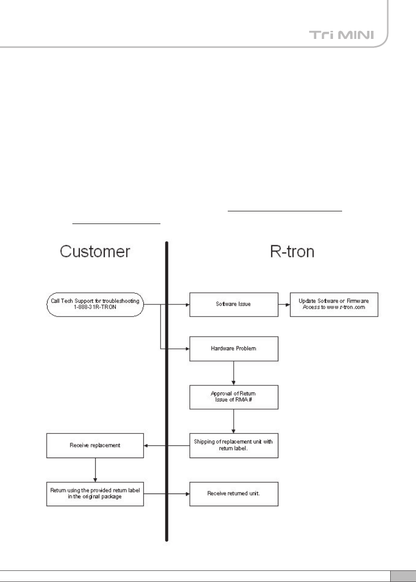
Return Material Authorization(RMA) Procedure
The return and exchange of products are not allowed without prior approval from
R-tron America, Inc.
Please follow the exchange procedure below.
1. Call Tech Support for troubleshooting.
2. If the device has a hardware problem, R-tron will replace it if it is within
warranty.
A RMA number will be issued for the return.
3. R-tron will ship the replacement and a return label will be provided.
4. The customer must return the product using the original packaging,
including accessories.
80
MENO