RELM Communications RPV516A VHF FM Transceiver User Manual RPV516A SAR Test Report revised 121901
RELM Communications Inc VHF FM Transceiver RPV516A SAR Test Report revised 121901
Contents
- 1. Users Manual
- 2. Revised Manual 121901
- 3. Revised Manual 010402
Revised Manual 121901
CELLTECH RESEARCH INC. Test Report S/N: 092601-169ARU
1955 Moss Court, Kelowna Date of Tests: October 16, 2001
B.C. Canada V1Y 9L3 FCC SAR Evaluation
_________________________________________________________________________________________________________
© 2001 Celltech Research Inc.
CERTIFICATE OF COMPLIANCE
SAR EVALUATION
This wireless portable device has been shown to be compliant for localized Specific Absorption Rate (SAR)
for controlled environment/occupational exposure limits specified in ANSI/IEEE Std. C95.1-1992 and had
been tested in accordance with the measurement procedures specified in ANSI/IEEE Std. C95.3-1999.
I attest to the accuracy of data. All measurements were performed by me or were made under my
supervision and are correct to the best of my knowledge and belief. I assume full responsibility for the
completeness of these measurements and vouch for the qualifications of all persons taking them.
Celltech Research Inc. certifies that no party to this application has been denied FCC benefits pursuant to Section 5301 of the Anti-Drug
Abuse Act of 1988, 21 U.S.C. 853(a).
Shawn McMillen
General Manager
Celltech Research Inc.
Test Lab:
CELLTECH RESEARCH INC.
Testing and Engineering Lab
1955 Moss Court
Kelowna, B.C.
Canada V1Y 9L3
Phone: 250 - 860-3130
Fax: 250 - 860-3110
Toll Free: 1-877-545-6287
e-mail: info@celltechlabs.com
web site: www.celltechlabs.com
Applicant Information:
RELM WIRELESS CORPORATION
7100 Technology Drive
West Melbourne, FL 32904
FCC Rule Part(s): 2.1093; ET Docket 96-326
FCC ID: ARURPV516A
Model(s): RPV516A
EUT Type: Portable VHF PTT Radio Transceiver
Modulation: FM
Tx Frequency Range: 150.05 - 173.95 MHz
Conducted Power Tested: 5.3 Watts
Antenna Type: Helical Whip
Battery Type: 7.2VDC, 1100mAh, Ni-Cd
Body-Worn Accessory: 1.4cm Belt-Clip

CELLTECH RESEARCH INC. Test Report S/N: 092601-169ARU
1955 Moss Court, Kelowna Date of Tests: October 16, 2001
B.C. Canada V1Y 9L3 FCC SAR Evaluation
_________________________________________________________________________________________________________
© 2001 Celltech Research Inc.
TABLE OF CONTENTS
1.0 INTRODUCTION………………………………………………………… 1
2.0 DESCRIPTION OF EQUIPMENT UNDER TEST……………………. 1
3.0 SAR MEASUREMENT SYSTEM ……………………………………… 2
4.0 SAR MEASUREMENT SUMMARY…………………………………… 3-4
5.0 DETAILS OF SAR EVALUATION………………………………….…. 5
6.0 EVALUATION PROCEDURES……..………………………………….. 5
7.0 SYSTEM VALIDATION……………………………………………….... 6
8.0 TISSUE PARAMETERS………………………………………………… 6
9.0 SIMULATED TISSUES…………………………….……………………. 7
10.0 SAR SAFETY LIMITS…….…..………………………………………… 7
11.0 ROBOT SYSTEM SPECIFICATIONS.………………………………… 8
12.0 PROBE SPECIFICATION……………………………………………… 9
13.0 SAM PHANTOM…………………………………….….………………... 9
14.0 DEVICE HOLDER……………………………………..………………… 9
15.0 TEST EQUIPMENT LIST………………………………………..……… 10
16.0 MEASUREMENT UNCERTAINTIES…………………………………. 11
17.0 REFERENCES……………………………………………………………. 12
APPENDIX A - SAR MEASUREMENT DATA…………...……………………. 13
APPENDIX B - DIPOLE VALIDATION………………………………………... 14
APPENDIX C - PROBE CALIBRATION……………………………………….. 15
APPENDIX D – DETERMINATION OF PROBE CONVERSION FACTORS 16
APPENDIX E – SAR SENSITIVITIES…………………………………………... 17
APPENDIX F - SAR TEST SETUP PHOTOGRAPHS………………...………. 18
CELLTECH RESEARCH INC. Test Report S/N: 092601-169ARU
1955 Moss Court, Kelowna Date of Tests: October 16, 2001
B.C. Canada V1Y 9L3 FCC SAR Evaluation
_________________________________________________________________________________________________________
© 2001 Celltech Research Inc. RELM WIRELESS CORP. FCC ID: ARURPV516A 1
Portable VHF PTT Radio Transceiver (150-174MHz)
1.0 INTRODUCTION
This measurement report shows compliance of the RELM WIRELESS CORP. Model: RPV516A
Portable VHF PTT Radio Transceiver FCC ID: ARURPV516A with the regulations and
procedures specified in FCC Part 2.1093, ET Docket 96-326 Rules (controlled exposure). The
test procedures, as described in American National Standards Institute C95.1-1992 (1), and FCC
OET Bulletin 65, Supplement C (Edition 01-01) (2) were employed. A description of the
product and operating configuration, detailed summary of the test results, methodology and
procedures used in the evaluation, equipment used, and the various provisions of the rules are
included within this test report.
2.0 DESCRIPTION OF EQUIPMENT UNDER TEST (EUT)
Rule Part(s) FCC 2.1093
ET Docket 96.326 Modulation FM
EUT Type Portable VHF PTT
Radio Transceiver Tx Frequency
Range (MHz) 150.05 – 173.95
FCC ID ARURPV516A Conducted Power
Tested 5.3 Watts
Model No.(s) RPV516A Antenna Type(s) Helical Whip
Serial No. Pre-production Power Supply Ni-Cd Battery
(DC 7.2V 1100mAh)
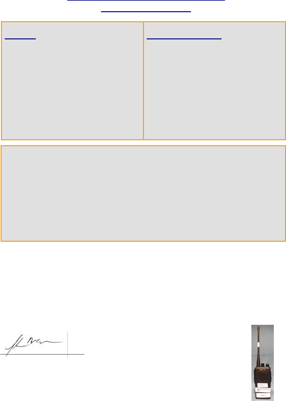
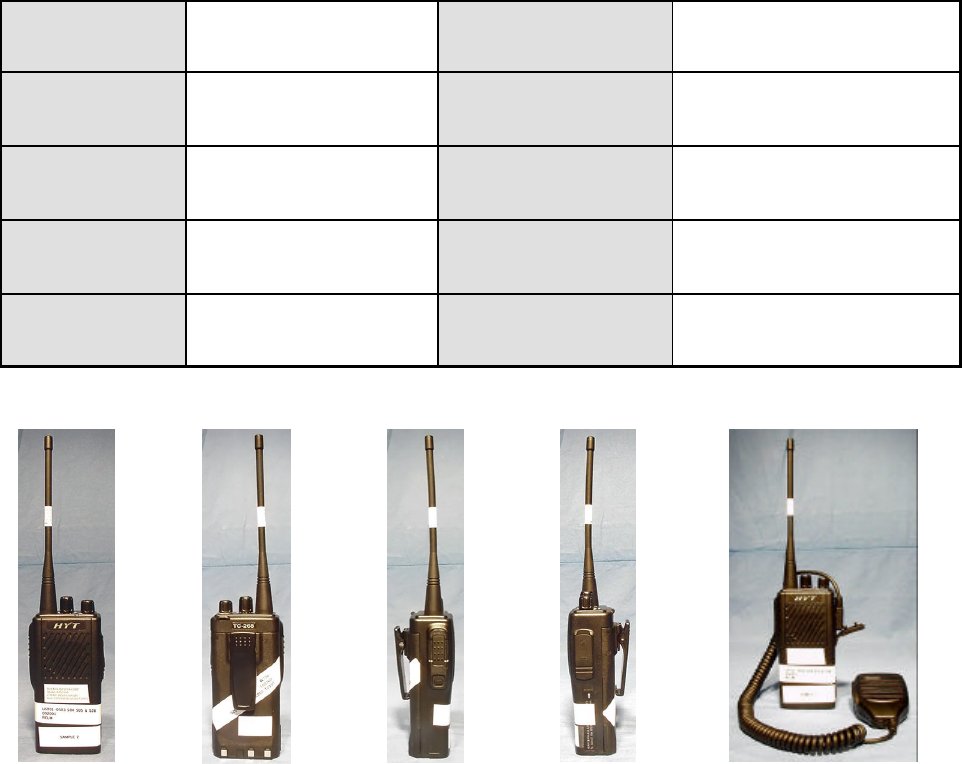
Front of EUT
Back of EUT
Left Side
of EUT
Right Side
of EUT
EUT with Speaker/Mic
CELLTECH RESEARCH INC. Test Report S/N: 092601-169ARU
1955 Moss Court, Kelowna Date of Tests: October 16, 2001
B.C. Canada V1Y 9L3 FCC SAR Evaluation
_________________________________________________________________________________________________________
© 2001 Celltech Research Inc. RELM WIRELESS CORP. FCC ID: ARURPV516A 2
Portable VHF PTT Radio Transceiver (150-174MHz)
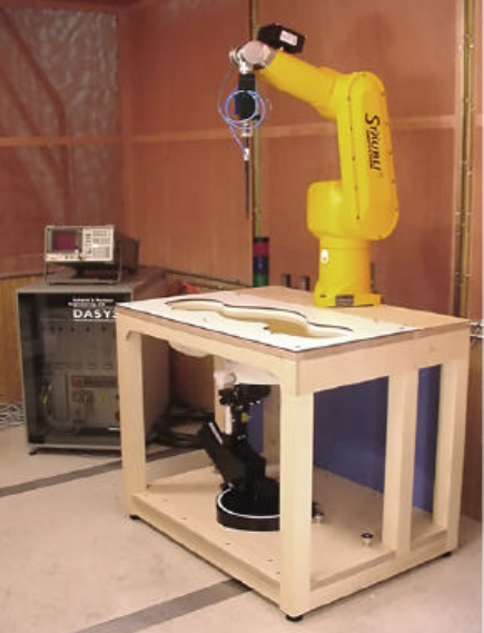
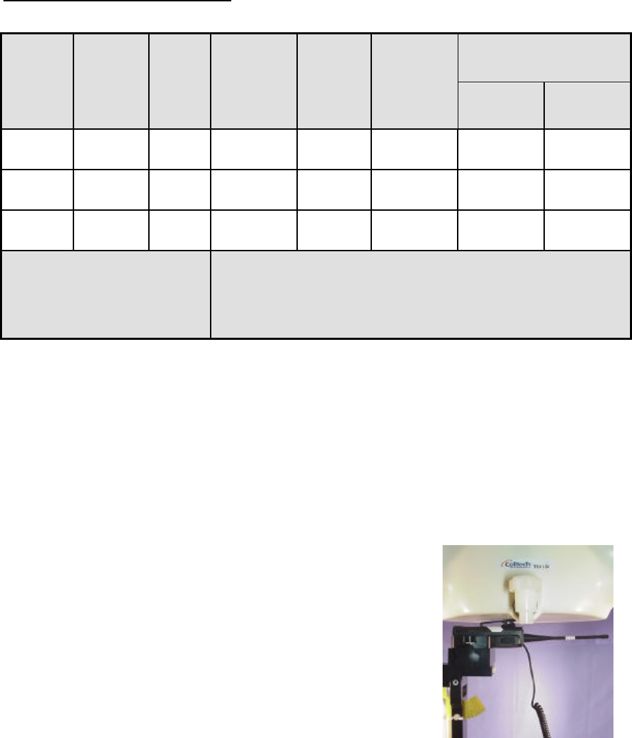
3.0 SAR MEASUREMENT SYSTEM
Celltech Research SAR measurement facility utilizes the Dosimetric Assessment System (DASY™)
manufactured by Schmid & Partner Engineering AG (SPEAG™) of Zurich, Switzerland. The
DASY system is comprised of the robot controller, computer, near-field probe, probe alignment
sensor, and the SAM phantom containing brain or body equivalent material. The robot is a six-axis
industrial robot performing precise movements to position the probe to the location (points) of
maximum electromagnetic field (EMF). A cell controller system contains the power supply, robot
controller, teach pendant (Joystick), and remote control, is used to drive the robot motors. The
Staubli robot is connected to the cell controller to allow software manipulation of the robot. A data
acquisition electronic (DAE) circuit performs the signal amplification, signal multiplexing, AD-
conversion, offset measurements, mechanical surface detection, collision detection, etc. is connected
to the Electro-optical coupler (EOC). The EOC performs the conversion from the optical into digital
electric signal of the DAE and transfers data to the PC plug-in card. The DAE3 utilizes a highly
sensitive electrometer-grade preamplifier with auto-zeroing, a channel and gain-switching
multiplexer, a fast 16-bit AD-converter and a command decoder and control logic unit.
Transmission to the PC-card is accomplished through an optical downlink for data and status
information and an optical uplink for commands and clock lines. The mechanical probe-mounting
device includes two different sensor systems for frontal and sidewise probe contacts. They are also
used for mechanical surface detection and probe collision detection. The robot uses its own controller
with a built in VME-bus computer.
DASY3 SAR Measurement System with SAM phantom
CELLTECH RESEARCH INC. Test Report S/N: 092601-169ARU
1955 Moss Court, Kelowna Date of Tests: October 16, 2001
B.C. Canada V1Y 9L3 FCC SAR Evaluation
_________________________________________________________________________________________________________
© 2001 Celltech Research Inc. RELM WIRELESS CORP. FCC ID: ARURPV516A 3
Portable VHF PTT Radio Transceiver (150-174MHz)
4.0 SAR MEASUREMENT SUMMARY
The measurement results were obtained with the EUT tested in the conditions described in this
report. Detailed measurement data and plots showing the maximum SAR location of the EUT
are reported in Appendix A.
Face-Held SAR Measurements
Notes: 1. The SAR values found were below the maximum limit of 8.0 w/kg (controlled exposure).
2. The highest face-held SAR value found was 0.374 w/kg (100% duty cycle).
3. The EUT was tested for face-held SAR with a 2.5 cm separation distance between the front
of the EUT and the outer surface of the planar phantom.
4. Ambient TEMPERATURE: 23.1 °C
Relative HUMIDITY: 57.3 %
Atmospheric PRESSURE: 100.2 kPa
5. Fluid Temperature ≈ 23 °C
6. During the entire test the conducted power was
maintained to within 5% of the initial conducted
power.
SAR
(w/kg)
Freq.
(MHz) Channel Mode
Conducted
Power
(W)
Antenna
Position
Separation
Distance
(cm) 100%
Duty Cycle 50%
Duty Cycle
150.05 Low CW 5.3 Fixed 2.5 0.374 0.187
162.50 Mid CW 5.3 Fixed 2.5 0.251 0.126
173.95 High CW 5.3 Fixed 2.5 0.138 0.069
Mixture Type: Brain
Dielectric Constant: 52.6
Conductivity: 0.76
ANSI / IEEE C95.1 1992 - SAFETY LIMIT
Spatial Peak Controlled Exposure/Occupational
BRAIN: 8.0 W/kg (averaged over 1 gram)
Face-held SAR Test Setup
2.5cm Separation Distance
CELLTECH RESEARCH INC. Test Report S/N: 092601-169ARU
1955 Moss Court, Kelowna Date of Tests: October 16, 2001
B.C. Canada V1Y 9L3 FCC SAR Evaluation
_________________________________________________________________________________________________________
© 2001 Celltech Research Inc. RELM WIRELESS CORP. FCC ID: ARURPV516A 4
Portable VHF PTT Radio Transceiver (150-174MHz)
Body-Worn SAR Measurements
Notes: 1. The SAR values found were below the maximum limit of 8.0 w/kg (controlled exposure).
2. The highest body-worn SAR value found was 0.965 w/kg (100% duty cycle).
3. The EUT was tested for body-worn SAR with the attached belt-clip providing a 1.4cm
separation distance between the back of the EUT and the outer surface of the planar phantom.
4. Ambient TEMPERATURE: 23.1 °C
Relative HUMIDITY: 57.3 %
Atmospheric PRESSURE: 100.2 kPa
5. Fluid Temperature ≈ 23 °C
6. During the entire test the conducted power was
maintained to within 5% of the initial conducted
power.
SAR
(w/kg)
Freq.
(MHz) Channel Mode
Conducted
Power
(W)
Antenna
Position
Belt-Clip
Separation
Distance
(cm) 100%
Duty Cycle 50%
Duty Cycle
150.05 Low CW 5.3 Fixed 1.4 0.965 0.483
162.50 Mid CW 5.3 Fixed 1.4 0.645 0.323
173.95 High CW 5.3 Fixed 1.4 0.138 0.069
Mixture Type: Body
Dielectric Constant: 62.2
Conductivity: 0.80
ANSI / IEEE C95.1 1992 - SAFETY LIMIT
Spatial Peak Controlled Exposure/Occupational
BODY: 8.0 W/kg (averaged over 1 gram)
Body-worn SAR Test Setup
with 1.4cm Belt-Clip
CELLTECH RESEARCH INC. Test Report S/N: 092601-169ARU
1955 Moss Court, Kelowna Date of Tests: October 16, 2001
B.C. Canada V1Y 9L3 FCC SAR Evaluation
_________________________________________________________________________________________________________
© 2001 Celltech Research Inc. RELM WIRELESS CORP. FCC ID: ARURPV516A 5
Portable VHF PTT Radio Transceiver (150-174MHz)
5.0 DETAILS OF SAR EVALUATION
The RELM WIRELESS CORP. Model: RPV516A Portable VHF PTT Radio Transceiver FCC ID:
ARURPV516A was found to be compliant for localized Specific Absorption Rate (Controlled Exposure)
based on the following test provisions and conditions:
1. The EUT was tested in a face-held configuration with the front of the device placed parallel to the
outer surface of the planar phantom and with a 2.5cm separation distance.
2. The EUT was tested in a body-worn configuration with the attached belt-clip touching the outer
surface of the planar phantom and providing a 1.4cm separation distance between the back of the
EUT and the outer surface of the planar phantom.
3. The EUT was evaluated for SAR at maximum power and the unit was operated for an appropriate
period prior to the evaluation in order to minimize drift. The conducted power level was checked
before and after each test.
4. The conducted power was measured according to the procedures described in FCC Part 2.1046.
5. The location of the maximum spatial SAR distribution (Hot Spot) was determined relative to the
device and its antenna.
6. The EUT was tested with a fully charged battery.
Note: Under continuous transmission the antenna became very warm and began to droop slightly.
The device was cooled for brief periods during the evaluation in order to stabilize the antenna. The
lower than expected SAR values reported for this particular EUT operating at the rated power levels
can be attributed to excessive heating in the plastic antenna housing.
6.0 EVALUATION PROCEDURES
The Specific Absorption Rate (SAR) evaluation was performed in the following manner:
a. (i) The evaluation was performed in the applicable area of the phantom depending on the type of
device being tested. For devices held to the ear during normal operation, both the left and right ear
positions were evaluated in accordance with FCC OET Bulletin 65, Supplement C (Edition 01-01).
(ii) For body-worn and face-held devices the planar section of the phantom was used.
b. The SAR was determined by a pre-defined procedure within the DASY3 software. Upon
completion of a reference and optical surface check, the exposed region of the phantom was
scanned near the inner surface with a grid spacing of 20mm x 20mm.
c. For frequencies below 500MHz a 4x4x7 matrix was performed around the greatest spatial SAR
distribution found during the area scan of the applicable exposed region. For frequencies above
500MHz a 5x5x7 matrix was performed. SAR values were then calculated using a 3-D spline
interpolation algorithm and averaged over spatial volumes of 1 and 10 grams.
d. If the EUT had any appreciable drift over the course of the evaluation, then the EUT was re-
evaluated. Any unusual anomalies over the course of the test also warranted a re-evaluation.
e. The E-field probe conversion factors outside the calibrated points were determined as follows:
• In brain and body tissue between 750MHz and 1GHz, the conversion factor decreases
approximately 1.3% per 100MHz frequency increase.
• In brain and body tissue between 1.6GHz and 2GHz, the conversion factor decreases
approximately 1% per 100MHz frequency increase.
For body tissue around 900MHz (permittivity about 30% higher and conductivity about 15%
higher than brain tissue):
• The conversion factor in body tissue is approximately 3% lower than for brain tissue for the
same frequency.

CELLTECH RESEARCH INC. Test Report S/N: 092601-169ARU
1955 Moss Court, Kelowna Date of Tests: October 16, 2001
B.C. Canada V1Y 9L3 FCC SAR Evaluation
_________________________________________________________________________________________________________
© 2001 Celltech Research Inc. RELM WIRELESS CORP. FCC ID: ARURPV516A 6
Portable VHF PTT Radio Transceiver (150-174MHz)
7.0 SYSTEM VALIDATION
Prior to the assessment, the system was verified in the planar section of the phantom with a 900MHz
dipole for devices operating below 1GHz, and an 1800MHz dipole for devices operating above 1GHz. A
forward power of 250mW was applied to the dipole and system was verified to a tolerance of +10%. The
applicable verifications are as follows (see Appendix B for validation test plot):
8.0 TISSUE PARAMETERS
The dielectric parameters of the fluids were verified prior to the SAR evaluation using an 85070C
Dielectric Probe Kit and an 8753E Network Analyzer. The dielectric parameters of the fluid are as
follows:
Dipole Validation Kit Target SAR 1g (w/kg) Measured
SAR 1g (w/kg)
D900V2 2.78 2.76
TISSUE PARAMETERS FOR DIPOLE VALIDATION
Brain Equivalent Tissue Dielectric Constant
εεr Conductivity
σσ (mho/m) ρρ (Kg/m3)
900MHz (Target) 41.5 ±5% 0.97 ±5% 1000
900MHz (Measured)
10/16/01 42.4 0.97 1000
BRAIN TISSUE PARAMETERS - EUT EVALUATION
Equivalent Tissue Dielectric Constant
εεr Conductivity
σσ (mho/m) ρρ (Kg/m3)
150MHz Brain
(Target) 52.3 ±5% 0.76 ±5% 1000
150MHz Brain
(Measured: 10/16/01) 52.6 0.76 1000
BODY TISSUE PARAMETERS - EUT EVALUATION
Equivalent Tissue Dielectric Constant
εεr Conductivity
σσ (mho/m) ρρ (Kg/m3)
150MHz Body
(Target) 61.9 ±5% 0.80 ±5% 1000
150MHz Body
(Measured: 10/16/01) 62.2 0.80 1000

CELLTECH RESEARCH INC. Test Report S/N: 092601-169ARU
1955 Moss Court, Kelowna Date of Tests: October 16, 2001
B.C. Canada V1Y 9L3 FCC SAR Evaluation
_________________________________________________________________________________________________________
© 2001 Celltech Research Inc. RELM WIRELESS CORP. FCC ID: ARURPV516A 7
Portable VHF PTT Radio Transceiver (150-174MHz)
9.0 SIMULATED TISSUES
The brain and body mixtures consist of a viscous gel using hydroxethylcellulose (HEC) gelling agent
and saline solution. Preservation with a bactericide is added and visual inspection is made to ensure air
bubbles are not trapped during the mixing process. The fluid was prepared according to standardized
procedures and measured for dielectric parameters (permitivity and conductivity).
10.0 SAR SAFETY LIMITS
Notes:
1. Uncontrolled environments are defined as locations where there is potential exposure of
individuals who have no knowledge or control of their potential exposure.
2. Controlled environments are defined as locations where there is potential exposure of
individuals who have knowledge of their potential exposure and can exercise control over
their exposure.
SAR (W/Kg)
EXPOSURE LIMITS (General Population /
Uncontrolled Exposure
Environment)
(Occupational /
Controlled Exposure
Environment)
Spatial Average
(averaged over the whole body) 0.08 0.4
Spatial Peak
(averaged over any 1g of tissue) 1.60 8.0
Spatial Peak
(hands/wrists/feet/ankles
averaged over 10g) 4.0 20.0
MIXTURE %
INGREDIENT 900MHz Brain
(Validation) 150MHz Brain 150MHz Body
Water 51.07 38.35 46.6
Sugar 47.31 55.5 49.7
Salt 1.15 5.15 2.6
HEC 0.23 0.9 1.0
Bactericide 0.24 0.1 0.1

CELLTECH RESEARCH INC. Test Report S/N: 092601-169ARU
1955 Moss Court, Kelowna Date of Tests: October 16, 2001
B.C. Canada V1Y 9L3 FCC SAR Evaluation
_________________________________________________________________________________________________________
© 2001 Celltech Research Inc. RELM WIRELESS CORP. FCC ID: ARURPV516A 8
Portable VHF PTT Radio Transceiver (150-174MHz)
11.0 ROBOT SYSTEM SPECIFICATIONS
Specifications
POSITIONER: Stäubli Unimation Corp. Robot Model: RX60L
Repeatability: 0.02 mm
No. of axis: 6
Data Acquisition Electronic (DAE) System
Cell Controller
Processor: Pentium III
Clock Speed: 450 MHz
Operating System: Windows NT
Data Card: DASY3 PC-Board
Data Converter
Features: Signal Amplifier, multiplexer, A/D converter, and control logic
Software: DASY3 software
Connecting Lines: Optical downlink for data and status info.
Optical uplink for commands and clock
PC Interface Card
Function: 24 bit (64 MHz) DSP for real time processing
Link to DAE3
16-bit A/D converter for surface detection system
serial link to robot
direct emergency stop output for robot
E-Field Probe
Model: ET3DV6
Serial No.: 1590
Construction: Triangular core fiber optic detection system
Frequency: 10 MHz to 6 GHz
Linearity: ± 0.2 dB (30 MHz to 3 GHz)
Phantom
Type: SAM V4.0C
Shell Material: Fiberglass
Thickness: 2.0 ± 0.1 mm
Volume: Approx. 20 liters
CELLTECH RESEARCH INC. Test Report S/N: 092601-169ARU
1955 Moss Court, Kelowna Date of Tests: October 16, 2001
B.C. Canada V1Y 9L3 FCC SAR Evaluation
_________________________________________________________________________________________________________
© 2001 Celltech Research Inc. RELM WIRELESS CORP. FCC ID: ARURPV516A 9
Portable VHF PTT Radio Transceiver (150-174MHz)
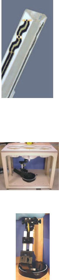
ET3DV6 E-Field Probe
12.0 PROBE SPECIFICATION (ET3DV6)
Construction: Symmetrical design with triangular core
Built-in shielding against static charges
PEEK enclosure material (resistant to organic solvents, e.g. glycol)
Calibration: In air from 10 MHz to 2.5 GHz
In brain simulating tissue at frequencies of 900 MHz
and 1.8 GHz (accuracy ± 8%)
Frequency: 10 MHz to > 6 GHz; Linearity: ± 0.2 dB
(30 MHz to 3 GHz)
Directivity: ± 0.2 dB in brain tissue (rotation around probe axis)
± 0.4 dB in brain tissue (rotation normal to probe axis)
Dynam. Rnge: 5 µW/g to > 100 mW/g; Linearity: ± 0.2 dB
Srfce. Detect. ± 0.2 mm repeatability in air and clear liquids over
diffuse reflecting surfaces
Dimensions: Overall length: 330 mm
Tip length: 16 mm
Body diameter: 12 mm
Tip diameter: 6.8 mm
Distance from probe tip to dipole centers: 2.7 mm
Application: General dosimetry up to 3 GHz
Compliance tests of mobile phone
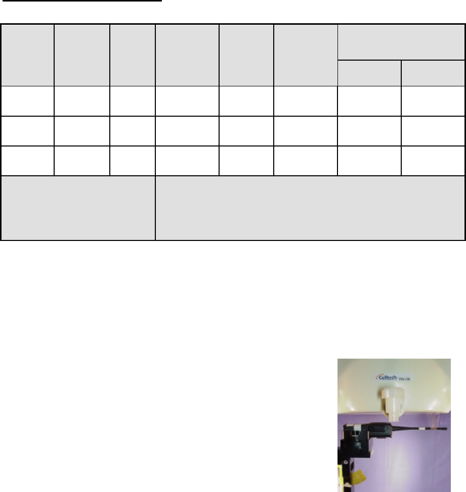
13.0 SAM PHANTOM V4.0C
The SAM phantom V4.0C is a fiberglass shell phantom with a 2.0mm
shell thickness for left and right head and flat planar area integrated in a
wooden table. The shape of the fiberglass shell corresponds to the
phantom defined by SCC34-SC2. The device holder positions are
adjusted to the standard measurement positions in the three sections.
14.0 DEVICE HOLDER
The DASY3 device holder has two scales for device rotation (with respect
to the body axis) and the device inclination (with respect to the line
between the ear openings). The plane between the ear openings and the
mouth tip has a rotation angle of 65°. The bottom plate contains three pair
of bolts for locking the device holder. The device holder positions are
adjusted to the standard measurement positions in the three sections.
SAM Phantom
Device Holder

CELLTECH RESEARCH INC. Test Report S/N: 092601-169ARU
1955 Moss Court, Kelowna Date of Tests: October 16, 2001
B.C. Canada V1Y 9L3 FCC SAR Evaluation
_________________________________________________________________________________________________________
© 2001 Celltech Research Inc. RELM WIRELESS CORP. FCC ID: ARURPV516A 10
Portable VHF PTT Radio Transceiver (150-174MHz)
15.0 TEST EQUIPMENT LIST
SAR MEASUREMENT SYSTEM
EQUIPMENT
SERIAL NO.
CALIBRATION DATE
DASY3 System
-Robot
-ET3DV6 E-Field Probe
-DAE
-900MHz Validation Dipole
-1800MHz Validation Dipole
-SAM Phantom V4.0C
599396-01
1590
370
054
247
N/A
N/A
Mar 2001
Sept 1999
June 2001
June 2001
N/A
85070C Dielectric Probe Kit
N/A
N/A
Gigatronics 8652A Power Meter
-Power Sensor 80701A
-Power Sensor 80701A
1835272
1833535
1833542
Oct 1999
Jan 2001
Feb 2001
E4408B Spectrum Analyzer
US39240170
Nov 1999
8594E Spectrum Analyzer
3543A02721
Mar 2000
8753E Network Analyzer
US38433013
Nov 1999
8648D Signal Generator
3847A00611
N/A
5S1G4 Amplifier Research Power Amplifier
26235
N/A

CELLTECH RESEARCH INC. Test Report S/N: 092601-169ARU
1955 Moss Court, Kelowna Date of Tests: October 16, 2001
B.C. Canada V1Y 9L3 FCC SAR Evaluation
_________________________________________________________________________________________________________
© 2001 Celltech Research Inc. RELM WIRELESS CORP. FCC ID: ARURPV516A 11
Portable VHF PTT Radio Transceiver (150-174MHz)
16.0 MEASUREMENT UNCERTAINTIES
Uncertainty Description Error Distribution Weight Standard
Deviation Offset
Probe Uncertainty
Axial isotropy ±0.2 dB U-Shaped 0.5 ±2.4 %
Spherical isotropy ±0.4 dB U-Shaped 0.5 ±4.8 %
Isotropy from gradient ±0.5 dB U-Shaped 0 ±
Spatial resolution ±0.5 % Normal 1 ±0.5 %
Linearity error ±0.2 dB Rectangle 1 ±2.7 %
Calibration error ±3.3 % Normal 1 ±3.3 %
SAR Evaluation Uncertainty
Data acquisition error ±1 % Rectangle 1 ±0.6 %
ELF and RF disturbances ±0.25 % Normal 1 ±0.25 %
Conductivity assessment ±5 % Rectangle 1 ±5.8 %
Spatial Peak SAR Evaluation
Uncertainty
Extrapolated boundary effect ±3 % Normal 1 ±3 % ±5 %
Probe positioning error ±0.1 mm Normal 1 ±1 %
Integrated and cube orientation ±3 % Normal 1 ±3 %
Cube Shape inaccuracies ±2 % Rectangle 1 ±1.2 %
Device positioning ±6 % Normal 1 ±6 %
Combined Uncertainties ±11.7 % ±5 %
Measurement uncertainties in SAR measurements are difficult to quantify due to several
variables including biological, physiological, and environmental.
According to ANSI/IEEE C95.3, the overall uncertainties are difficult to assess and will vary
with the type of meter and usage situation. However, accuracy’s of ± 1 to 3 dB can be expected
in practice, with greater uncertainties in near-field situations and at higher frequencies (shorter
wavelengths), or areas where large reflecting objects are present. Under optimum measurement
conditions, SAR measurement uncertainties of at least ± 2dB can be expected.
According to CENELEC, typical worst-case uncertainty of field measurements is ± 5 dB.
For well-defined modulation characteristics the uncertainty can be reduced to ± 3 dB.
CELLTECH RESEARCH INC. Test Report S/N: 092601-169ARU
1955 Moss Court, Kelowna Date of Tests: October 16, 2001
B.C. Canada V1Y 9L3 FCC SAR Evaluation
_________________________________________________________________________________________________________
© 2001 Celltech Research Inc. RELM WIRELESS CORP. FCC ID: ARURPV516A 12
Portable VHF PTT Radio Transceiver (150-174MHz)
17.0 REFERENCES
(1) ANSI, ANSI/IEEE C95.1: IEEE Standard for Safety Levels with Respect to Human Exposure
to Radio Frequency Electromagnetic Fields, 3kHz to 300 Ghz, The Institute of Electrical and
Electronics Engineers, Inc., New York, NY: 1992.
(2) Federal Communications Commission, “Evaluating Compliance with FCC Guidelines for
Human Exposure to Radio frequency Electromagnetic Fields”, OET Bulletin 65, Supplement C
(Edition 01-01), FCC, Washington, D.C. 20554: June 2001.
(3) Thomas Schmid, Oliver Egger, and Neils Kuster, “Automated E-field scanning system for
dosimetric assessments”, IEEE Transaction on Microwave Theory and Techniques, Vol. 44, pp.
105 – 113: January 1996.
(4) Niels Kuster, Ralph Kastle, and Thomas Schmid, “Dosimetric evaluation of mobile
communications equipment with know precision”, IEICE Transactions of Communications, vol.
E80-B, no. 5, pp. 645 – 652: May 1997.
CELLTECH RESEARCH INC. Test Report S/N: 092601-169ARU
1955 Moss Court, Kelowna Date of Tests: October 16, 2001
B.C. Canada V1Y 9L3 FCC SAR Evaluation
_________________________________________________________________________________________________________
© 2001 Celltech Research Inc. RELM WIRELESS CORP. FCC ID: ARURPV516A 13
Portable VHF PTT Radio Transceiver (150-174MHz)
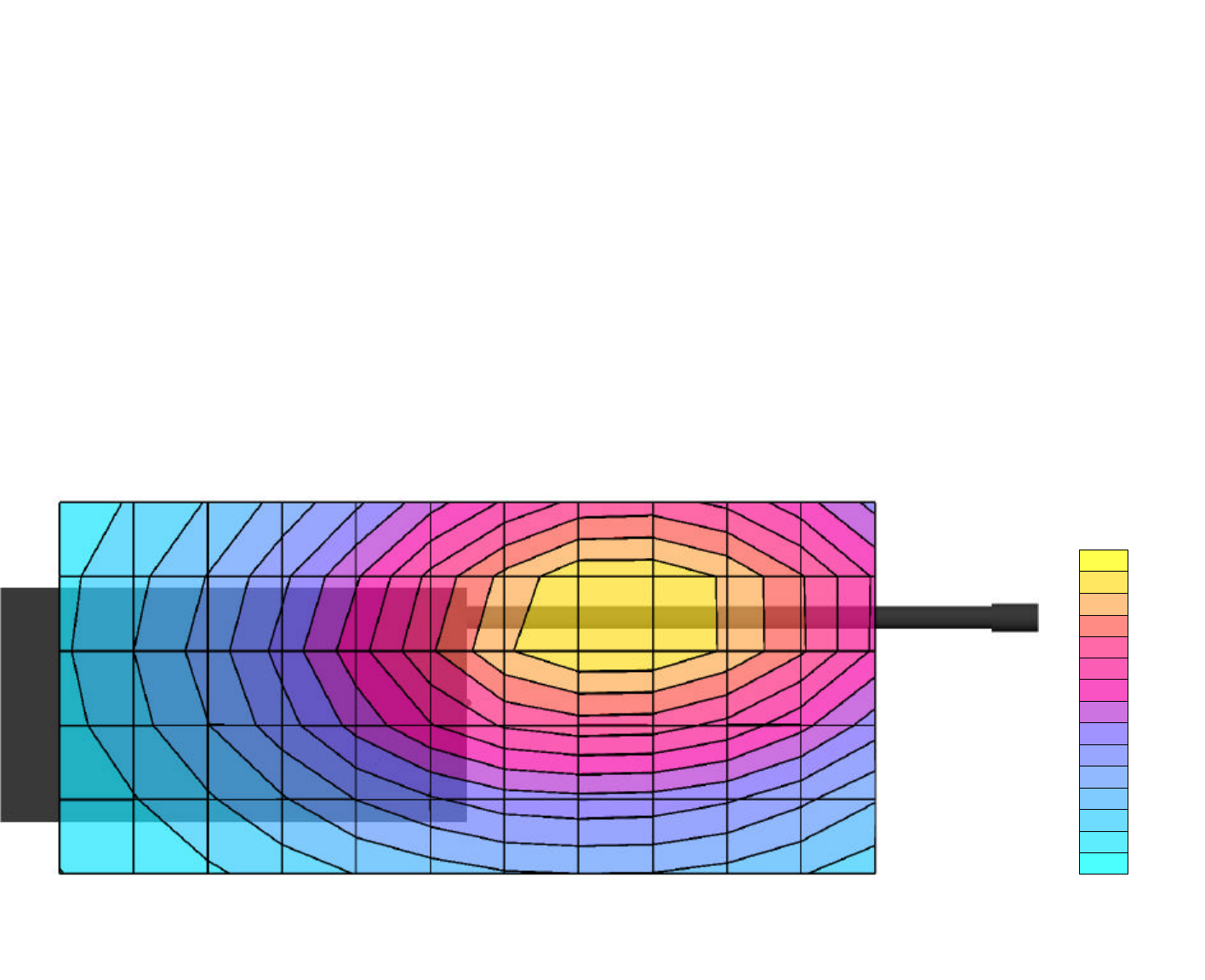
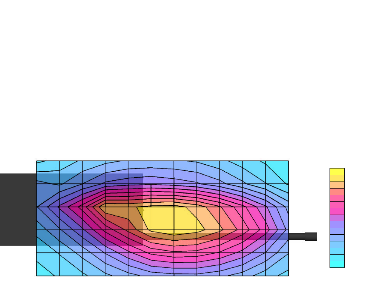
APPENDIX A - SAR MEASUREMENT DATA
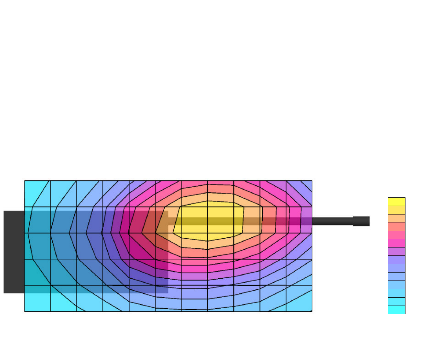
RELM Wireless Corporation FCC ID: ARURPV516A
SAM Phantom; Flat Section; Position: (90°,90°)
Probe: ET3DV6 - SN1590; ConvF(7.71,7.71,7.71); Crest factor: 1.0
150 MHz Brain :
σ
= 0.76 mho/m ε
r
= 52.3
ρ
= 1.00 g/cm3
Coarse: Dx = 20.0, Dy = 20.0, Dz = 10.0
Cube 4x4x7
SAR (1g): 0.374 mW/g, SAR (10g): 0.282 mW/g
Face SAR at 2.5 cm Separation Distance
Relm Wireless Model: RPV516A
Continuous Wave Mode
Low Channel (150.05 MHz)
Conducted Power: 5.3 Watts
Date Tested: October 16, 2001
SARTot [mW/g]
2.81E-2
8.42E-2
1.40E-1
1.97E-1
2.53E-1
3.09E-1
3.65E-1
Celltech Research Inc.
Celltech Research Inc.
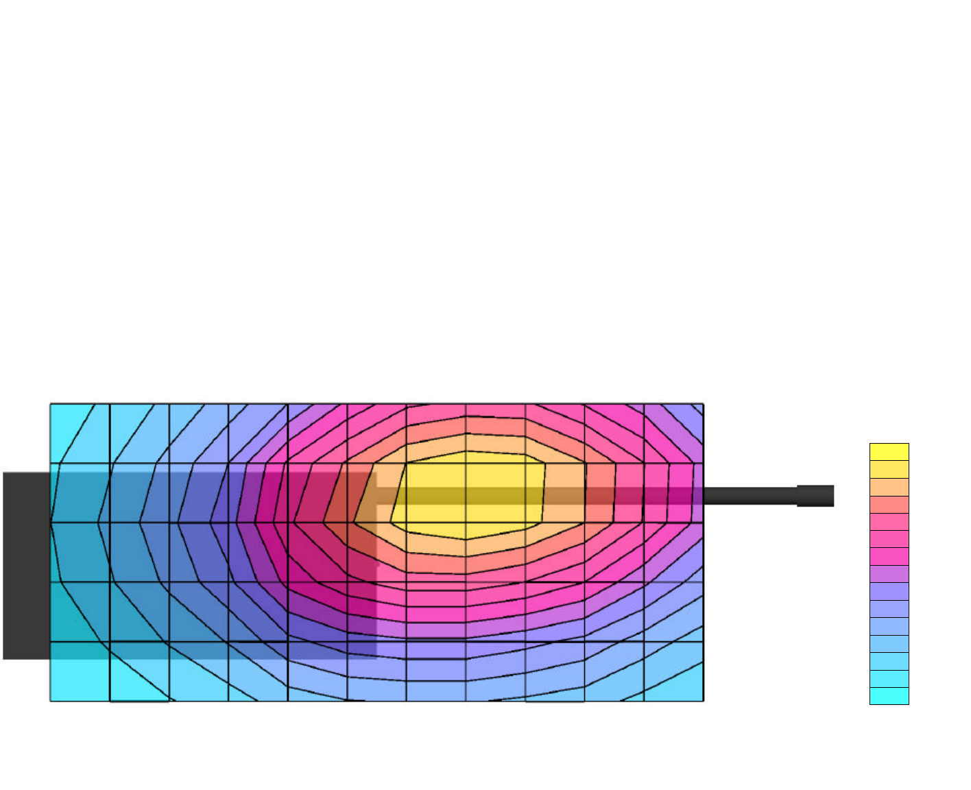
RELM Wireless Corporation FCC ID: ARURPV516A
SAM Phantom; Flat Section; Position: (90°,90°)
Probe: ET3DV6 - SN1590; ConvF(7.71,7.71,7.71); Crest factor: 1.0
150 MHz Brain :
σ
= 0.76 mho/m ε
r
= 52.3
ρ
= 1.00 g/cm3
Coarse: Dx = 20.0, Dy = 20.0, Dz = 10.0
Cube 4x4x7
SAR (1g): 0.251 mW/g , SAR (10g): 0.187 mW/g
Face SAR at 2.5 cm Separation Distance
Relm Wireless Model: RPV516A
Continuous Wave Mode
Mid Channel (162.50 MHz)
Conducted Power: 5.3 Watts
Date Tested: October 16, 2001
SARTot [mW/g]
1.89E-2
5.66E-2
9.43E-2
1.32E-1
1.70E-1
2.07E-1
2.45E-1
Celltech Research Inc.
Celltech Research Inc.
RELM Wireless Corporation FCC ID: ARURPV516A
SAM Phantom; Flat Section; Position: (90°,90°)
Probe: ET3DV6 - SN1590; ConvF(7.71,7.71,7.71); Crest factor: 1.0
150 MHz Brain :
σ
= 0.76 mho/m ε
r
= 52.3
ρ
= 1.00 g/cm3
Coarse: Dx = 20.0, Dy = 20.0, Dz = 10.0
Cube 4x4x7
SAR (1g): 0.138 mW/g, SAR (10g): 0.104 mW/g
Face SAR at 2.5 cm Separation Distance
Relm Wireless Model: RPV516A
Continuous Wave Mode
High Channel (173.95 MHz)
Conducted Power: 5.3 Watts
Date Tested: October 16, 2001
SARTot [mW/g]
9.29E-3
2.79E-2
4.64E-2
6.50E-2
8.36E-2
1.02E-1
1.21E-1
Celltech Research Inc.
Celltech Research Inc.
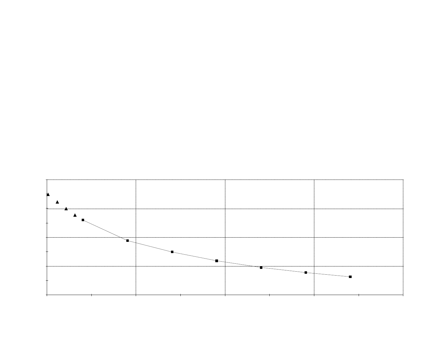
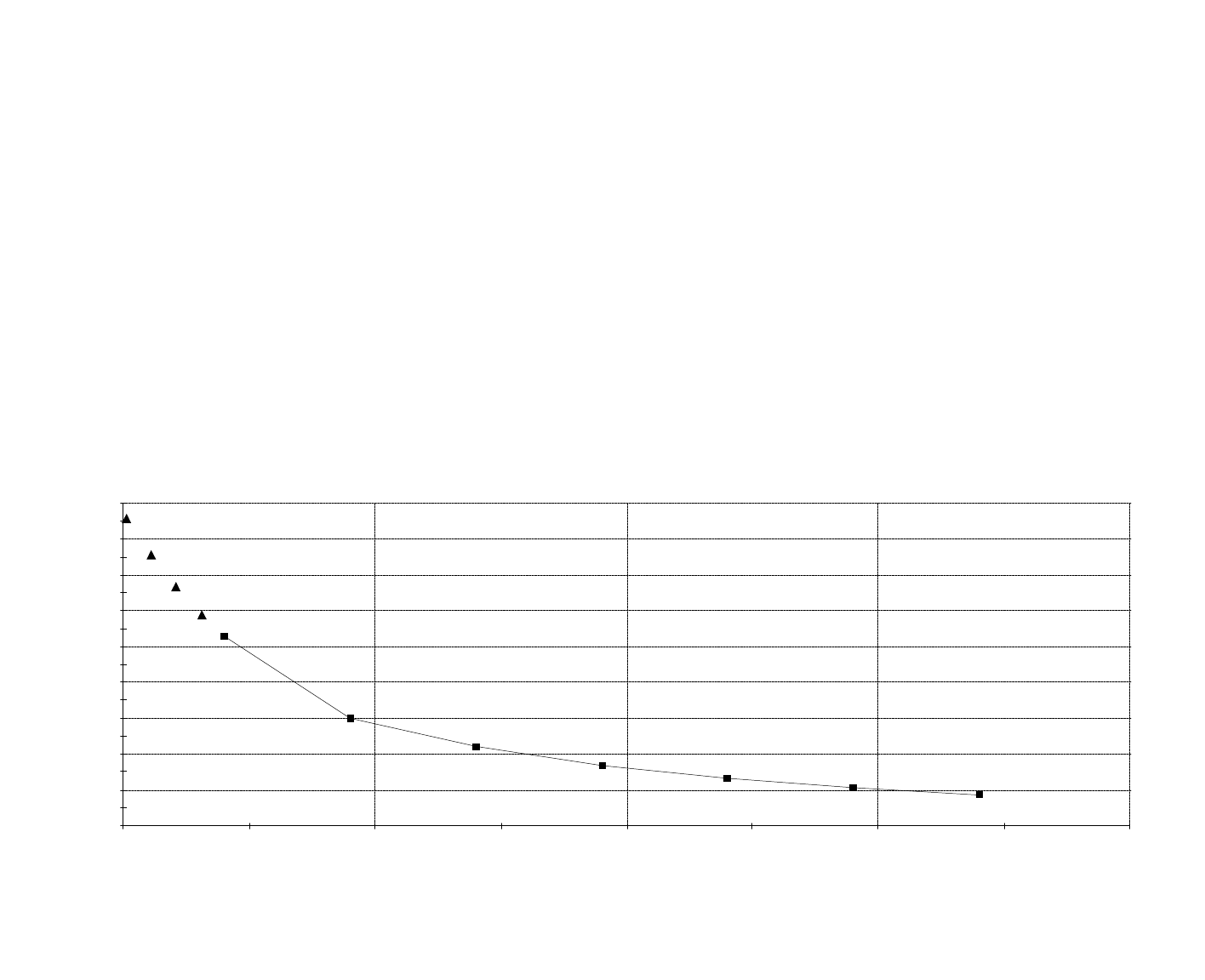
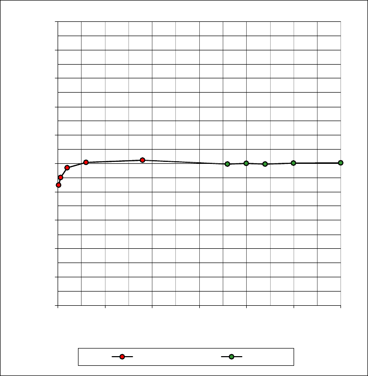
RELM Wireless Corporation FCC ID: ARURPV516A
SAM Phantom; Flat Section
Probe: ET3DV6 - SN1590; ConvF(7.71,7.71,7.71); Crest factor: 1.0
150 MHz Brain :
σ
= 0.76 mho/m ε
r
= 52.3
ρ
= 1.00 g/cm3
Cube 4x4x7
Z-Axis Extrapolation at Peak SAR Location
Face SAR at 2.5 cm Separation Distance
Relm Wireless Model: RPV516A
Continuous Wave Mode
Low Channel (150.05 MHz)
Conducted Power: 5.3 Watts
Date Tested: October 16, 2001
10/16/01
Celltech Research Inc.
0.00
0.10
0.20
0.30
0.40
0 10 20 30 40
SAR tot [mW/g]
[mm]
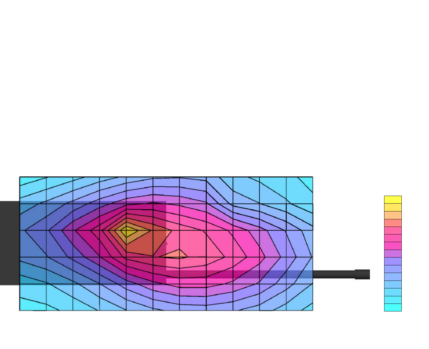
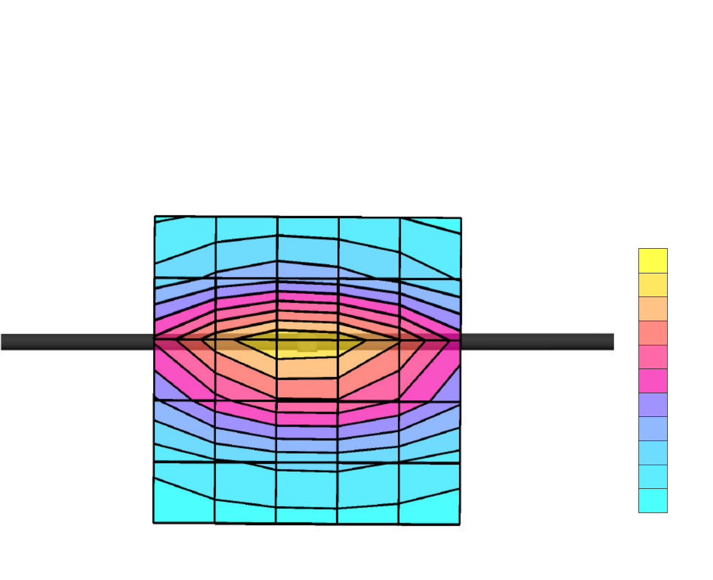
RELM Wireless Corporation FCC ID: ARURPV516A
SAM Phantom; Flat Section; Position: (270°,270°)
Probe: ET3DV6 - SN1590; ConvF(7.65,7.65,7.65); Crest factor: 1.0
150 MHz Muscle:
σ
= 0.80 mho/m ε
r
= 61.9
ρ
= 1.00 g/cm3
Coarse: Dx = 20.0, Dy = 20.0, Dz = 10.0
Cube 4x4x7
SAR (1g): 0.965 mW/g, SAR (10g): 0.612 mW/g
Body SAR with 1.4 cm Belt-Clip Separation
Relm Wireless Model: RPV516A
Continuous Wave Mode
Low Channel (150.05 MHz)
Conducted Power: 5.3 Watts
Date Tested: October 16, 2001
SARTot [mW/g]
6.86E-2
2.06E-1
3.43E-1
4.80E-1
6.17E-1
7.54E-1
8.91E-1
Celltech Research Inc.
Celltech Research Inc.
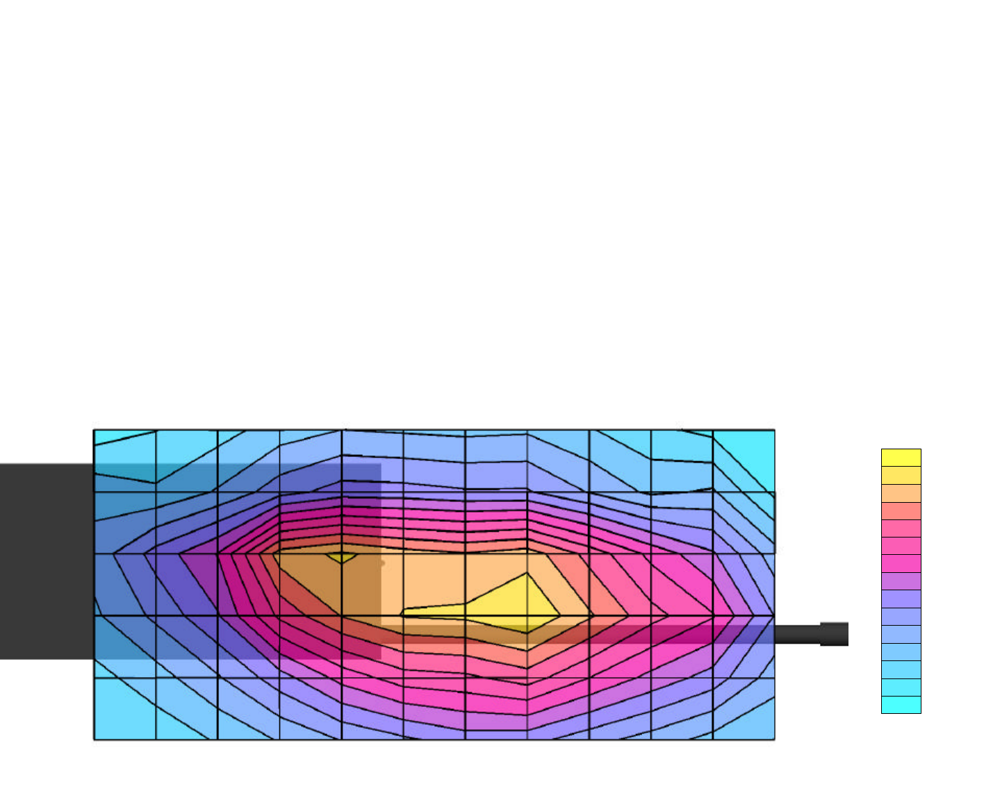
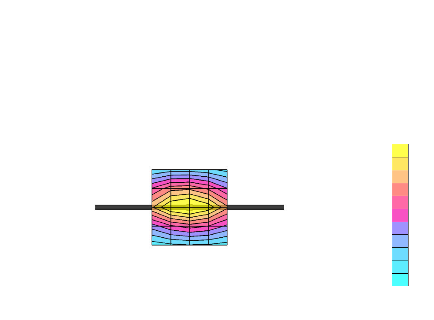
RELM Wireless Corporation FCC ID: ARURPV516A
SAM Phantom; Flat Section; Position: (270°,270°)
Probe: ET3DV6 - SN1590; ConvF(7.65,7.65,7.65); Crest factor: 1.0
150 MHz Muscle:
σ
= 0.80 mho/m ε
r
= 61.9
ρ
= 1.00 g/cm3
Coarse: Dx = 20.0, Dy = 20.0, Dz = 10.0
Cube 4x4x7
SAR (1g): 0.645 mW/g, SAR (10g): 0.468 mW/g
Body SAR with 1.4 cm Belt-Clip Separation
Relm Wireless Model: RPV516A
Continuous Wave Mode
Mid Channel (162.50 MHz)
Conducted Power: 5.3 Watts
Date Tested: October 16, 2001
SARTot [mW/g]
4.89E-2
1.47E-1
2.45E-1
3.42E-1
4.40E-1
5.38E-1
6.36E-1
Celltech Research Inc.
Celltech Research Inc.
RELM Wireless Corporation FCC ID: ARURPV516A
SAM Phantom; Flat Section; Position: (270°,270°)
Probe: ET3DV6 - SN1590; ConvF(7.65,7.65,7.65); Crest factor: 1.0
150 MHz Muscle:
σ
= 0.80 mho/m ε
r
= 61.9
ρ
= 1.00 g/cm3
Coarse: Dx = 20.0, Dy = 20.0, Dz = 10.0
Cube 4x4x7
SAR (1g): 0.138 mW/g , SAR (10g): 0.103 mW/g
Body SAR with 1.4 cm Belt-Clip Separation
Relm Wireless Model: RPV516A
Continuous Wave Mode
High Channel (173.95 MHz)
Conducted Power: 5.3 Watts
Date Tested: October 16, 2001
SARTot [mW/g]
1.01E-2
3.04E-2
5.07E-2
7.10E-2
9.13E-2
1.12E-1
1.32E-1
Celltech Research Inc.
Celltech Research Inc.
RELM Wireless Corporation FCC ID: ARURPV516A
SAM Phantom; Flat Section
Probe: ET3DV6 - SN1590; ConvF(7.65,7.65,7.65); Crest factor: 1.0;
150 MHz Muscle:
σ
= 0.80 mho/m ε
r
= 61.9
ρ
= 1.00 g/cm3
Cube 4x4x7
Z-Axis Extrapolation at Peak SAR Location
Body SAR with 1.4 cm Belt-Clip Separation
Relm Wireless Model: RPV516A
Continuous Wave Mode
Low Channel (150.05 MHz)
Conducted Power: 5.3 Watts
Date Tested: October 16, 2001
11/16/01
Celltech Research Inc.
0.0
0.2
0.4
0.6
0.8
1.0
1.2
1.4
1.6
1.8
0 10 20 30 40
SAR tot [mW/g]
[mm]
CELLTECH RESEARCH INC. Test Report S/N: 092601-169ARU
1955 Moss Court, Kelowna Date of Tests: October 16, 2001
B.C. Canada V1Y 9L3 FCC SAR Evaluation
_________________________________________________________________________________________________________
© 2001 Celltech Research Inc. RELM WIRELESS CORP. FCC ID: ARURPV516A 14
Portable VHF PTT Radio Transceiver (150-174MHz)
APPENDIX B - DIPOLE VALIDATION
Dipole 900 MHz
SAM Phantom; Flat Section; - Validation Date: October 16, 2001
Probe: ET3DV6 - SN1590; ConvF(6.83,6.83,6.83); Crest factor: 1.0; Brain 900 MHz:
σ
= 0.97 mho/m ε
r
= 42.4
ρ
= 1.00 g/cm3
Cubes (2): Peak: 4.47 mW/g ± 0.00 dB, SAR (1g): 2.76 mW/g ± 0.00 dB, SAR (10g): 1.74 mW/g ± 0.00 dB, (Worst-case extrapolation)
Penetration depth: 11.5 (10.4, 12.9) [mm]
Powerdrift: -0.02 dB
SARTot [mW/g]
2.96E-1
5.93E-1
8.91E-1
1.17E+0
1.478E+0
1.77E+0
2.06E+0
2.36E+0
2.66E+0
2.96E+0
Celltech Research Inc.
Celltech Research Inc.
Validation Dipole D900V2 SN:054, d = 15 mm
Frequency: 900 MHz; Antenna Input Power: 250 [mW]
Generic Twin Phantom; Flat Section; Grid Spacing:Dx = 15.0, Dy = 15.0, Dz = 10.0
Probe: ET3DV6 - SN1507; ConvF(6.27,6.27,6.27); Crest factor: 1.0; IEEE1528 900 MHz: σ = 0.97 mho/m ε
r
= 42.4 ρ = 1.00 g/cm3
Cubes (2): Peak: 4.47 mW/g ± 0.05 dB, SAR (1g): 2.78 mW/g ± 0.04 dB, SAR (10g): 1.76 mW/g ± 0.02 dB, (Worst-case extrapolation)
Penetration depth: 11.5 (10.3, 13.2) [mm]
Powerdrift: -0.00 dB
SARTot [mW/g]
2.50E-1
5.00E-1
7.50E-1
1.00E+0
1.25E+0
1.50E+0
1.75E+0
2.00E+0
2.25E+0
2.50E+0
06/19/01
Schmid & Partner Engineering AG, Zurich, Switzerland
CELLTECH RESEARCH INC. Test Report S/N: 092601-169ARU
1955 Moss Court, Kelowna Date of Tests: October 16, 2001
B.C. Canada V1Y 9L3 FCC SAR Evaluation
_________________________________________________________________________________________________________
© 2001 Celltech Research Inc. RELM WIRELESS CORP. FCC ID: ARURPV516A 15
Portable VHF PTT Radio Transceiver (150-174MHz)
APPENDIX C - PROBE CALIBRATION
Probe ET3DV6
SN:1590
Manufactured: March 19, 2001
Calibrated: March 26, 2001
Calibrated for System DASY3
Page 1 of 8
ET3DV6 SN:1590
DASY3 - Parameters of Probe: ET3DV6 SN:1590
Sensitivity in Free Space Diode Compression
NormX 1.77 µV/(V/m)2DCP X 100 mV
NormY 1.91 µV/(V/m)2DCP Y 100 mV
NormZ 1.67 µV/(V/m)2DCP Z 100 mV
Sensitivity in Tissue Simulating Liquid
Head 450 MHz ε
r
=43.5 ± 5% σ =0.87 ± 10% mho/m
ConvF X 7.36 extrapolated Boundary effect:
ConvF Y 7.36 extrapolated Alpha 0.29
ConvF Z 7.36 extrapolated Depth 2.72
Head 900 MHz ε
r
=42 ± 5% σ =0.97 ± 10% mho/m
ConvF X 6.83 ± 7% (k=2) Boundary effect:
ConvF Y 6.83 ± 7% (k=2) Alpha 0.37
ConvF Z 6.83 ± 7% (k=2) Depth 2.48
Head 1500 MHz ε
r
=40.4 ± 5% σ =1.23 ± 10% mho/m
ConvF X 6.13 interpolated Boundary effect:
ConvF Y 6.13 interpolated Alpha 0.47
ConvF Z 6.13 interpolated Depth 2.17
Head 1800 MHz ε
r
=40 ± 5% σ =1.40 ± 10% mho/m
ConvF X 5.78 ± 7% (k=2) Boundary effect:
ConvF Y 5.78 ± 7% (k=2) Alpha 0.53
ConvF Z 5.78 ± 7% (k=2) Depth 2.01
Sensor Offset
Probe Tip to Sensor Center 2.7 mm
Optical Surface Detection 1.2 ± 0.2 mm
Page 2 of 8
ET3DV6 SN:1590
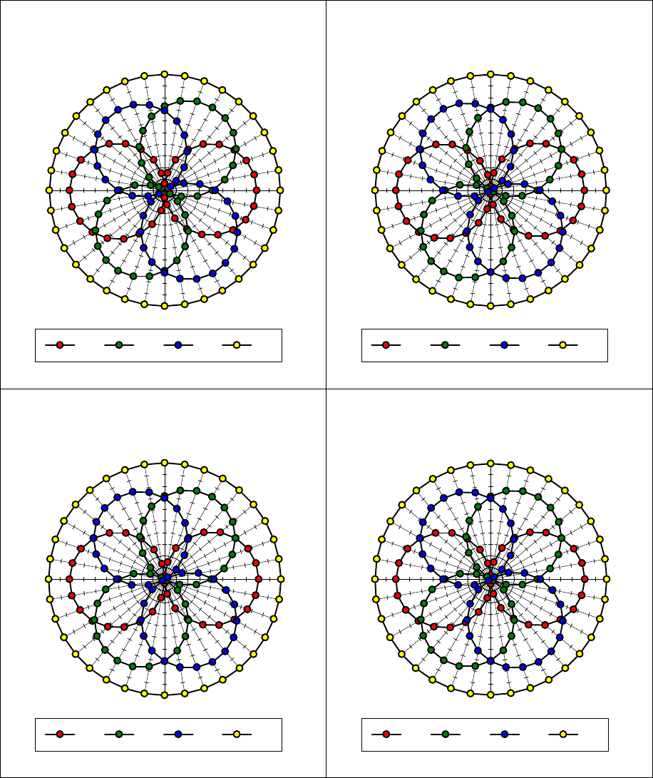
Receiving Pattern (φ), θ = 0°
f = 30 MHz, TEM cell ifi110
010 20 30
40
50
60
70
80
90
100
110
120
130
140
150
160
170
180
190
200
210
220
230
240
250
260
270
280
290
300
310
320
330 340 350
XYZTot
f = 100 MHz, TEM cell ifi110
010 20 30
40
50
60
70
80
90
100
110
120
130
140
150
160
170
180
190
200
210
220
230
240
250
260
270
280
290
300
310
320
330 340 350
XYZTot
f = 300 MHz, TEM cell ifi110
010 20 30
40
50
60
70
80
90
100
110
120
130
140
150
160
170
180
190
200
210
220
230
240
250
260
270
280
290
300
310
320
330 340 350
XYZTot
f = 900 MHz, TEM cell ifi110
010 20 30
40
50
60
70
80
90
100
110
120
130
140
150
160
170
180
190
200
210
220
230
240
250
260
270
280
290
300
310
320
330 340 350
XYZTot
Page 3 of 8
ET3DV6 SN:1590
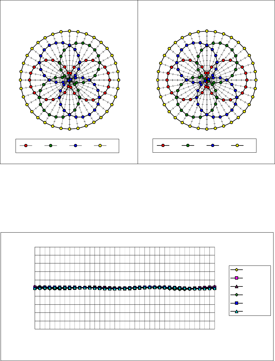
Isotropy Error (φ ), θ = 0°
-1.00
-0.80
-0.60
-0.40
-0.20
0.00
0.20
0.40
0.60
0.80
1.00
0 60 120 180 240 300 360
error[dB]
30 MHz
100 MHz
300 MHz
900 MHz
1800 MHz
2500 MHz
f = 1800 MHz, WG R22
010 20 30
40
50
60
70
80
90
100
110
120
130
140
150
160
170
180
190
200
210
220
230
240
250
260
270
280
290
300
310
320
330 340 350
XYZTot
f = 2500 MHz, WG R26
010 20 30
40
50
60
70
80
90
100
110
120
130
140
150
160
170
180
190
200
210
220
230
240
250
260
270
280
290
300
310
320
330 340 350
XYZTot
Page 4 of 8
ET3DV6 SN:1590
Frequency Response of E-Field
( TEM-Cell:ifi110, Waveguide R22)
0.50
0.60
0.70
0.80
0.90
1.00
1.10
1.20
1.30
1.40
1.50
0 500 1000 1500 2000 2500 3000
f [MHz]
frequency response
TEM R22
Page 5 of 8
ET3DV6 SN:1590
Dynamic Range f(SAR
brain
)
( TEM-Cell:ifi110 )
ET3DV6 SN:1590
1.E+0
1.E+1
1.E+2
1.E+3
1.E+4
1.E+5
1.E+6
1.E+7
0.0001 0.001 0.01 0.1 1. 10. 100.
mW/cm3
µV
not compensated compensated
-2.0
-1.0
0.0
1.0
0.001 0.01 0.1 1 10 100
mW/cm3
errror[dB]
Page 6 of 8
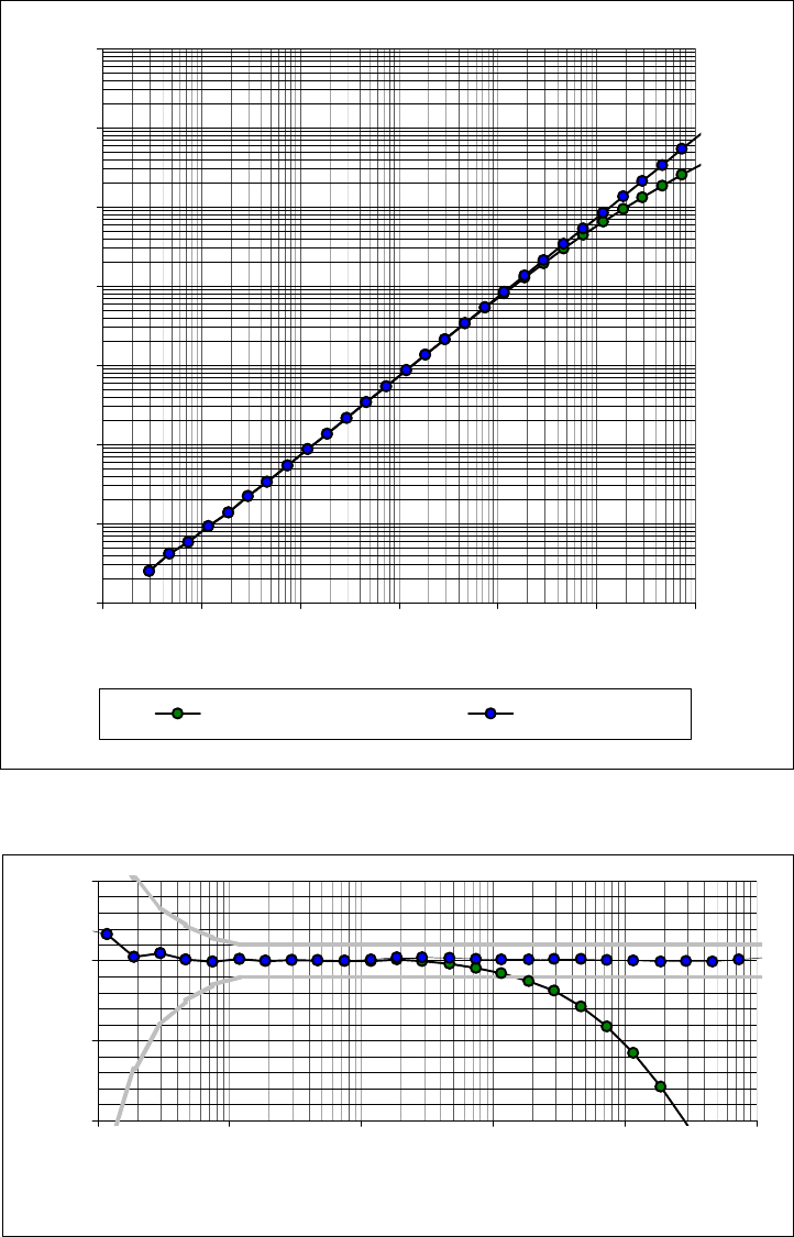
Conversion Factor Assessment
Head 900 MHz ε
r
=42 ± 5% σ =0.97 ± 10% mho/m
ConvF X 6.83 ± 7% (k=2) Boundary effect:
ConvF Y 6.83 ± 7% (k=2) Alpha 0.37
ConvF Z 6.83 ± 7% (k=2) Depth 2.48
Head 1800 MHz ε
r
=40 ± 5% σ =1.40 ± 10% mho/m
ConvF X 5.78 ± 7% (k=2) Boundary effect:
ConvF Y 5.78 ± 7% (k=2) Alpha 0.53
ConvF Z 5.78 ± 7% (k=2) Depth 2.01
ET3DV6 SN:1590
f = 900 MHz, WG R9 (head)
0.00
0.10
0.20
0.30
0.40
0.50
0.60
0.70
0.80
0.90
0 20 40 60
z[mm]
SAR[mW/cm3] / W
Analytical Measuremets
f = 1800 MHz, WG R22 (head)
0.00
1.00
2.00
3.00
4.00
5.00
6.00
7.00
0 20 40 60
z[mm]
SAR[mW/cm3] / W
Analytical Measuremets
Page 7 of 8

Deviation from Isotropy in HSL
Error (θ,φ ), f = 900 MHz
0
40
80
120
160
200
240
280
320
010 20 30 40 50 60
-1.00
-0.80
-0.60
-0.40
-0.20
0.00
0.20
0.40
0.60
0.80
1.00
Error [dB]
θ
φ
-1.00--0.80 -0.80--0.60 -0.60--0.40 -0.40--0.20 -0.20-0.00
0.00-0.20 0.20-0.40 0.40-0.60 0.60-0.80 0.80-1.00
Page 8 of 8
CELLTECH RESEARCH INC. Test Report S/N: 092601-169ARU
1955 Moss Court, Kelowna Date of Tests: October 16, 2001
B.C. Canada V1Y 9L3 FCC SAR Evaluation
_________________________________________________________________________________________________________
© 2001 Celltech Research Inc. RELM WIRELESS CORP. FCC ID: ARURPV516A 16
Portable VHF PTT Radio Transceiver (150-174MHz)
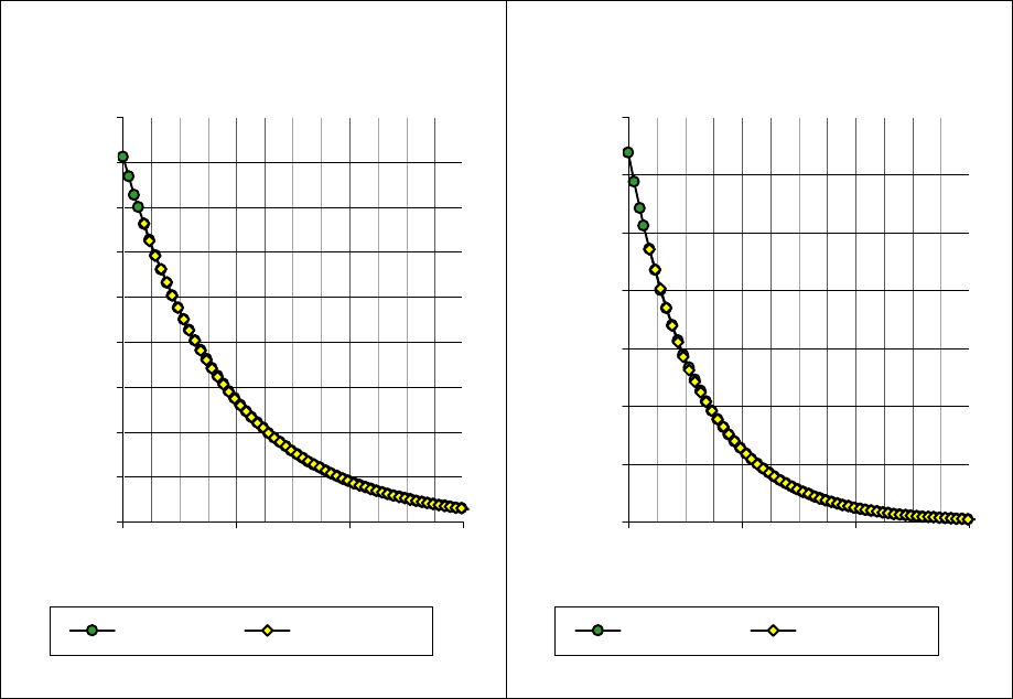
APPENDIX D - DETERMINATION OF E-FIELD PROBE CONVERSION NUMBERS

Determination of Probe Conversion Factors for 150MHz
Since at this time there exists no experimental method in determining E-field probe
conversion factors for frequencies below 800MHz, the following procedure was carried
out to give an approximation of the probe conversion factors for 150MHz.
The accuracy of the system was determined based on the two calibrated test frequencies
of 900 and 1800MHz, using validation dipoles as supplied by the manufacturer. The
measured results were found to be within the specified tolerances. For conversion factors
outside these two frequencies a linear extrapolation was performed as per the
manufacturer’s recommendations. In order to determine the accuracy of the conversion
factors, 300 and 450MHz dipoles were constructed in accordance with IEEE Std. P1528.
The two dipoles were then characterized for SAR using the appropriate head simulating
fluid for the given frequencies in a planar phantom as prescribed in IEEE Std. P1528.
The table below indicates the analytical target values for each dipole with the associated
measured results.
Frequency
(MHz)
Analytical SAR
@ 1W input
averaged over
1 gram
Measured SAR
@ 1W input
averaged over
1 gram
Delta
∆∆ Fluid Parameters
εr=45.3
300 3.0 3.51 17.0% σ=0.87
εr=43.5
450 4.9 5.77 17.8% σ=0.87
The extrapolated head conversion factors determined for 300 and 450MHz resulted in
SAR values being 17.0% and 17.8% greater than expected for each frequency
respectively. It is assumed that as this extrapolation is extended down to 150MHz, the
resulting SAR will again be overestimated by at least 17%.
The body conversion factors were determined based on a combination of the obtained
data from the validations, and numerical modeling results from an identical probe from
the same manufacturer.
The following two pages show examples of the conversion factors that were derived
through numerical modeling for a probe of similar properties.
Dosimetric E-Field Probe ET3DV6 E
E
EX
X
XA
A
AM
M
MP
P
PL
L
LE
E
E
Head Tissue Conversion Factor (+ standard deviation)
400 MHz ConvF 7.64 + 8%
835 MHz ConvF 6.54 + 8%
900 MHz ConvF 6.41 + 8%
350 MHz ConvF 7.76 + 8%
450 MHz ConvF 7.52 + 8%
835 MHz ConvF 6.53 + 8%
925 MHz ConvF 6.37 + 8%
1500 MHz ConvF 6.04 + 8%
1900 MHz ConvF 5.41 + 8%
2450 MHz ConvF 5.18 + 8%
2450 MHz ConvF 5.40 + 8%
ε
r = 44.4
σ = 0.87 mho/m
CENELEC Head Tissue
ε
r = 42.5
σ = 0.98 mho/m
CENELEC Head Tissue
ε
r = 42.3
σ = 0.99 mho/m
CENELEC Head Tissue
ε
r = 44.7
σ = 0.87 mho/m
IEEE Head Tissue
ε
r = 43.5
σ = 0.87 mho/m
IEEE Head Tissue
ε
r = 41.5
σ = 0.90 mho/m
IEEE Head Tissue
ε
r = 41.45
σ = 0.98 mho/m
IEEE Head Tissue
ε
r = 40.43
σ = 1.23 mho/m
IEEE Head Tissue
ε
r = 40.0
σ = 1.40 mho/m
IEEE Head Tissue
ε
r = 39.2
σ = 1.8 mho/m
IEEE Head Tissue
ε
r = 37.2
σ = 2.09 mho/m
H1800 at 2450 MHz

Dosimetric E-Field Probe ET3DV6 E
E
EX
X
XA
A
AM
M
MP
P
PL
L
LE
E
E
Body Tissue Conversion Factor (+ standard deviation)
35 MHz ConvF 8.77 + 15%
75 MHz ConvF 8.68 + 10%
150 MHz ConvF 8.51 + 8%
350 MHz ConvF 7.64 + 8%
450 MHz ConvF 7.40 + 8%
784 MHz ConvF 6.38 + 8%
835 MHz ConvF 6.28 + 8%
925 MHz ConvF 6.10 + 8%
1500 MHz ConvF 5.44 + 8%
1900 MHz ConvF 4.82 + 8%
2450 MHz ConvF 4.53 + 8%
ε
r = 85.19
σ = 0.69 mho/m
FCC Body Tissue
ε
r = 69.93
σ = 0.72 mho/m
FCC Body Tissue
ε
r = 62.68
σ = 0.75 mho/m
FCC Body Tissue
ε
r = 58.41
σ = 0.80 mho/m
FCC Body Tissue
ε
r = 57.62
σ = 0.83 mho/m
FCC Body Tissue
ε
r = 56.25
σ = 0.93 mho/m
FCC Body Tissue
ε
r = 56.11
σ = 0.95 mho/m
FCC Body Tissue
ε
r = 55.9
σ = 0.98 mho/m
FCC Body Tissue
ε
r = 54.87
σ = 1.23 mho/m
FCC Body Tissue
ε
r = 54.3
σ = 1.45 mho/m
FCC Body Tissue
ε
r = 53.57
σ = 1.81 mho/m
FCC Body Tissue
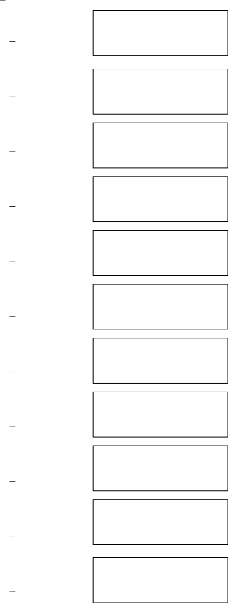
Body Conversion Factor a given Frequency
0
1
2
3
4
5
6
7
8
9
10
0500 1000 1500 2000 2500 3000
Frequency (MHz)
Conversion Factor
Head and Body Conversion Factors
0
1
2
3
4
5
6
7
8
0 500 1000 1500 2000 2500 3000
Frequency (MHz)
Conversion Factor
Head CF
Body CF

Frequency Head Conversion
Factors
Body Conversion
Factors
Delta
∆∆
450 7.52 7.40 1.62
835 6.53 6.28 3.98
925 6.37 6.10 4.43
1500 6.04 5.44 11.02
1900 5.41 4.82 12.24
2450 5.18 4.53 14.35
Conclusion:
Based on the results from the 300 and 450MHz validations, the derived conversion
factors should over-estimate the SAR for a device operating in the 150MHz band by
approximately 17%. In addition, the above graphs and tabular results show that the probe
conversion factors vary only slightly between head and body as the frequency approaches
450MHz. It is therefore safe to assume that as the frequency is further extended to
150MHz, the difference in the conversion factors between head and body will be less
significant. Therefore, for this reason only one conversion factor is reported for both
head and body at 150MHz.
CELLTECH RESEARCH INC. Test Report S/N: 092601-169ARU
1955 Moss Court, Kelowna Date of Tests: October 16, 2001
B.C. Canada V1Y 9L3 FCC SAR Evaluation
_________________________________________________________________________________________________________
© 2001 Celltech Research Inc. RELM WIRELESS CORP. FCC ID: ARURPV516A 17
Portable VHF PTT Radio Transceiver (150-174MHz)
APPENDIX E - SAR SENSITIVITIES
Application Note: SAR Sensitivities
Schmid & Partner Engineering AG, Zurich, Switzerland
Application Note: SAR Sensitivities
Introduction
The measured SAR-values in homogeneous phantoms depend strongly on the electrical
parameters of the liquid. Liquids with exactly matching parameters are difficult to produce;
there is always a small error involved in the production or measurement of the liquid
parameters. The following sensitivities allow the estimation of the influence of small
parameter errors on the measured SAR values. The calculations are based on an
approximation formula [1] for the SAR of an electrical dipole near the phantom surface and
a adapted plane wave approximation for the penetration depth. The sensitivities are given in
percent SAR change per percent change in the controlling parameter:
d SAR / SAR
S(x) = ———————
d x / x
The controlling parameters x are:
• ε: permitivity
• σ: conductivity
• ρ: brain density (= one over integration volume)
For example: If The liquid permitivity increases by 2 percent and the sensitivity of the SAR
to permitivity is -0.6 then the SAR will decrease by 1.2 percent.
The sensitivities are given for surface SAR values and averaged SAR values for 1 g and 10
g cubes and for dipole distances d of 10mm (for frequencies below 1000 MHz) and 15mm
(for frequencies above 1000 MHz) from the liquid surface.
Liquid parameters are as proposed in the new standards (e.g., IEEE 1528).
References
[1] N. Kuster and Q. Balzano, “Energy absorption mechanism by biological bodies in the
near field of dipole antennas above 300 MHz”, IEEE Transacions on Vehicular
Technology, vol. 41(1), pp. 17-23, 1992.

Application Note: SAR Sensitivities
Schmid & Partner Engineering AG, Zurich, Switzerland
Parameter εσ ρ
f=300 MHz (εr=45.3, σ=0.87S/m, ρ=1g/cm3)
d=15mm: Surface - 0.41 + 0.48 —
1 g - 0.33 + 0.28 0.08
10 g - 0.26 + 0.09 0.16
f=450 MHz (εr=43.5, σ=0.87S/m, ρ=1g/cm3)
d=15mm: Surface - 0.56 + 0.67 —
1 g - 0.46 + 0.43 0.09
10 g - 0.37 + 0.22 0.17
f=835 MHz (εr=41.5, σ=0.90S/m, ρ=1g/cm3)
d=15mm: Surface - 0.70 + 0.86 —
1 g - 0.57 + 0.59 0.10
10 g - 0.45 + 0.35 0.18
f=900 MHz (εr=41.5, σ=0.97S/m, ρ=1g/cm3)
d=15mm: Surface - 0.69 + 0.86 —
1 g - 0.55 + 0.57 0.10
10 g - 0.44 + 0.32 0.19
f=1450 MHz (εr=40.5, σ=1.20/m, ρ=1g/cm3)
d=10mm: Surface - 0.73 + 0.91 —
1 g - 0.55 + 0.55 0.12
10 g - 0.42 + 0.27 0.22
f=1800 MHz (εr=40.0, σ=1.40S/m, ρ=1g/cm3)
d=10mm: Surface - 0.73 + 0.92 —
1 g - 0.52 + 0.51 0.14
10 g - 0.38 + 0.21 0.24
f=1900 MHz (εr=40.0, σ=1.40S/m, ρ=1g/cm3)
d=10mm: Surface - 0.73 + 0.93 —
1 g - 0.53 + 0.51 0.14
10 g - 0.39 + 0.22 0.24
f=2000 MHz (εr=40.0, σ=1.40S/m, ρ=1g/cm3)
d=10mm: Surface - 0.74 + 0.94 —
1 g - 0.53 + 0.52 0.14
10 g - 0.39 + 0.22 0.24
f=2450 MHz (εr=39.2, σ=1.80S/m, ρ=1g/cm3)
d=10mm: Surface - 0.74 + 0.93 —
1 g - 0.49 + 0.41 0.17
10 g - 0.34 + 0.12 0.28
f=3000 MHz (εr=38.5, σ=2.40S/m, ρ=1g/cm3)
d=10mm: Surface - 0.75 + 0.90 —
1 g - 0.45 + 0.28 0.21
10 g - 0.32 + 0.02 0.31
CELLTECH RESEARCH INC. Test Report S/N: 092601-169ARU
1955 Moss Court, Kelowna Date of Tests: October 16, 2001
B.C. Canada V1Y 9L3 FCC SAR Evaluation
_________________________________________________________________________________________________________
© 2001 Celltech Research Inc. RELM WIRELESS CORP. FCC ID: ARURPV516A 18
Portable VHF PTT Radio Transceiver (150-174MHz)
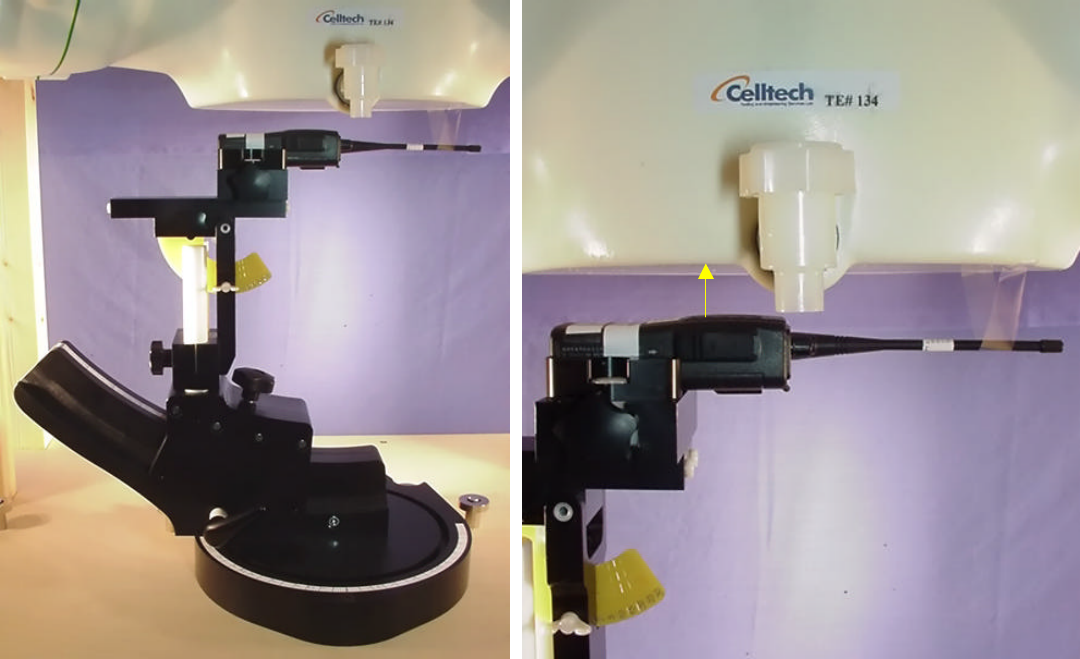
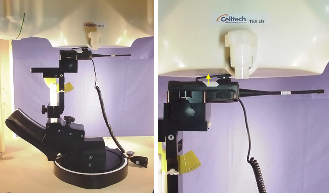
APPENDIX F - SAR TEST SETUP PHOTOGRAPHS
CELLTECH RESEARCH INC. Test Report S/N: 092601-169ARU
1955 Moss Court, Kelowna Date of Tests: October 16, 2001
B.C. Canada V1Y 9L3 FCC SAR Evaluation
_________________________________________________________________________________________________________
© 2001 Celltech Research Inc. RELM WIRELESS CORP. FCC ID: ARURPV516A
Portable VHF PTT Radio Transceiver (150-174MHz)
FACE-HELD SAR TEST SETUP PHOTOGRAPHS
2.5cm Separation Distance
2.5 cm
CELLTECH RESEARCH INC. Test Report S/N: 092601-169ARU
1955 Moss Court, Kelowna Date of Tests: October 16, 2001
B.C. Canada V1Y 9L3 FCC SAR Evaluation
_________________________________________________________________________________________________________
© 2001 Celltech Research Inc. RELM WIRELESS CORP. FCC ID: ARURPV516A
Portable VHF PTT Radio Transceiver (150-174MHz)
BODY-WORN SAR TEST SETUP PHOTOGRAPHS
with 1.4cm Belt-Clip
1.4 cm