Realtek Semiconductor RTL8191SE 802.11b/g/n RTL8191SE miniCard User Manual
Realtek Semiconductor Corp. 802.11b/g/n RTL8191SE miniCard
UserManual.wiki
>
Realtek Semiconductor
>
RTL8191SE User Manual
>
User manual
Contents
1.
User Manual
2.
USERS MANUAL
3.
Users Manual
4.
(RTL8191SE) UserMan 0303
5.
User Manual 1
6.
User Manual 2
7.
User manual
User manual
Navigation menu
Upload a User Manual
Namespaces
Wiki Guide
HTML
PDF
Info
Views
User Manual
Discussion / Help
Navigation
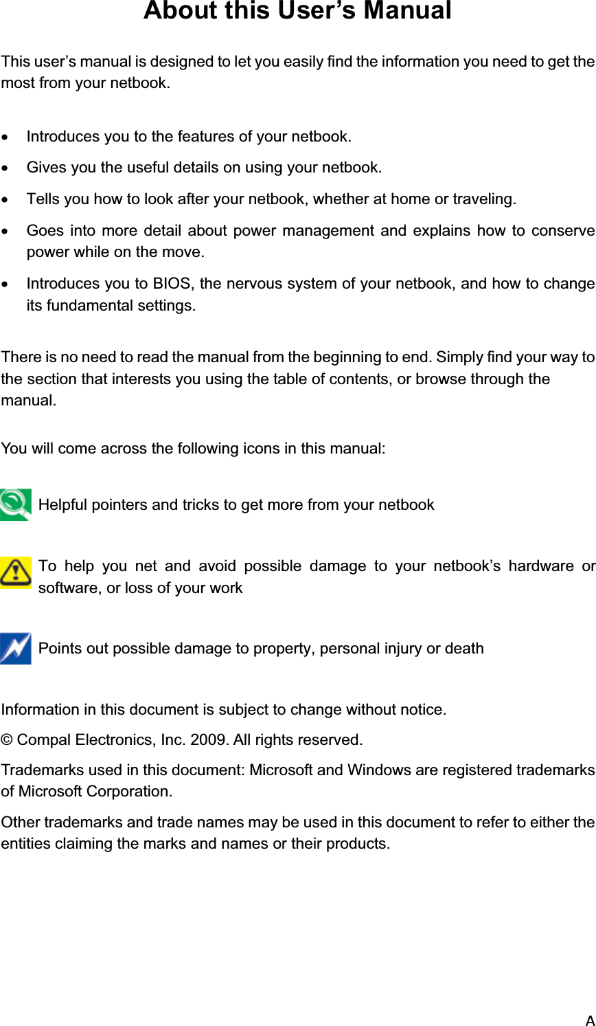
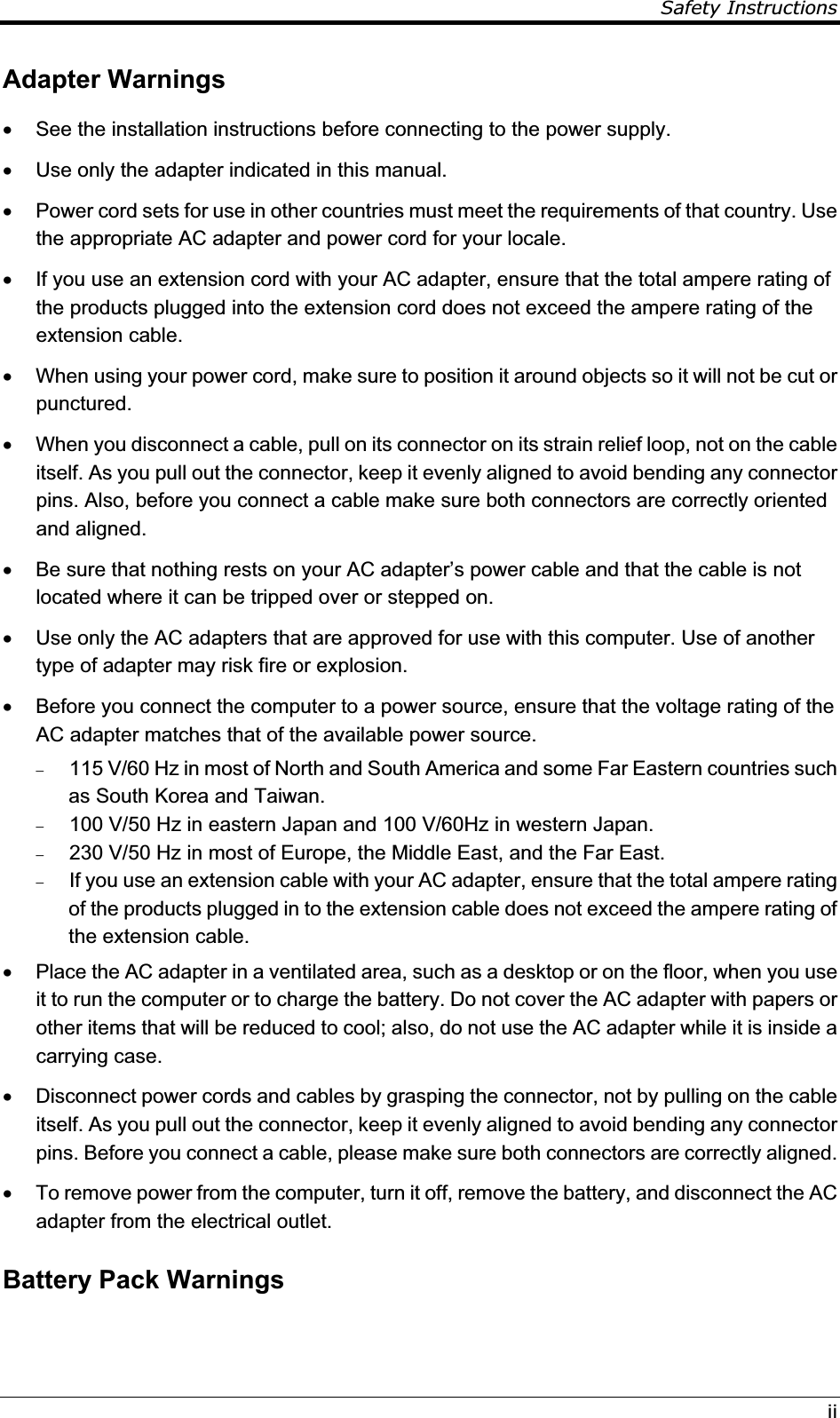


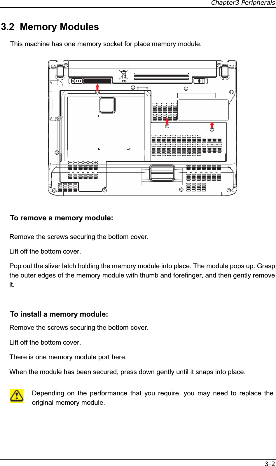
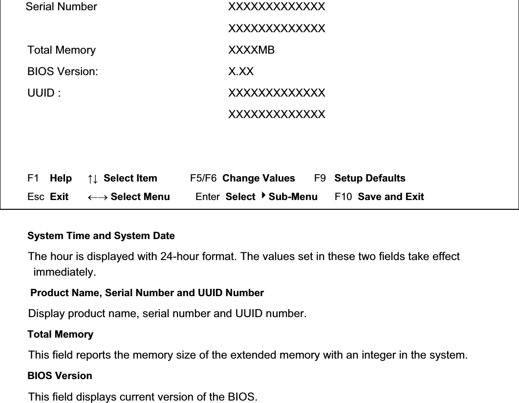
![6¾ 4.1 System Controls 4.1 System Setup 4.1.1 Invoking setup The setup function can only be invoked by pressing F2 when “Press <F2> to enter Setup” message is prompted on the bottom of screen during POST. During setup, all Fn function keys and power saving functions are disabled. 4.1.2Setup screens 4.1.2.1 Main Menu InsydeH20 Setup Utility Rev. 3.5 Main Advanced Security Boot Exit System Time [12:00:00] System Date [01/01/2008] Product Name: XXXXXXX This is the help for the Hour field. Valid range is from 0 to 23. INCREASE/REDUCE : +/-](https://usermanual.wiki/Realtek-Semiconductor/RTL8191SE.User-manual/User-Guide-1423009-Page-42.png)
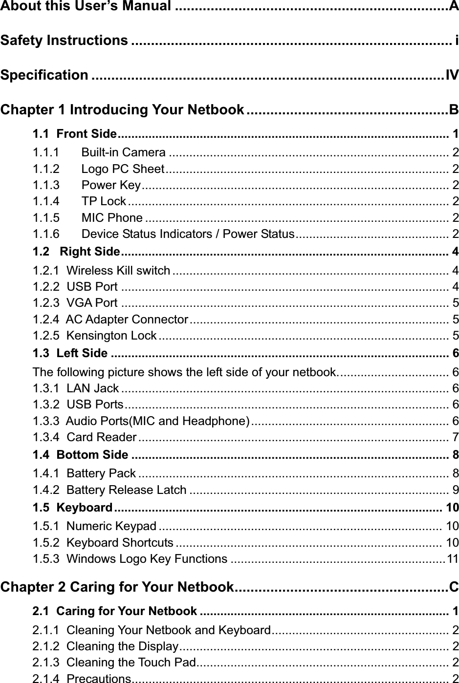
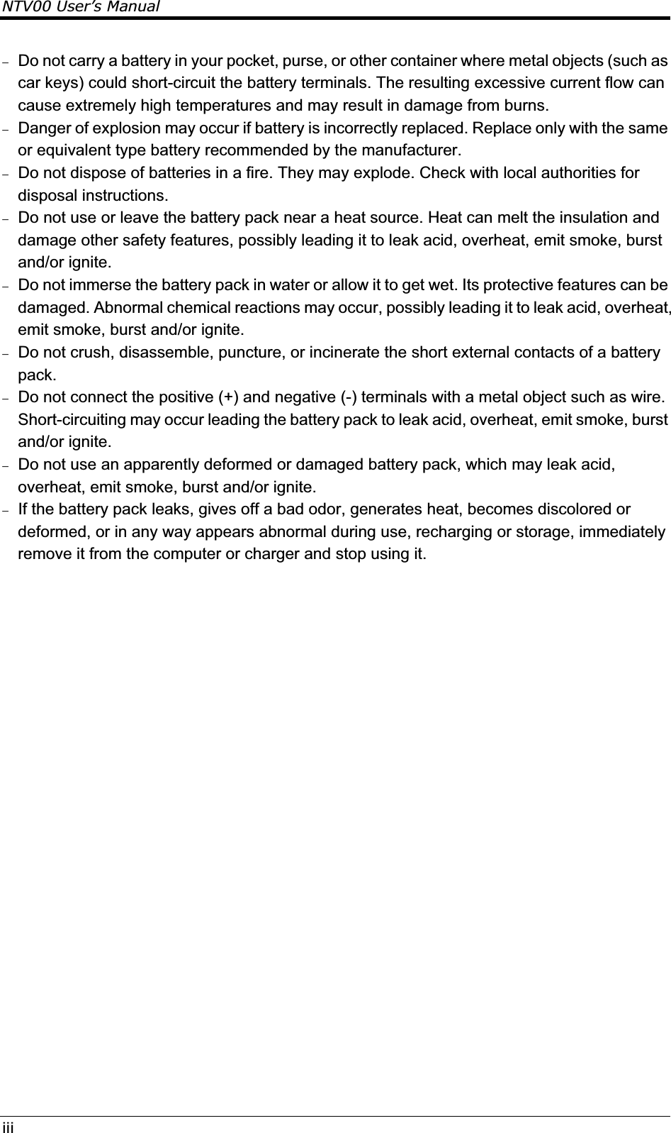
![84.1.2.2 Advanced Menu InsydeH20 Setup Utility Rev. 3.5 Main Advanced Security Boot Exit AHCI Mode < Enabled/Disabled > F1 Help ĹĻ Select Item F5/F6 Change Values F9 Setup Defaults Esc Exit mo Select Menu Enter Select Sub-Menu F10 Save and Exit AHCI Mode Allows the user to set AHCI Enable or Disable. AHCI Mode [ Enabled ] [ Disabled ]](https://usermanual.wiki/Realtek-Semiconductor/RTL8191SE.User-manual/User-Guide-1423009-Page-44.png)
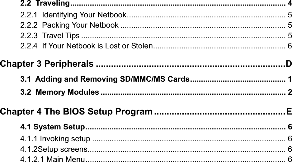
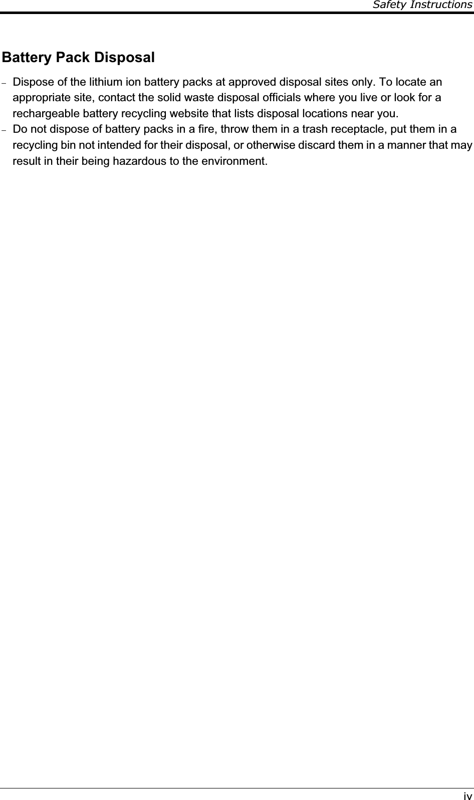
![94.1.2.3 Security Menu InsydeH20 Setup Utility Rev. 3.5 Main Advanced Security Boot Exit Supervisor Password : Not Installed Set Supervisor Password Install or Change the password and the length of password must be greater than one word F1 Help ĹĻ Select Item F5/F6 Change Values F9 Setup Defaults Esc Exit mo Select Menu Enter Select Sub-Menu F10 Save and Exit Set Supervisor Password Install or Change the password and the length of password must be greater than one word. Set Supervisor Password Please type in your new password [ ] Please confirm your new password [ ] Power on Password If have set Supervisor Password, then allows the user to set power on password enable or disable. Power on password [ Enabled ] [ Disabled ] Enable: System will ask input password on post time.](https://usermanual.wiki/Realtek-Semiconductor/RTL8191SE.User-manual/User-Guide-1423009-Page-45.png)
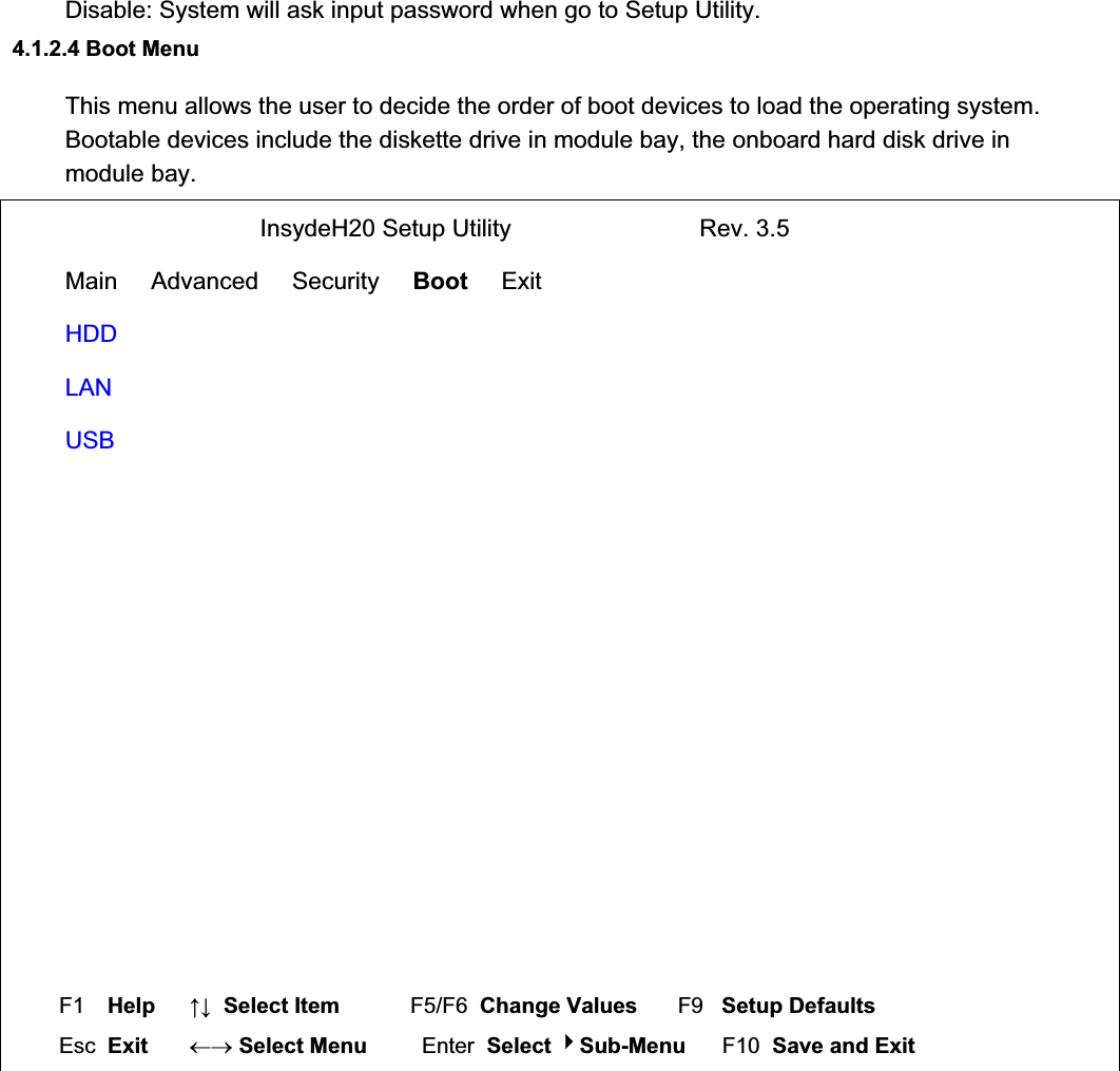
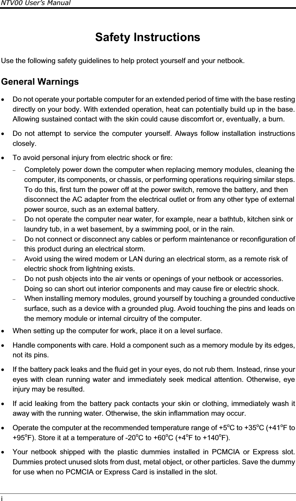
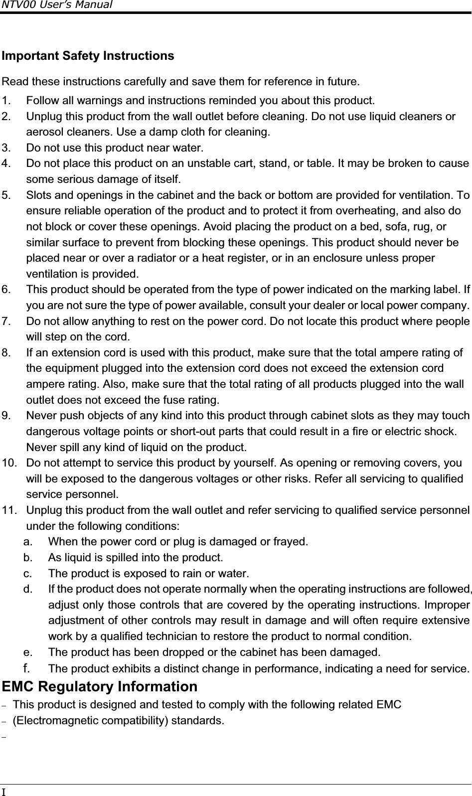
![114.1.2.5 Exit Menu InsydeH20 Setup Utility Rev. 3.5 Main Advanced Security Boot Exit Exit Saving ChangesExit Discarding ChangesLoad Optimal Defaults Exit system setup and save your changes. F1 Help ĹĻ Select Item F5/F6 Change Values F9 Setup Defaults Esc Exit mo Select Menu Enter Select Sub-Menu F10 Save and Exit Exit Saving Changes Allows the user to save changes to CMOS and reboot system. The following message is prompted when user press “Enter” on the item. Exit Saving Changes? [Yes] [No] Yes: Exit SETUP and reboot No: Back to previous screen Exit Discarding Changes Exit Discarding Changes? [Yes] [No]](https://usermanual.wiki/Realtek-Semiconductor/RTL8191SE.User-manual/User-Guide-1423009-Page-47.png)
![Chapter4 The BIOS Setup Program4-12Load Optimal Defaults Allows the user loads default value in CMOS Setup. The following message is prompted when user press “Enter” on this item: Load Optimal Defaults? [Yes] [No]](https://usermanual.wiki/Realtek-Semiconductor/RTL8191SE.User-manual/User-Guide-1423009-Page-48.png)