Recognition Source DCMI2001 Access control panel interface module User Manual 381127
Recognition Source, LLC Access control panel interface module 381127
Contents
Antenna manual

P
P
PR
R
RE
E
EL
L
LI
I
IM
M
MI
I
IN
N
NA
A
AR
R
RY
Y
Y
INSTALLATION INSTRUCTIONS
OPTIONAL
REMOTE ANTENNA
MODULES
(RAM)
Includes Installation Instructions for:
ANT-REMOTE & ANT-6DB-FLAT
3820 Stern Avenue
St. Charles, IL 60174
Phone: 630-762-4450
Fax: 630-762-4455
P/N: M053-xxx-x001

3820 Stern Avenue
St. Charles, IL 60174
(630) 762-4450
P/N: M053-xxx-x001 (630) 762-4444 fax Page 2 of 29
INSTALLATION INSTRUCTIONS
Optional Remote Antenna Modules (RAM’s)
NOTE: These instructions are for installing an optional Remote Antenna Module (RAM), an accessory of a
Wyreless Access System.
Table of Contents
1. Wyreless AccessTM System Components............................................................................................................3
1.1 Overview .......................................................................................................................................................3
1.2 Optional Remote Antenna Module (RAM) Components ..............................................................................4
2. Safety, Grounding, & Lightning Considerations ..............................................................................................7
2.1 Safety.............................................................................................................................................................7
2.2 Antenna Grounding .......................................................................................................................................7
2.3 Lightning Protection Consideration...............................................................................................................7
3. Installing the ANT-REMOTE ............................................................................................................................8
3.1 Tools Required ..............................................................................................................................................8
3.2 Determining the Best ANT-REMOTE Location ...........................................................................................8
3.3 Mounting the ANT-REMOTE.......................................................................................................................9
3.4 Connecting the ANT-REMOTE Coax...........................................................................................................9
4. Installing the ANT-6DB-FLAT.........................................................................................................................10
4.1 Tools Required ............................................................................................................................................10
4.2 Determining the Best ANT-6DB-FLAT Location.......................................................................................10
4.3 Mounting the ANT-6DB-FLAT ..................................................................................................................12
4.4 Connecting the ANT-6DB-FLAT Coax ......................................................................................................14
5. Connecting the Coax..........................................................................................................................................15
5.1 Grounding & Lightning Protection Consideration.......................................................................................15
5.2 Routing the Coax.........................................................................................................................................15
5.3 Dressing the Coax........................................................................................................................................17
5.4 Terminating the Coax at the RAM...............................................................................................................17
5.5 Terminating the Coax at the PIM or WRI ...................................................................................................17
5.6 Connecting Coax to a PIM or PIME............................................................................................................17
5.7 Connecting Coax to a WRI..........................................................................................................................22
6. FCC Compliance & Warnings..........................................................................................................................27
6.1 FCC Compliance .........................................................................................................................................27
6.2 Warnings......................................................................................................................................................27
7. Contacting Recognition Source ........................................................................................................................28
8. Revision History.................................................................................................................................................29
3820 Stern Avenue
St. Charles, IL 60174
(630) 762-4450
P/N: M053-xxx-x001 (630) 762-4444 fax Page 3 of 29
1. Wyreless AccessTM System Components
1.1 Overview
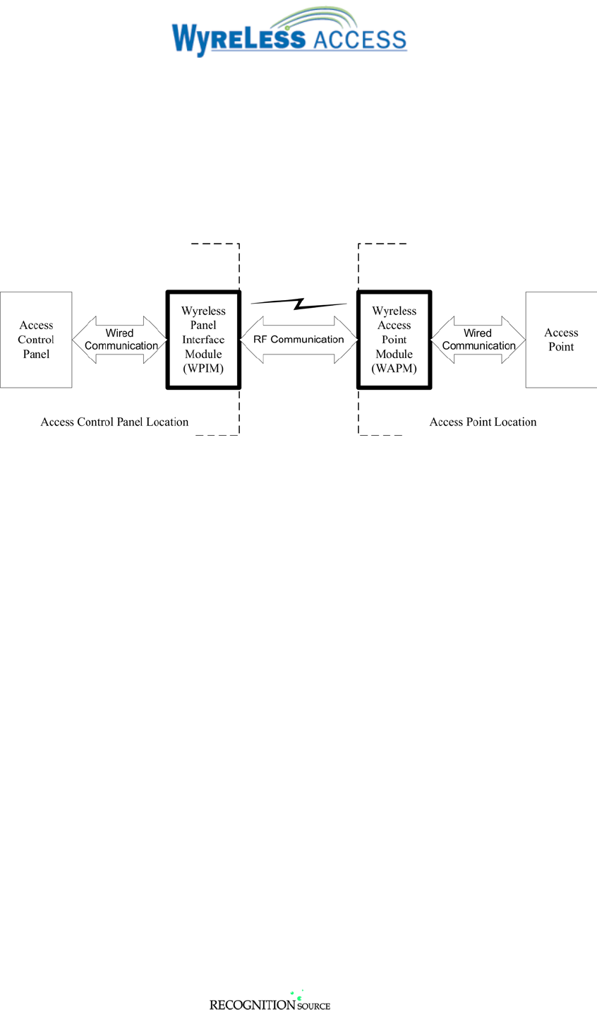
Every access control system that uses Wyreless AccessTM contains two different types of modules (Figure
1-1):
• at least one Wyreless Panel Interface Module (WPIM), and
• at least one Wyreless Access Point Module (WAPM)
Figure 1-1 – Wyreless Access System Block Diagram
Recognition Source’s product line contains several different expressions of each module.
The WPIM is wired to the access control panel and ideally is installed very close to the access control
panel. The WPIMs installation location is determined by the location of the WAPMs with which it will
communicate using RF.
The WAPM is installed at the access point where access will be controlled and/or monitored. Depending
on the application and which WAPM is used, some wiring at the access control point may be required.
Regardless of which WPIM or WAPM module is used, the communication link between the WPIM and
WAPM is always RF.
This manual describes the installation of three different optional Remote Antenna Modules which can be
an accessory of either a WPIM or a WAPM.
3820 Stern Avenue
St. Charles, IL 60174
(630) 762-4450
P/N: M053-xxx-x001 (630) 762-4444 fax Page 4 of 29
1.2 Optional Remote Antenna Module (RAM) Components & Accessories
All Wireless Panel Interface Modules (WPIMs) and all Wireless Access Point Modules (WAPMs)
contain either an internal or attached antenna.
There are two major reasons why an optional antenna might be used:
• To remote the antenna from the Wyreless Access Module location so that the Wyreless Access
Module can be located in more serviceable and/or secure area.
• To increase the RF range by using a directional antenna that provides RF gain.
Several Wyreless Access Modules have the option of using an optional antenna, see Table 1-3.
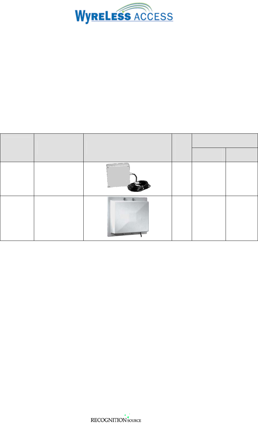
Recognition Source offers three different optional antennae (Table 1-1). Any optional antenna can be
used on any Wyreless Access Module that will accept an optional antenna.
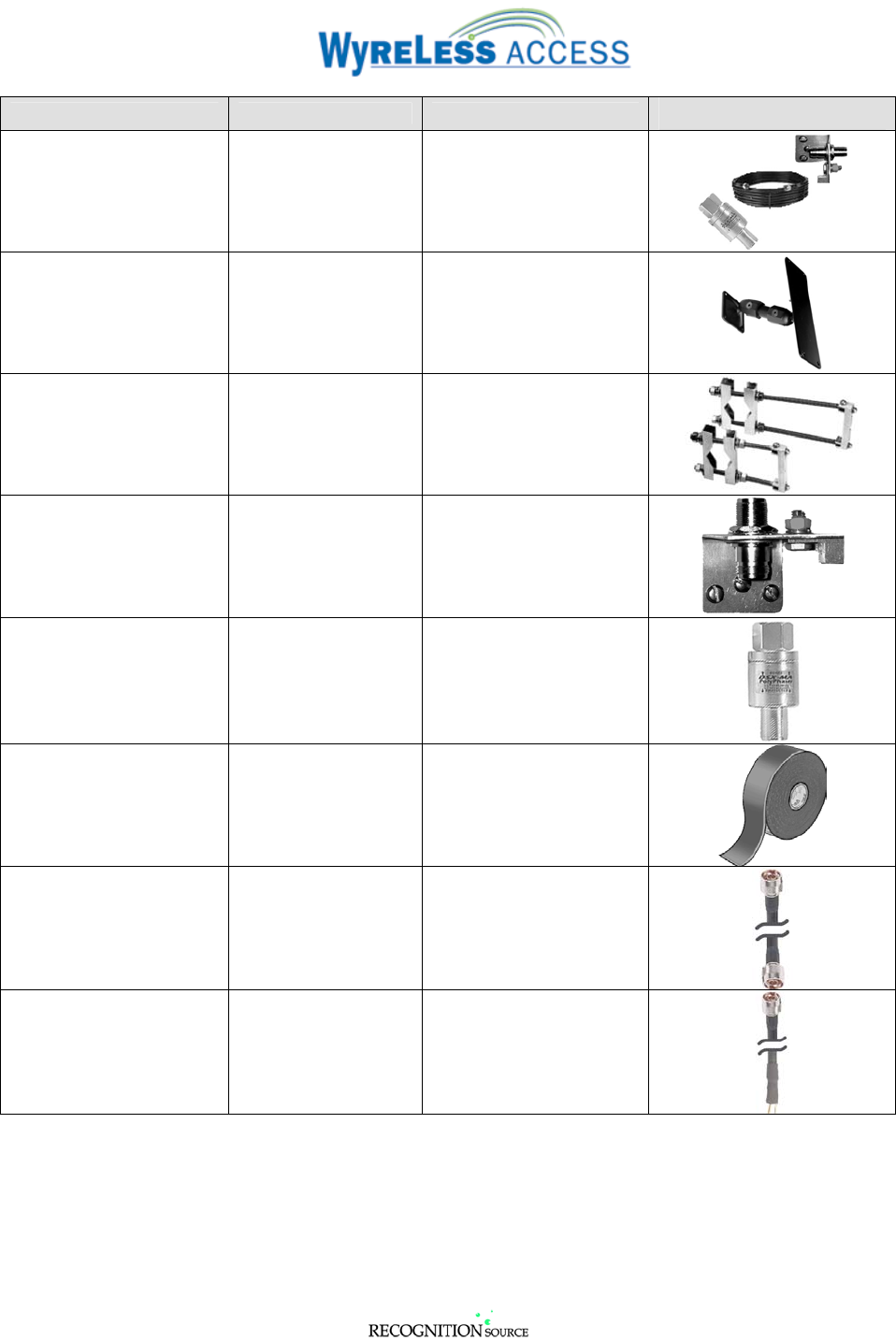
Various antenna accessories are also available (Table 1-2).
Beamwidth @ ½ Power
Antenna
Type Model Number Picture
RF
Gain
(dB) Horizontal Vertical
Remote ANT-Remote
0 360o 360o
Directional
Panel ANT-6DB-FLAT
6 90o 60o
Table 1-1 – Optional Antennae
3820 Stern Avenue
St. Charles, IL 60174
(630) 762-4450
P/N: M053-xxx-x001 (630) 762-4444 fax Page 5 of 29
Accessory Supplier Model Number Picture
Lightning Protection Kit Recognition Source ANT-LPK
Adjustable Articulating
Mounting Bracket for
ANT-6DB-FLAT
Recognition Source
or
Maxrad
ANT-FLAT-BRACKET
or
MPAB3
Adjustable Mast Mounting
Bracket for ANT-6DB-
FLAT
Maxrad MPAB4
Grounding Block Maxrad MGB
Surge Protection Filter PolyPhaser DSXL-MA
Weatherseal Tape McMaster-Carr 76385A15
5’, 50 ohm, low loss coax,
type N male connectors on
both ends
Maxrad MCA195NMNM/5ft
15’, 50 ohm, low loss
cable, type N male
connector on one end,
dressed bare wires on the
other end
Recognition Source A771-008-001
Table 1-2 - Remote Antenna Accessories

3820 Stern Avenue
St. Charles, IL 60174
(630) 762-4450
P/N: M053-xxx-x001 (630) 762-4444 fax Page 6 of 29
Standard Optional
Wyreless
Access
Product
Internal
or
Attached
Antenna
ANT-
REMOTE
ANT-
6DB-FLAT
PIM-OTD √ √ √
PIME-OTD √ √ √
PIM-OTD-485 √ √ √
WRI-100-OTD √ √ √
MIRL √
WPR √
WISI √
WUSI √
WCM √
Table 1-3 – Wyreless Access Products Antenna Options
3820 Stern Avenue
St. Charles, IL 60174
(630) 762-4450
P/N: M053-xxx-x001 (630) 762-4444 fax Page 7 of 29
2. Safety, Grounding, & Lightning Considerations
WARNING: Make certain that the Coax installation conforms to all
electrical codes (national and local) regarding grounding and lightning
protection requirements.
PolyPhaser’s Technical Information section of their web site
(www.polyphaser.com ) contains excellent information about grounding
and lightning protection.
2.1 Safety
An outside antenna system should not be located in the vicinity of overhead power lines or other electric
light or power circuits, or where it can fall into such power lines or circuits. When installing an outside
antenna system, extreme care should be taken to keep from touching such power lines or circuits as
contact with them might be fatal
2.2 Antenna Grounding
The National Electrical Code (NEC) requires that every antenna installation be grounded. Also many
areas have local antenna-grounding codes. Be sure that you are familiar with all of the grounding and
other antenna regulations in your area.
Antenna grounding includes mast grounding and coax grounding.
Make sure the antenna is grounded so as to provide some protection against voltage surges and built up
static charges. Section 810 of the National Electrical Code, ANSI/NFPA No.70-1984, provides
information with respect to proper grounding of the mast and supporting structure, grounding of the lead-
in wire to an antenna discharge unit, size of grounding conductors, location of antenna discharge unit,
connection to grounding electrodes, and requirements for the grounding electrode.
A grounding block compatible with all Recognition Source Remote Antennae is available as an
accessory, see Table 1-2, on page 5 above.
PolyPhaser’s Technical Information section of their web site (www.polyphaser.com ) contains excellent
information about grounding.
2.3 Lightning Protection Consideration
Where lightning protection is a concern, a lightning protection device must be installed in series with the
coax and mounted at the antenna end of the coax cable.
A lightning protection device (surge protection filter) compatible with all Recognition Source Remote
Antennae is available as an accessory, see Table 1-2, on page 5 above.
Install one of these devices at the antenna per PolyPhaser’s instructions including weatherization
requirements.
PolyPhaser’s Technical Information section of their web site (www.polyphaser.com ) contains excellent
information about lightning protection.

3820 Stern Avenue
St. Charles, IL 60174
(630) 762-4450
P/N: M053-xxx-x001 (630) 762-4444 fax Page 8 of 29
3. Installing the ANT-REMOTE
WARNING: You can be seriously or fatally injured if this antenna comes in contact with electric power
lines or is brought in proximity with a high voltage electrical field. For your own safety, use extreme
caution when installing this antenna. Keep away from power lines!
The ANT-REMOTE can be used with on all “OTD” versions of a Panel Interface Module (PIM-OTD,
PIME-OTD, or PIM-OTD-485) or Wireless Reader Interface (WRI-100-OTD) (Table 1-3).
NOTE: The ANT-REMOTE can only be installed on a PIM-OTD, PIME-OTD, PIM-OTD-485, or
WRI-100-OTD.
3.1 Tools Required
• Hammer
• 9/32” drill bit & drill
• Flat and Phillips head screwdrivers (1/8” wide flat blade for screw terminals)
• Pencil
• ANT-REMOTE Mounting Kit (K381-000-001), provided, including four zinc, pan head
Phillips, 8-18 X 1 ½” sheet metal screws, four #8 flat washers, and four heavy-duty anchors
3.2 Determining the Best ANT-REMOTE Location
• The ANT-REMOTE must be mounted within 15 cable feet of the PIM or WRI.
• If the ANT-REMOTE is used with a PIM-OTD, PIME-OTD, or PIM-OTD-485, then the ANT-
REMOTE should be located so that it has the best “line of sight” path with all the WAPM’s that will
be linked to the PIM.
• If the ANT-REMOTE is used with a WRI-100-OTD, the ANT-REMOTE should be located so that it
has the best “line of sight” path with the WPIM to which it will be linked.

3820 Stern Avenue
St. Charles, IL 60174
(630) 762-4450
P/N: M053-xxx-x001 (630) 762-4444 fax Page 9 of 29
3.3 Mounting the ANT-REMOTE
3.3.1 Remove the ANT-REMOTE enclosure cover (Figure 3-1).
Figure 3-1 – ANT-REMOTE with Cover Removed
3.3.2 Place the ANT-REMOTE (cover removed) against the surface where it is to be mounted.
3.3.3 Using ANT-REMOTE enclosure as a template, mark the four corner mounting holes.
3.3.4 Drill a 9/32” hole in the surface at each mounting mark, 1 ¾” deep.
3.3.5 Insert the four anchors provided firmly into the holes so they are flush with the surface.
3.3.6 Fasten the ANT-REMOTE enclosure to the mounting surface using the screws & washers provided.
3.3.7 Replace the ANT-REMOTE enclosure cover.
3.4 Connecting the ANT-REMOTE Coax
For instructions on how to connect the ANT-REMOTE Coax to the PIM or WRI, proceed to section 5,
page 15.

3820 Stern Avenue
St. Charles, IL 60174
(630) 762-4450
P/N: M053-xxx-x001 (630) 762-4444 fax Page 10 of 29
4. Installing the ANT-6DB-FLAT
WARNING: You can be seriously or fatally injured if this antenna comes in contact with electric power
lines or is brought in proximity with a high voltage electrical field. For your own safety, use extreme
caution when installing this antenna. Keep away from power lines!
The ANT-6DB-FLAT can be used with on all “OTD” versions of a Panel Interface Module (PIM-OTD,
PIME-OTD, or PIM-OTD-485) or Wireless Reader Interface (WRI-100-OTD) (Table 1-3).
NOTE: The ANT-6DB-FLAT can only be installed on a PIM-OTD, PIME-OTD, PIM-OTD-485, or
WRI-100-OTD.
4.1 Tools Required
• Hammer
• 9/32” drill bit & drill
• Flat and Phillips head screwdrivers (1/8” wide flat blade for screw terminals)
• Pencil
• 7/16” wrench: adjustable, box, or open end
• RAM Mounting Kit (K381-000-001), provided, including four zinc, pan head Phillips, 8-18 X
1 ½” sheet metal screws, four #8 flat washers, and four heavy-duty anchors
4.2 Determining the Best ANT-6DB-FLAT Location
• The ANT-6DB-FLAT must be mounted within 15 cable feet of the PIM or WRI.
• If the ANT-6DB-FLAT is used with a PIM-OTD, PIME-OTD, or PIM-OTD-485, then
ANT-6DB-FLAT should be located so that it has the best “line of sight” path with all the WAPM’s
that will be linked to the PIM.
• If the ANT-6DB-FLAT is used with a WRI-100-OTD, the ANT-6DB-FLAT should be located so that
it has the best “line of sight” path with the WPIM to which it will be linked.
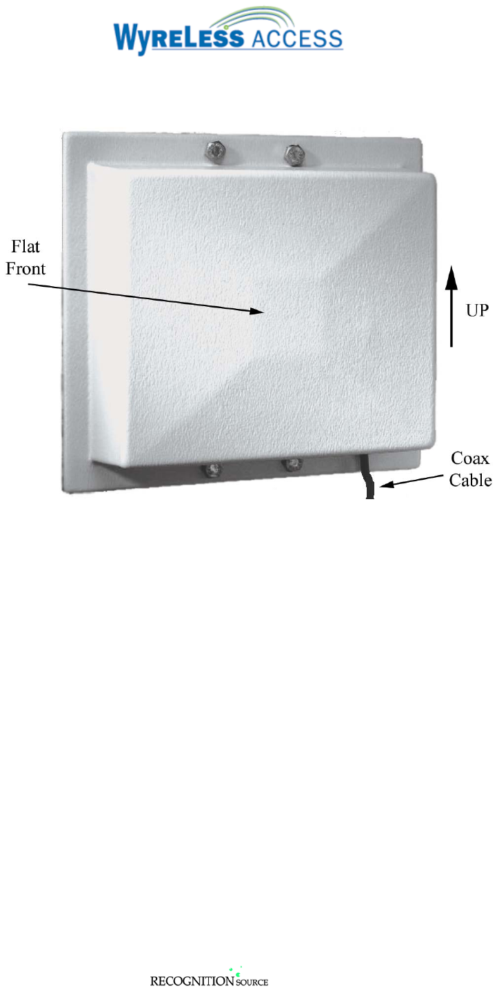
• Since the ANT-6DB-FLAT is a directional antenna, the mounting location and orientation is very
important:
3820 Stern Avenue
St. Charles, IL 60174
(630) 762-4450
P/N: M053-xxx-x001 (630) 762-4444 fax Page 11 of 29
⇒ The ANT-6DB-FLAT should be mounted and oriented so that the Flat Front is perpendicular to
the target antenna and that the Coax Cable exits at the bottom (a vertical polarization arrow is on
the back). (Figure 4-1 & Figure 4-2).
Figure 4-1 – ANT-6DB-FLAT Mounting Orientation
3820 Stern Avenue
St. Charles, IL 60174
(630) 762-4450
P/N: M053-xxx-x001 (630) 762-4444 fax Page 12 of 29
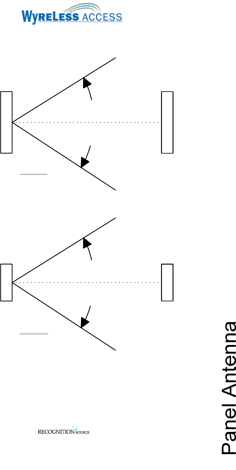
⇒ For optimum performance the ANT-6DB-FLAT should be oriented so that it’s vertical and
horizontal centerlines intersect the target antenna (Figure 4-2). The ANT-6DB-FLAT has 3 dB
horizontal beamwidth of 72 o and 3 dB vertical beamwidth of 57o.
•
Figure 4-2 - ANT-6DB-FLAT RF Radiation Pattern
4.3 Mounting the ANT-6DB-FLAT
The ANT-6DB-FLAT comes with two mounting kits: a clamp set for mounting to masts up to 1-1/2” in
diameter and a screw and anchor kit for flat surface mounting.
Two other mounting options, an articulating mounting kit and an adjustable mast mounting kit are
available as accessories, see Table 1-2, on page 5 above..
3820 Stern Avenue
St. Charles, IL 60174
(630) 762-4450
P/N: M053-xxx-x001 (630) 762-4444 fax Page 13 of 29
4.3.1 Mast Mounting
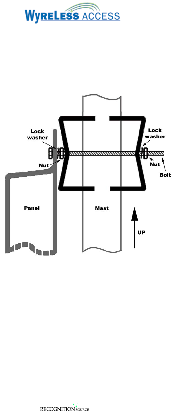
4.3.1.1 Install the 3” bolts in the top mounting holes from the front side of the ANT-6DB-FLAT. Secure
the bolts using lock washers and nuts. Install half of a clamp over the bolts from the back side of
the ANT-6DB-FLAT. Making certain that the “V” portion of the half clamp is pointing away
from the ANT-6DB-FLAT. (Figure 4-3)
NOTE: Only tighten the nuts enough to firmly fasten the bolts to the ANT-6DB-FLAT.
Over tightening will deform the ANT-6DB-FLAT and may affect performance.
Figure 4-3 – Mast Mounting Clamp Install
4.3.1.2 Repeat step 4.3.1.1 to install half of a clamp to the bottom mounting holes of the ANT-6DB-
FLAT.
4.3.1.3 Position the ANT-6DB-FLAT on the mast. (Figure 4-3)
4.3.1.4 Install the other half of a clamp on the back side of the mast at the top mounting position lock
washers and nuts. Make certain that the “V” portion of the half clamp is pointing toward the
mast. (Figure 4-3)
4.3.1.5 Repeat step 4.3.1.4 to install half of a clamp to the bottom mounting position of the ANT-6DB-
FLAT.
4.3.2 Flat Surface Mounting
4.3.2.1 Place the ANT-6DB-FLAT against the surface where it is to be mounted.
4.3.2.2 Using ANT-6DB-FLAT enclosure as a template, mark the four mounting holes.
4.3.2.3 Drill a 9/32” hole in the surface at each mounting mark, 1 ¾” deep.
4.3.2.4 Insert the four anchors provided firmly into the holes so they are flush with the surface.

3820 Stern Avenue
St. Charles, IL 60174
(630) 762-4450
P/N: M053-xxx-x001 (630) 762-4444 fax Page 14 of 29
4.3.2.5 Fasten the ANT-6DB-FLAT enclosure to the mounting surface using the screws & washers
provided.
4.4 Connecting the ANT-6DB-FLAT Coax
For instructions on how to connect the ANT-6DB-FLAT Coax to the PIM or WRI, proceed to section 5,
page 15.
3820 Stern Avenue
St. Charles, IL 60174
(630) 762-4450
P/N: M053-xxx-x001 (630) 762-4444 fax Page 15 of 29
5. Connecting the Coax
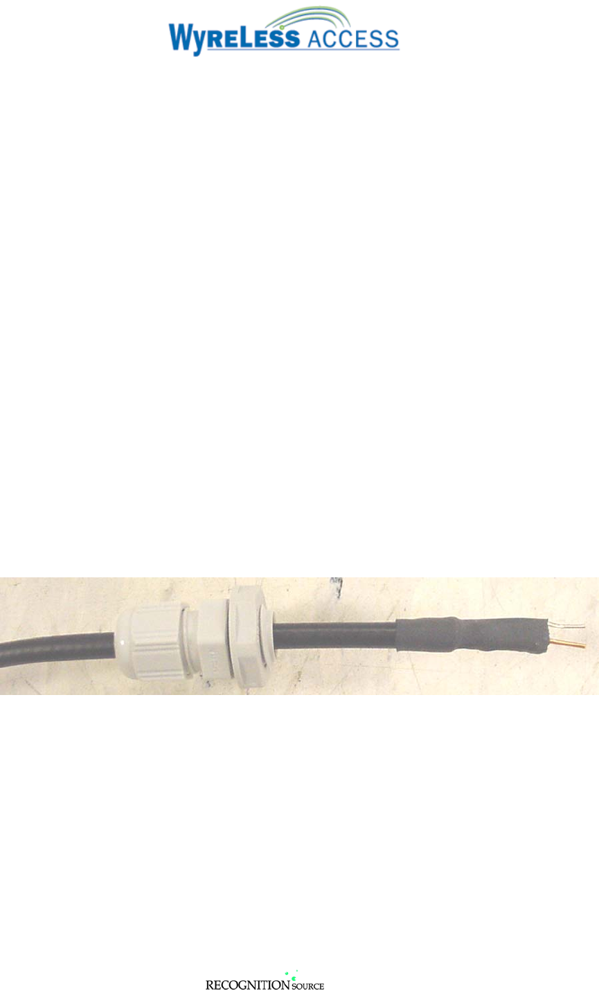
All RAM’s come with a 15’ coax. One end of the coax is terminated with a male N connector, the other end
is terminated as shown in Figure 5-5.
Note: Earlier versions of the ANT-REMOTE had the coax already connected to the antenna eliminating the
male N connector.
5.1 Grounding & Lightning Protection Consideration
WARNING: Make certain that the Coax installation conforms to all electrical codes (national and
local) regarding grounding and lightning protection requirements.
PolyPhaser’s Technical Information section of their web site (www.polyphaser.com ) contains
excellent information about grounding and lightning protection.
Refer to section 2, page 7, above
If the remote antenna will be used indoors then grounding and lightning protection may not be needed,
consult local codes.
Grounding and lightning protection components compatible with all Recognition Source Remote
Antennae are available accessories, see Table 1-2, on page 5 above
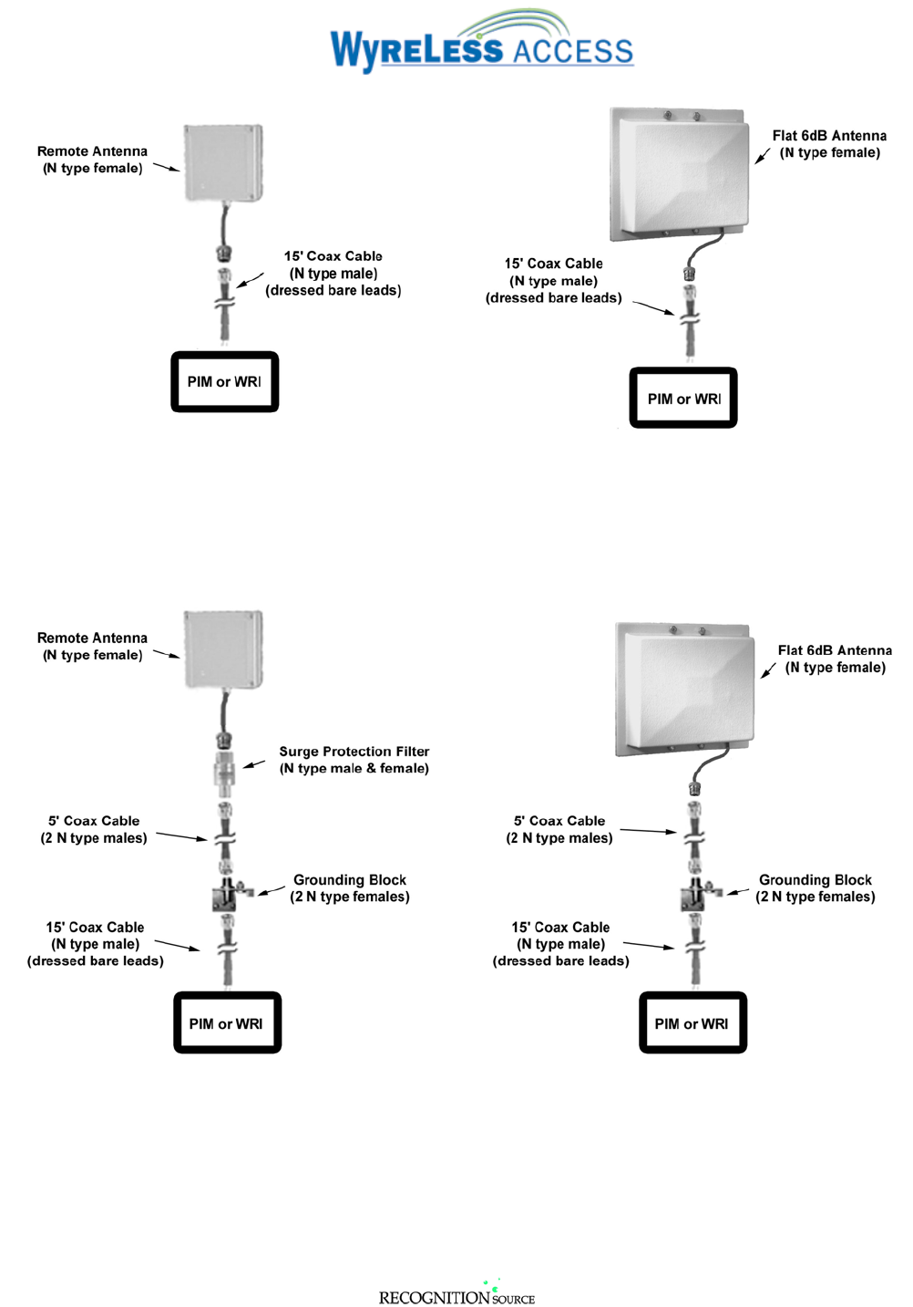
Figure 5-1 & Figure 5-2 show the recommended connections for each antenna when no grounding and no
lightning protection are required.
Figure 5-3 & Figure 5-4 show the recommended connections for each antenna when grounding and
lightning protection are required.
NOTE: When using a Grounding Block, it must be electrically connected to an earth ground that
meets local code requirements. Refer to the grounding block manufacturer’s instructions for
further information.
3820 Stern Avenue
St. Charles, IL 60174
(630) 762-4450
P/N: M053-xxx-x001 (630) 762-4444 fax Page 16 of 29
Figure 5-1 - ANT-REMOTE No Protection
Figure 5-2 - ANY-6DB-FLAT No Protection
Figure 5-3 - ANT-REMOTE Recommended Protection
Figure 5-4 - ANT-6dB-FLAT Recommended Protection
3820 Stern Avenue
St. Charles, IL 60174
(630) 762-4450
P/N: M053-xxx-x001 (630) 762-4444 fax Page 17 of 29
5.2 Weatherproofing Coax Connections
The Lightning Protection Kit (ANT-LPK) includes weatherseal tape that must be used on all coax
connections that are exposed to weather.
5.3 Routing the Coax
The RAM’s Coax is suitable for outdoor and aerial installations. Route the RAM’s Coax so that there are
a minimum number of bends. When the RAM’s Coax must bend, make certain that the bend’s radius is
greater than 2”.
5.4 Dressing the Coax
NOTE: The RAM is supplied with a proper termination at the end of the 15’ Coax (Figure 5-5). Use
the Coax as supplied. DO NOT CUT COAX TO LENGTH!
Dress excess coax in a coil no less than 8” in diameter.
NOTE: Do not place the excess coax inside the RAM, PIM, or WRI enclosure.
5.5 Terminating the Coax at the RAM
5.5.1 If used, mount a lightning protection device (section 5.1) directly to the female N connector on the
antenna.
5.5.2 Connect the male N connector end of the coax to the female N connector of the lightning protection
device (if used) or antenna.
5.5.3 Make certain that all the N connectors are tightly fastened. Loose connections will affect performance
5.5.4 If required, weatherize the lightning protection device.
5.6 Terminating the Coax at the PIM or WRI
NOTE: The RAM is supplied with a proper termination at the end of the 15’ Coax (Figure 5-5). Use
the Coax as supplied. DO NOT CUT COAX TO LENGTH!
Figure 5-5 – Factory Supplied Coax Termination at PIM or WRI
5.7 Connecting Coax to a PIM or PIME
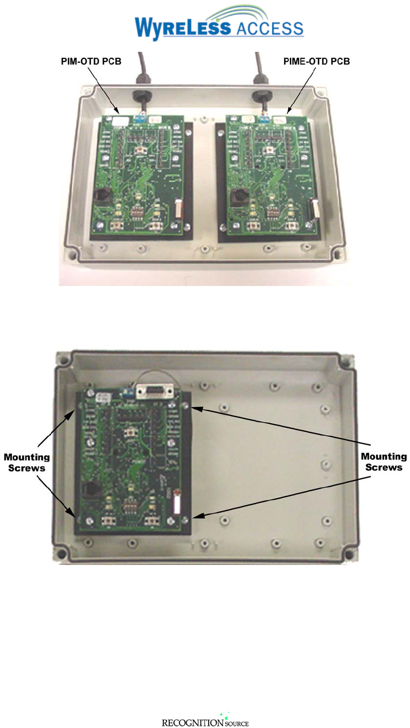
The following basic installation procedure applies to installing a RAM on a PIM-OTD or a PIME-OTD.
The PIM-OTD PCB is located on the left side of the PIM-OTD enclosure and the PIME-OTD PCB is
located on the right side of the PIM-OTD enclosure.
3820 Stern Avenue
St. Charles, IL 60174
(630) 762-4450
P/N: M053-xxx-x001 (630) 762-4444 fax Page 18 of 29
Figure 5-6 – PIM & PIME with RAMs Installed
5.7.1 Remove the PIM PCB from the PIM-OTD enclosure by removing the four screws, one in each corner
of the PIM PCB back plate (Figure 5-7).
Figure 5-7 – Removing PIM PCB
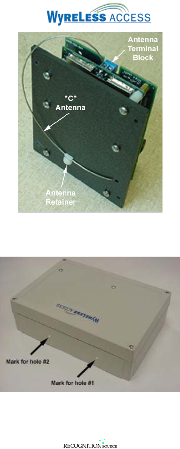
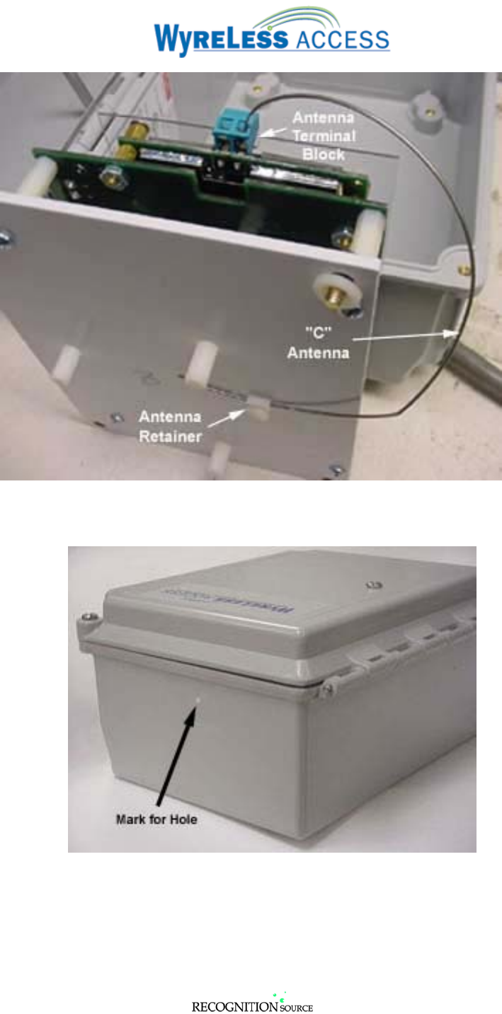
5.7.2 Remove the PIM’s internal “C” antenna by loosening the screw on the Antenna Terminal Block and
gently pulling the antenna out of the Antenna Retainer (Figure 5-8).
Note: Some PIM internal “C” antennae may also be secured with RTV adhesive. This adhesive
can be easily broken free from the back plate with a little twisting.
3820 Stern Avenue
St. Charles, IL 60174
(630) 762-4450
P/N: M053-xxx-x001 (630) 762-4444 fax Page 19 of 29
Figure 5-8 – Removing the PIM’s Internal “C” Antenna
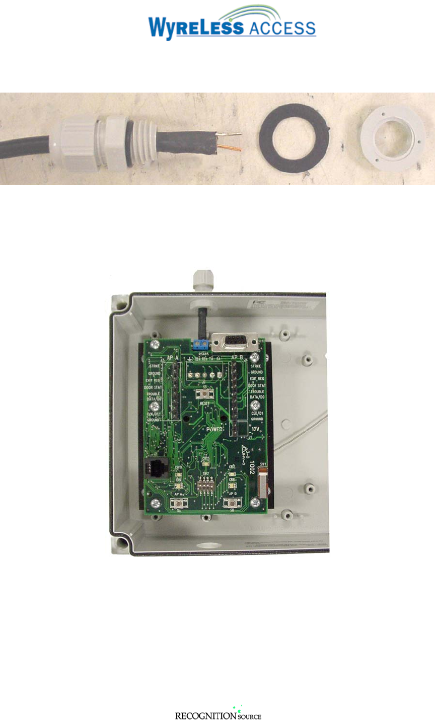
5.7.3 Drill a ½” hole in the top of the PIM-OTD enclosure (Figure 5-9).
NOTE: Drill hole #1 for a PIM-OTD, hole #2 for a PIME-OTD.
Figure 5-9 – PIM-OTD Antenna Hole Locations
3820 Stern Avenue
St. Charles, IL 60174
(630) 762-4450
P/N: M053-xxx-x001 (630) 762-4444 fax Page 20 of 29
5.7.4 Replace the PIM PCB in the PIM-OTD enclosure (Figure 5-7).
5.7.5 Remove the nut and washer (if provided) from the NEMA gland (Figure 5-11). Discard the waher.
Figure 5-10 – NEMA Gland with Nut & Washer Removed
5.7.6 Install the NEMA gland in the hole drilled in step 5.7.3. Tighten the gland by turning the nut inside
the enclosure. Do not tighten the gland by turning the gland while holding the nut. There is an “O”
ring on the gland that will not seat properly if the gland is rotated (Figure 5-11).
Figure 5-11 – Installing the RAM Coax in the PIM
3820 Stern Avenue
St. Charles, IL 60174
(630) 762-4450
P/N: M053-xxx-x001 (630) 762-4444 fax Page 21 of 29
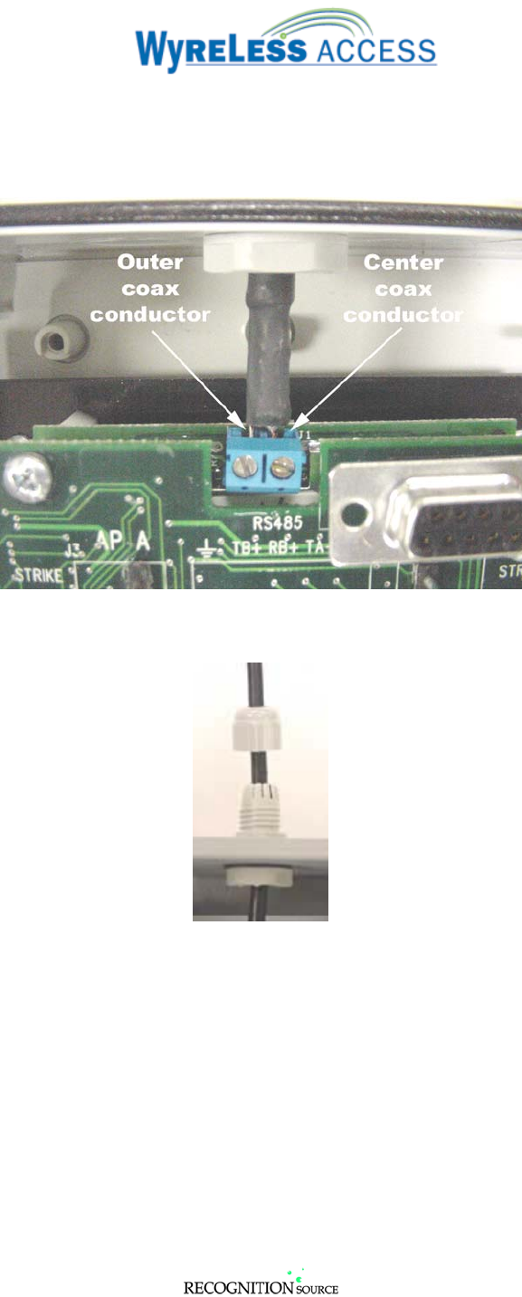
5.7.7 Attach the Remote Antenna Coax to the PIM PCB Antenna Terminal Block (Figure 5-12).
NOTE: Make certain that the Outer Coax Conductor (silver color) goes in the leftmost
terminal of PIM PCB Antenna Terminal Block and that the Center Coax Conductor (copper
color) goes in the rightmost terminal.
Figure 5-12 – PIM PCB Antenna Terminal Block Connections
5.7.8 Secure the Remote Antenna Coax in the NEMA gland (Figure 5-13).
Figure 5-13 – Securing the PIM’s Antenna NEMA Gland

3820 Stern Avenue
St. Charles, IL 60174
(630) 762-4450
P/N: M053-xxx-x001 (630) 762-4444 fax Page 22 of 29
5.8 Connecting Coax to a WRI
5.8.1 Remove the WRI PCB from the WRI-OTD enclosure by removing the four screws, one in each corner
of the PIM PCB back plate (Figure 5-14).
Figure 5-14 – Removing the WRI PCB
5.8.2 Remove the WRI’s internal “C” antenna by loosening the screw on the Antenna Terminal Block and
gently pulling the antenna out of the Antenna Retainer.
Note: Some PIM internal “C” antennae may also be secured with RTV adhesive. This adhesive
can be easily broken free from the back plate with a little twisting.
3820 Stern Avenue
St. Charles, IL 60174
(630) 762-4450
P/N: M053-xxx-x001 (630) 762-4444 fax Page 23 of 29
Figure 5-15 – Removing the WRI’s Internal “C” Antenna
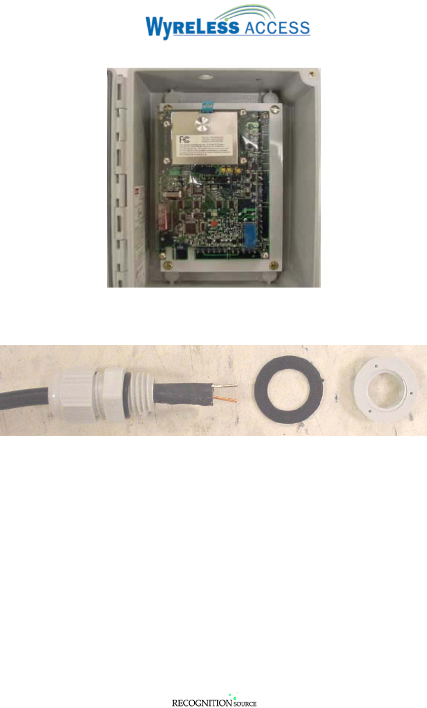
5.8.3 Drill a ½” hole in the top of the WRI-OTD enclosure (Figure 5-16).
Figure 5-16 – WRI -OTD Antenna Hole Locations
3820 Stern Avenue
St. Charles, IL 60174
(630) 762-4450
P/N: M053-xxx-x001 (630) 762-4444 fax Page 24 of 29
5.8.4 Replace the WRI PCB in the WRI-OTD enclosure (Figure 5-17).
Figure 5-17 – Replacing the WRI’s PCB
5.8.5 Remove the nut and washer (if provided) from the NEMA gland (Figure 5-18). Discard the washer.
Figure 5-18 – NEMA Gland with Nut & Washer Removed
3820 Stern Avenue
St. Charles, IL 60174
(630) 762-4450
P/N: M053-xxx-x001 (630) 762-4444 fax Page 25 of 29
5.8.6 Install the NEMA gland in the hole drilled in step 5.8.3. Tighten the gland by turning the nut inside
the enclosure. Do not tighten the gland by turning the gland while holding the nut. There is an “O”
ring on the gland that will not seat properly if the gland is rotated (Figure 5-19).
Figure 5-19 – Installing the RAM Coax in the WRI
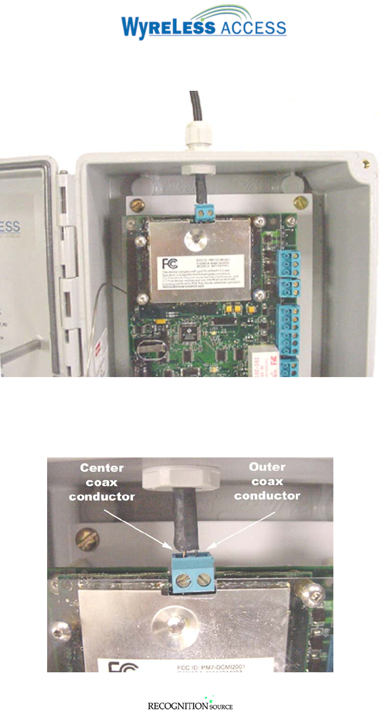
5.8.7 Attach the Remote Antenna Coax to the WRI PCB Antenna Terminal Block (Figure 5-20).
NOTE: Make certain that the Center Coax Conductor (copper color) goes in the leftmost
terminal of WRI PCB Antenna Terminal Block and that the Outer Coax Conductor (silver
color) goes in the rightmost terminal.
Figure 5-20 – WRI PCB Antenna Terminal Block Connections
3820 Stern Avenue
St. Charles, IL 60174
(630) 762-4450
P/N: M053-xxx-x001 (630) 762-4444 fax Page 26 of 29
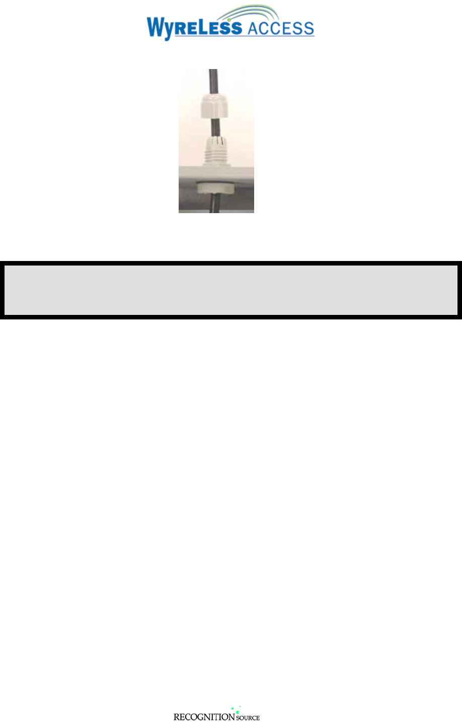
5.8.8 Secure the Remote Antenna Coax in the NEMA gland (Figure 5-21).
Figure 5-21 – Securing the WRI’s Antenna NEMA Gland
This completes the Remote Antenna Module Installation.
Refer to the “Configuring & Operating a Wyreless Access System” manual to test the
installation.

3820 Stern Avenue
St. Charles, IL 60174
(630) 762-4450
P/N: M053-xxx-x001 (630) 762-4444 fax Page 27 of 29
6. FCC Compliance & Warnings
6.1 FCC Compliance
• This device has been authorized by the FCC Rules and Industry Canada.
• This device complies with the limits for a Class B digital device and a Class B intentional radiator,
pursuant to Part 15 of the FCC Rules and with RSS-210 of Industry Canada. Operation is subject to
the following two conditions: (1) This device may cause harmful interference, and (2) this device
must accept any interference received, including interference that may cause undesired operation.
• The Wyreless Access System Component must be installed by qualified professionals or contractors
in accordance with FCC part 15.203, Antenna Requirements.
• Do not use any antenna other than the one provided with the unit.
6.2 Warnings
• RF Exposure - To comply with FCC RF exposure requirements for mobile transmitting devices this
transmitter should only be used or installed at locations where there is normally at least a 20 cm
separation between the antenna and all persons.
• Do not co-locate and operate in conjunction with any other antenna or transmitter.
• Changes or modifications not expressly approved by Recognition Source could void the user’s
authority to operate the equipment.
3820 Stern Avenue
St. Charles, IL 60174
(630) 762-4450
P/N: M053-xxx-x001 (630) 762-4444 fax Page 28 of 29
7. Contacting Recognition Source
For questions regarding Wyreless Access ™:
(630) 762-4450
(630) 762-4444 fax
3820 Stern Avenue
St. Charles, IL 60174
(630) 762-4450
P/N: M053-xxx-x001 (630) 762-4444 fax Page 29 of 29
8. Revision History
Version Date Changes
X001 12/05/03 preliminary in house release for comments