Recognition Source IRL2001 Access System Transmitter User Manual Procedures
Recognition Source, LLC Access System Transmitter Procedures
Contents
Manual

i
Wyreless Access TM Pre-Production System 6-20-01
Setup and Operating Procedures
1. Introduction
This manual has been designed to help you understand the operation of
your Wyreless Access TM Pre-Production System. Please familiarize
yourself with the system and its parts before operating. The system
includes one Door Control Module Interface (DCMI), one mounted
Integrated Reader Lock (IRL) and one Accessory Kit.
The information provided is preliminary and will change. This system is a
pre-production system. It is not intended to be a full-feature system.
Please see section 21, Pre-Production System Limitations for a more
complete description of its limitations.
For questions not answered by this manual regarding the setup and
operation of the Wyreless Access Pre-Production System, please contact
_________________________________________________________
2. FCC Compliance
This device is designed to comply with Part 15 of the FCC Rules and with
RSS-210 of Industry Canada. Operation is subject to the following two
conditions: (1) This device may cause harmful interference, and (2) this
device must accept any interference received, including interference that
may cause undesired operation. This equipment will be tested to comply
with the limits for a Class B digital device and a Class B intentional
radiator, pursuant to Part 15 of the FCC Rules.
Warning
Changes or modifications not expressly approved by the party responsible
for compliance could void the user’s authority to operate the equipment.
This device has not been authorized by the FCC Rules. This device is
not, and may not be, offered for sale or lease or sold or leased until
authorization is obtained.
3. Warnings
• RF exposure – To comply with FCC RF exposure requirements for
portable transmitting devices this transmitter should only be used or
installed at locations where there is at least a 20 cm separation
between the antenna and all persons.
• Use only the Battery Pack specified in this instruction manual.
• Do not subject Battery Pack to fire or high temperatures.
• Do not attempt to recharge, short or disassemble Battery Pack.
• Follow local regulations for battery disposal.
• Immediately remove the batteries and discontinue use if:
• The product is impacted after which the interior is exposed,
• The product emits a strange smell, heat or smoke.
Do not disassemble. If unit stops working or disassembly is needed,
contact Recognition Source at 630-762-4450 for instructions.
!
ii
Table of Contents
1. INTRODUCTION I
2. FCC COMPLIANCE I
3. WARNINGS I
TABLE OF CONTENTS II
4. GENERAL DESCRIPTION 1
4.1 COMPONENTS OF THE WYRELESS ACCESS SYSTEM 1
4.1.1 Door Control Module Interface (DCMI) 1
4.1.2 Integrated Reader Lock (IRL) 1
4.1.3 Accessory Kit 1
4.2 OPERATING OPTIONS 1
4.2.1 Stand-Alone Operation 1
4.2.2 Panel-Connected Operation 2
4.3 CARD SWIPE 2
5. DCMI PART NAMES 2
2

iii
6. DCMI PCB FUNCTIONAL COMPONENTS 3
6.1 8-PIN HEADERS 3
6.2 TACTILE SWITCHES 3
6.3 2-PIN HEADER 3
6.4 3-PIN HEADER 3
6.5 4-SWITCH DIPSWITCH 4
6.6 LEDS 4
7. IRL PART NAMES 4
8. IRL FUNCTIONAL COMPONENTS – 5
8.1 TORX BOSS 5
8.2 BATTERY WIRE HARNESS 5
8.3 PROGRAMMING WIRE HARNESS 5
9. ACCESSORY KIT PART NAMES 6
10. ACCESSORY KIT 6
10.1 BATTERY PACK 6
10.2 BATTERY OVERRIDE CABLE 6
11. DCMI SETUP FOR STAND-ALONE MODE 7
11.1 STAND-ALONE MODE, DCMI SIMULATES A PANEL 7
SO THAT THE SYSTEM CAN BE TESTED AND EVALUATED WITHOUT A PANEL, THE PRESENCE OF A PANEL MUST BE
SIMULATED. WIRING A JUMPER BETWEEN THE STRIKE AND GROUND (TOP TWO) PINS OF EACH 8 POSITION
TERMINAL BLOCK (ON HEADERS J3 & J4) ON THE DCMI PCB WILL SIMULATE A PANEL. SEE FIGURE 5. 7
11.2 POWER TO THE DCMI IN STAND-ALONE MODE 7
12. DCMI SETUP FOR PANEL-CONNECTED MODE 8
13.1 COMMUNICATIONS OVERVIEW 9
13.2 HOW TO SET TO AN RF CHANNEL 9
14. LINK MODE 10
14.1 LINKING 10
14.2 LINK PROCESS 10
14.3 HOW TO PUT THE DCMI INTO LINK MODE 10
15. IRL LINKING TO THE DCMI VIA BATTERY CONNECTION 11
15.1 OVERVIEW 11
15.2 CONNECT THE IRL BATTERY PACK TO INITIATE LINKING TO THE DCMI 11
16. WHEN AND HOW TO CHANGE THE RF CHANNEL 12

iv
17. UNDERSTANDING THE DCMI’S LED INDICATORS 12
18. UNDERSTANDING THE IRL’S LED INDICATORS AND INTERNAL SOUNDER 13
19. OPERATING THE WYRELESS ACCESS SYSTEM 14
19.1 OVERVIEW 14
19.2 CARD SWIPING 14
19.3 INDICATIONS OF A SUCCESSFUL CARD SWIPE 15
19.4 INDICATION OF AN UNSUCCESSFUL CARD SWIPE 15
19.5 INDICATIONS OF A SUCCESSFUL REQUEST-TO-UNLOCK (CARD SWIPE) 15
19.6 INDICATIONS OF AN UNSUCCESSFUL REQUEST-TO-UNLOCK (CARD SWIPE) 16
20. OTHER SOFTWARE FEATURES 16
•• SENSES AND REPORTS DOOR POSITION TO THE PANEL. 16
•• PERIODICALLY REPORTS TO PANEL FOR “HOUSEKEEPING” UPDATES – ¼, ½, 1, 2, 5 OR 15 MINUTES
INTERVALS, CONFIGURABLE. BATTERY LIFE IS A FUNCTION OF THIS TIME PERIOD AND NUMBER OF CARD
SWIPES. REQUEST-TO-EXIT. 16
21. PRE-PRODUCTION SYSTEM LIMITATIONS 17
•• FCC – DOES NOT HAVE FCC APPROVAL. 17
•• UL – DOES NOT HAVE UL APPROVAL. 17
•• SHOCK AND VIBRATION – SHOCK AND VIBRATION TESTS HAVE NOT BEEN COMPLETED. 17
•• LINK MODE ATTENUATED BY 3DB – FEATURE HAS NOT BEEN IMPLEMENTED. 17
•• LOW BATTERY INDICATION AT THE PANEL – FEATURE HAS NOT BEEN IMPLEMENTED. 17
•• INTERNAL CACHE MEMORY – FEATURE IS NOT IMPLEMENTED. 17
•• IRL READER TAMPER SWITCH – FEATURE HAS NOT BEEN IMPLEMENTED. 17
•• DCMI TAMPER SWITCH – FEATURE HAS NOT BEEN IMPLEMENTED. 17
•• RS 485 COMMUNICATION PROTOCOL TO THE PANEL – SCHEDULED FOR RELEASE 2. 17
22. CARE AND USAGE 17
•• ALWAYS OPERATE THE WYRELESS ACCESS PRE-PRODUCTION SYSTEM WITHIN INSTRUCTIONS AND
SPECIFICATIONS DESCRIBED IN THIS MANUAL. 17
•• KEEP THE DCMI DOOR AND IRL BATTERY COMPARTMENT CLOSED WHEN IN USE. 17
•• DO NOT USE THE SYSTEM OUTDOORS. 17
•• DO NOT PAINT ANY PART, ESPECIALLY THE DCMI ANTENNA OR IRL ANTENNA COVER. 17
23. SPECIFICATIONS: 17
23.1 BOTH COMPONENTS 17
23.2 IRL 17
23.3 DCMI 17
24. TROUBLESHOOTING 18
25. OTHER INSTALLATION REQUIREMENTS 19
v
CODE OF FEDERAL REGULATIONS 19
1
4. General Description
Wyreless Access TM is a wireless access control peripheral system. Simply, it allows
a panel to control a remote door without any wiring from the panel to the door or
any wiring at or around the door. The system consists of two components: a
Door Control Module Interface (DCMI) and an Integrated Reader Lock (IRL). It communicates
using 900 MHz RF Spread Spectrum Technology. An Accessory Kit is also provided.
4.1 Components of the Wyreless Access System
4.1.1 Door Control Module Interface (DCMI)
The DCMI includes (1) an RF receiver and transmitter (transceiver) to
communicate with an IRL and (2) an interface to an access control
panel. The DCMI will interface with any access panel using either
Magstripe (clock & data) or Wiegand (data1/data 0) compatible inputs.
One DCMI is capable of controlling two IRLs. A Door Control
Module Interface–Expanded (DCMIE), capable of controlling four
IRLs, is also available.
4.1.2 Integrated Reader Lock (IRL)
The IRL includes 7 components: an electrical lock plus reader,
power supply, optional door position contacts and Request-to-Exit
sensor. It also includes an RF receiver and transmitter
(transceiver). The IRL mounts on a standard cylindrical-cut door
(IRLs for mortise-cut doors will be available soon).
4.1.3 Accessory Kit
The Accessory Kit contains a portable doorjamb with the IRL mounted
on it. This will not be provided in the production version.
The Kit also includes two battery packs of four AA alkaline batteries
and one connector each. A single battery pack of eight AA alkaline
batteries and one connector will be provided in production versions.
A Battery Override Cable, 9VBOC, will also be supplied.
4.2 Operating Options
The pre-production system operates in two ways: Stand-Alone Operation
or Panel-Connected Operation.
4.2.1 Stand-Alone Operation
Stand-Alone involves only the IRL and DCMI. In Stand-Alone, the
IRL transmits a Request-to-Unlock after a card swipe. The DCMI
receives this request then transmits back an unlock command.
This mode is intended for evaluating basic communications
performance levels.
2
4.2.2 Panel-Connected Operation
Panel Connected Operation requires connection to an access control
panel with Magstripe (clock & data) or Wiegand (data1-data0) protocol.
After a card swipe, the IRL transmits a Request-to-Unlock. The DCMI
receives this request and communicates it to the panel via wires.
When the panel responds with an unlock command, the DCMI
receives the command via wires and transmits it to the IRL via RF.
4.3 Card Swipe
Pre-production units have Magstripe readers. Wiegand & Prox readers will be available.
Manual Card Swipe is required for either Stand-Alone or Panel-Connected Operation. The
user must swipe a card to begin a transmission. Only when a card has been swiped will
the IRL transmit a Request-to-Unlock. In Stand Alone mode, a mag stripe card with Track
2 data will be needed to transmit a valid Request-to-Unlock. In Panel-Connected mode, a
valid card must be used to result in a valid Request-to-Unlock, like normal.
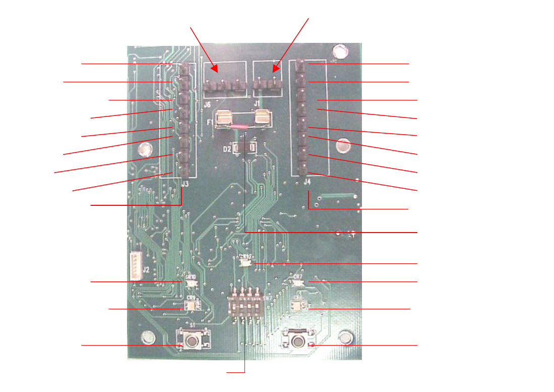
5. DCMI Part Names
STRIKE
GROUND
REQUEST-TO-EXIT
DOOR STATUS
TROUBLE
DATA
CLOCK
GROUND
485 Bus
3-PIN HEADER, J6
(GRND, A, B)
STRIKE
GROUND
REQUEST-TO-EXIT
DOOR STATUS
TROUBLE
DATA
CLOCK
GROUND
8-PIN HEADER, J3
8-PIN HEADER, J4
TACTILE
SWITCH, S1
Door A
TACTILE
SWITCH, S2
Door B
LED (GRN-RED), CR9
LED (RED), CR10 LED (RED), CR7
LED (GRN-RED), CR6
LED (GRN), CR15
Power
–
supplied by panel
2-PIN HEADER, J1 (Power)
4-POLE, DIPSWITCH, SW7
Figure 1- DCMI Printed Circuit Board (PCB)
FUSE
+ + --
3
6. DCMI PCB Functional Components
As previously stated, the DCMI is capable of controlling two IRLs. The
components on the left side of the DCMI PCB will be designated for IRL A while
components on the right will be designated for IRL B.
The following text describes the functions of the PCB components - Figure 1.
Note – All headers (male terminal pin strips) will have terminal blocks attached.
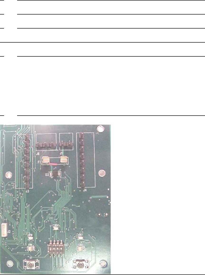
6.1 8-Pin Headers
There are two 8-pin headers, one for each door. The left 8-pin header is
marked J3, and the right, J4. (J3 applies to IRL A; J4 applies to IRL B.)
The 8-pin header provides either 1) the connections to a panel for Panel
Operation or 2) the two pins (noted as Strike and Ground) needed to be
connected together in order for the DCMI to function in Stand-Alone
Operation. Figure 1 notes the function of each pin on the 8-pin header.
6.2 Tactile Switches
Two tactile switches (S1 and S2) are located on the DCMI PCB. Again,
the tactile switch on the left (S1) applies to IRL A, and the tactile switch on
the right (S2) applies to IRL B.
The tactile switch is used to put the DCMI into Link Mode.
When the DCMI is in Link Mode, it is in receive mode, waiting for the first
link request transmission from an IRL in order to link the IRL and DCMI so
that the system can be operated. The switch can also be used to take the
DCMI out of Link Mode. More detailed information on Link Mode follows
in section 14, Link Mode.
6.3 2-Pin Header
One 2-pin header (J1) is located to the left of the 8-pin header (J4).
The 2-pin header is always the connection to the panel power in either the
Stand-Alone Mode or the Panel-Connected Mode. Plus is left pin,
negative is right pin.
6.4 3-Pin Header
One 3-pin header (J6) is located to the right of the 8-pin header (J3).
This is for a future RS 485 interface to a control panel and for local
troubleshooting and configuration. The left pin is ground, the center pin is
A, and the right pin is B.
4
6.5 4-Switch Dipswitch
There is one 4-pole dipswitch (SW7). The dipswitch determines the RF
channel to be used. As there is only one dipswitch, doors A and B will
communicate on the same RF channel.
6.6 LEDs
The following describes the seven LEDs and the messages they convey.
6.6.1 Green LED, CR15, when blinking, indicates the microprocessor is
running and power is on.
Note: If the power is off, CR15 may still be blinking but the
microprocessor is not running.
6.6.2 Red LEDs, CR10 and CR7, indicate Trouble at its respective IRL
such as Low Battery, Tamper, No Communication.
6.6.3 CR9 and CR6 are dual green and red LEDs. Each indicates either
Link Mode or Standby Mode for its respective IRL. When in Link
Mode, the green and red LEDs flash alternately. When in Standby
Mode, the green LEDs illuminate continuously.
6.6.4 Green and red LEDs, CR9 and CR6, also indicate RF
communication. The red LED will flash once per sent transmission.
The green LED flashes once per received transmission. See
Section 18, Understanding the IRL’s LED Indicators and
Internal Sounder.
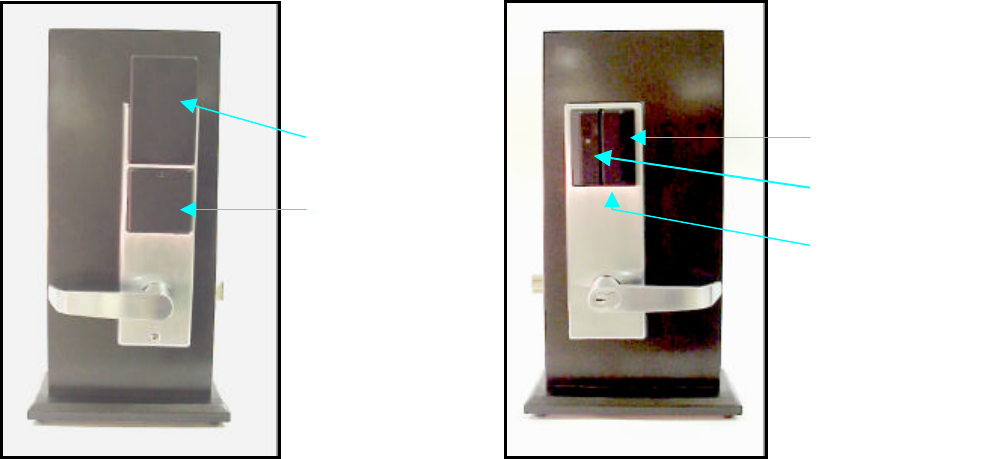
7. IRL Part Names
Figure 2
Mag Stripe
Reader
Antenna Cover
Battery Cover Reader LED
Auxiliary
Battery Socket
5
8. IRL Functional Components –
The Antenna Cover, Battery Cover, Reader, Reader LED and Auxiliary Battery
Socket are shown in Figure 2.
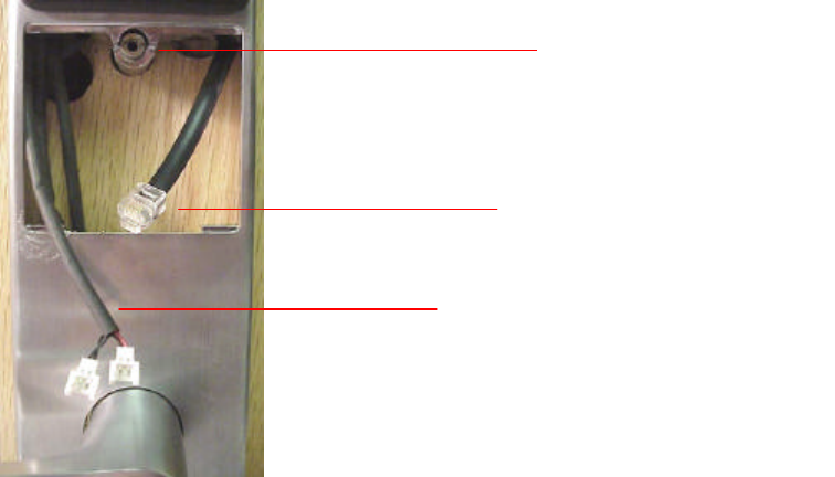
Figure 3
The following describes various other components that make up the IRL -
Figure 3
8.1 Torx Boss
A Torx screw secures the Battery Cover. It fits into the top center of the
battery cover and screws into the Torx boss.
Note: This requires a Torx security screwdriver (size T9).
8.2 Battery Wire Harness
The Battery Wire Harness is located in the battery compartment. It is the
wire harness that has two, 2-position connectors at the end. These
connectors connect to the Battery Packs that supply power to the IRL.
8.3 Programming Wire Harness
The Programming Wire Harness is located in the battery compartment. It
is the wire harness with the RJ11 (6 pin, 6 wire) connector.
The Programming Wire Harness connects the IRL PCB through any
programming module to any computer via the serial data port. When the
Programming Wire Harness is connected, new software versions can be
loaded into the flash memory. Instructions will be provided when needed.
PROGRAMMING
WIRE HARNESS
BATTERY WIRE HARNESS
TORX BOSS
(is also the Combination
Mounting Screw)
6
9. Accessory Kit Part Names
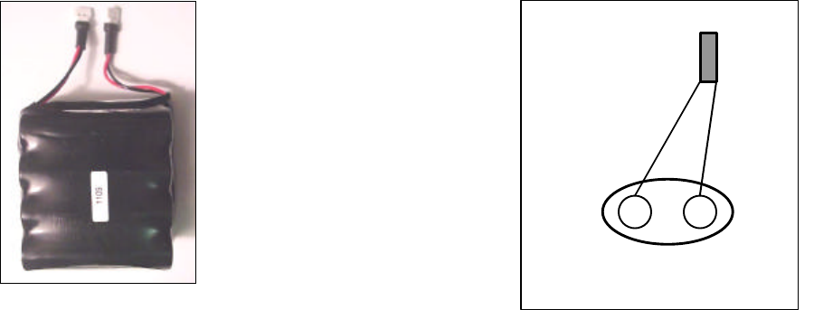
9Volt Battery Connector
Battery Pack Battery Override Cable
(9VBOC)
Figure 4
10. Accessory Kit
The Accessory Kit (Figure 4) is provided for the convenience of the user. The
following are the components provided and descriptions of their function.
10.1 Battery Pack
The two battery packs with two connectors is the power supply for the IRL.
They connect to the Battery Wire Harness located in the IRL battery
compartment. The connectors are polarized.
10.2 Battery Override Cable
A Battery Override Cable, 9VBOC, is needed to plug a standard 9.0V
battery, 522 or equal, into the jack under the reader if the internal IRL
battery goes dead. This cable is available from Recognition Source but is
not part of this Accessory Kit. Call 630-762-4450 if one is needed.
PLUG
wires
7
11. DCMI Setup for Stand-Alone Mode
11.1 Stand-Alone Mode, DCMI Simulates a Panel
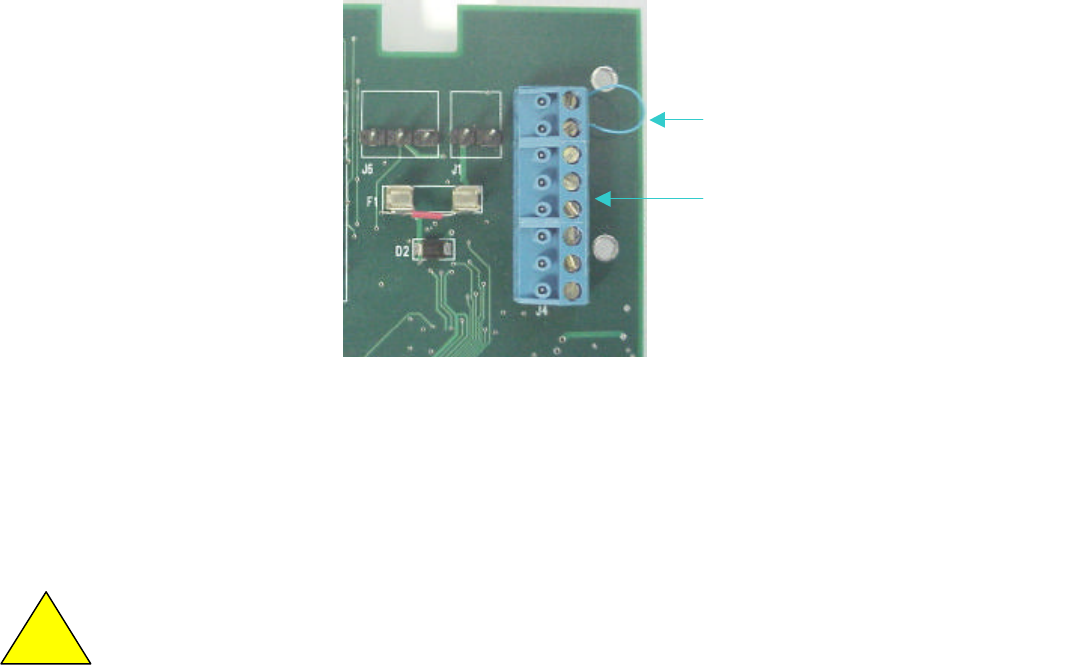
So that the system can be tested and evaluated without a panel, the
presence of a panel must be simulated. Wiring a jumper between the
Strike and Ground (top two) pins of each 8 position terminal block (on
headers J3 & J4) on the DCMI PCB will simulate a panel. See Figure 5.
Proper jumper wiring of J4 for simulating a panel, J3 is the mirror image.
Figure 5
11.2 Power to the DCMI in Stand-Alone Mode
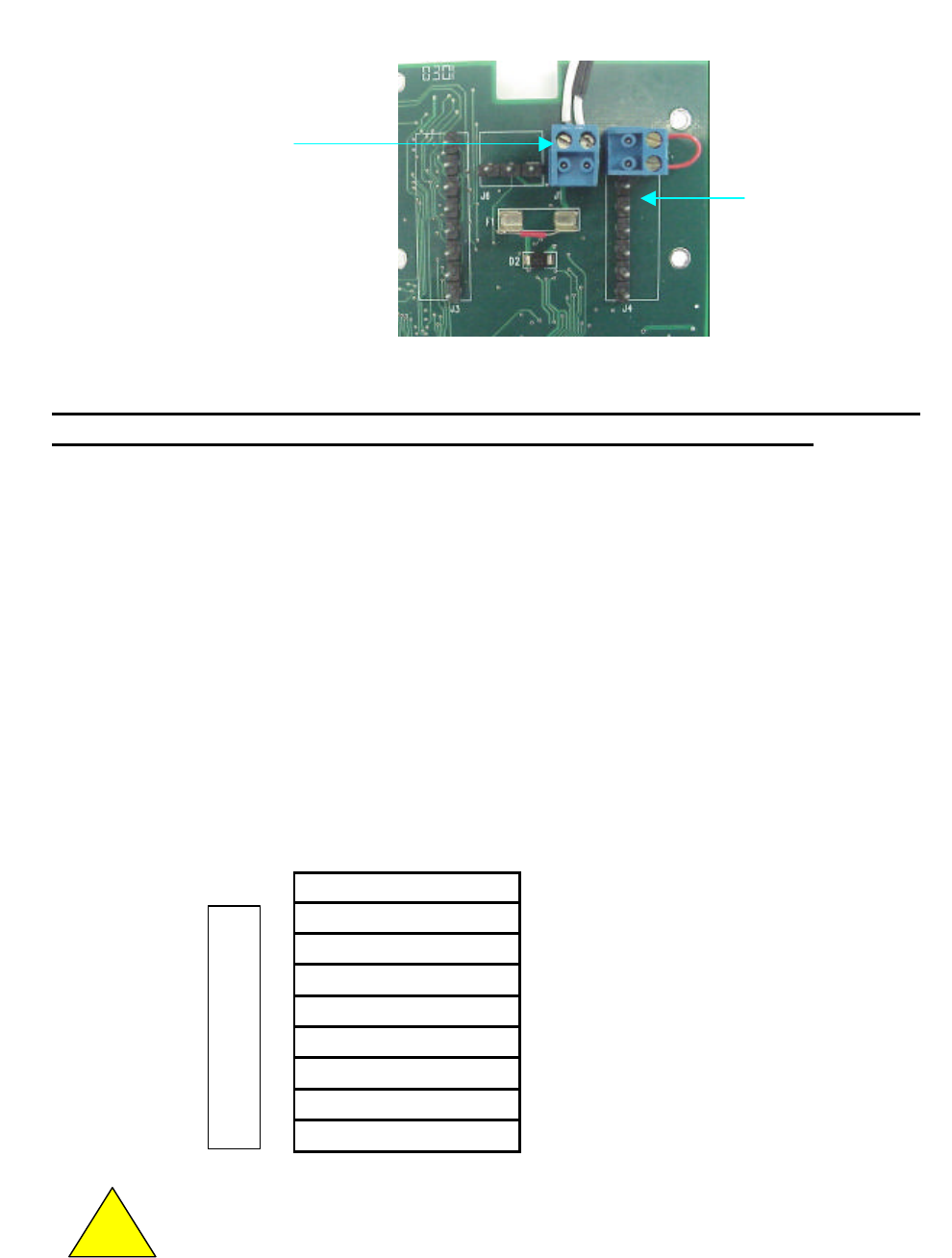
11.2.1 Locate the 2-pin header (J1) (to the left of the 8-pin header, J4).
11.2.2 Plug the 2-position terminal block, header (J1) as shown. See
Figure 6.
CAUTION: The voltage polarity cannot be reversed w/o damage to the unit.
11.2.3 Connect the panel 12 VDC supply to J1.
11.2.4 The microprocessor LED (CR15) will blink green and the Link
Mode/Standby LEDs (CR9 & CR6) will illuminate solid green.
!
Jumper Wire
shorting top two pins
Terminal Block
(on header)
8
Figure 6
Proceed to Section 13, RF Channel Selection, and go on. When done with the
Stand-Alone Mode return here to start the Panel-Connected Mode.
12. DCMI Setup for Panel-Connected Mode
12.1 Panel-Connected Mode, DCMI Wired to a Panel
Power is connected to the same two terminals of J1. Power to be
supplied from a power source in the panel. A power source from the
panel must be 12.0 VDC nominal at 250 ma. minimum.
The 8-position terminal block (Fig.5) provides the signal connections to the
panel. One is on J3 & one on J4. The chart below indicates the names
and/or functions of each pin. For connection instructions for a specific
panel, call 630-762-4450.
Note: Shielded cable must be used when wiring a DCMI to a panel.
J3, J4 Name/function
• Strike
• Ground
• Request-to-Exit
• Door Status
• Trouble
• Data 1- Data 0
• Clock & Data
• Ground
Warning! Because each panel is different, always check the
panel’s instruction manual for appropriate interface wiring.
!
PANEL 12VDC SUPPLY
2-POSITION TERMINAL BLOCK
+ LEFT PIN, - RIGHT PIN
+ + --
Other 6 terminals
of connector not
shown

9
13. RF Channel Selection
The procedure to select and/or change the RF Channel is the same for both
Stand-Alone and Panel-Connected Modes.
13.1 Communications Overview
The Wyreless Access system communicates on one of 15 RF Channels.
Channels range between 902 and 928 MHz, separated by about 2 MHz.
The system is shipped with the default RF Channel 8 pre-selected but not
linked. Once linked, the system will operate indefinitely on that channel.
It is not necessary to change the RF Channel. However, for evaluation
purposes, any or all of the 15 channels in the system may be tested.
13.2 How to Set to an RF Channel
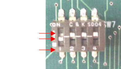
Note that there are four switches on the Dipswitch (SW7), numbered 1-4,
left to right. See chart below and Figure 7. Numbers are indicated on the
Dipswitch below the corresponding switch. The left switch (1) has a binary
value of eight; the next switch (2) has a binary value of four; the third
switch (3) has a value of two; the fourth switch (4) has a value of one. The
RF Channel then becomes the sum of the values of the various switches
in the down position. (If the switch is in the up position, its value is zero. If
the switch is down, its value corresponds with its binary value.)
VALUE 0 0 0 0 UP
VALUE 8 4 2 1 DOWN
SWITCH
1 2 3 4
For example, if RF Channel 8 is selected, the position of switch 1 is down;
the position of switch 2 is up; 3 is up; 4 is up.
Note: The configurations for Channels 0 and 1 will both select Channel 1.
10
Figure 7
Using an object with a fine point (a ballpoint pen or similar is adequate)
set the positions of the four switches for the desired RF Channel.
When the DCMI has power and the RF Channel has been set, the DCMI
is ready to enter Link Mode.
14. Link Mode
14.1 Linking
Linking is the process that ties a DCMI to an IRL by assigning a unique
address to the pair.
14.2 Link Process
Link Mode allows an IRL and a DCMI to link. When in Link Mode, the
DCMI is in its receive mode awaiting a link request from an IRL. The IRL
initiates linking by sending this first link request when the IRL Battery Pack
is connected. When a DCMI in the Link Mode receives a link request, the
DCMI automatically assigns an address randomly to itself and transmits it
to the IRL. When the two have the same address they are then linked
together. Since this address is unique to both components, other IRLs
and DCMIs are prevented from communicating with them.
Once the DCMI and the IRL are linked, The DCMI and the IRL then can
communicate using the assigned address.
14.3 How to put the DCMI into Link Mode
14.3.1 Verify that the DCMI is powered (CR 9 and CR6 are lit solid
green) and that the microprocessor is running (CR15 LED is
blinking green).
14.3.2 Once the RF Channel has been set (Section 13.2), press the
Tactile Switch (S1 for IRL A or S2 for IRL B).
14.3.3 The corresponding LEDs (CR9 for S1; CR6 for S2) will
alternately flash red and green. The DCMI is now in Link
Mode.
UP
DOWN
SWITCH #
11
The DCMI remains in Link Mode until it receives a link request from an IRL
or for thirty minutes, whichever comes first.
To abort Link Mode and return the DCMI to Standby, press the same
switch. Standby is indicated when the corresponding LED (CR9 or CR6)
blinks green.
When the DCMI is powered, the RF Channel is selected, and the
DCMI is in Link Mode, the system is ready for the IRL to initiate
linking.
15. IRL Linking to the DCMI via Battery Connection
15.1 Overview
When the battery pack is connected, the IRL will attempt up to three
transmissions to link properly. This process is made apparent by a series
of beeps and LED flashes from the IRL. See Section 18.
15.2 Connect the IRL Battery Pack to Initiate Linking to the DCMI
15.2.1 Verify the DCMI is in Link Mode (LED CR9 or CR6 flashes,
alternating red and green).
15.2.2 On the IRL, make sure the Battery Wire Harness is accessible
in the Battery Compartment. The Battery Wire Harness has
two, 2-position connectors at the end. (See Figure 3.)
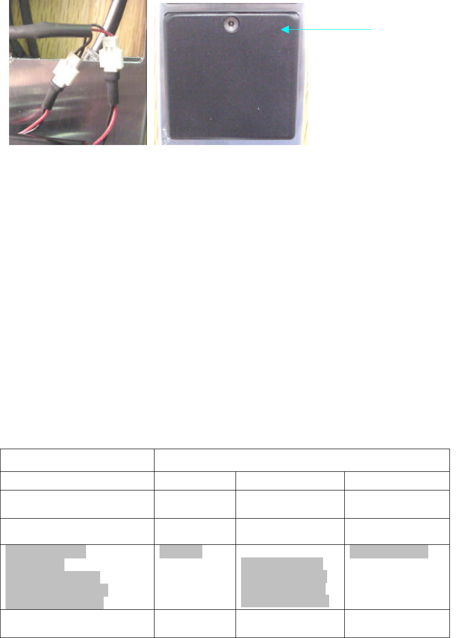
15.2.3 Connect the two connectors on the Battery Wire Harness to the
two connectors on the Battery Pack as shown in Fig. 8.
15.2.4 The IRL is now powered.
15.2.5 Once powered, the IRL initiates linking by transmitting a link
request.
15.2.6 When linking is completed successfully, CR9or CR6 turns solid
green.
15.2.7 The Battery Cover can be closed and secured with the Torx
screw. (See Figure 9.)
12
Figure 8 Figure 9
16. When and How to Change the RF Channel
The RF Channel may be changed for evaluation purposes or if the system
encounters interfering transmissions. When the system encounters interference
(most noticeably when the system attempts to link and cannot or Requests-to-
Enter fail), the RF Channel should be changed to alleviate this condition.
To change the RF Channel after the system is linked, the IRL battery must be
disconnected. Then the positions of the switches on the DCMI dipswitch (SW7)
should be changed to the new desired channel. Push the Link Mode Switch on
the DCMI. After reconnecting the battery pack, the IRL should be re-linked to the
DCMI on the new channel.
If the IRL and the DCMI do not re-link on the new frequency, the IRL will revert to
the RF Channel it was set at prior to disconnecting the Battery Pack.
17. Understanding the DCMI’s LED Indicators
Seven LED’s are on the PCB. They are CR15 Green, CR7 and CR10 Red, CR6
and CR9 both Green and Red.
Action DCMI LED
Indication
CR15 Grn CR7, 10 Red CR6, 9 Grn-Red
Normal, Micro P running,
Power applied Blinking Off Constant GRN
Micro P not running, Power
may be on or off Off Off Constant GRN
Trouble signal:
Low Battery
No Communication
Tamper, reader door
Tamper, DCMI door
Blinking
one blink, pause
two blinks, pause
three blinks, pause
four blinks, pause
Constant GRN
Link Mode Blinking Off Alternately flash
GRN/RED
Torx Screw

13
Transmitting a message Blinking Off 1 RED flash per
transmission
Receiving a message Blinking Off Blinks Off
momentarily
18. Understanding the IRL’s LED Indicators and Internal Sounder
The IRL LED is on the front of the Magstripe and Wiegand Reader housings (See
Figure 2) or on the top of the PROX housing.
18.1 Every time the battery packs are connected to the IRL, the IRL’s LED and
sounder indicate that it is powered. The red LED flashes once, followed
by multiple green LED flashes (four on the pre-production units) signifying
the software version and one red LED flash signifying the lock motor has
been driven to the locked position. This is accompanied by a beep.
18.2 When the IRL sends its first transmission (Link request), the LEDs indicate
this as well. The green LED flashes once followed by one red LED flash.
The LEDs flash in this sequence three times or until a link to a DCMI is
established whichever comes first.
18.3 When the IRL links successfully to a DCMI, the IRL indicates the RF
Channel on which it is linked. The green LED flashes and the Internal
Sounder beeps according to the RF Channel number. For example, if
linking has been successful on RF Channel 8, the green LED flashes and
the Internal Sounder beeps eight times.
18.4 If, after 3 transmissions, the IRL does not link to a DCMI, the red LED
flashes twice accompanied by a single long beep. The IRL reverts to its
previous channel and address before the power was disconnected.
See chart below for “card swiped & read”, “swiped and not read”, “door unlock/relock”
and “access denied” signals.
The following chart outlines the IRL LEDs and Internal Sounder indications.
Action LED Indication IRL Sounder Indication
1
IRL is powered 1 Red LED flash;
4 Green LED flashes;
1 Red LED flash
No beep
No beep
1 beep
2
IRL sends a link request (up
to 3 transmissions, until it is
linked)
1 Green LED flash;
1 Red LED flash
each of 3
transmissions
No beep

14
3
IRL linked successfully and
announces the RF Channel
on which it is linked
Green LED flashes
(number equal to the
RF Channel)
Beeps
(number equal to the RF
Channel)
4
IRL not linked successfully 2 Red LED flashes 1 long beep
Card swipe, not read None None
Card swiped and read None 1 beep
Followed by:
5
No communications 1 Red flash None
Door unlock 1 GRN flash None
Access denied 2 RED flashes 1 beep
Door relocks 1 RED flash 1 beep
Mag stripe, Wiegand and Prox readers will use the same LED/beep indicators.
19. Operating the Wyreless Access System
19.1 Overview
Once the IRL and the DCMI are linked, the Wireless Access system is
ready to be operated. A card swipe is required to operate the system.
When a card is swiped the IRL transmits a Request-to-Unlock.
A valid card must be used for a successful Request-to-Unlock. In Stand-
Alone Operation, a valid card is any magnetic stripe card with Track 2 data
(ATM cards, credit cards, etc.). In Panel-Connected Operation, a valid
card is a mag stripe card that has been validated by the access control
panel.
In Stand-Alone Operation, the DCMI receives this transmitted request and
will validate the card. Once validated, the DCMI will transmit a signal to
the IRL to unlock. The IRL will unlock and then relock.
In Panel-Connected Operation, the DCMI receives the transmitted
Request-to-Unlock from the IRL and then forwards the request to the
control panel. If the card used is validated, the control panel will signal
back to the DCMI a command to unlock. The DCMI then transmits the
unlock command to the IRL. The IRL will unlock and then re-lock.
19.2 Card Swiping
NOTE: One aspect of the Wyreless Access Pre-Production System that will
change in production units is the Magstripe reader. The Magstripe
reader head was inadvertently placed on the wrong side of the
Magstripe reader.
!
15
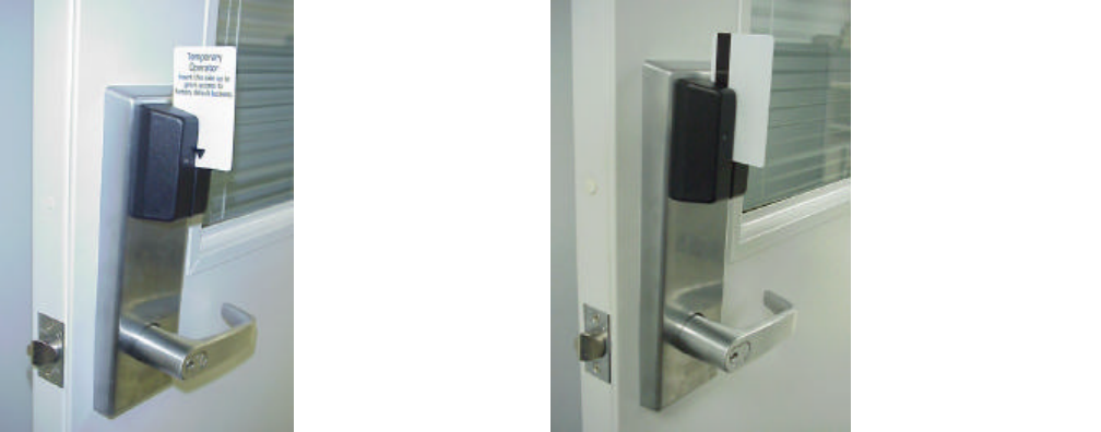
Cards need to be swiped in reverse. Normally, the front of the card
would face the left side (Figure 10) and the magnetic stripe would be read
on the right. But on this unit, cards should be swiped with the front of the
card facing the right and the magnetic stripe facing the left. (Figure 11.)
The reader head will be correctly oriented in the production version.
Insert the card with the magnetic stripe on the left (Figure 11) and then
slide it down keeping the back edge of the card firmly against the
back of the reader’s slot throughout the entire swipe.
Figure 10 Figure 11
19.3 Indications of a Successful Card Swipe
Whenever a card is swiped and at least 8 bits of information are read from
the card, a beep is sounded and the IRL transmits a Request to unlock.
A successful card swipe does not always result in an unlock. More than 8
bits are needed for a valid unlock request. So all required bits must be
read. A beep may be given because 8 bits are read, but more bits are
needed for an unlock.
If an invalid card is swiped correctly, the system will relay the information
but the door will remain locked.
19.4 Indication of an Unsuccessful Card Swipe
The best indication of an unsuccessful card swipe is when the IRL Internal
Sounder does not beep after a card swipe. Most likely, the card was
cocked or not swiped with its back edge against the reader slot back for
the entire swipe. It should be swiped again.
19.5 Indications of a Successful Request-to-Unlock (Card Swipe)
The indication of a successful Request-to-Unlock is when the IRL unlocks.
Mag stripe
Card must be
swiped in this
orientation
16
Approximately one second after a valid card swipe, the IRL green LED will
flash once and the IRL will unlock.
[Requests to unlock are .sent 3 times The DCMI LED, CR6 or CR9, indicates when it is
receiving the Request to unlock from the IRL by turning off momentarily (looks like a
flicker). The DCMI will transmit an acknowledgement to the IRL that it received the
transmission and sends the data to the panel. After that the IRL re-queries up to 5 times
to inquire if there is a response from the panel to unlock the door. Once the DCMI
receives a response from the panel it transmits it back to the IRL in response to one of
the IRL re-queries. The DCMI LED will flash red once for every time it sends a response
to the IRL then reverts to solid green. The IRL transmits its request up to three times or
until it is validated by the panel.]
Relock
Relock time is configurable from 1 to 255 seconds. After the preset time
has elapsed, the IRL relocks and the red LED will flash once and the
Internal Sounder will beep once.
19.6 Indications of an Unsuccessful Request-to-Unlock (Card Swipe)
The best indication of an unsuccessful Request-to-Unlock is when the IRL
remains locked. However, the IRL LED and Internal Sounder also
indicates an unsuccessful Request-to-Unlock. After an invalid card swipe
(unsuccessful Request-to-Unlock), the IRL red LED flashes twice and the
Internal Sounder beeps once. The IRL remains locked.
In Panel-Connected Operation, after an unsuccessful Request-to-Unlock,
the panel should indicate one of two reasons why the request was
unsuccessful. One is a Denied Request where the card used was a
recognized card but without the authority to unlock the specific door or
without the authority to unlock the specific door at that specific time. The
other is an Unrecognized Card where the card used was an invalid and
unrecognizable card (i.e., not part of the system).
20. Other Software Features
• Senses and reports door position to the panel.
• Periodically reports to panel for “Housekeeping” updates – ¼, ½, 1, 2, 5 or
15 minutes intervals, configurable. Battery life is a function of this time
period and number of card swipes. Request-to-Exit.

17
Battery Life Table
10 min.
5 min.
10 min.
2 min.
5 min.
5 min.
15 min.
¾ min.
1.0 min.
0 10,000 20,000 30,000 40,000 50,000
21. Pre-Production System Limitations
The pre-production system of Engineering Pilot Run units provides an early
assessment of performance capabilities. The following is an outline of limitations
of the pre-production system. These will be available in production.
• FCC – Does not have FCC approval.
• UL – Does not have UL approval.
• Shock and Vibration – Shock and vibration tests have not been completed.
• Link Mode Attenuated by 3dB – Feature has not been implemented.
• Low Battery Indication at the Panel – Feature has not been implemented.
• Internal Cache Memory – Feature is not implemented.
• IRL Reader Tamper Switch – Feature has not been implemented.
• DCMI Tamper Switch – Feature has not been implemented.
• RS 485 Communication Protocol to the Panel – Scheduled for Release 2.
22. Care and Usage
• Always operate the Wyreless Access Pre-Production System within
instructions and specifications described in this manual.
• Keep the DCMI door and IRL battery compartment closed when in use.
• Do not use the system outdoors.
• Do not paint any part, especially the DCMI antenna or IRL Antenna Cover.
23. Specifications:
23.1 Both Components
23.1.1 Temperature -10C to +60C
23.1.2 Humidity 20% RH to 95% RH, non-condensing
23.2 IRL
23.2.1 Voltage 4.75 – 13.2 VDC
23.2.2 Slam 10,000 cycles, 20 to 30 G per ANSI/BHMA
A156.25, section 6.3.5.1
23.2.3 Door Slam 10 cycles, 1000G minimum.
23.3 DCMI
23.3.1 Voltage 12VDC +10%, - 15%
23.3.2 Current 250 ma rms max.
Years
4
3
2
1
0

18
24. Troubleshooting
The following chart outlines several symptoms and their common fix. If, after
going through these instructions, the system is still experiencing difficulties, do
not attempt to fix. Contact Eric Gonzales at 630-762-4462 or Larry Brooks at 630-762-4471.
Symptom Cause Action
The LED CR15 is not blinking
and CR9 & CR6 do not illuminate
solid green when power is
supplied to the DCMI.
Power has not
been supplied
correctly or the
microprocessor is
not functioning.
Check the polarity of the panel
supply. If wrong the fuse must
be replaced. Replace with a
3/8 A, 250V, 2AG, fast acting
fuse.
The polarity of the panel power
supply is correct and the
symptom persists.
See above. Check the voltage. The
voltage must be between 5.0
and 12.0 VDC. Do not exceed
13.2 volts.
DCMI Symptoms
The voltage is at or fewer than
13.2 volts and the symptom
persists.
See above. Contact Eric Gonzales at 630-
762-4462 or Larry Brooks at
630-762-4471.
The IRL LEDs do not flash and
the Internal Sounder does not
beep when power is applied to
the IRL.
The battery pack is
not supplying
power to the IRL.
Check that the battery pack is
new and has been connected
properly.
The battery pack is good and has
been connected properly and the
symptom persists.
See above. Contact Eric Gonzales at 630-
762-4462 or Larry Brooks at
630-762-4471.
The IRL LEDS do not flash and
the Internal Sounder does not
beep to announce the RF
Channel when attempting to link.
The system is not
linking properly. Check that the DCMI is
properly in Link Mode before
power is supplied to the IRL.
The DCMI is properly in Link
Mode and the symptom persists. See above. Contact Eric Gonzales at 630-
762-4462 or Larry Brooks at
630-762-4471.
The IRL does not unlock after a
card swipe. The IRL and the
DCMI are not
communicating
properly.
A valid card is used and the
symptom persists. See above. If in Stand-Alone Operation,
check that the terminal block
has been attached properly. If
in Panel-Connected
Operation, check that the
wiring to the panel is correct.
IRL Symptoms
The card is valid and the terminal
block is attached properly or
panel connection is correct and
the symptom persists.
See above. Contact Eric Gonzales at 630-
762-4462 or Larry Brooks at
630-762-4471.
19
25. Other Installation Requirements
The DCMI must be installed by qualified professional or contractors in
accordance with FCC Part 15.203 indicated below.
Code of Federal Regulations
Title 47 – Telecommunications
Part 15.203 Antenna Requirement
An intentional radiator shall be designed to ensure that no antenna other than
that furnished by the responsible party shall be used with the device. The use of
a permanently attached antenna or of an antenna that uses a unique coupling to
the intentional radiator shall be considered sufficient to comply with the
provisions of this section. The manufacturer may design the unit so that a
broken antenna can be replaced by the user, but the use of a standard antenna
jack or electrical connector is prohibited. This requirement does not apply to
carrier current devices or to devices operated under the provisions of Sec.
15.211, Sec. 15.213, Sec. 15.217, Sec. 15.219, or Sec. 15.221.
Further, this requirement does not apply to intentional radiators that must be
professionally installed, such as perimeter protection systems and some field
disturbance sensors, or to other intentional radiators which, in accordance with
Sec. 15.31(d), must be measured at the installation site. However, the installer
shall be responsible for ensuring that the proper antenna is employed so that the
limits in this part are not exceeded.