Rentokil Initial 1927 plc GSD-500349 LongReach Radio Module User Manual Title page image
Rentokil Initial 1927 plc LongReach Radio Module Title page image
UserManual.wiki
>
Rentokil Initial 1927 plc
>
GSD-500349 User Manual
>
User Manual
Contents
1.
Users Manual - Control Panel
2.
Users Manual - AutoGate Connect
3.
Users Manual - Connect Radar
4.
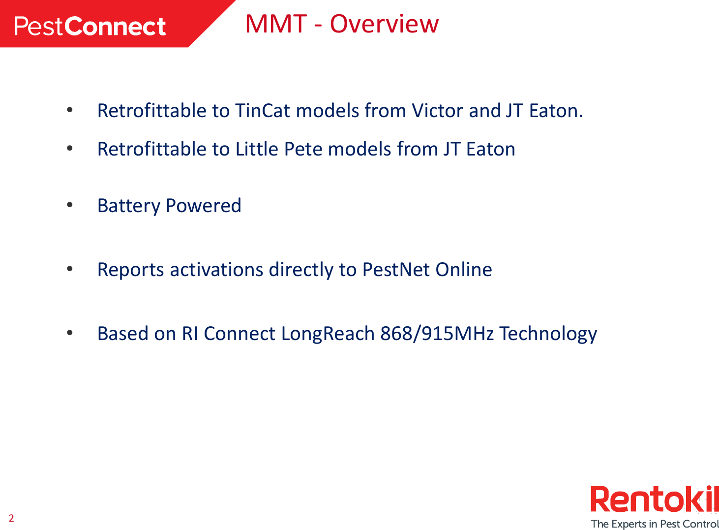
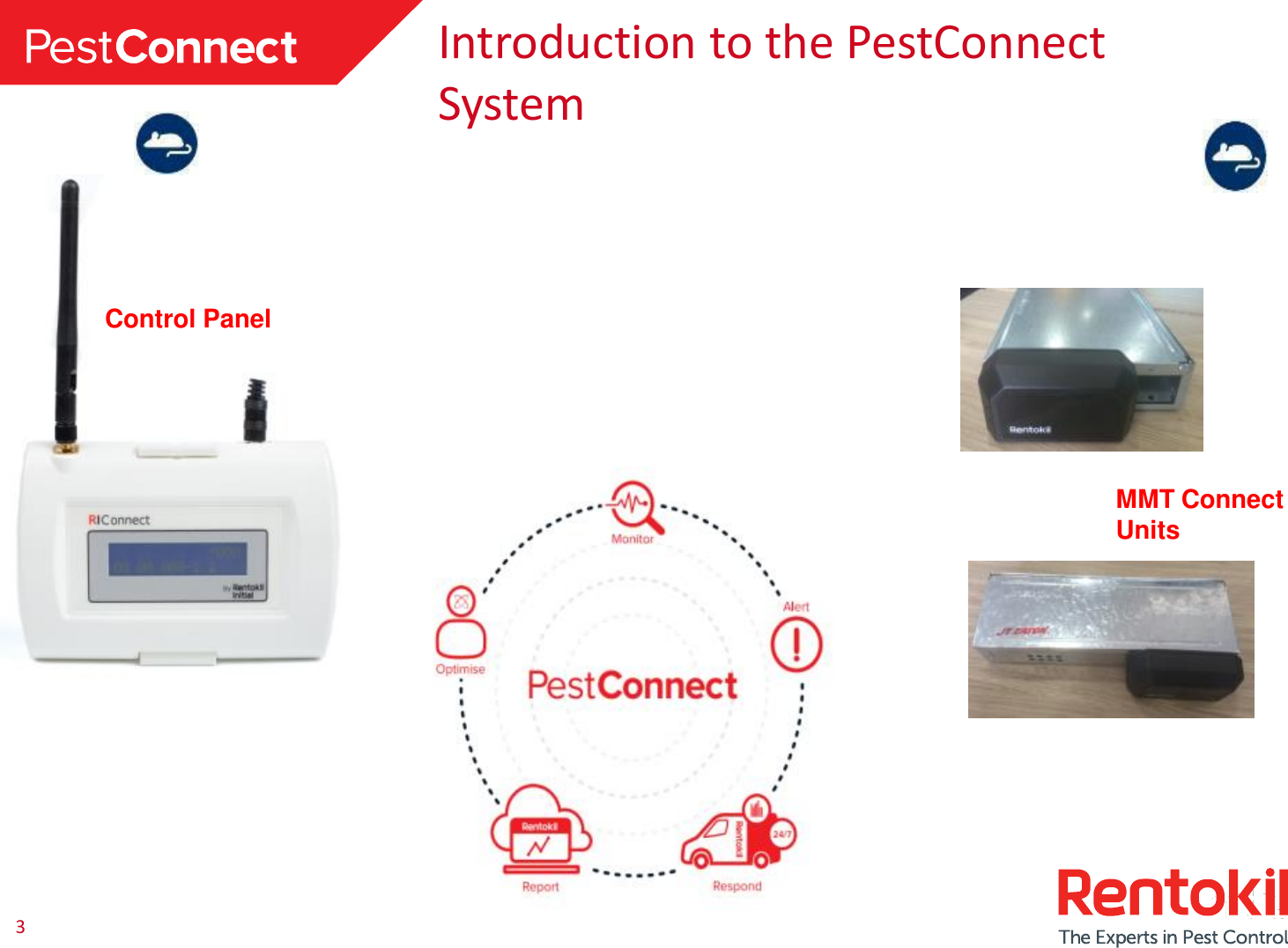
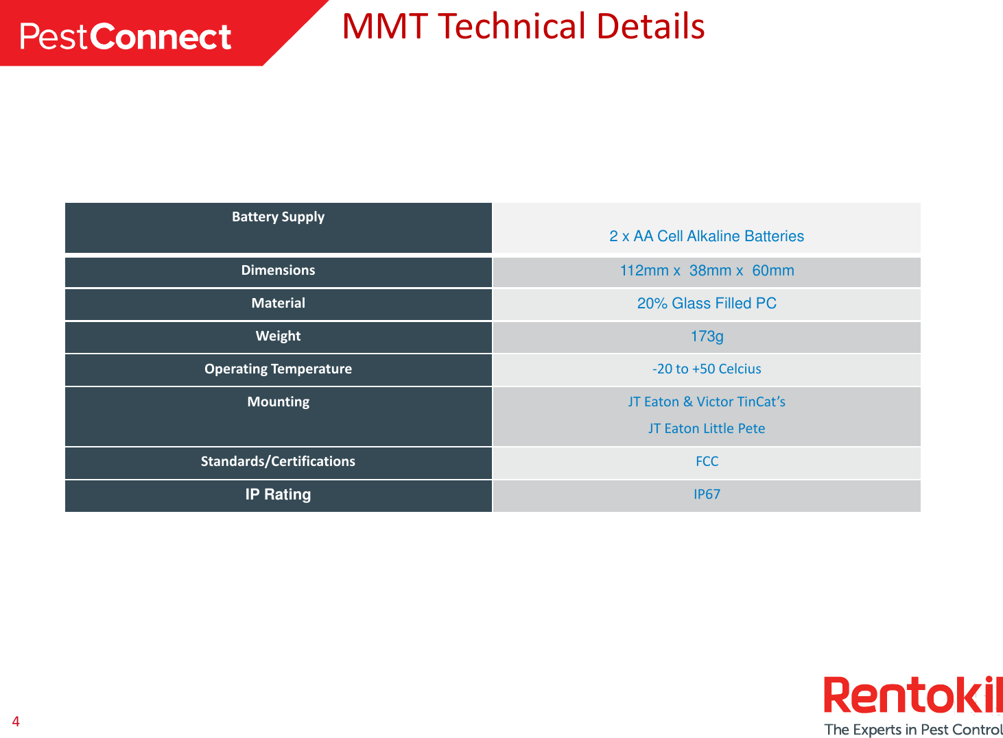
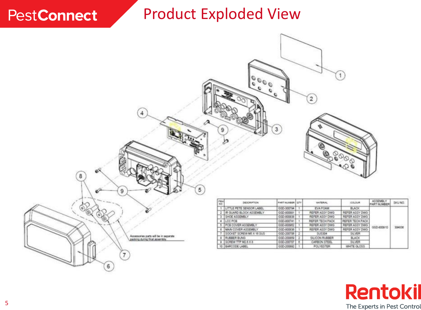
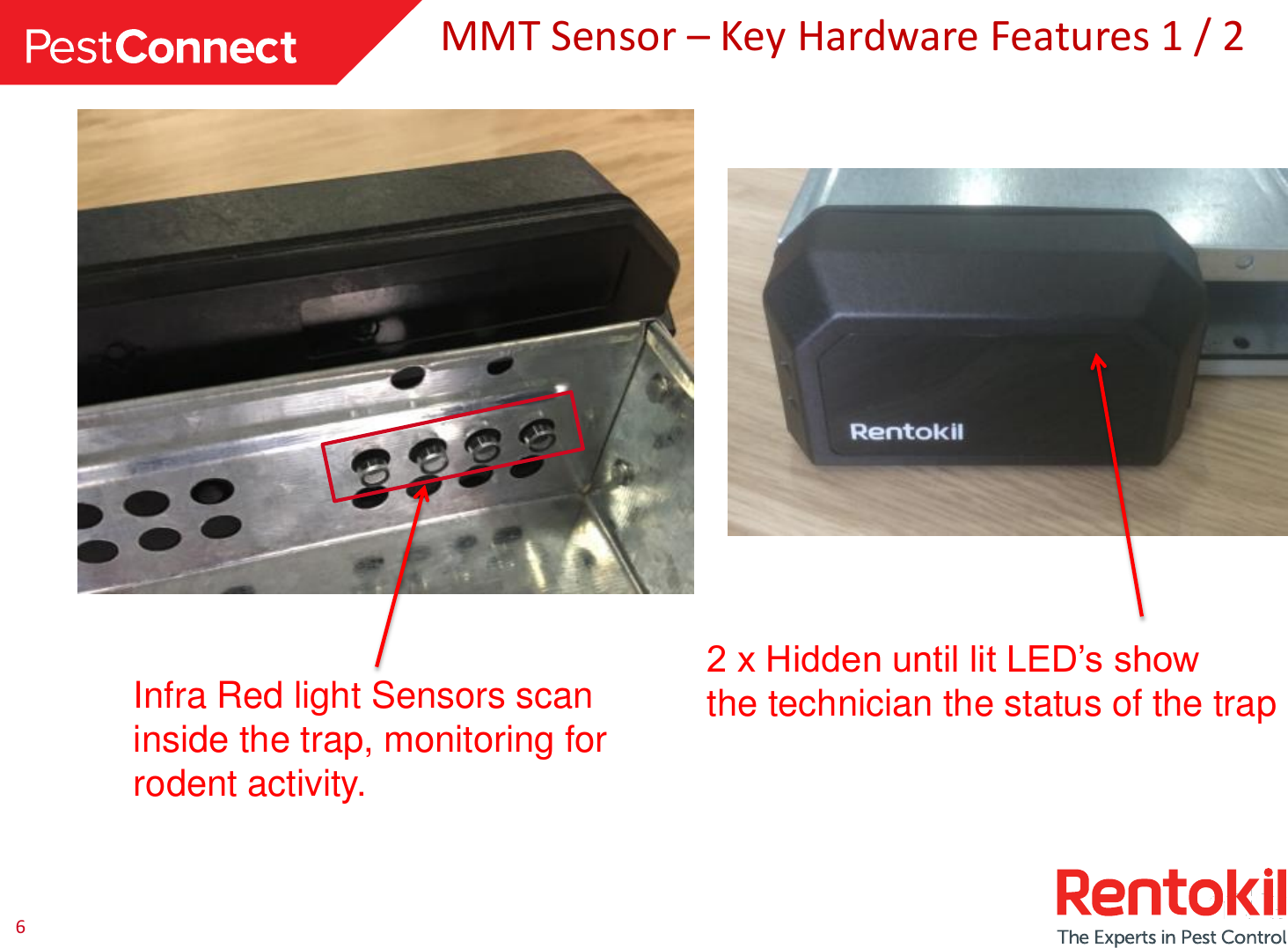
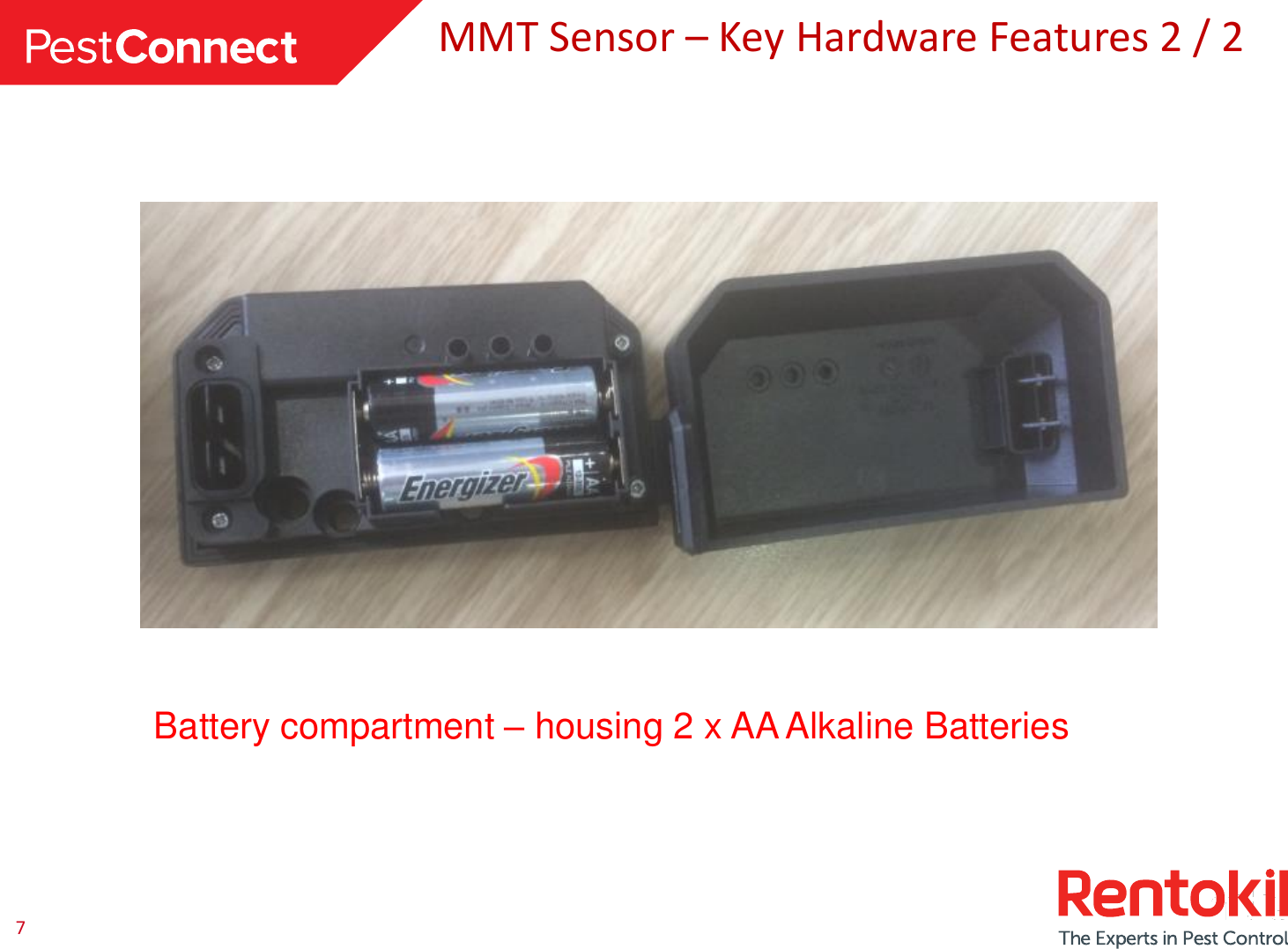
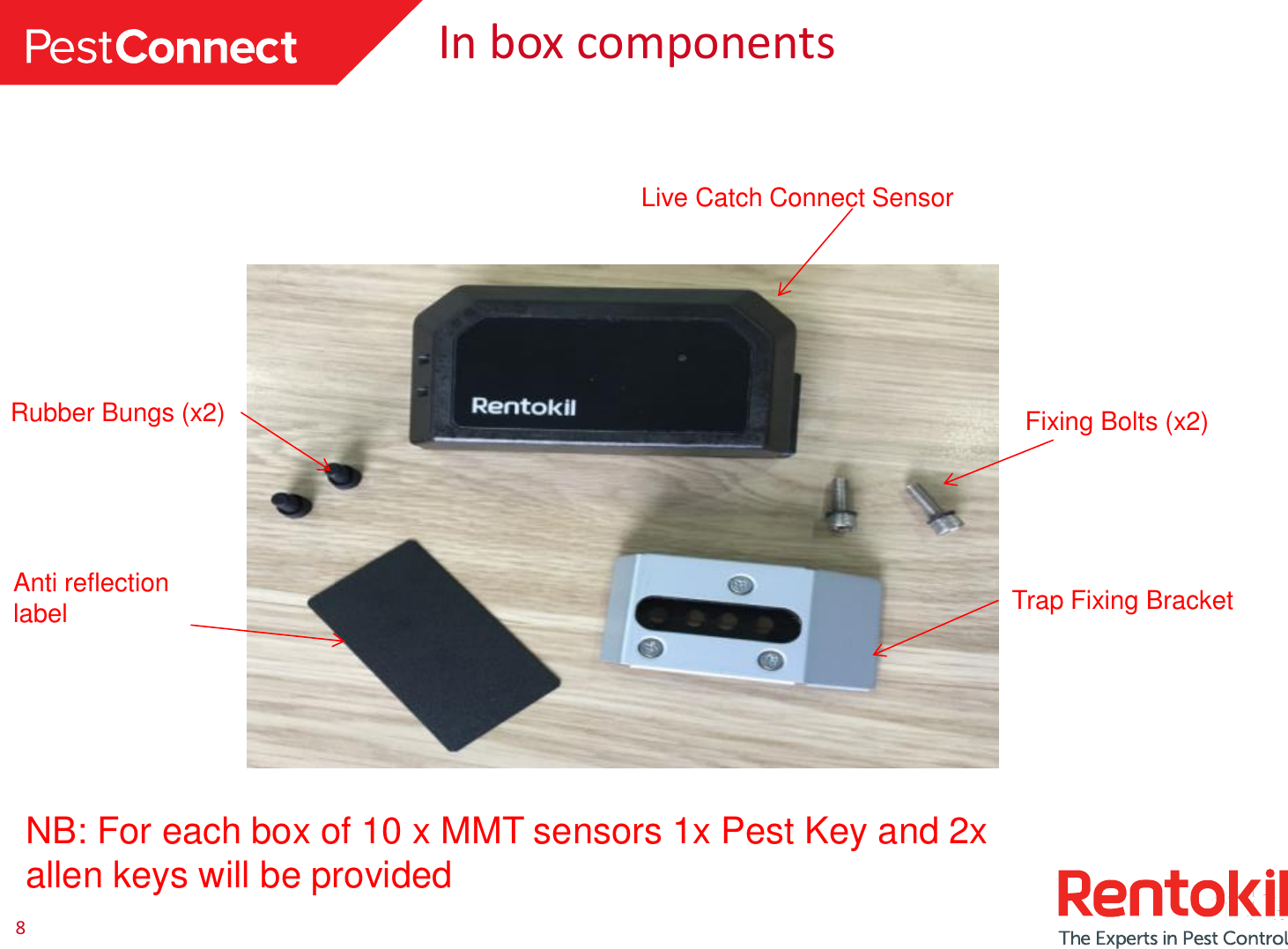
Users Manual - MMT
5.
User Manual
6.
User manual
User Manual
Navigation menu
Upload a User Manual
Namespaces
Wiki Guide
HTML
PDF
Info
Views
User Manual
Discussion / Help
Navigation