Rentokil Initial 1927 plc GSD-500349 LongReach Radio Module User Manual Connect Radar
Rentokil Initial 1927 plc LongReach Radio Module Users Manual Connect Radar
Contents
- 1. Users Manual - Control Panel
- 2. Users Manual - AutoGate Connect
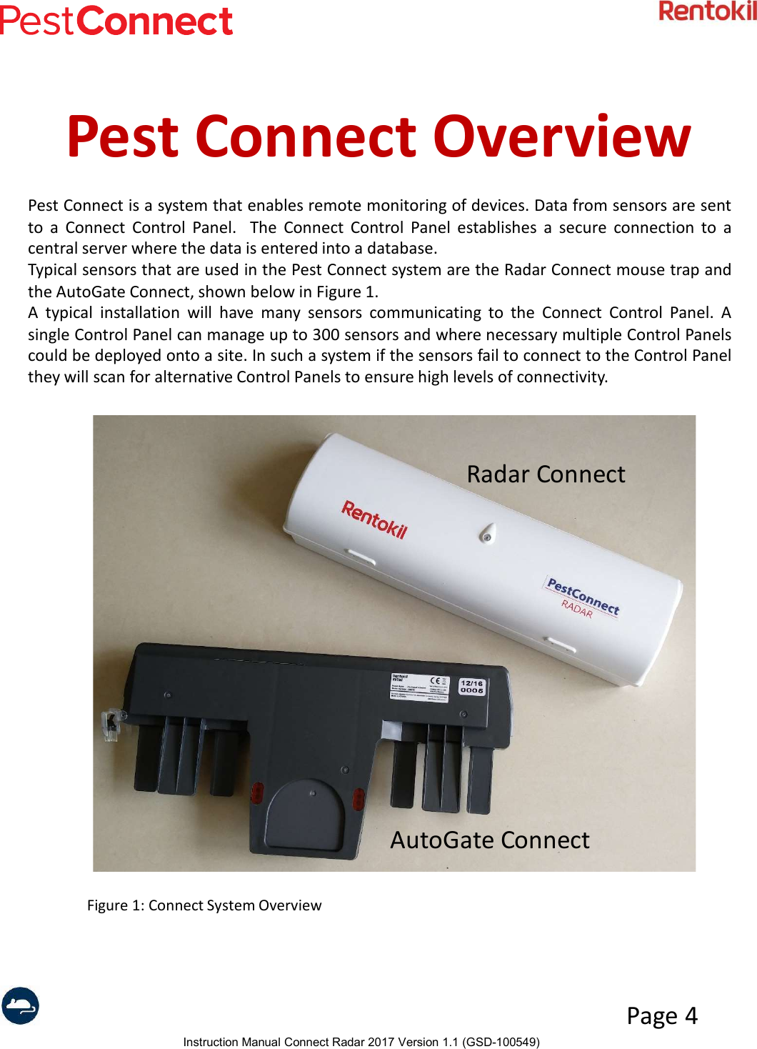
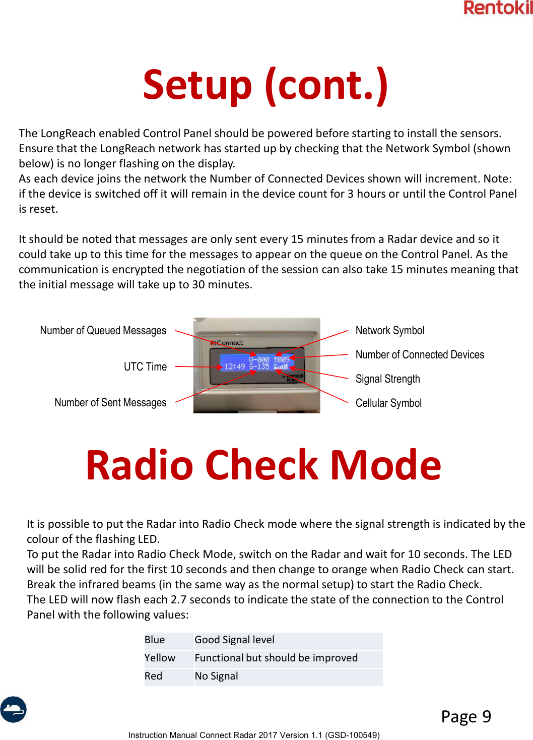
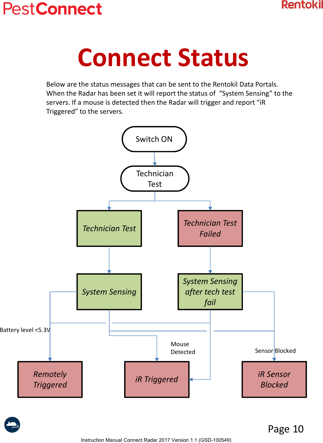
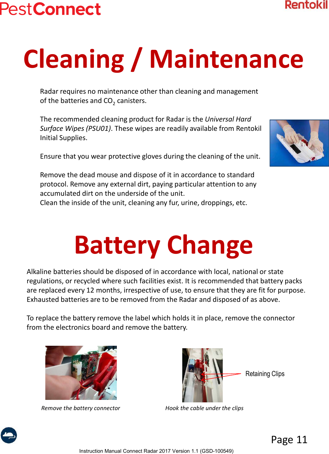
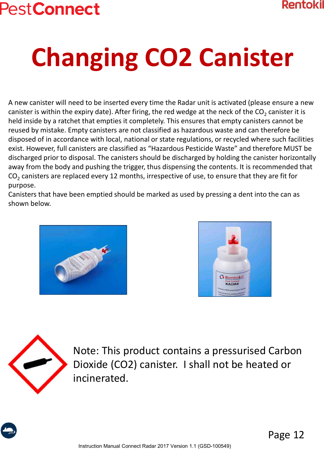
- 3. Users Manual - Connect Radar
- 4. Users Manual - MMT
- 5. User Manual
- 6. User manual
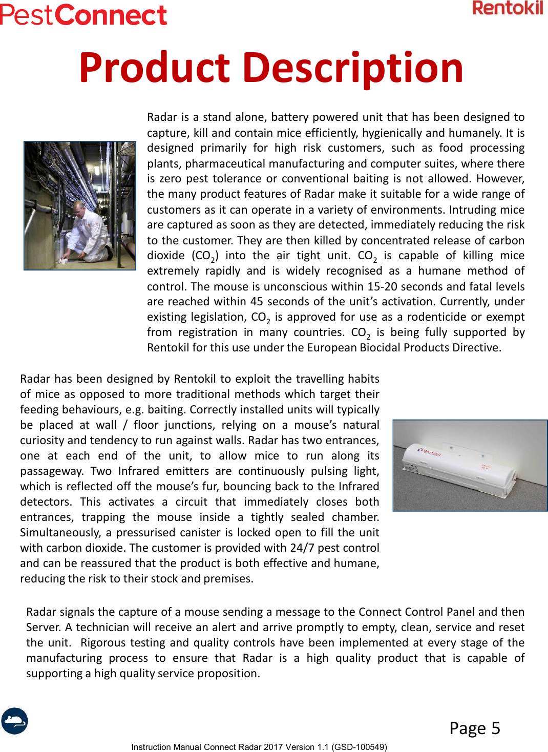
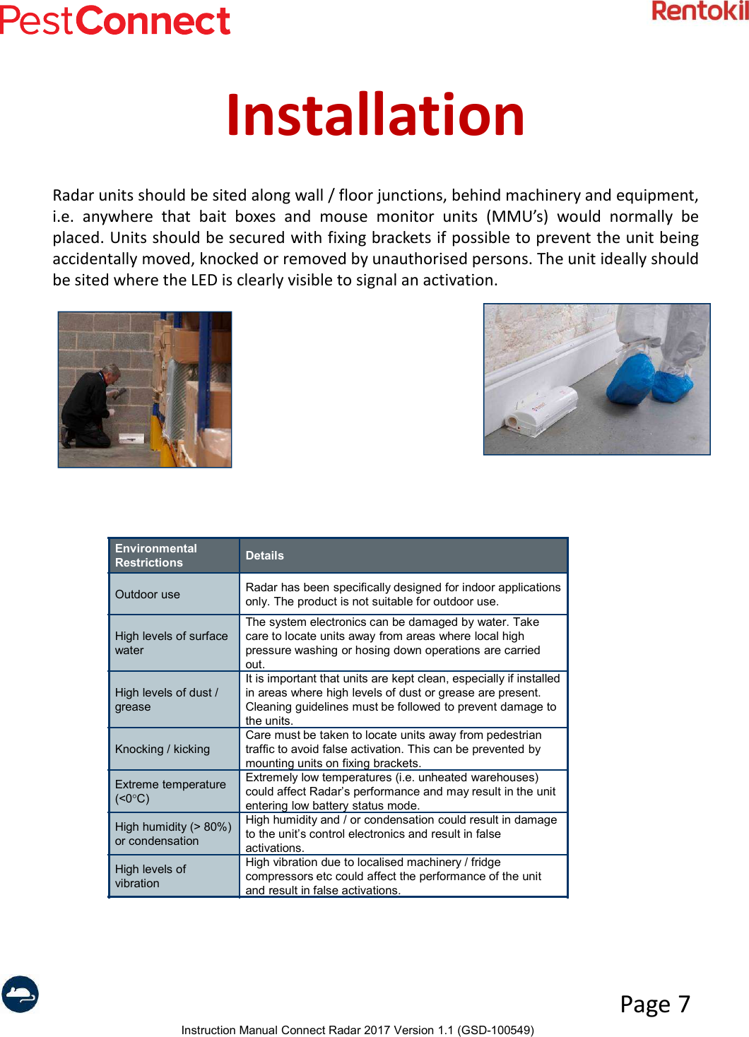
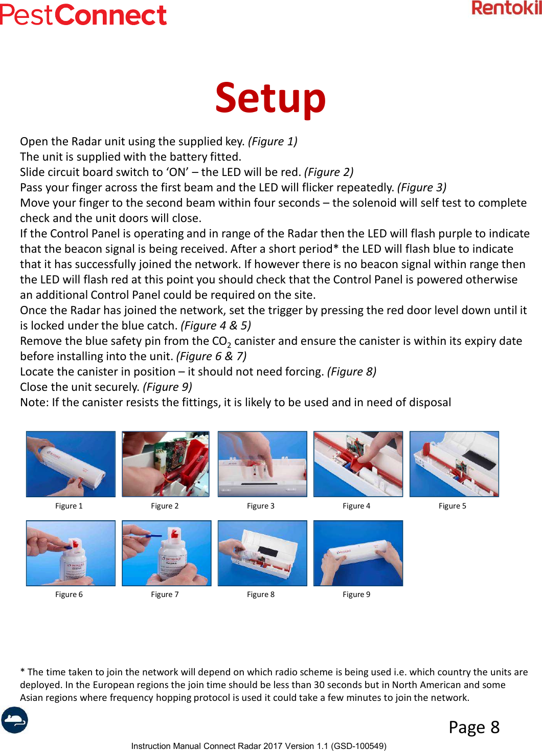
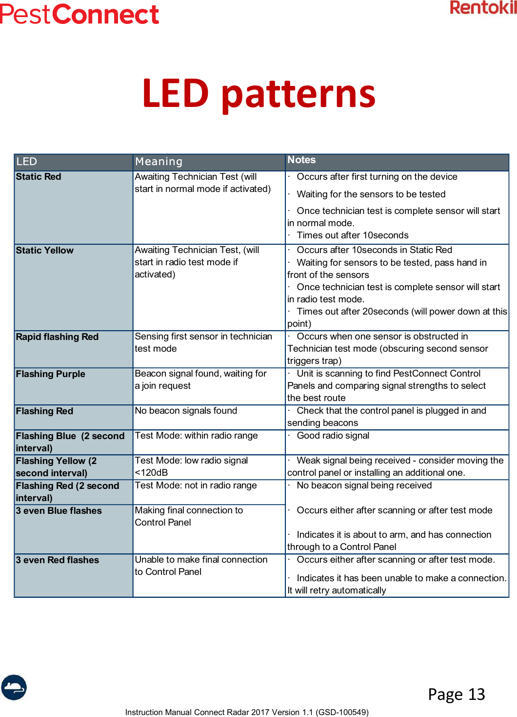
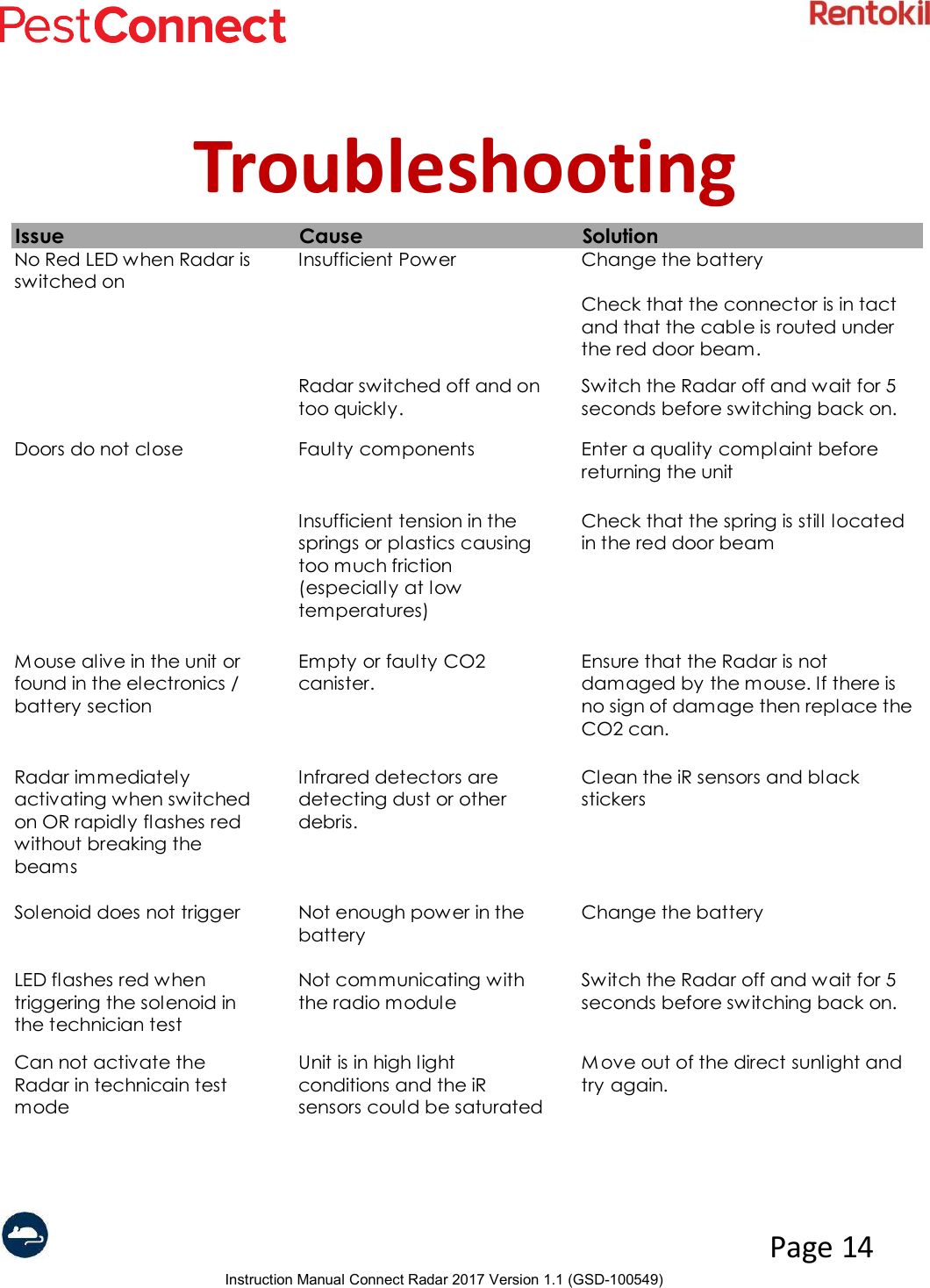
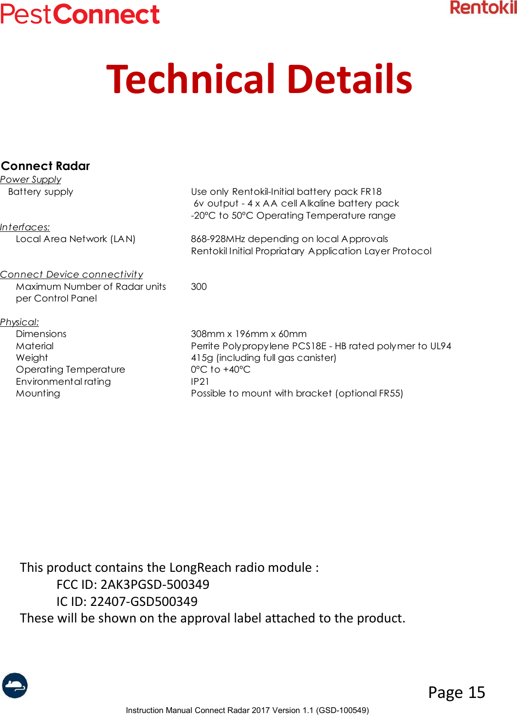
Users Manual - Connect Radar
![Instruction Manual Connect Radar 2017 Version 1.1 (GSD-100549)Page 16Item Description Part Number1 Main casing 3061282 Lever - [Red] 3601023 Lever spring 3601064 Trigger - [Blue] 3601035 Door beam 3601016 Door beam spring 3601059 Lens 21620710 Circuit board assy GSD-80073111 Radar LR Connect Approval Label GSD-20077612 Sensor label - Black 8567013 Battery pack 18033814 LR Radar Antenna Support GSD-30081415 Sensor label - Black 85670SAMPLE LABEL](https://usermanual.wiki/Rentokil-Initial-1927-plc/GSD-500349.Users-Manual-Connect-Radar/User-Guide-3834736-Page-16.png)