Restorative Therapies RT300-S Custom Controller w/Ipaq hx2100 PDA & Daughter PCB User Manual LB100108 RT300
Restorative Therapies Inc Custom Controller w/Ipaq hx2100 PDA & Daughter PCB LB100108 RT300
Contents
- 1. Users Manual 1 of 2
- 2. Users Manual 2 of 2
Users Manual 2 of 2

Fitting the equipment
26 • RT300-S User Manual 2005 Restorative Therapies Inc
Fitting the equipment
Using Surface Electrodes
The RT300-S System provides stimulation through adhesive surface electrodes placed on the skin over
the following muscle groups:
• right and left gluteals
• right and left hamstrings
• right and left quadriceps
Your clinician will advise you on which size electrodes are most suitable for you.
Before you fit the surface electrodes to your body, you must read the Warnings, Precautions and Safety
Measures section at the front of this guide. Also read the following sections – Surface Electrode Placement
Precautions and Caring for Surface Electrodes.
Surface Electrode Placement Precautions
• If there is poor contact between your skin and an electrode, or an electrode does not adhere to your
skin, you may need to trim hair from the electrode site. It is recommended you clip, not shave, the
hair.
• Following each session, always check electrode sites for any redness or other adverse reactions. If
your skin becomes irritated, move the electrode to a slightly different area until the irritation clears.
If irritation persists, or you experience a burn, contact your clinician.
• Do not use any surface electrodes that are smaller than those provided with the RT300-S System.
• Renew electrodes after 10-15 uses. See page 13 for re-ordering information.
• Periodically check the electrodes are in full contact with your skin. If an electrode repeatedly fails to
adhere properly, replace it with a new one.
• Rough edges on a surface electrode may also cause electrical burns so replace the electrode if this
occurs.
• Be especially careful to check the condition of the electrodes that you use on your gluteal muscles as
these are subject to more wear.
Caring for Surface Electrodes
• Use the self-adhering surface electrodes supplied by Restorative Therapies Inc. See the details in
Table 3 for ordering new electrodes.
• A surface electrode is expected to last for 10 to 15 applications with normal use. Throw a surface
electrode away if it adheres poorly or shows signs of wear and tear (e.g. rough edges).
• Gently remove a surface electrode by lifting it from one corner. Do not pull on the connecting lead as
this may damage the connection.
• Replace surface electrodes on the plastic carriers when they are not in use.
See the surface electrode pack for more instructions on use, care and storage.

Fitting the equipment
2005 Restorative Therapies Inc RT300-S User Guide • 27
Fitting the Surface Electrodes
To use the RT300-S System, you must have all 12 surface electrodes correctly fitted to your body, as shown in
Figure 23.
To fit the surface electrodes:
1. Make sure the skin where the electrodes are to be placed is clean and dry. Remove any lotion with an
alcohol wipe.
2. Peel the plastic carrier off a pair of surface electrodes.
3. Place the two surface electrodes on your body at the correct location. (See Figure 23).
4. Apply light finger pressure to the entire surface of each surface electrode to make sure it is in full
contact with your skin.
5. Repeat steps 2 to 4 for the remaining five pairs of surface electrodes.
Fitting the equipment
28 • RT300-S User Manual 2005 Restorative Therapies Inc
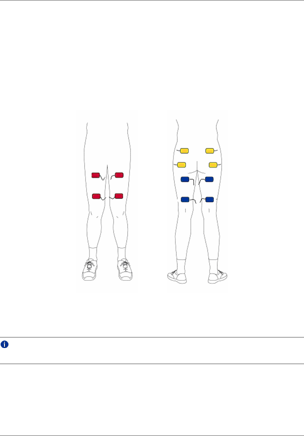
Where to Place Surface Electrodes
Figure 23 indicates the sites for electrode placement. However, as placement varies slightly between
individuals, your clinician will determine the locations that provide the most effective stimulation for you.
Quadriceps electrodes
(red channels)
Gluteal electrodes
(yellow channels)
Hamstrings electrodes
(blue channels)
Front view Rear view
Figure 23: Surface electrode sites
The Gluteal electrode leads should face outward (lateral). It is often easiest to attach the stimulation cable to the
Gluteal electrodes before placing them on your skin. All other electrode leads should face inwards (medial) as
shown in Figure 23.
Fitting the equipment
2005 Restorative Therapies Inc RT300-S User Guide • 29
Connecting the surface electrodes to the ergometer
Stimulation Cable Set
Once you have fitted the surface electrodes, connect them to the stimulation cable.
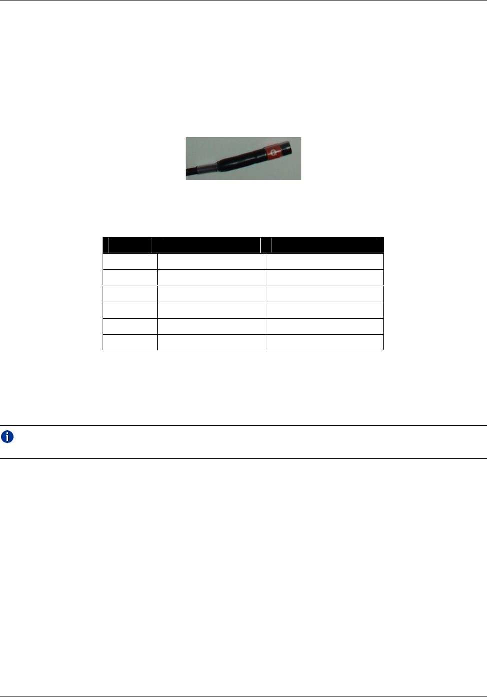
One end of the stimulation cable splits into 12 leads. Six leads for the left side of your body and 6 leads
for the right side. Each lead is color coded and labeled with two letters.
Figure 24: Color-coded, marked leads
Table 4 shows how the color and letters on a lead represents a particular muscle group.
Letters Color code Muscle Group
LG Yellow Left Gluteals
LH Blue Left Hamstrings
LQ Red Left Quadriceps
RG Yellow Right Gluteals
RH Blue Right Hamstrings
RQ Red Right Quadriceps
Table 4: Color-code/letter on stimulation cable leads
Each lead must be fitted to the corresponding surface electrode according to the color and letter.
Leads with an “R” on the label are for the right side of your body. Leads with an “L” on the label are for the left
side of your body.
Examples
A surface electrode fitted to your right quadriceps connects to a red lead marked RQ.
A surface electrode fitted to your left gluteals connects to a yellow lead marked LG.
Fitting the equipment
30 • RT300-S User Manual 2005 Restorative Therapies Inc
Connecting the Surface Electrodes
To connect the stimulation cables:
1. Using the color-coding and letters on each lead as a guide:
• connect the leads from the stimulation cable to the electrodes placed on your body.
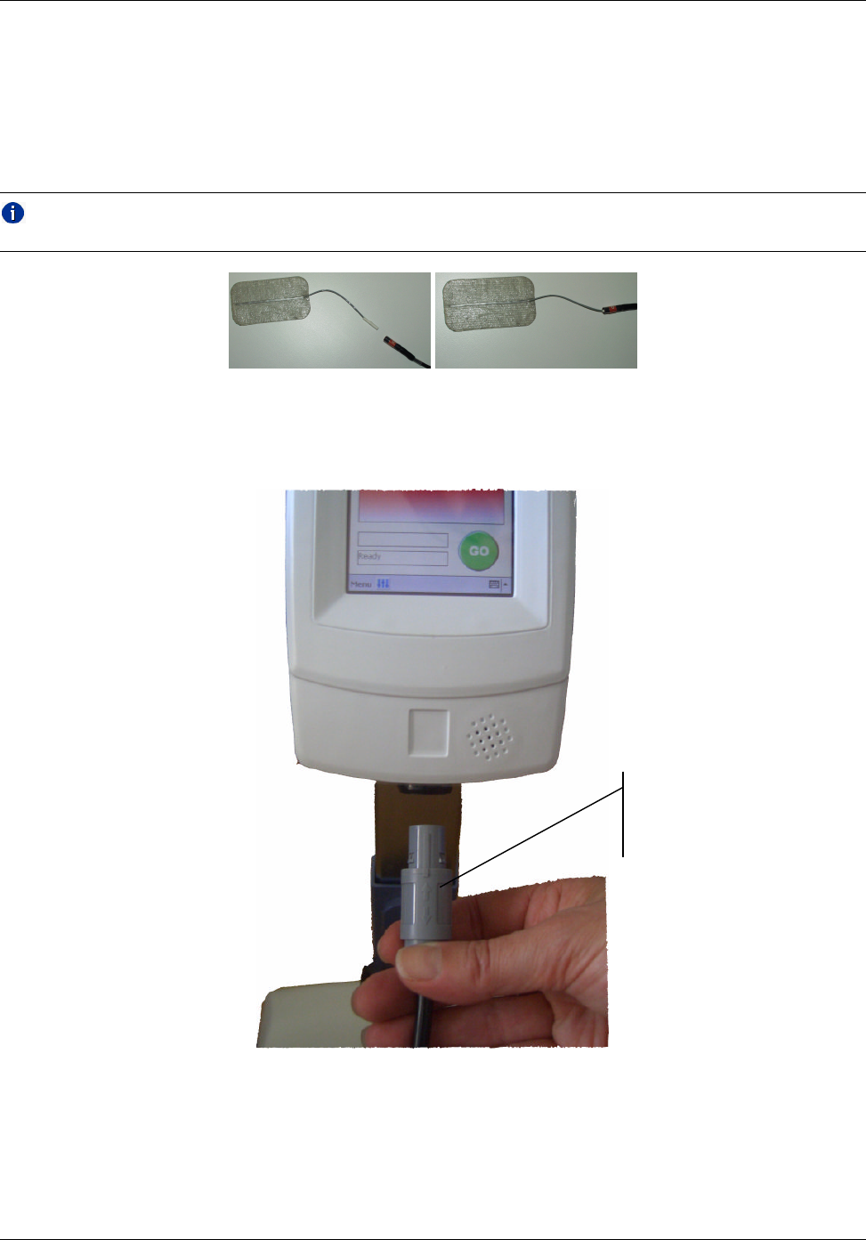
Make sure all lead pins are fully inserted (see Figure 25). Press your finger tip across the top of the socket to be
sure.
Figure 25: Connecting a lead to an electrode
2. Plug the stimulation cable into the outlet on the bottom of the Controller / stimulator – it will only fit
in one way (vertical arrow on the connector to the front) and it will click into place.
Figure 26 Attaching the stimulation cable
Vertical
arrows to
the front

Using the RT300-S System
2005 Restorative Therapies Inc RT300-S User Guide • 31
Using the RT300-S System
Using the RT300-S System involves:
• initial setup
• correctly positioning yourself on the ergometer and making any necessary adjustments
• fixing your feet in the footrests and your legs in the calf rests
• restraining your wheelchair so that it does not move during the therapy session
• understanding what happens during a typical therapy session
• understanding the functions of the RT300-S controller / stimulator
• starting and stopping a session
• knowing what happens if muscle spasm occurs
• being aware of the possibility of autonomic dysreflexia
Initial setup
When you first power on the RT300-S it is necessary to calibrate the Controller’s touch screen.
The procedure to do this is described below.
Once you have calibrated your controller’s touch screen you should leave the RT300-S connected to a power
outlet. This will ensure that the RT300-S controller’s back up battery remains charged.
If you disconnect your system from a power outlet you will need to repeat this calibration procedure.
Calibrate the touch screen
1. Follow the instructions provided by the Controller
• Using the Stylus touch the screen in the positions requested by the controller.
• Cut and paste the demonstration appointment
• Select your time zone
Using the RT300-S System
32 • RT300-S User Manual 2005 Restorative Therapies Inc
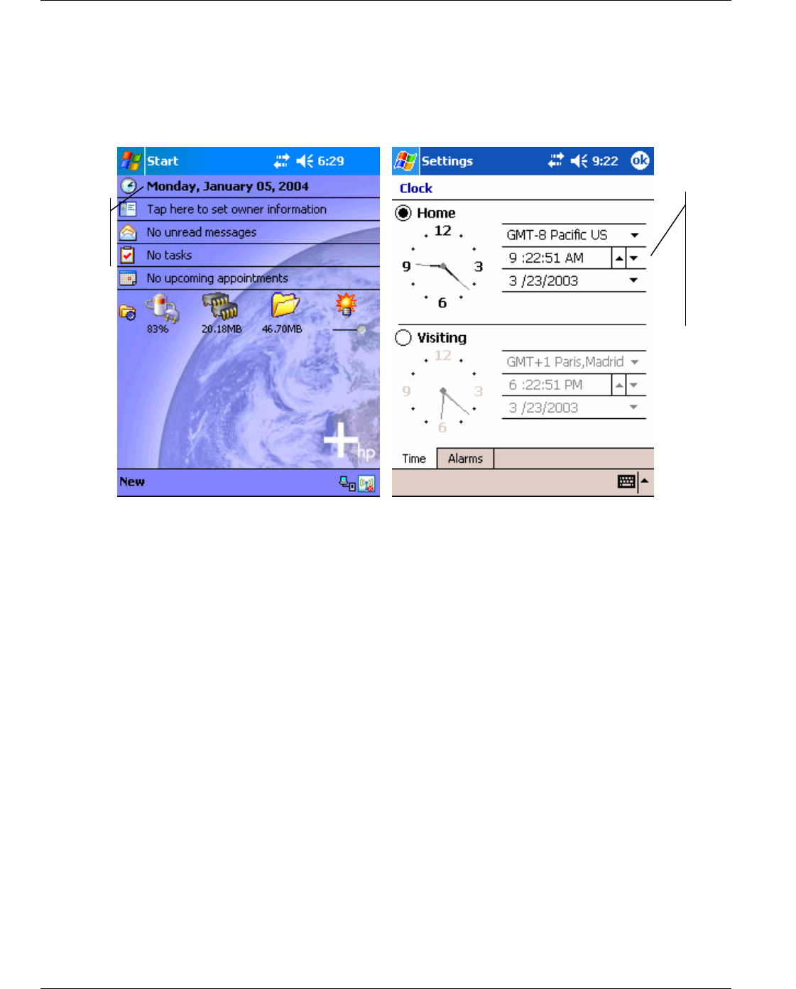
Set the time and date
1. Set the Home time on the system as shown below:
1. Press
the date 2. Enter
the
correct
time and
date
here
Using the RT300-S System
2005 Restorative Therapies Inc RT300-S User Guide • 33
Positioning on the Ergometer
Getting into the correct position on the ergometer involves:
• setting the distance between your wheelchair and the ergometer
• strapping your feet into the footrests and legs against the calf rests
Setting the distance
The distance you should set between your wheelchair and the ergometer is affected by:
• the type of wheelchair you use
• the length of your legs
• your height
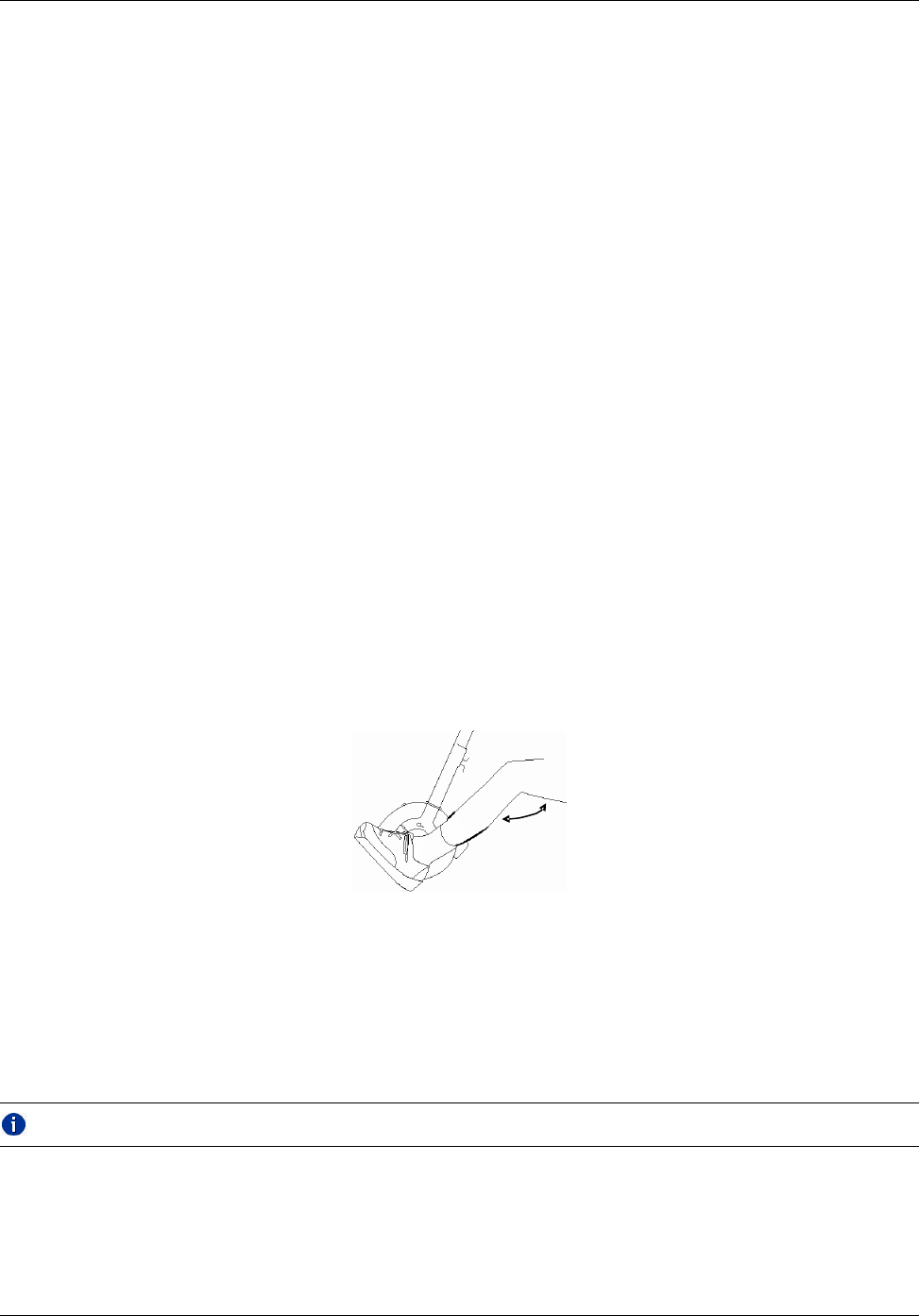
The most effective way to check you are correctly positioned is to check the angle of your knee joint when
your foot is in the footrest and your leg is fully extended.
To set the correct distance:
1. Place your foot in a footrest, resting your leg in the leg guide.
2. Move your wheelchair slowly back or forward until your knee joint reaches a 45° angle, as shown in
Figure 27.
Figure 27: Knee joint at 45° angle
Using the Calf Rests and Footrests
It is recommended you always wear shoes (e.g. running shoes) when using the RT300-S System. The
footrests are designed to accommodate shoes, while the calf rests help support the legs.
Both the footrests and calf rests have straps for added support and safety.
Do not put your whole body weight on the pedals when you place your feet in the footrests.
To use the footrests and calf rests:
1. Open the straps on the footrests and calf rests.
2. Place your left foot in the footrest, resting your leg against the leg guide.
45
°
angle
Using the RT300-S System
34 • RT300-S User Manual 2005 Restorative Therapies Inc
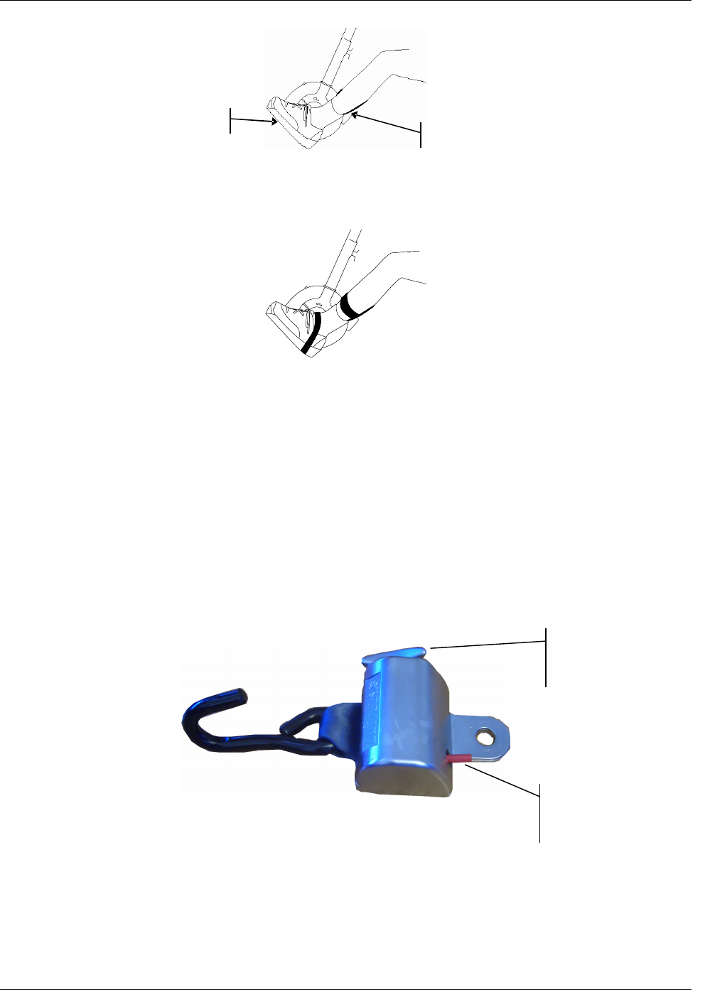
Figure 28: Foot and leg position
3. When you are correctly positioned, fasten the straps on the footrest and leg guide.
Figure 29: Straps fastened on footrest and leg guide
4. Repeat steps 2 and 3 for your right foot.
Using the wheelchair restraints
Once you have correctly positioned your wheelchair you should use the restraining straps provided to
ensure that your wheelchair does not move during your therapy session.
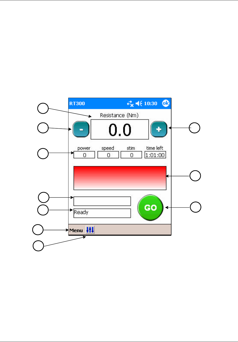
1. Hold down the red lever on the front of one of the restraining straps and pull out the strap
2. Hook the strap to a secure point on your wheelchair beneath the level of your seat.
3. If necessary turn the tightening knob to take up any slack
4. Repeat for the other restraining strap
Figure 30 Restraining strap
To remove the wheelchair restraint:
1. Hold down the red lever on the front of one of the restraining strap and pull out enough slack to allow
you to unhook the strap from your wheelchair
2. Release the strap and it will retract back into the restraint system.
leg guide
footrest
Hold down this
lever to free
the strap
Take up any slack
with tightening knob
Using the RT300-S System
2005 Restorative Therapies Inc RT300-S User Guide • 35
Using the Controller
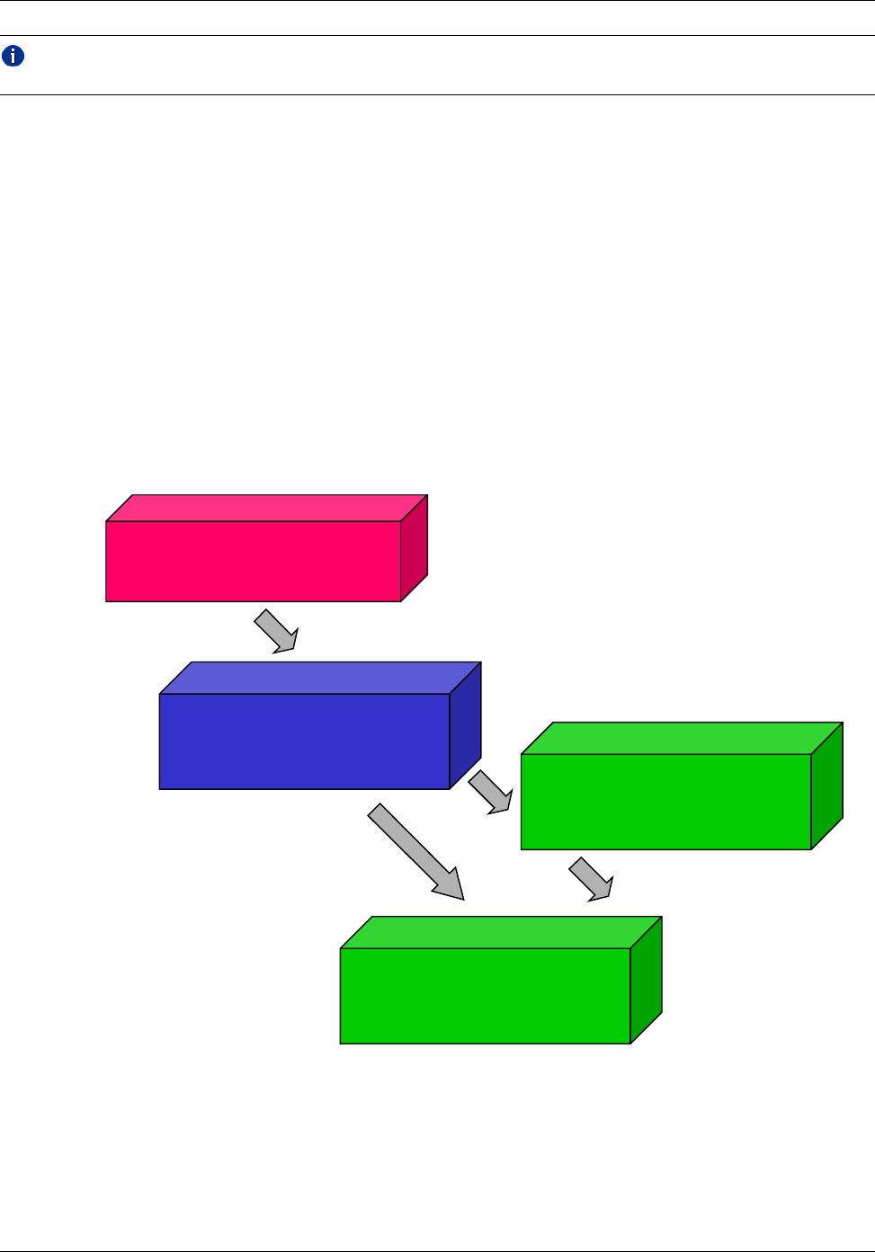
The controller’s Therapy Session screen shows what is happening at any particular time during a therapy
session. The controller’s touch-sensitive screen allows you to:
• Start and stop your therapy session
• Monitor the progress of your therapy session
• See any warnings or errors that occur
• Update your stimulation parameters
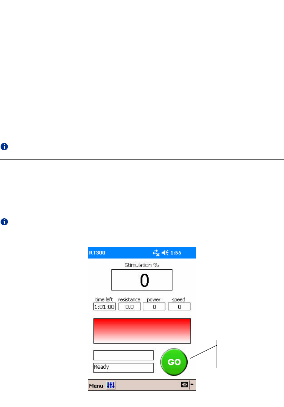
Figure 31: Controller - Therapy Session screen
1
2
3
5
8
6
4
7
9
10

Using the RT300-S System
36 • RT300-S User Manual 2005 Restorative Therapies Inc
Main display window shows one of:
Ø Time left
Ø Cycling speed
Ø Stimulation level (by default)
Ø Resistance
Ø Power
Tap this window to cycle the displayed data.
Decrease button
This button is only shown if Resistance is being displayed in the main display
window AND patient adjustment has been enabled by the Clinician (see note
below). Tap this button to reduce your resistance level during active therapy.
Increase button
This is only shown if Resistance is being displayed in the main display window
AND patient adjustment has been enabled by the Clinician (see note below).
Tap this button to increase your resistance level during active therapy.
Secondary display windows.
Tap these windows to transfer their data to the main display window.
Graphical display of data as your therapy session progresses
Ø The green tracing shows your stimulation level history
Ø The blue area represents time and stimulation level remaining
Notifies of a pending change in the phase of your therapy session (see page 37)
Therapy State:
Ø Ready
Ø Warm up (initial passive cycling)
Ø Active cycling (stimulation operating)
Ø Passive cycling (fatigue has been detected)
Ø Cool down
Ø Finished
Start and Stop button
“Start” when the system is stopped and “Stop” when the system is operating.
Ø Press “Start” to commence your therapy session.
Ø Press “Stop” if you want to stop your therapy session early.
Menu bar allows for
Ø About RT300… displays the version of the RT300 software
Ø Log in… allows your clinician to log in to the system to adjust therapy
parameters
Configuration button
See page 41 for how to adjust your stimulation settings
1
2
3
4
5
6
8
7
9
10
Using the RT300-S System
2005 Restorative Therapies Inc RT300-S User Guide • 37
Clinician note: To enable or disable patient control of resistance tap on “Resistance” and enter the Clinician code
when prompted.
Therapy Sessions
Once your are correctly positioned (page 33) and your wheelchair is restrained (page 34) you are ready
to begin a therapy session.
RT300-S System therapy sessions help you to pedal using your own muscle power, providing the
opportunity to make continual progress over the course of your therapy plan.
The RT300-S System is designed with pre-set (default) therapy settings. Your clinician may also make
adjustments to settings like the:
• length of your therapy session
• amount of power your muscles generate during a therapy session
How the therapy session progresses
Figure 32 Phases of your therapy session
Inbuilt Safety Measures
At the end of each session, the RT300-S System automatically switches off. There are also inbuilt safety
measures to help protect you during therapy. You should be aware that:
1. Warm up
The system’s motor moves your legs and
any initial muscle spasms are worked out
2. Active
Electrical stimulation evokes coordinated
muscle contractions so you cycle using your
own muscle power
3. Cool down
The system’s motor takes over allowing your
muscles to stop working while still moving
through range of motion.
2.b Passive
If muscle fatigue is detected, stimulation will
stop and the system’s motor will take over
for the remaining active therapy phase.
Using the RT300-S System
38 • RT300-S User Manual 2005 Restorative Therapies Inc
• if the system registers muscle fatigue, the ergometer’s motor takes over for the remainder of the
session. You will see that the display swaps from displaying “Active cycling” to “Passive cycling”.
• if an electrode falls off, the system immediately pauses by ceasing stimulation and switching off the
motor. An error message is displayed on the controller Therapy Session screen to let you know what
has happened. After you fix the problem, tap Go to restart the session.
Handling Muscle Spasm
At the beginning of the Warm Up phase, muscle spasms may occur. These usually subside before the
Warm Up period ends.
If the spasms persist, wait approximately 5 minutes and then begin the therapy session again. If the
spasms still do not subside, the therapy session should be postponed.
Starting and Stopping a Therapy Session
Before every therapy session, always empty your bladder to minimize the risk of autonomic dysreflexia occurring.
If you have any concerns, talk to your clinician.
Starting a Session
To start a therapy session:
1. If the screen is dark, touch the controller screen to turn the system on.
2. Tap Go. The ergometer starts operating and your therapy session begins.
Tapping…
You can tap the screen using the stylus provided or your fingernail. If your fingernails are short, simply use the
back of your finger to allow your fingernail to contact the screen.
Figure 33 Starting a session
Tap here to
start your
session
Using the RT300-S System
2005 Restorative Therapies Inc RT300-S User Guide • 39
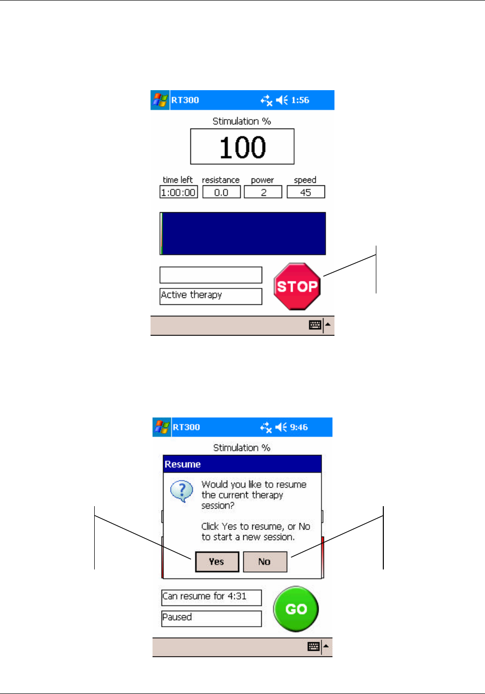
Stopping a Session Early
The RT300-S System automatically stops once the end of the session is reached. However, you can stop
the session at any time if you wish. To stop a therapy session early:
1. Tap Stop. The session is ended.
Figure 34 Stopping a session early
Restarting a Session
The RT300-S will give you the option of either restarting your session or commencing a new session if you
press GO within 5 minutes of stopping the session early.
Figure 35 Resume the session or restart ?
Tap here to
stop your
session
Tap NO if
you want to
restart with
a new
session
Tap YES if
you want to
resume
where you
left off
Using the RT300-S System
40 • RT300-S User Manual 2005 Restorative Therapies Inc
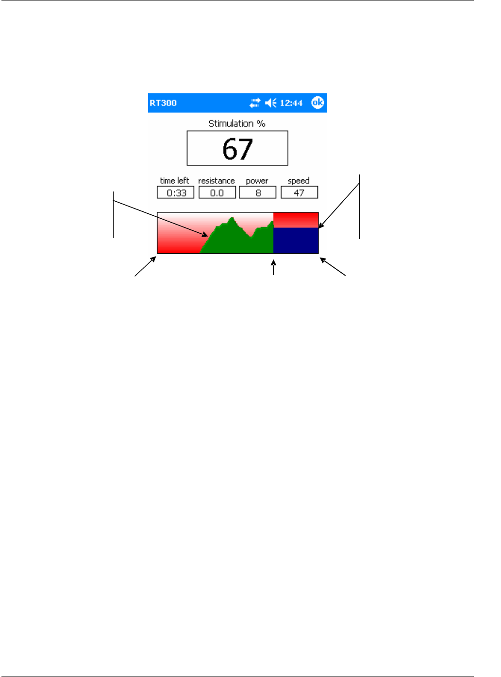
Data display graph
The figure below illustrates the meaning of the data display graph which shows you how your session is
progressing.
Figure 36 Data display
The green area is
the history of
your stimulation
The height of the blue
area represents your
current stimulation
percentage.
Start of
session
Now End of
session
Using the RT300-S System
2005 Restorative Therapies Inc RT300-S User Guide • 41
Adjusting parameters
Clinicians should be cautious in setting initial maximum stimulation levels. Children in particular may require
initial levels to be set lower than the default level.
You should only adjust these parameters after consulting with you clinician.
Stimulation parameters
The stimulation parameter page is accessed via button
Enter the password when prompted. This password can be requested from your Clinician; it is designed
to prevent unintended access to the stimulation parameters by children.
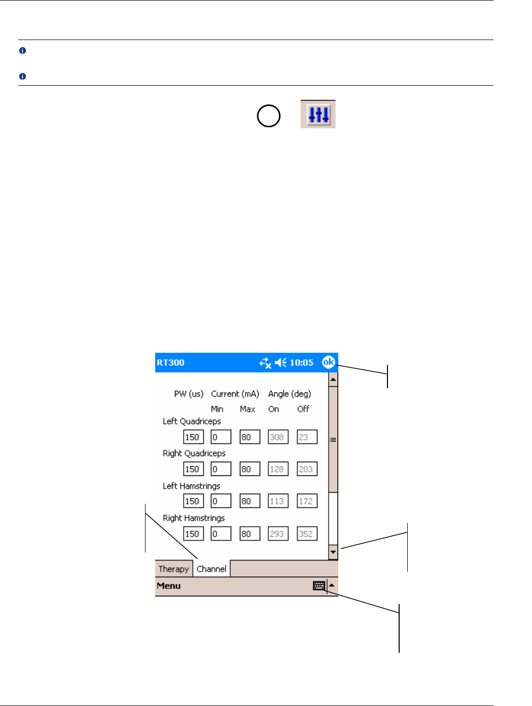
Select the Channel page by tapping on the Channel tab (see figure below).
This page allows you to change the pulse width, minimum current and maximum current that is delivered
by the RT300-S system to each of your muscle groups. This page will default to initial appropriate levels
depending on whether you have an adult or pediatric RT300-S system.
During active therapy the RT300-S system will use as much electrical stimulation as is required to keep
you cycling at the set cycling velocity. However, the stimulation amplitude on any channel will never
exceed the maximum (Max) that has been set for that channel (see Figure 37).
Normally, if sensation to stimulus is not an issue, the maximum (Max) stimulation levels should be left at
140 mA for adults or 80mA for children.
The minimum (Min) stimulation is the amplitude in milliamps (mA) where a muscle first begins to
contract as a result of surface electrical stimulation.
Figure 37 Stimulation parameter page
Making changes
To make a change to the stimulation parameters:
1. Tap the keyboard in the lower right corner of the screen
2. Highlight the number to be changed
3. Enter the new number using the displayed keyboard
4. Tap OK in the top right of the display
10
Tap the keyboard to
display the data entry
keyboard
Tap OK when done
Select the “Channel”
tab Scroll down to see the
Gluteal settings
Using the RT300-S System
42 • RT300-S User Manual 2005 Restorative Therapies Inc
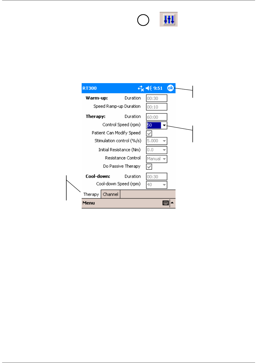
Therapy parameters
The stimulation parameter page is accessed via button
Enter the password when prompted. This password can be requested from your Clinician; it is designed
to prevent unintended access to the stimulation parameters by children.
Select the Therapy page by tapping on the Therapy tab (see figure below).
This page allows you to change one or more therapy parameters if enabled by your Clinician.
Figure 38 Therapy parameter page
Making changes
To make a change to the cycling speed:
1. Tap the keyboard arrow to the right of the speed selection box
2. Tap the required new speed setting
3. Tap OK
10
Tap OK when done
Select the “Therapy”
tab
Tap the arrow and
select the new speed
Using the RT300-S System
2005 Restorative Therapies Inc RT300-S User Guide • 43
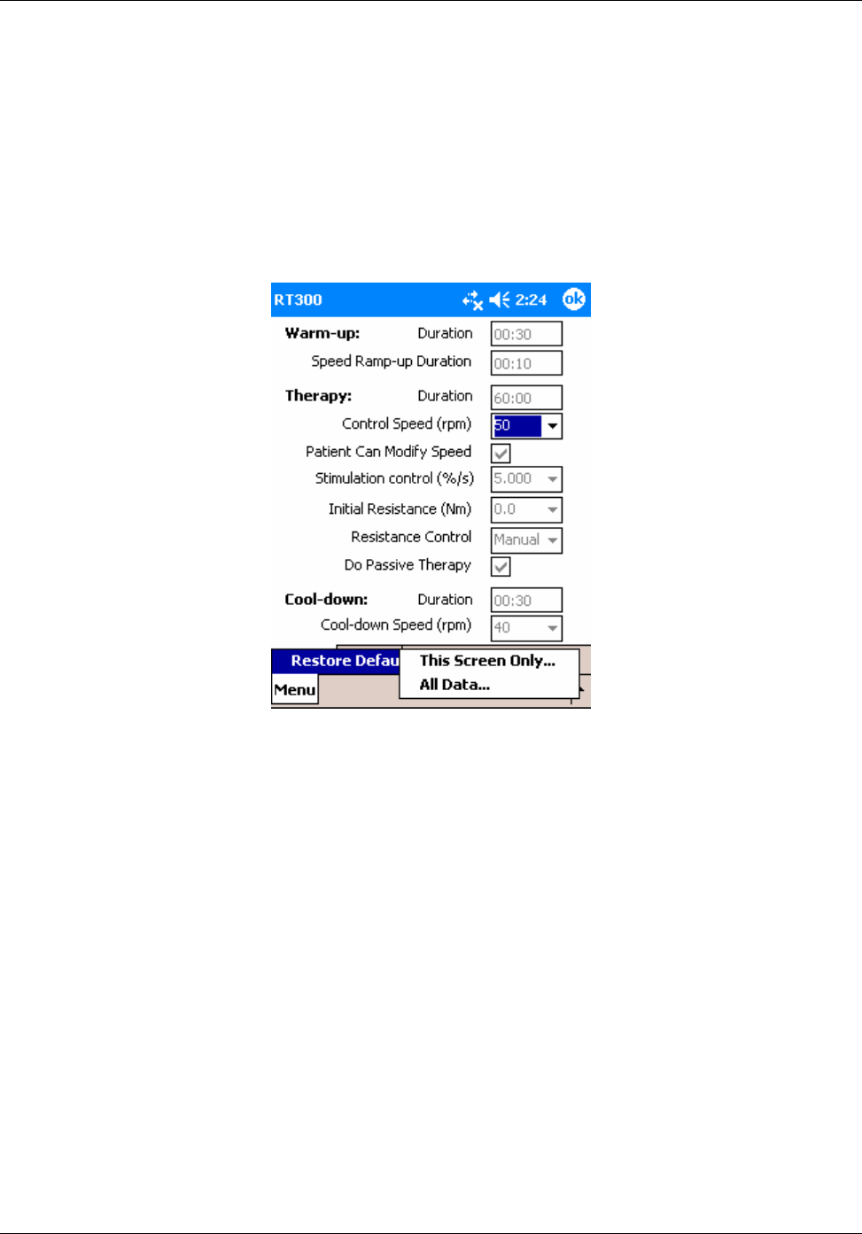
Restoring default values
To restore values to their default settings:
1. Tap on the menu button
2. Tap Restore Defaults
Select either This Screen Only to restore the values displayed on the currently shown screen OR All Data
to restore all values on all of the configuration pages to their default values.
Figure 39 Restoring default values
Troubleshooting
44 • RT300-S User Manual 2005 Restorative Therapies Inc
Troubleshooting
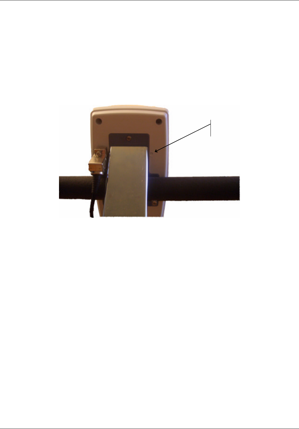
Resetting the Controller
You may need to reset the RT300-S System controller in some situations, for example, if the controller
does not respond when you tap the screen.
To reset the controller:
1. Press the Reset button on the back of the controller using the stylus or a pen.
Figure 40: Reset button on controller
2. Wait until the controller displays the Therapy Session screen.
Reset
button
Care of the RT300-S System
2005 Restorative Therapies Inc RT300-S User Guide • 45
Care of the RT300-S System
Cleaning and Maintenance
Regularly cleaning the equipment prevents a build-up of dirt.
Always unplug the power cord from the power outlet before you start cleaning.
• Never use solvent-based or corrosive on the RT300-S System.
• Wipe the controller screen with a dry clean cloth. Don’t use any water - make sure no moisture gets
into the controller.
• Use a damp, soft cloth to clean the RT300-S System surfaces.
• Take care not to damage or remove labels during cleaning.
• After 2 years (or 2,000 hours) of use, the controller displays a message to let you know that it is time
for a maintenance check. Contact RTI Technical Support to arrange the service.
Storing the RT300-S
When you are not using the RT300-S System:
• store the RT300-S System equipment in temperatures between –20°C (–4°F) and +50°C (+122°F)
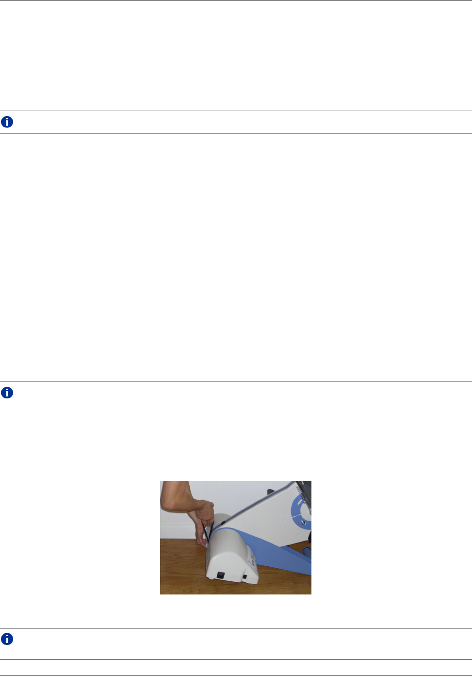
Moving the RT300-S System
Always unplug the power cord from the power outlet and the RT300-S System before moving the device.
The RT300-S System is fitted with castors and a handle to facilitate moving the RT300-S System short
distances over a smooth surface. Hold the handle with one hand and place the other hand under the
power unit.
To move the RT300-S System, tilt it backwards as shown in Figure 41 and push it in front of you.
Figure 41 Moving the RT300-S System
The castors are not suitable for the transport on uneven or rough surfaces.
Two people are required to carry the RT300-S System up or down stairs.
Shipping Instructions
46 • RT300-S User Manual 2005 Restorative Therapies Inc
Shipping Instructions
The RT300-S Cycle Ergometer should be shipped in its original packaging.
The package dimensions are: 27” x 23” x 20”
The package weight is: 90lbs
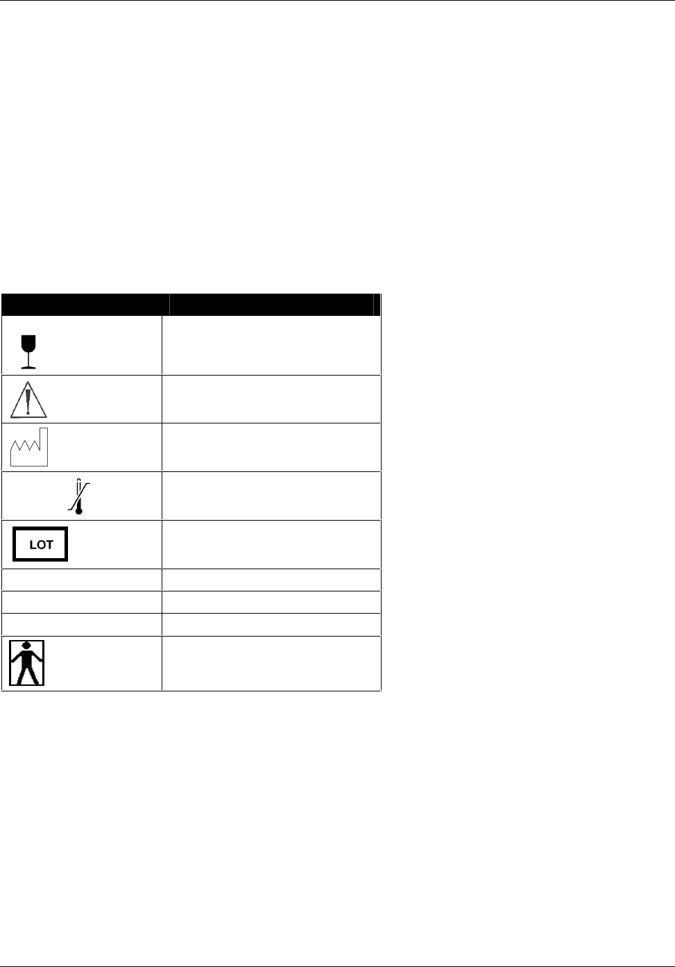
Symbols
Symbol Meaning
Fragile
See instructions for use
Date of manufacture
Temperature limit
Lot number or Batch number
REF 12345 Reference number or Part number
IN 123456 RTI’s Serial Number
Model FA100052 Model Number
Type BF Part
2004-05-30
-20
°
C (-4
°
F)
+50
°
C (+122
°
F)
12345
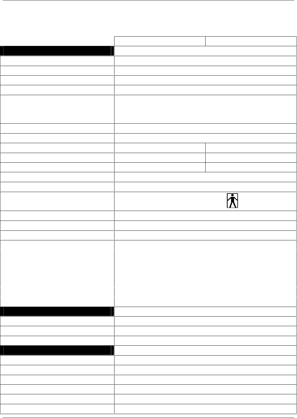
Technical Specifications
2005 Restorative Therapies Inc RT300-S User Guide • 47
Technical Specifications
115V 230V
Motorized Ergometer
Length 31.5” or 80cm
Width 19.3” or 49cm
Height 36.2” – 40.6” or 92 – 103cm
Shipping weight 86lbs or 40kg
Length of pedal:
• RT300-S 4.3” or 110mm
• RT300-S-P (pediatric) 4.3” or 110mm
Speed range 0 – 55 rev/min (± 2 rev/min)
Torque range 0 – 16Nm (± 1N)
Power connection 115V~, 50/60Hz 230V~, 5/60Hz
Power input 130VA 130VA
Fuses 2 x 1.6 A 250V slow 2 x 1.0 A 250V slow
Key materials Aluminum, Steel, Polystyrol, Polyurethane
Protective type I
Degree of protection
Type BF Applied Part
Noise emission Lpa ≤ 70dB (A)
Noise emission value According to DIN 45635-19-01-KL2
Mode of operation This device is for continuous use.
Conditions:
• In use 5°C (41°F) to 40°C (104°F)
0 to 90% Rh
970 to 1030hPa
• Transporting/storing -20°C (-4°F) to +50C (+122°F)
0 to 90% Rh
970 to 1030hPa
Controller
Display / interface Touch-sensitive LCD
Communications Wireless (BlueTooth)
Operating system Windows CE 2003
Inbuilt stimulator
Maximum voltage output 200V
Number of channels 6
Current output per channel 0 – 140mA (± 2mA) with 0 to 1500Ω load
Waveform type Biphasic, charged balanced
Pulse frequency 20Hz
Phase width 0 – 250µs

RT300-S Ergometer Limited Warranty (USA)
This document is important. It contains your Limited Warranty for each of the product(s)
identified below that you purchase (the “Product”) and register with Restorative Therapies Inc.
The terms and conditions of your Warranty, including important limitations on how the Product
should be used, are set out below.
Product Part Number
Warranty Period
RT300-S FA100052 1 year
RT300-S-P FA100053 1 year
Ergometer platform FA100019 1 year
Limited Warranty, Terms and Conditions
A. Introduction
Words which appear in italics, like this, are given defined meanings in clause D below. This
Limited Warranty gives you specific legal rights, and you may also have other rights which vary
from State to State. This Limited Warranty applies in all jurisdictions.
B. Enquiries and Warranty Service
If you have an enquiry about this Limited Warranty or you want to have a Product repaired,
please contact Restorative Therapies Inc. Do not ship Product to us without first obtaining a
Return Material Authorization Number.
2363 Boston St
Baltimore, MD 21224
USA
C. Your Warranties and Rights
3. We, Restorative Therapies Inc ("we"), warrant to you, the owner of the Product ("you"),
that:
a. each Product is reasonably fit for the purpose or purposes for which it is supplied by us;
and
b. each Product will be free from defects in workmanship and materials for the Warranty
Period listed above.
4. If your Product is found not to be reasonably fit for the purpose or purposes for which it
was supplied, or if it has defects in workmanship or materials during the Warranty Period,
we will at our choice either:
a. repair the Product at your home or clinic; or
b. ship the Product to our facility for repair or replacement
5. Unless otherwise required by local laws, where a Product is replaced under clause 2 in this
Section of the Warranty, the warranties set out in the table above will continue to apply for
the unexpired portion of the Warranty Period of the original Product.
Phone:
(800) 609
-
9166
Fax: (410) 534-6263
Email: warranty@restorative-therapies.com
D. Warranty limitations
6. We will not be liable to you or any other person under any circumstances for any incidental
or consequential loss or damage, including without limitation, any liability for third party
claims against you for damages or for Product not being available for use. Our liability will
be no more than the amount you paid for the Product that is the subject of a claim. Some
States do not allow the exclusion or limitation of incidental or consequential damages, so
the above limitation or exclusion may not apply to you.
7. Any implied warranties of merchantability and fitness for a particular purpose are limited to
the Warranty Period. Some States do not allow limitations on how long an implied warranty
lasts, so the above limitation may not apply to you.
8. All terms, warranties and conditions which are not set out in this Warranty as to the state,
quality, fitness or otherwise for purpose, merchantability are expressly excluded and will
not apply to the Product except where such terms, conditions and warranties are implied by
applicable local laws and cannot be excluded or modified.
E. Restrictions on product use
9. The Product is designed and manufactured to operate according to the specifications
contained in the RT300-S Ergometer User Manual.
10. The Product is designed and manufactured to operate within the temperature range of +5°C
(+41°F) to +40°C (+104°F) and the Product should not be subject at any time to
temperatures below -20°C (-4°F) or above +50°C (+122°F) otherwise this Warranty will be
void for the Product.
11. The Product is supplied to you/your clinic/your clinician subject to our Standard Conditions
of Sale. In the event of any inconsistency between the terms of this Warranty and our
Standard Conditions of Sale, our Standard Conditions of Sale will prevail.
12. This Warranty will be void should we find evidence of alteration or repair of the Product or
by anyone other than personnel authorised by us.
13. This Warranty will be void should we find evidence of any misuse, negligence or accident in
respect of the Product by you or any other person.
F. Keywords
Local laws means applicable statutes and other laws of the jurisdiction in which the Product is
supplied to you.
Owner means the person who originally purchased the Product or a person who later acquires
it.
Product means an item of equipment manufactured or supplied by us to you, which has been
identified on the first page of this Warranty.
Warranty Period in relation to a Product, means the period set out opposite the Product on the
first page of this Warranty commencing from the date we ship the Product to the purchaser.
blank

Restorative Therapies Inc
2363 Boston St
Baltimore, MD 21224
USA
Telephone: 1-800-609-9166
Fax: 1-410-534-6263
www.restorative-therapies.com
RT300-S is a trademark of Restorative Therapies Inc
Printed in USA
LB100108 Issue 7 (2110) RV100608 June 2005