Robert Bosch Tool WC18CV Wireless charger system for power tools User Manual WC18C
Robert Bosch Tool Corporation Wireless charger system for power tools WC18C
Contents
- 1. Manual New Part 0
- 2. Manual New Part1
- 3. Manual New 2_0
- 4. Manual New-3
Manual New Part1
-4-
When batteries are not in
tool or charger, keep them
away from metal objects. For example, to
protect terminals from shorting DO NOT place
batteries in a tool box or pocket with nails,
screws, keys, etc. Fire or injury may result.
DO NOT PUT BATTERIES INTO FIRE OR
EXPOSE TO HIGH HEAT. They may explode.
!
WARNING
Do not attempt to disas-
semble the battery or
remove any com ponent projecting from the
battery terminals. Fire or injury may result.
Prior to disposal, protect exposed terminals
with heavy insulating tape to prevent shorting.
Lithium-ion Batteries
If equipped with a lithium-ion battery, the
battery must be collected, recycled or disposed
of in an environ mentally sound manner.
“The EPA certified RBRC Battery
Recycling Seal on the lithium-ion
(Li-ion) battery indicates Robert
Bosch Tool Corporation is
voluntarily participating in an
industry program to collect and recycle these
batteries at the end of their useful life, when
taken out of service in the United States or
Canada. The RBRC program provides a
convenient alterative to placing used Li-ion
batteries into the trash or the munici pal waste
stream, which may be illegal in your area.
Please call 1-800-8-BATTERY for information
on Li-ion battery recycling and disposal
bans/restrictions in your area, or return your
batteries to a Skil/Bosch/Dremel Service
Center for recycling. Robert Bosch Tool
Corporation’s involvement in this program is
part of our commitment to preserving our
environment and conserving our natural
resources.”
!
WARNING
Battery Care
Battery Disposal
FCC Caution:
The manufacturer is not responsible for radio
interference caused by unauthorized
modifications to this equipment. Such
modifications could void the user’s authority to
operate the equipment.
This device complies with Part 15 of the FCC
Rules. Operation is subject to the following
two conditions:
1) This device may not cause harmful
interference, and
2) This device must accept any interference
received, including interference that may
cause undesired operation.
These limits are designed to provide
reasonable protection against harmful
interference in a residential installation. This
equipment generates uses and can radiate
radio frequency energy and, if not installed
and used in accordance with the instructions,
may cause harmful interference to radio
communications. However, there is no
guarantee that interference will not occur in a
particular installation. If this equipment does
cause harmful interference to radio or
television reception, which can be determined
by turning the equipment off and on, the user
is encouraged to try to correct the interference
by one or more of the following measures:
• Reorient or relocate the receiving antenna.
• Increase the separation between the
equipment and receiver.
• Connect the equipment into an outlet on a
circuit different from that to which the
receiver is connected.
• Consult the dealer or an experienced
radio/TV technician for help.
Changes or modifications not expressly
approved by the party responsible for
compliance could void the user’s authority to
operate the equipment.
2610041926 10-15 WC18CV_WC18C 10/7/15 9:07 AM Page 4
-5-
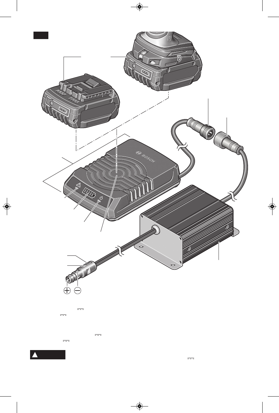
WIRELESS
CHARGING
BATTERY
CHARGING
PLATFORM
12 V PLUG
CABLE SOCKET
POWER SUPPLY
CABLE CONNECTOR
DRAW HOOK
ERROR
INDICATOR (RED)
CHARGER
STANDBY
INDICATOR (GREEN)
CHARGE STATUS
INDICATOR
This charger will only charge the following Wireless charging battery
packs: WCBAT612-WCBAT625. Voltage rating 18V
For most up to date battery compatibility, please refer to www.boschtools.com
!
WARNING
Charger WC18CV
Input voltage: 290V
Output: 18V 3A
Power supply 1600A00AM7 (Designed for
use with 12V automotive DC system)
Input voltage: 13.3 – 16.3V
Output: 290V
Approximate Charging time for 2Ah battery:
45min - 80%, 55min - 100%
Approximate Charging time for 4Ah battery:
75min - 80%, 95min - 100%
FIG. 1
2610041926 10-15 WC18CV_WC18C 10/7/15 9:07 AM Page 5

-6-
WC18H Holster Assembly
The Bosch power supply and wireless
charger must be used in conjunction with
the wireless charging holster WC18H.
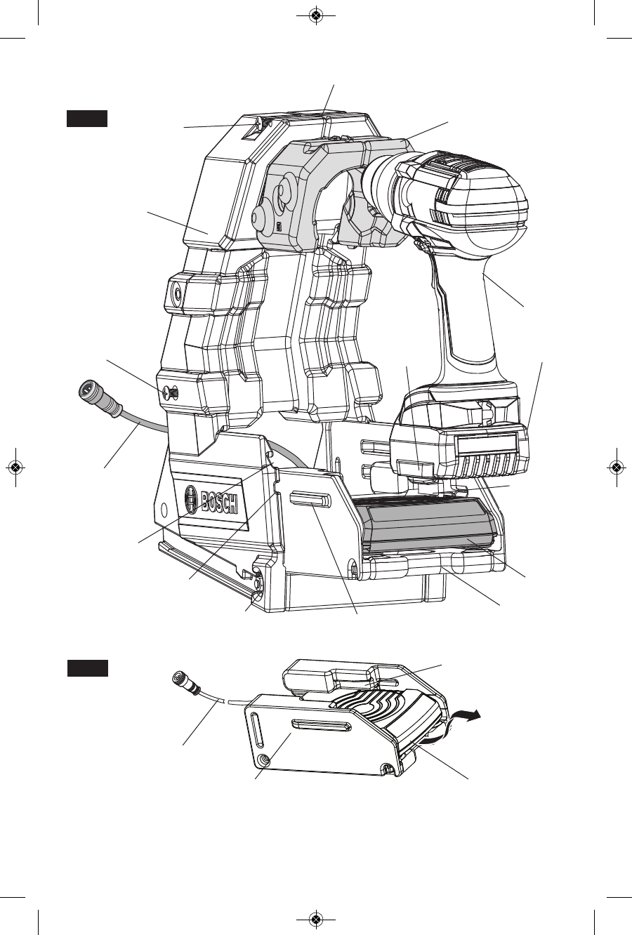
Add/change Holster Inserts
The holster is compatible with the following
Bosch 18V Drill/Drivers and Impact Drivers
through the use of specially-designed inserts
(see Fig. 2a). When purchased as a toolkit, the
correct insert is shipped with the toolkit. When
purchased as a starter kit, the correct insert
should be selected from the Holster Insert
Compatibility table and installed according to the
instructions below.
Note: Refer to Fig. 2a.
1. Remove Screw/Nut 1.
2. Loosen the (2x) Screw 2.
3. Remove installed inserts, pinching the bottom
of inserts and pulling them from the holster.
4. Position new inserts, matching left and right
sides appropriately. Grooves in inserts and
holster should align.
5. Retighten (2x) Screw 2.
6. Reattach and tighten Screw/Nut 1.
Installing the Charger into the Holster
1. Slide the charger into the tray. (Fig. 2b) Be
sure that the charger is fully inserted into the
tray and that the power cord is routed out the
back of the tray.
2. Slide the tray into the holster. For
WCBAT612-WCBAT615 batteries, slide the
tray guide rails into the upper tray guide slot.
For WCBAT620-WCBAT625 batteries, slide
the tray guide rails into the lower tray guide
slot. Be sure to route the power cord through
the back of the holster. (Fig. 2a)
Removing the Charger from the Holster
1. Unplug the power cord from power supply
2. Remove the tray from the holster (Fig. 2a)
3. Remove the charger from the tray by first
pulling charger up, then out of the tray (Fig.
2b).
Holster-Compatible Tool Insert
DDH181
HDH181
DDH181X
HDH181X
1
DDS181
DDS181A
HDS181
HDS181A
DDS182
HDS182
DDS183
HDS183
2
25618 3
IDH182 4
2610041926 10-15 WC18CV_WC18C 10/7/15 9:07 AM Page 6
-7-
POWER
CORD
HOLSTER
TRAY
BOLT 1 TRAY GUIDE
RAIL
BATTERY
GUIDE SLOT
BATTERY
RAIL
LOWER TRAY
GUIDE SLOT
UPPER TRAY
GUIDE SLOT
TRAY
CHARGER
CHARGER
TOOL
BATTERY
SCREW 2
SCREW 1
NUT 1
INSERT
BATTERY
GUIDE SLOT
FIG. 2a
FIG. 2b
POWER
CORD
2610041926 10-15 WC18CV_WC18C 10/7/15 9:07 AM Page 7
-8-
Installation
The Bosch power supply and wireless charger
must be used in conjunction with the wireless
charging holster WC18H. The holster allows
secure installation in the cargo areas of a
vehicle, either fastened to a shelf or to a wall.
Users with Sortimo® van racking systems may
opt to install the holster between standard
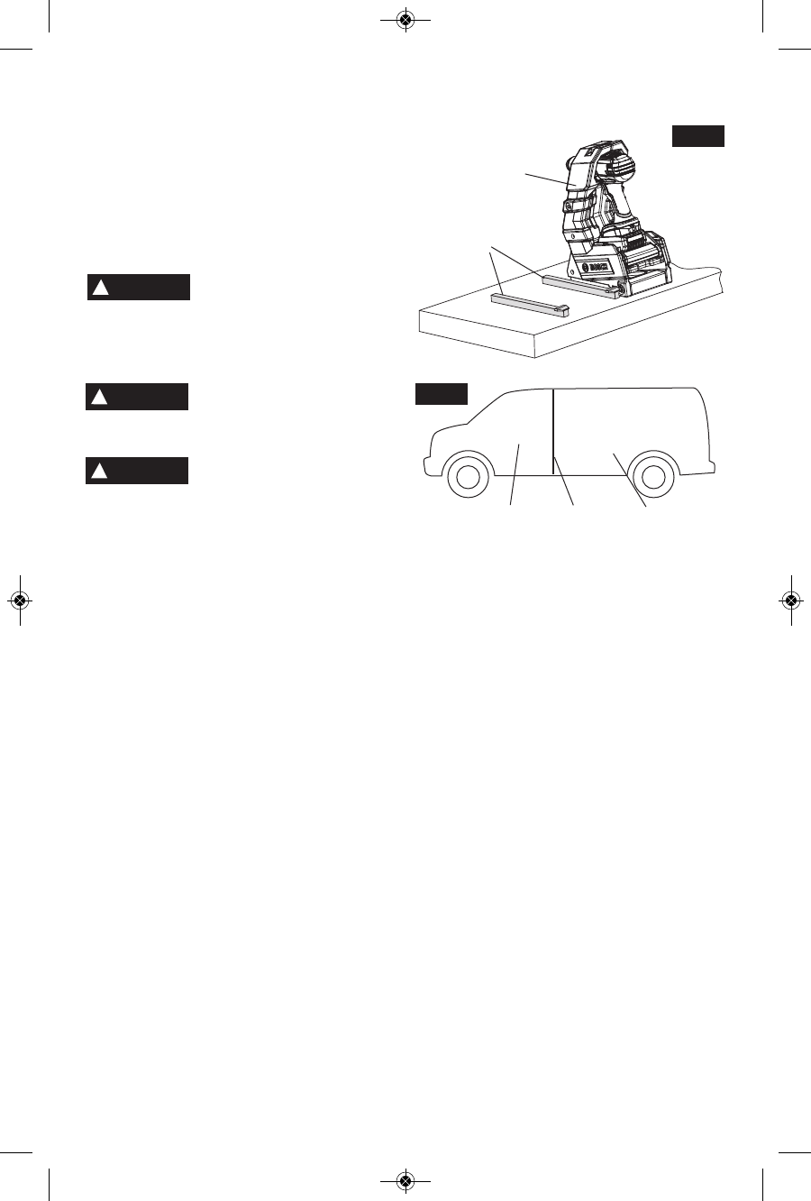
Sortimo® guide rails (Fig. 3).
Unplug power supply and
charger from outlet before
installation, storage, attempting any
maintenance or cleaning. Such preventive
safety measures reduce the risk of electric
shock or fire.
Do not use wireless
charging frame WC18F in
vehicle. Charging frame may break and lead to
personal injury.
Do not install power supply
and wireless charging
holster in vehicles without a permanent
barrier between cargo and passenger areas.
Do not install power supply and wireless
charging holster in vehicle passenger area.
Power supply and wireless charging holster
must be installed in vehicle cargo areas
according to mounting instructions. Failure to
properly install power supply and wireless
charging holster in a vehicle with a permanent
barrier between passenger and cargo areas
could result in personal injury (Fig. 4).
!
WARNING
!
WARNING
!
WARNING
FIG.3
HOLSTER
WITH TOOL
SORTIMO®
GUIDE RAIL
PASSENGER
AREA CARGO
AREA
PERMANENT
BARRIER
FIG.4
2610041926 10-15 WC18CV_WC18C 10/7/15 9:07 AM Page 8
-9-
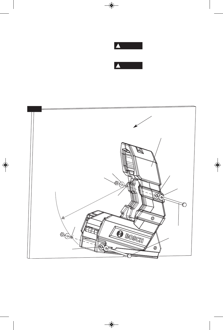
Holster Side Mounting Instructions
The holster may be mounted to shelf or
workbench side walls through the side
mounting holes using the hardware provided
(Fig. 5).
1. Determine desired mounting position and
orientation. Holster may be mounted from
either its left or right side. See Fig. 6a for
acceptable mounting positions.
2. If mounting holes are not available, mark
and pre-drill holes for side mounting bolts.
Side mounting bolt spacing is 10 inches
(254mm).
3. Remove Bolt 1 (Fig. 2a) from bottom side
mounting hole.
4. Attach holster to wall as shown in Fig. 5
Fasten holster securely to
side walls. Holster not
securely fastened may become dislodged
and lead to personal injury
Mount holster in only
r e c o m m e n d e d
orientations. Failure to properly orient
holster may cause holster and/or power tool
to become dislodged and lead to personal
injury.
!
WARNING
!
WARNING
R 10" (254mm)
FIG. 5
HOLSTER
WALL
SIDE
MOUNTING
BOLT* (2x)
TOP
SIDE MOUNTING
HOLE
BOTTOM
SIDE MOUNTING
HOLE
WASHER*
WASHER*
HOLE A
HOLE B
NUT*
* Hardware included with holster
2610041926 10-15 WC18CV_WC18C 10/7/15 9:07 AM Page 9
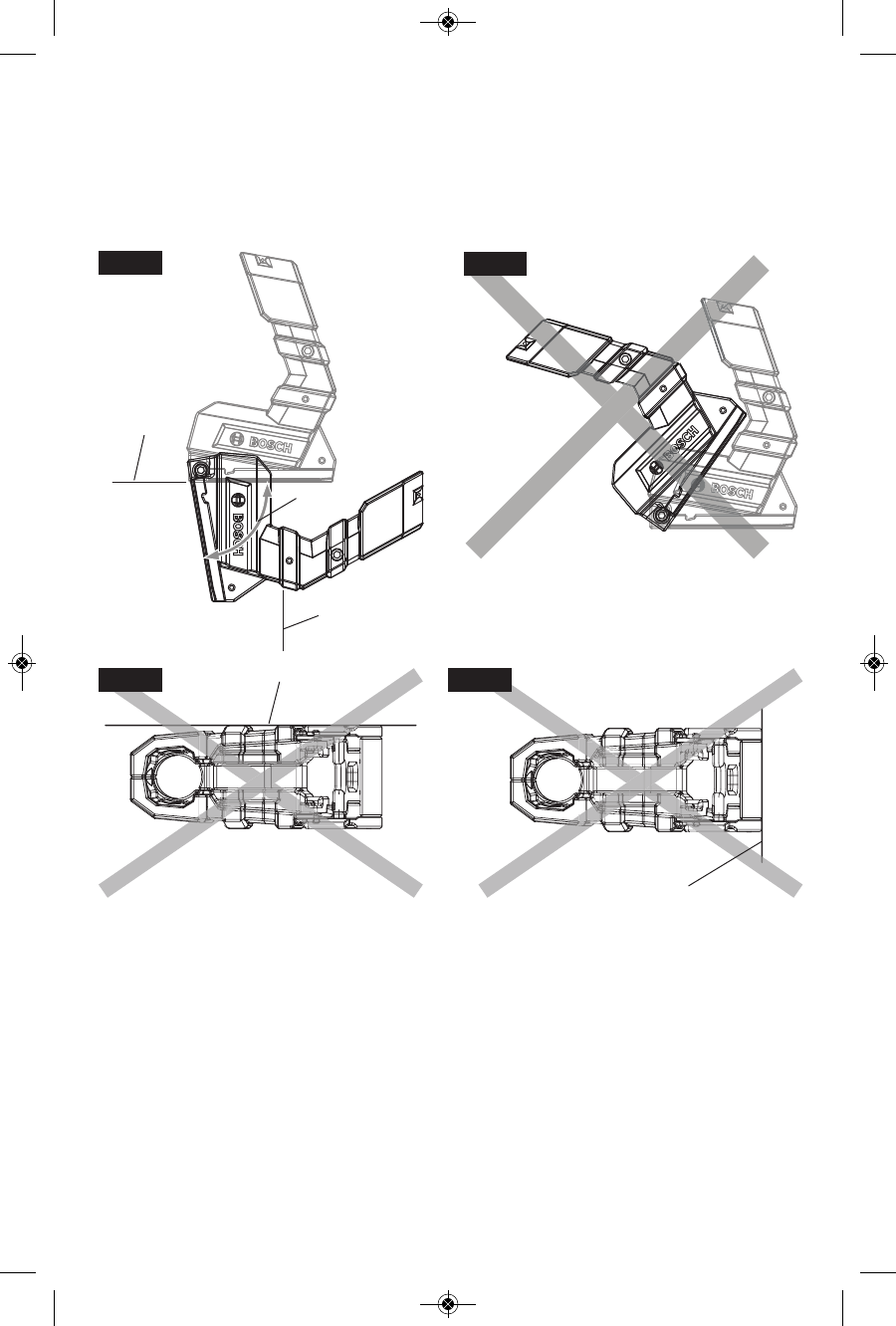
FIG. 7bFIG. 7a
CEILING
WALL
-10-
Holster Side Mounting Orientation
When side mounting the holster, use only the
orientations between 0° and 80° from
horizontal relative to the bottom surface of
the holster (Fig. 6a). Do not mount the
holster in orientations that may cause the
power tool to fall out of holster (Fig. 6b) .
Do not mount the holster to a ceiling (Fig.
7a).
Do not mount the holster to a wall using the
bottom mounting holes (Fig. 7b).
VERTICAL
LINE
0...80°
HORIZONTAL
LINE
FIG. 6a FIG. 6b
2610041926 10-15 WC18CV_WC18C 10/7/15 9:07 AM Page 10
-11-
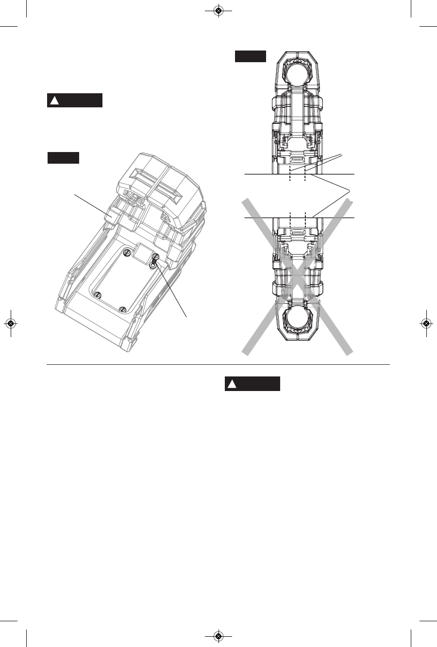
Bottom Mounting Instructions
The holster may be mounted to flat surfaces
through the holes in its base (Fig 8). Do not
mount holster upside down (Fig. 9).
Fasten holster securely to
horizontal surfaces with
appropriate hardware. Holster not securely
fastened may become dislodged and lead to
personal injury.
!
WARNING
FIG. 8
HOLSTER
SCREW (4x)
FIG. 9
SCREW (4x)
HORIZONTAL
SURFACE
Power Supply Installation
1. Determine desired mounting position and
orientation.
2. If mounting holes are not available, mark
and pre-drill holes for the four mounting
screws.
3. Attach power supply using suitable
mounting screws (not included).
4. Securely connect charger cable connector
to the power supply cable socket.
To avoid serious injury, the
power supply must be
mounted securely to vehicle wall or rack
storage system by means of the four
mounting holes on power supply housing.
!
WARNING
2610041926 10-15 WC18CV_WC18C 10/7/15 9:07 AM Page 11
-12-
The battery is supplied partially charged.
Completely charge the battery before using your
cordless tool for the first time. The lithium ion
battery can be charged at any time, without
reducing its service life. Interrupting the charging
procedure does not damage the battery.
Charger Indicators, symbols and meaning
Operating Instructions
If the indicator lights are “OFF”, the charger is
not receiving power from power supply outlet.
Continuous Light Standby Indicator (green)
A continuous green standby indicator
shows that the working voltage is
applied and that the charger is ready
for use.
Flashing Charge Status Indicator
The charge status indicator
flashes while charging. The
number of green bars indicate
the charge level . All five bars
green means that the battery is fully charged.
The light then changes from flashing to
continuous. Note: The tool and battery can be
removed from the charger at any time and
used.
Continuous Error Indicator (red)
A continuous red error indicator
shows that the battery or the charger
temperature is outside of the
permitted temperature range. As
soon as the permitted temperature range is
reached, the charger automatically begins
charging.
Flashing Error Indicator (red)
A flashing red error indicator signals a
different charger fault. See
‘Troubleshooting’ section.
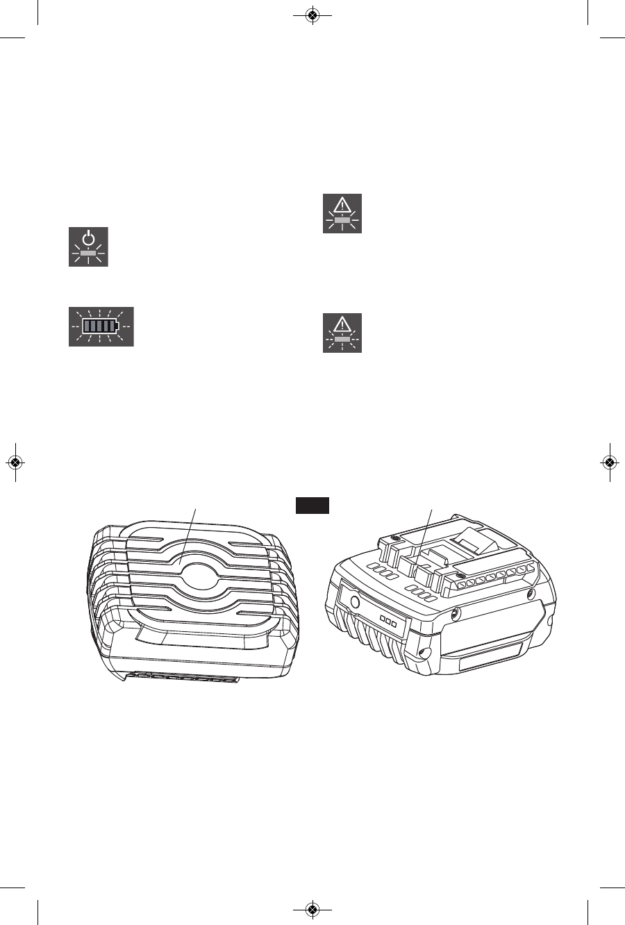
Wireless Charging Battery
FIG. 10
WIRELESS CHARGING
SURFACE STANDARD BATTERY
CONTACTS
2610041926 10-15 WC18CV_WC18C 10/7/15 9:07 AM Page 12