Rockwell Collins 5972410 Perimeter Surveillance Radar User Manual EN 222 3044 657 Installation Guide PSR 500
Rockwell Collins Inc Perimeter Surveillance Radar EN 222 3044 657 Installation Guide PSR 500
Contents
- 1. User Manual 1-40
- 2. User Manual 41-80
- 3. User Manual 81-100
- 4. User Manual 101-125
User Manual 1-40
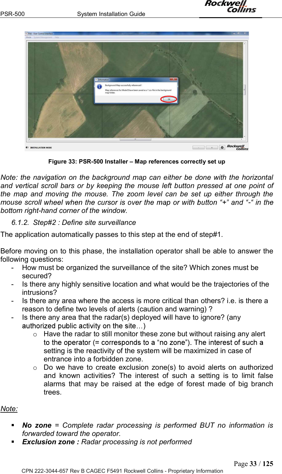
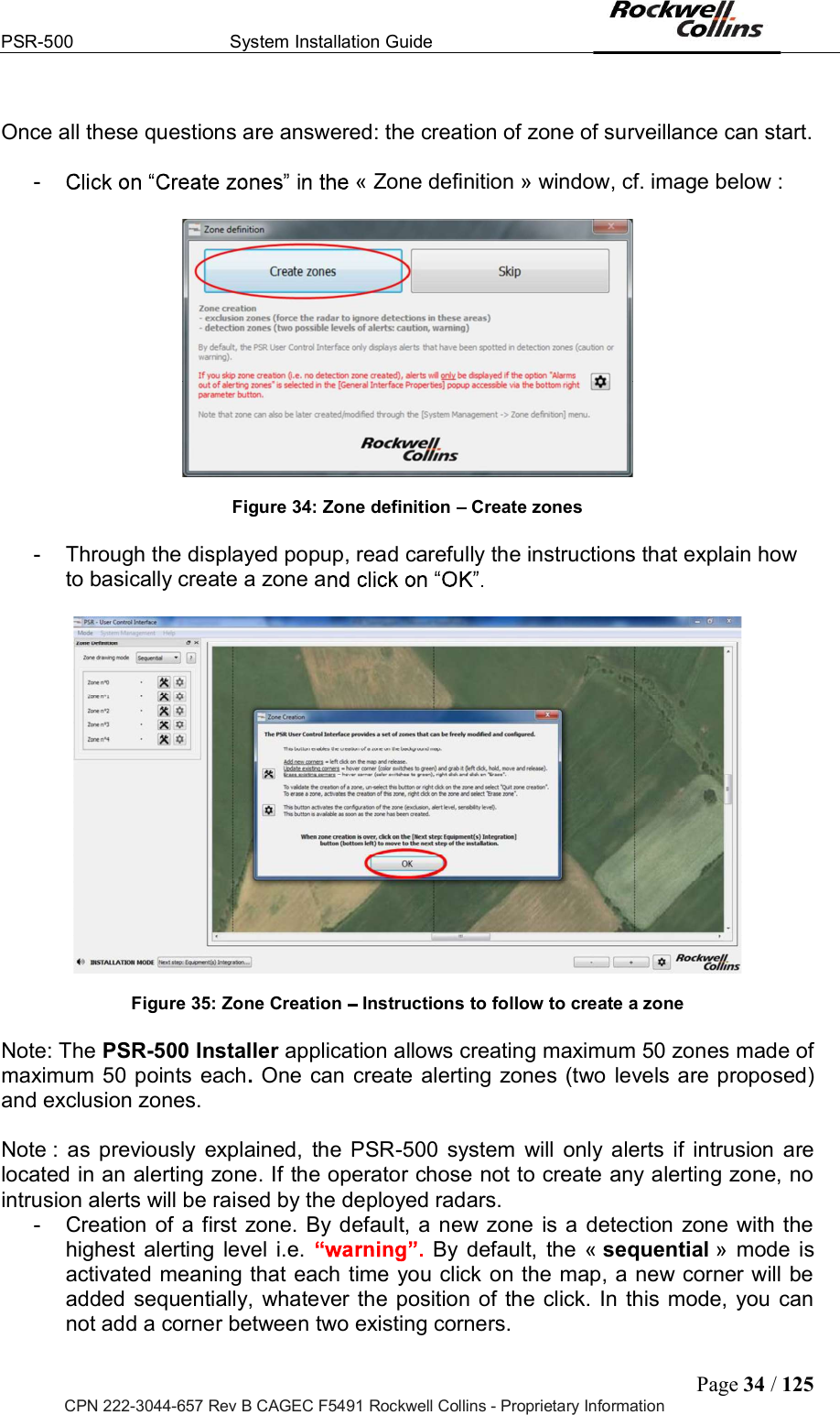
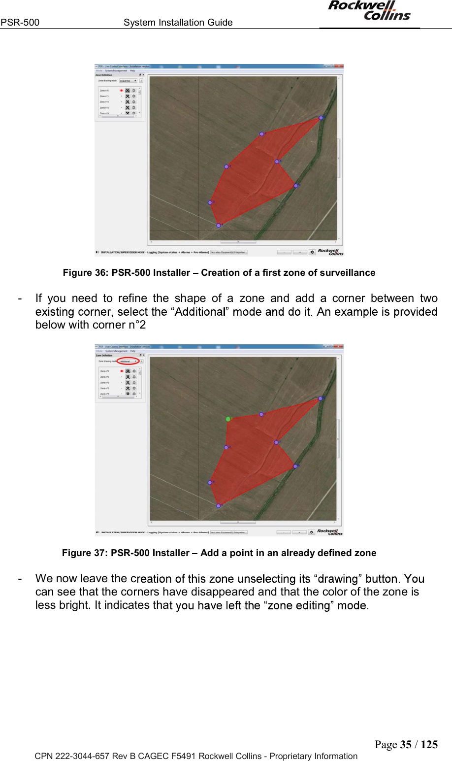
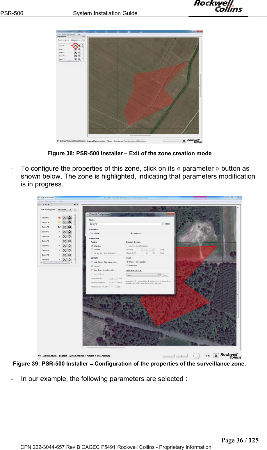
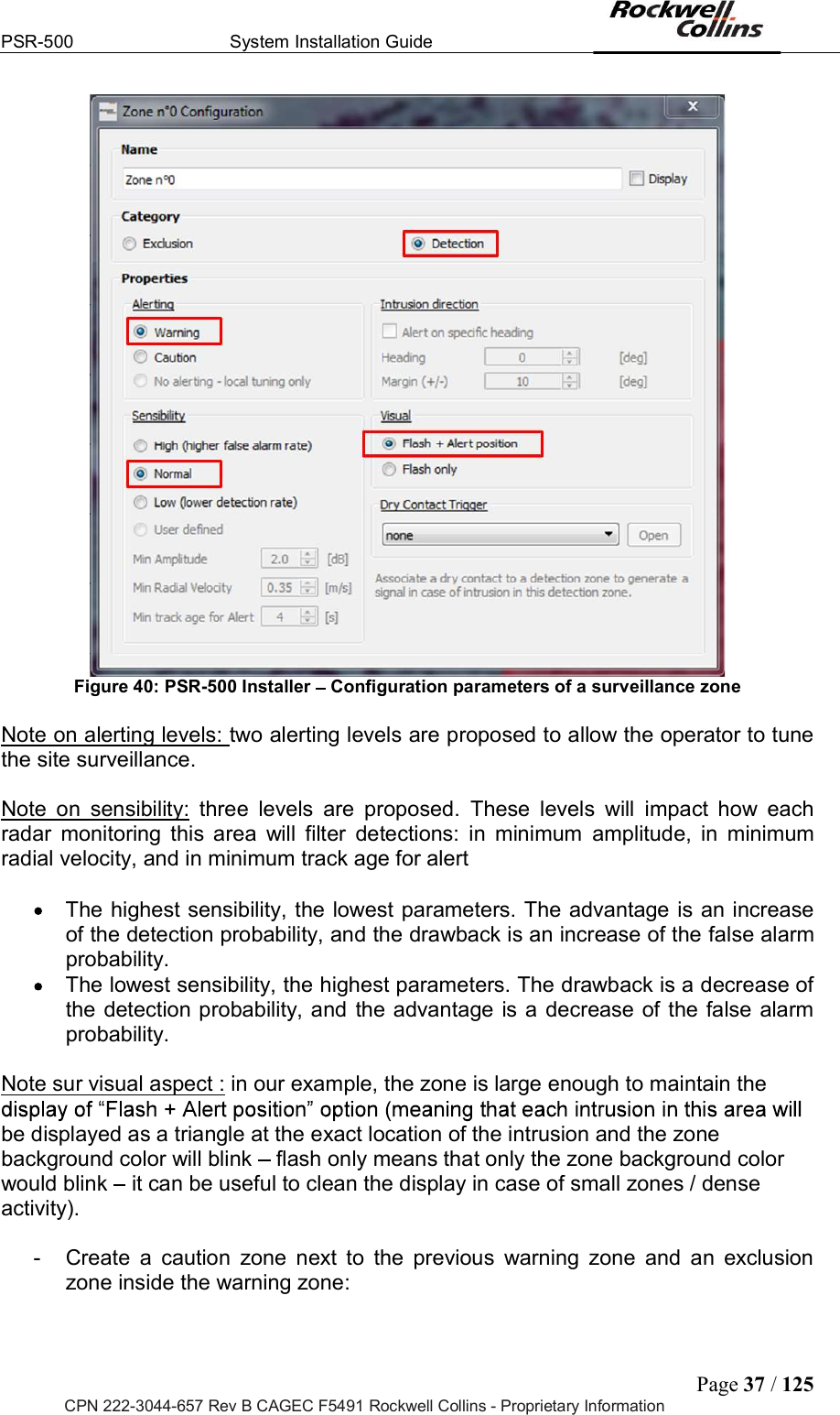
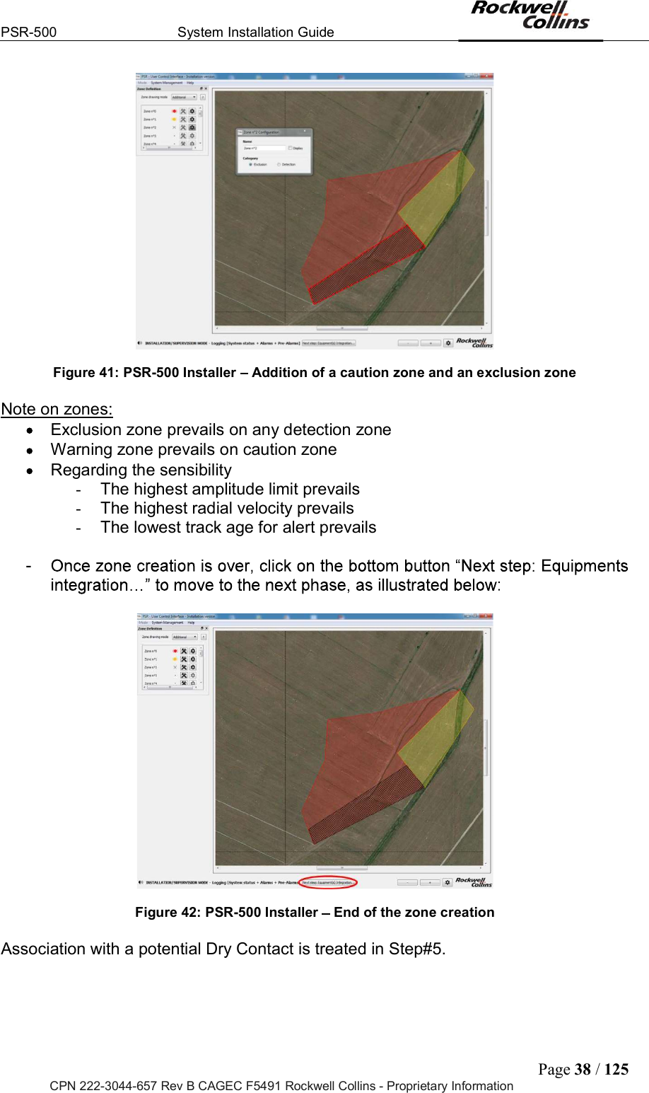
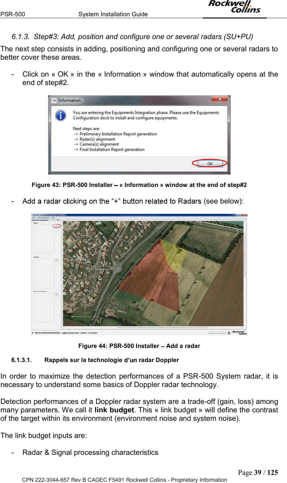
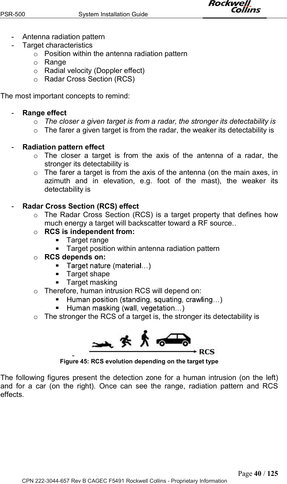
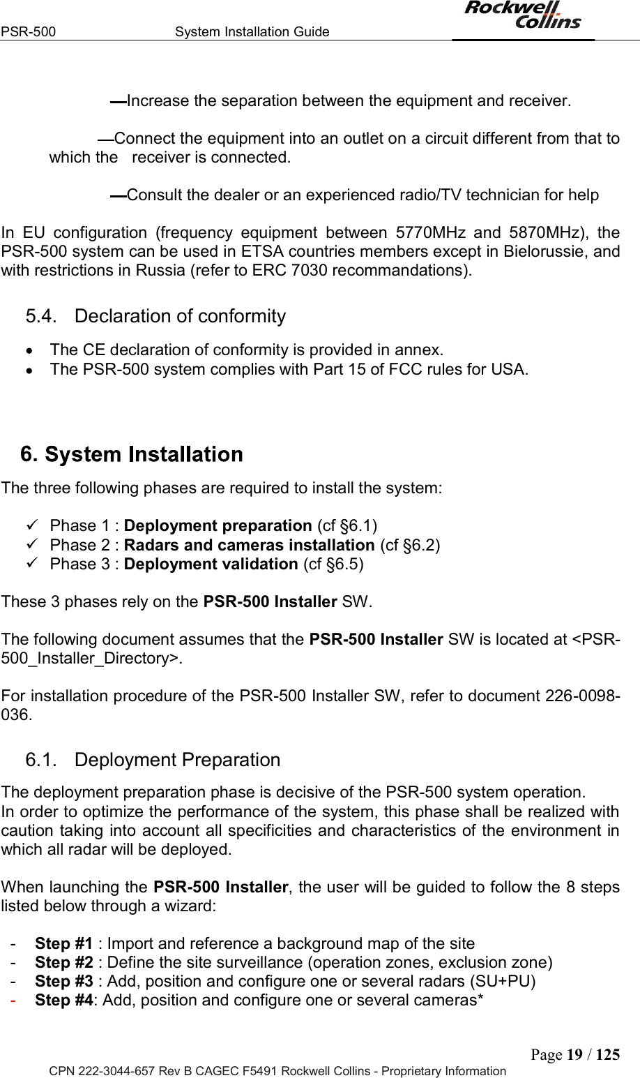
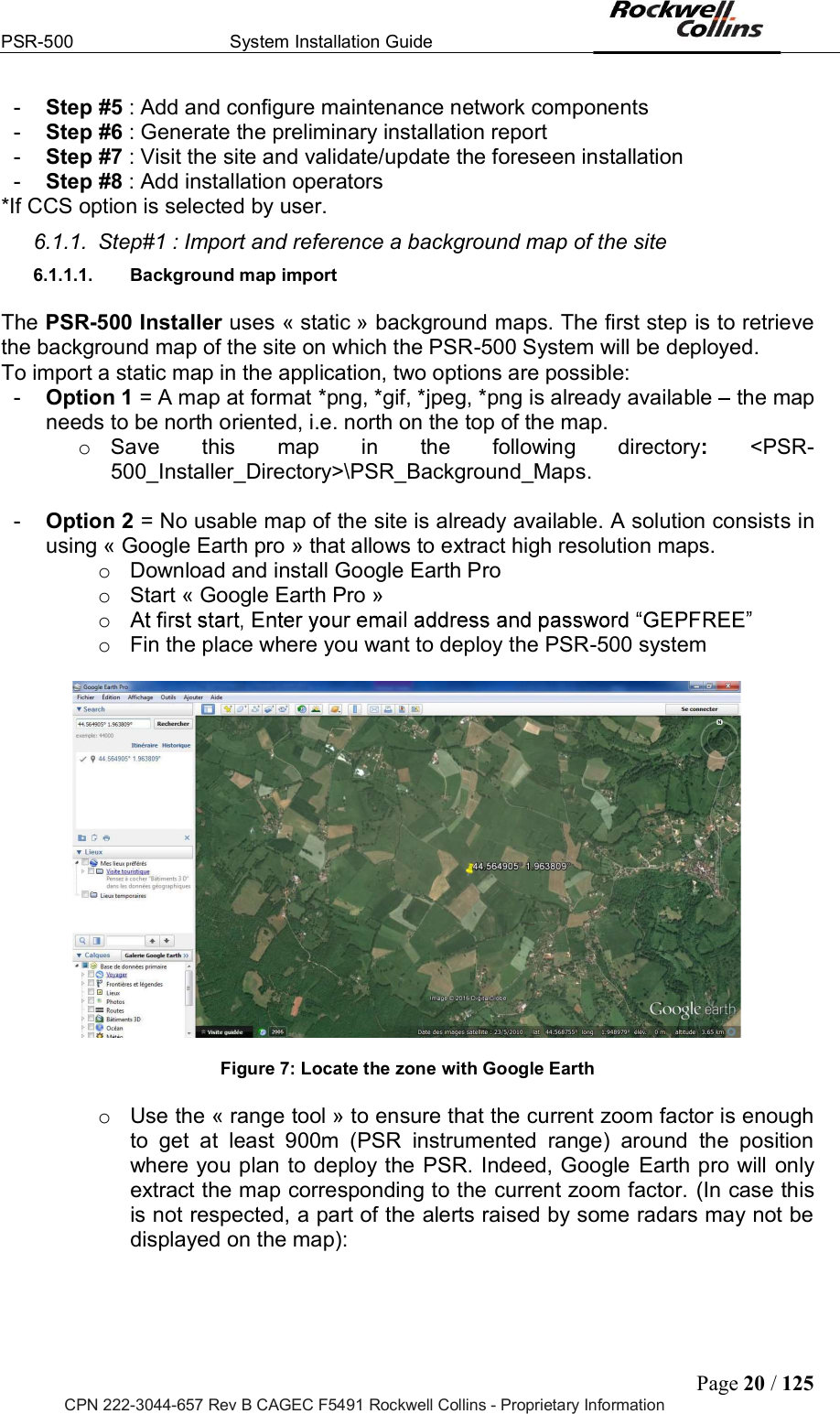
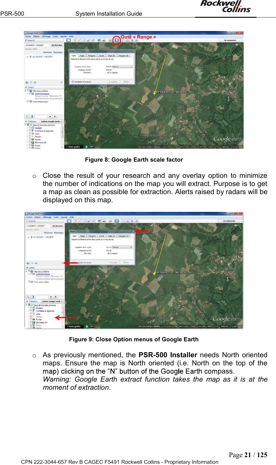
![PSR-500 System Installation Guide Page 6 / 125 CPN 222-3044-657 Rev B CAGEC F5491 Rockwell Collins - Proprietary Information List of Figures Figure 1: Aperçu du système PSR-500 ................................................................................................. 11 Figure 2: PSR-500 system radar detection area for human intrusion detection ................................... 11 Figure 3 Standalone System architecture of PSR-500 system (2 radars configuration) ................... 12 Figure 4: Standalone System architecture of PSR-500 system with CCS option ................................. 13 Figure 5: Integrated System architecture for PSR-500 System (two radars configuration) .................. 14 Figure 6: Integrated System architecture of PSR-500 System with CCS option .................................. 15 Figure 7: Locate the zone with Google Earth ........................................................................................ 20 Figure 8: Google Earth scale factor ....................................................................................................... 21 Figure 9: Close Option menus of Google Earth .................................................................................... 21 Figure 10: Google Earth map Nord oriented ......................................................................................... 22 Figure 11: Save picture on Google Earth .............................................................................................. 22 Figure 12: Unselect display options of Google Earth ............................................................................ 23 Figure 13: Selection of the picture resolution on Google Earth............................................................. 23 Figure 14: Save the map ....................................................................................................................... 24 Figure 15 PSR-500 Installer Authentification window ..................................................................... 24 Figure 16: PSR-500 Installer Creation of a new system configuration .............................................. 25 Figure 17: PSR-500 Installer New System configuration name ......................................................... 25 Figure 18: PSR-500 Installer Select Google Earth map ..................................................................... 25 Figure 19: PSR-500 Installer Confirm that the map is north-oriented ................................................ 26 Figure 20: PSR-500 Installer Select the mode to define map references .......................................... 26 Figure 21: PSR-500 Installer Identification of point [Reference 1] on PSR map................................ 27 Figure 22: PSR-500 Installer Validation du point [Reference 1] sur la carte ...................................... 27 Figure 23: PSR-500 Installer Enter GPS latitude / longitude of point [Reference 1] .......................... 28 Figure 24: PSR-500 Installer Localize point [Reference 1] on Google Earth ..................................... 28 Figure 25: PSR-500 Installer Get GPS coordinate with « pin » tool on Google Earth ....................... 29 Figure 26: PSR-500 Installer Validation of GPS coordinates of point [Reference 1] on the map ...... 29 Figure 27: PSR-500 Installer Identify point [Reference 2] on the PSR map ..................................... 30 Figure 28: PSR-500 Installer Validation of point [Reference 2] on PSR map .................................... 30 Figure 29: PSR-500 Installer Save coordinates of point [Reference 2] ............................................. 31 Figure 30: PSR-500 Installer localize the point [Reference 2] on Google Earth ................................ 31 Figure 31: PSR-500 Installer Get GPS coordinate with « pin » tool on Google Earth ....................... 32 Figure 32: PSR-500 Installer Validation of GPS coordinates of point [Reference 2] on the map ...... 32 Figure 33: PSR-500 Installer Map references correctly set up .......................................................... 33 Figure 34: Zone definition Create zones ............................................................................................ 34 Figure 35: Zone Creation Instructions to follow to create a zone ....................................................... 34 Figure 36: PSR-500 Installer Creation of a first zone of surveillance ................................................ 35 Figure 37: PSR-500 Installer Add a point in an already defined zone ............................................... 35 Figure 38: PSR-500 Installer Exit of the zone creation mode ............................................................ 36 Figure 39: PSR-500 Installer Configuration of the properties of the surveillance zone. .................... 36 Figure 40: PSR-500 Installer Configuration parameters of a surveillance zone ................................ 37 Figure 41: PSR-500 Installer Addition of a caution zone and an exclusion zone .............................. 38 Figure 42: PSR-500 Installer End of the zone creation ...................................................................... 38 Figure 43: PSR-500 Installer « Information » window at the end of step#2 ....................................... 39 Figure 44: PSR-500 Installer Add a radar .......................................................................................... 39 Figure 45: RCS evolution depending on the target type ....................................................................... 40 Figure 46: Detection zone for a human intrusion (left) and for a car (right) .......................................... 41 Figure 47: Illustration radial velocity (3D/2D) ........................................................................................ 41 Figure 48: transverse trajectory case (3D/2D) ...................................................................................... 42 Figure 49: PSR-500 Installer Positioning of a radar on the map ........................................................ 43 Figure 50: Example on an intrusion scenario on a site ......................................................................... 43 Figure 51: Not recommended radar installation .................................................................................... 44 Figure 52: PSR-500 Installer Display the Doppler Rose .................................................................... 44 Figure 53: PSR-500 Installer - Doppler Rose displayed ....................................................................... 45 Figure 54: PSR-500 Installer Setting of the Doppler Rose ................................................................. 45 Figure 55: PSR-500 Installer Doppler Rose aligned with expected intrusions ................................... 46 Figure 56: PSR-500 Installer Possible Installation #1 ........................................................................ 47](https://usermanual.wiki/Rockwell-Collins/5972410.User-Manual-1-40/User-Guide-3726006-Page-6.png)
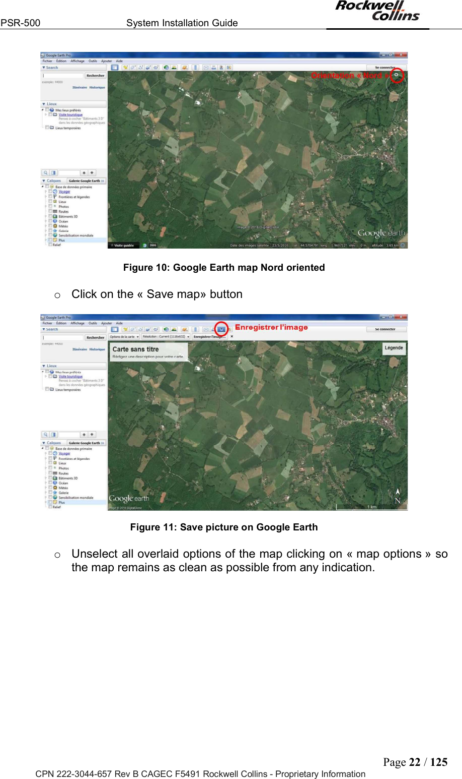
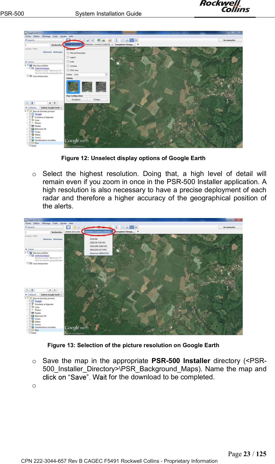
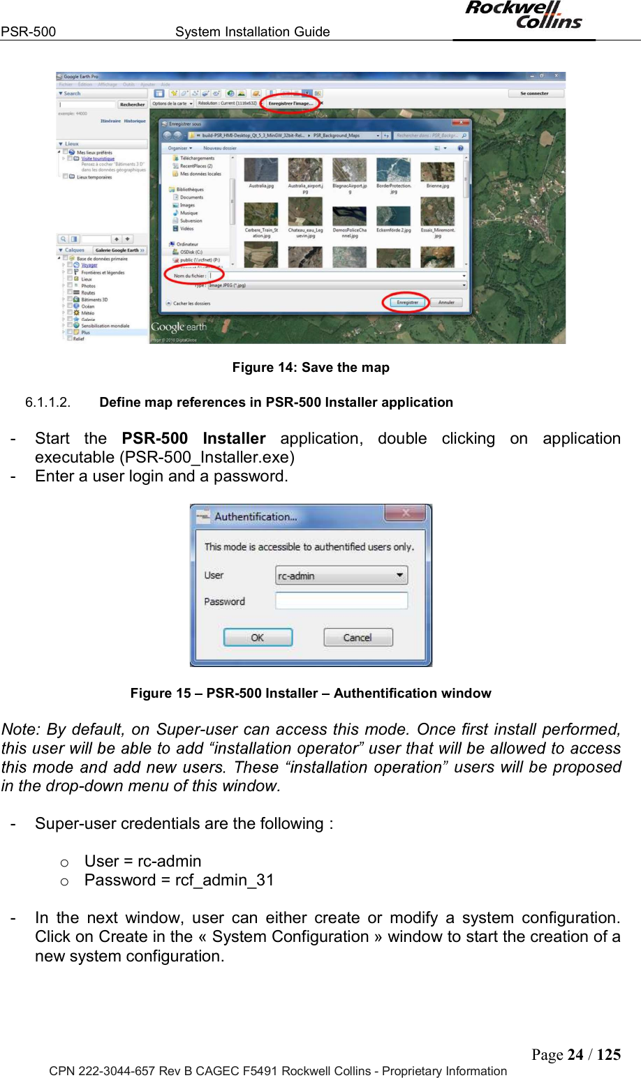
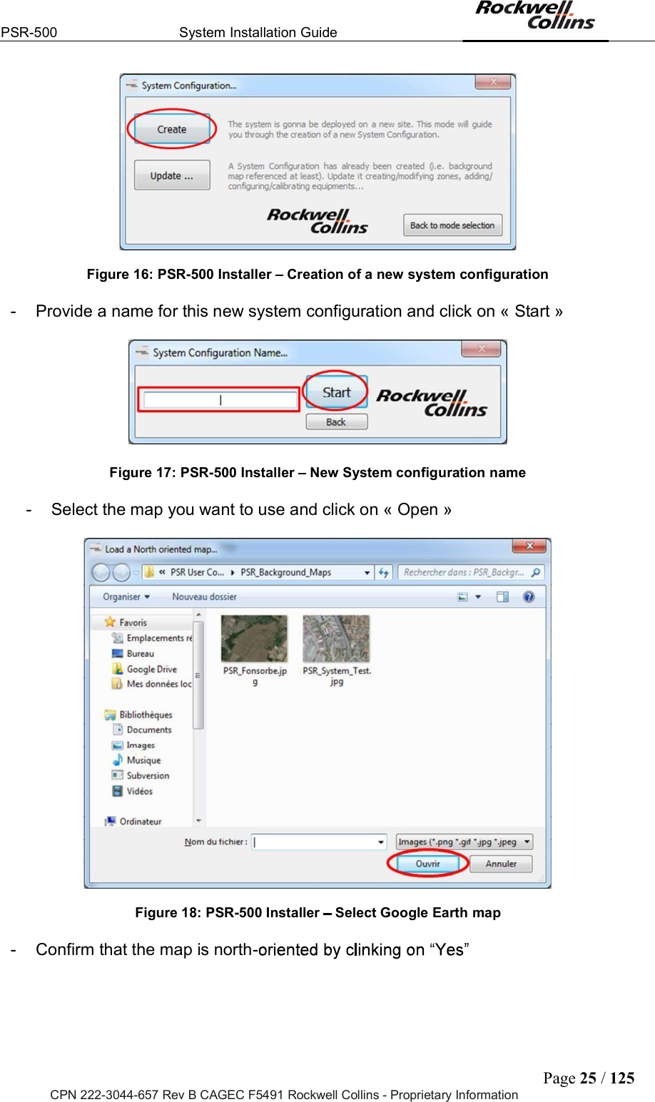
![PSR-500 System Installation Guide Page 26 / 125 CPN 222-3044-657 Rev B CAGEC F5491 Rockwell Collins - Proprietary Information Figure 19: PSR-500 Installer Confirm that the map is north-oriented - Define map references with two known GPS coordinates. Two modes are proposed to define map references the background map : o Mode I = based on GPS coordinates of two references pointed on the map o Mode II = based on the GPS coordinates of the top left and bottom right corner of the map - In our example, we follow mode I. Select Mode I if not already selected and click on « Start » Figure 20: PSR-500 Installer Select the mode to define map references Note that references at the 6th decimal will be required according to PSR Sensors Units high resolution (1.5m). This reference definition phase has to be as much as precise as possible unless locations of alerts will not be positioned accurately on the map. - Identify the point [Reference 1] by clinking on « OK », zoom in to be as precise as possible and define it on the map clicking on it. Use horizontal and vertical scroll bars to navigate on the map. Any click on the map will be taken by the application as the designation of the requested reference.](https://usermanual.wiki/Rockwell-Collins/5972410.User-Manual-1-40/User-Guide-3726006-Page-26.png)
![PSR-500 System Installation Guide Page 27 / 125 CPN 222-3044-657 Rev B CAGEC F5491 Rockwell Collins - Proprietary Information Figure 21: PSR-500 Installer Identification of point [Reference 1] on PSR map - Click « Yes » to confirm point [Reference 1]. If you get the wrong point, click to come back to previous step. Figure 22: PSR-500 Installer Validation du point [Reference 1] sur la carte - You must now enter GPS coordinates of point [Reference 1] (latitude and longitude).](https://usermanual.wiki/Rockwell-Collins/5972410.User-Manual-1-40/User-Guide-3726006-Page-27.png)
![PSR-500 System Installation Guide Page 28 / 125 CPN 222-3044-657 Rev B CAGEC F5491 Rockwell Collins - Proprietary Information Figure 23: PSR-500 Installer Enter GPS latitude / longitude of point [Reference 1] - If you imported your own map, you should already know coordinates of the point. Register then as indicated in Figure 23. If you import your map from Google Earth, locate the point [Reference 1] on Google Earth map, as indicated on the following figure : Figure 24: PSR-500 Installer Localize point [Reference 1] on Google Earth - Zoom in (to be as precise as possible) and recover the GPS coordinates of point [Reference 1]](https://usermanual.wiki/Rockwell-Collins/5972410.User-Manual-1-40/User-Guide-3726006-Page-28.png)
![PSR-500 System Installation Guide Page 29 / 125 CPN 222-3044-657 Rev B CAGEC F5491 Rockwell Collins - Proprietary Information Figure 25: PSR-500 Installer Get GPS coordinate with « pin » tool on Google Earth - Getting back to PSR-500 Installer, enter the GPS coordinates of point [Reference 1] and click on « Validate REF 1 » : Figure 26: PSR-500 Installer Validation of GPS coordinates of point [Reference 1] on the map - Click on « OK » to identify point [Reference 2], zoom in to be as precise as possible and define it on the map clicking on it. Use horizontal and vertical scroll bars to move over the map.](https://usermanual.wiki/Rockwell-Collins/5972410.User-Manual-1-40/User-Guide-3726006-Page-29.png)
![PSR-500 System Installation Guide Page 30 / 125 CPN 222-3044-657 Rev B CAGEC F5491 Rockwell Collins - Proprietary Information Figure 27: PSR-500 Installer Identify point [Reference 2] on the PSR map - Click « Yes » to validate point [Reference 2]. If you get the wrong point, click come back to previous step. Figure 28: PSR-500 Installer Validation of point [Reference 2] on PSR map - You must now enter GPS coordinates of point [Reference 2] (latitude and longitude).](https://usermanual.wiki/Rockwell-Collins/5972410.User-Manual-1-40/User-Guide-3726006-Page-30.png)
![PSR-500 System Installation Guide Page 31 / 125 CPN 222-3044-657 Rev B CAGEC F5491 Rockwell Collins - Proprietary Information Figure 29: PSR-500 Installer Save coordinates of point [Reference 2] - If you imported your own map, you should already know coordinates of the point. Register then as indicated in Figure 29. If you import your map from Google Earth, locate the point [Reference 2] on Google Earth map, as indicated on the following figure : Figure 30: PSR-500 Installer localize the point [Reference 2] on Google Earth - Zoom in (to be as precise as possible) and recover the GPS coordinates of](https://usermanual.wiki/Rockwell-Collins/5972410.User-Manual-1-40/User-Guide-3726006-Page-31.png)
![PSR-500 System Installation Guide Page 32 / 125 CPN 222-3044-657 Rev B CAGEC F5491 Rockwell Collins - Proprietary Information Figure 31: PSR-500 Installer Get GPS coordinate with « pin » tool on Google Earth - Getting back to PSR-500 Installer, enter the GPS coordinates of point [Reference 2] and click on « Validate REF 2» : Figure 32: PSR-500 Installer Validation of GPS coordinates of point [Reference 2] on the map -](https://usermanual.wiki/Rockwell-Collins/5972410.User-Manual-1-40/User-Guide-3726006-Page-32.png)