Rockwell Collins 5972410 Perimeter Surveillance Radar User Manual EN 222 3044 657 Installation Guide PSR 500
Rockwell Collins Inc Perimeter Surveillance Radar EN 222 3044 657 Installation Guide PSR 500
Contents
- 1. User Manual 1-40
- 2. User Manual 41-80
- 3. User Manual 81-100
- 4. User Manual 101-125
User Manual 41-80
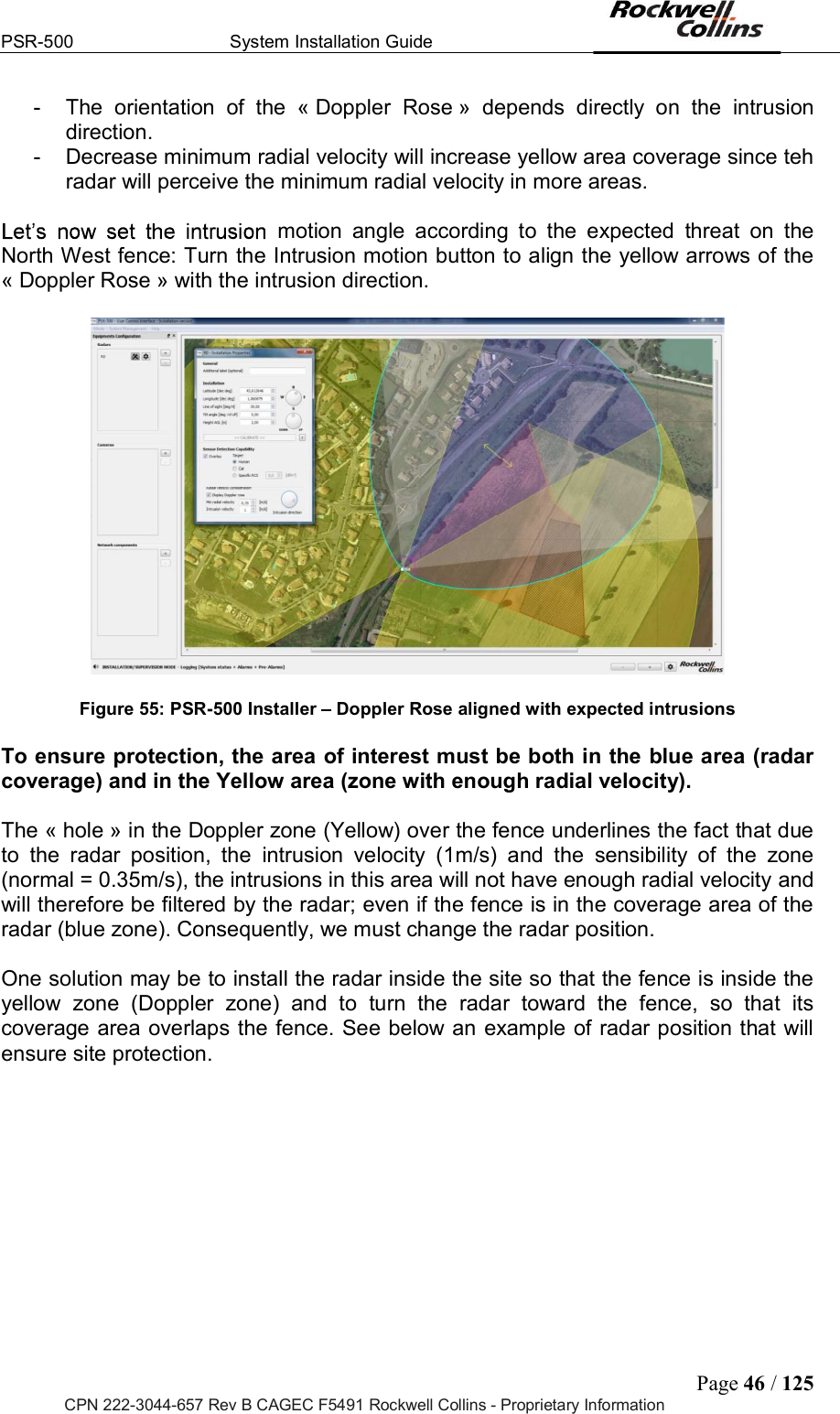
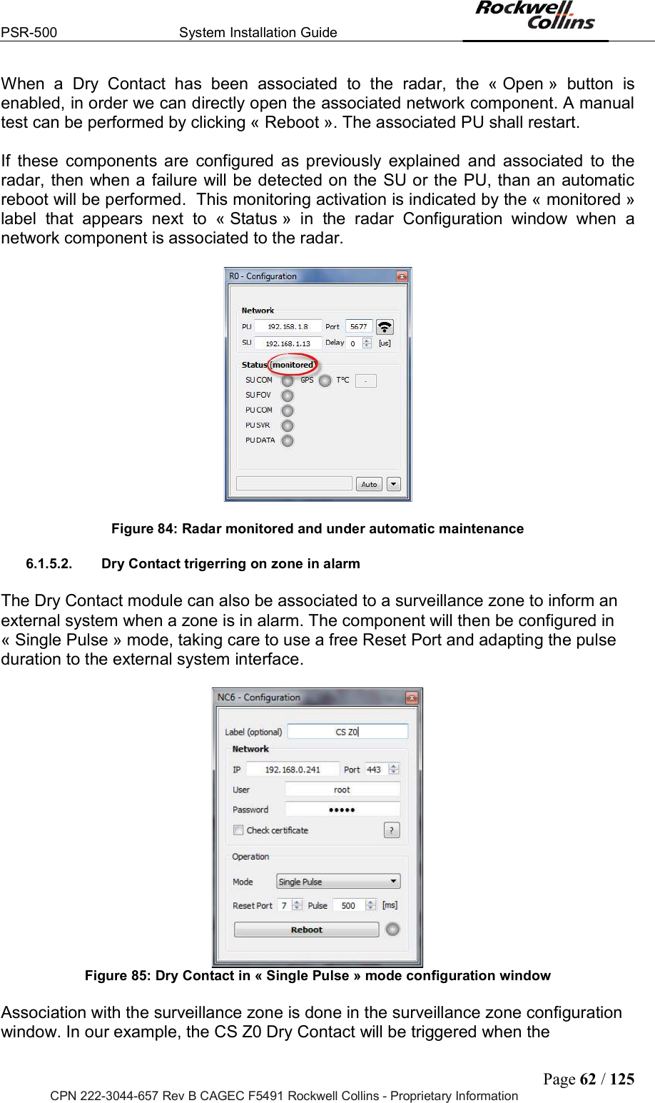
![PSR-500 System Installation Guide Page 45 / 125 CPN 222-3044-657 Rev B CAGEC F5491 Rockwell Collins - Proprietary Information Figure 53: PSR-500 Installer - Doppler Rose displayed The Doppler rose is the yellow area that tells you where the radar will measure more than [min radial velocity] according to the [intrusion velocity] and the [intrusion motion] (yellow arrows). These Figure 54: PSR-500 Installer Setting of the Doppler Rose The « Doppler Rose » takes into account the following properties: - Absolute velocity of the intrusion - Intrusion direction - Minimal radio velocity of the radar By default, the values of these properties are the following one: - Absolute velocity of the intrusion = 1m/s (normal walking velocity) - Intrusion direction = North/South & South/North trajectories. The direction is shown by the yellow arrows. - Min radial velocity = 0.35 m/s (PSR normal sensibility) Note on the « Rose Doppler » configuration: - Increase absolute velocity of the intrusion will increase yellow area coverage since the radar will perceive a minimum radial velocity of 0.35m/s in more areas](https://usermanual.wiki/Rockwell-Collins/5972410.User-Manual-41-80/User-Guide-3726013-Page-5.png)
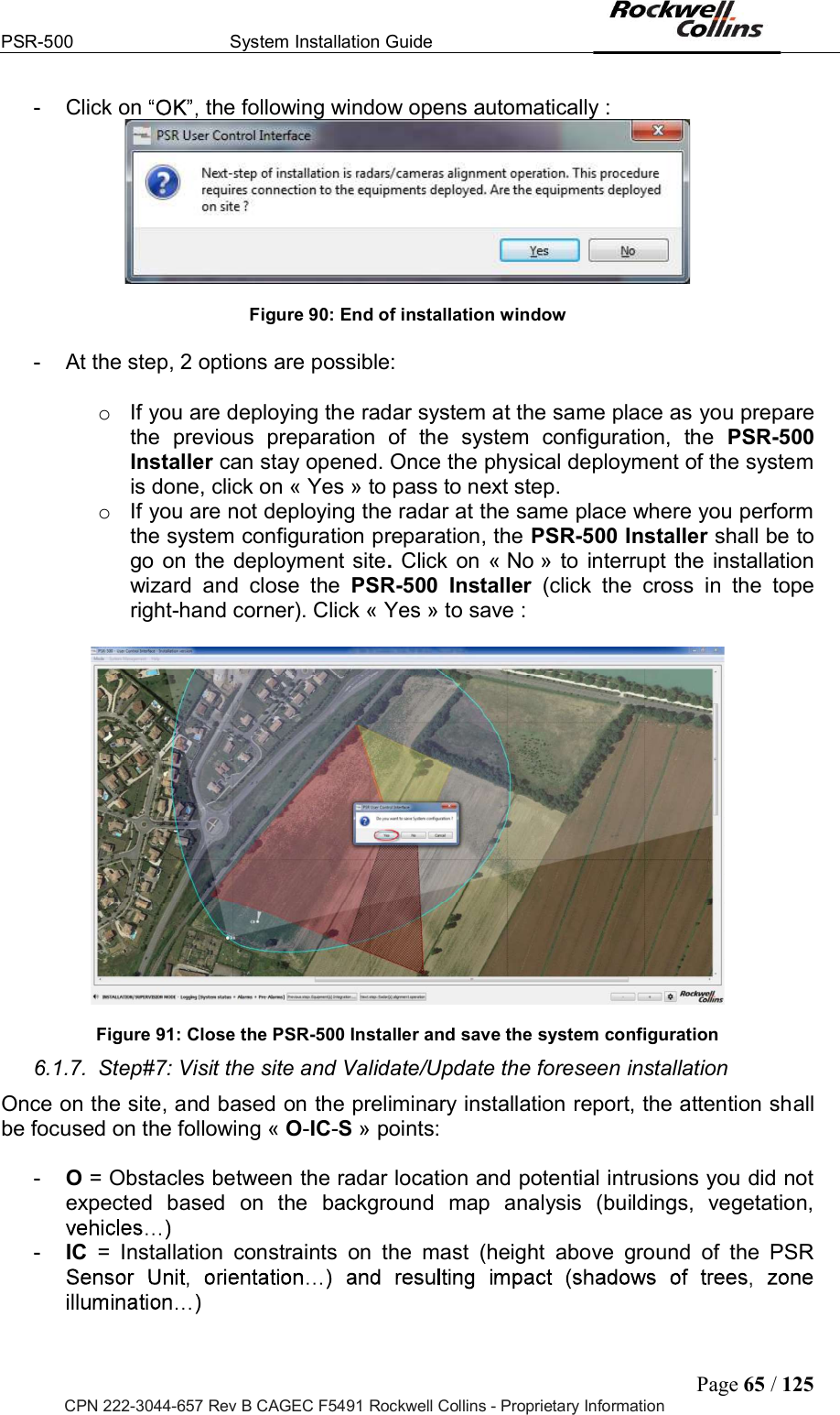
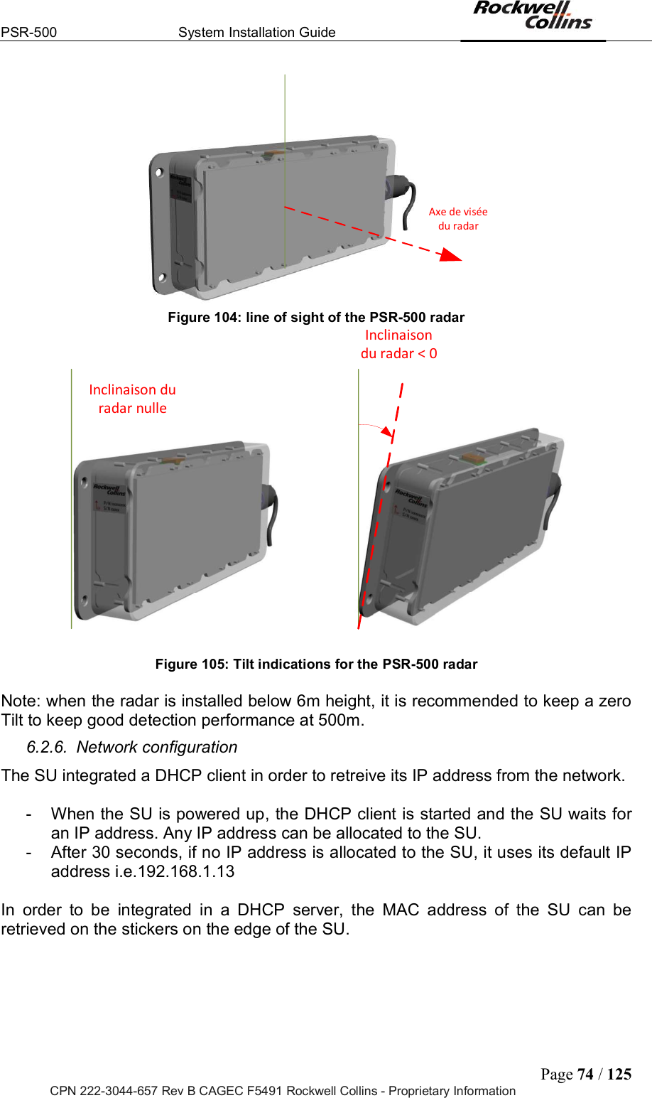
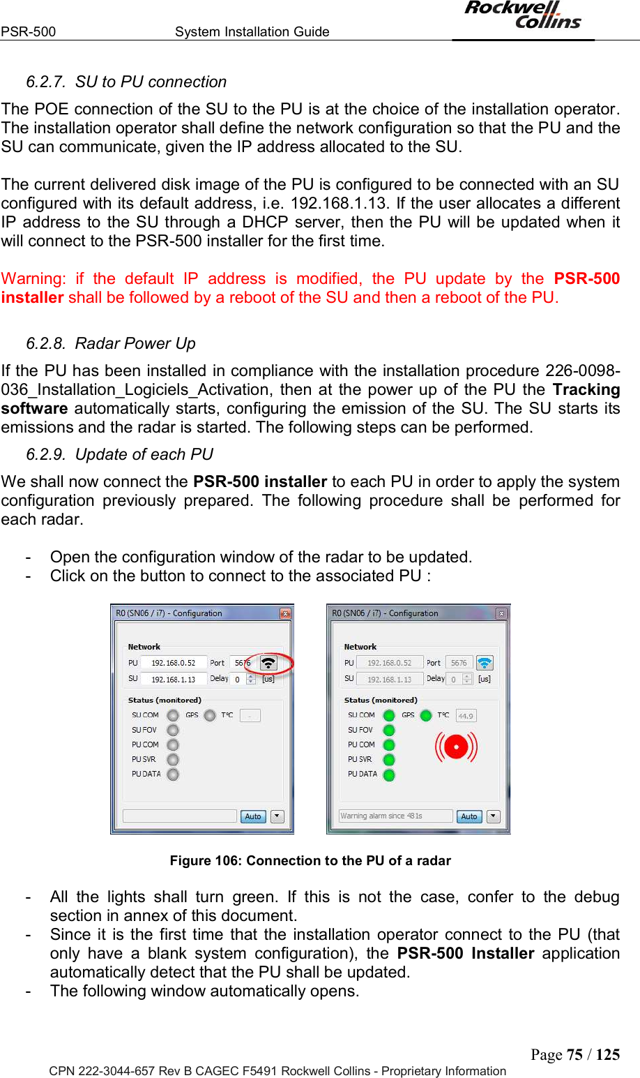
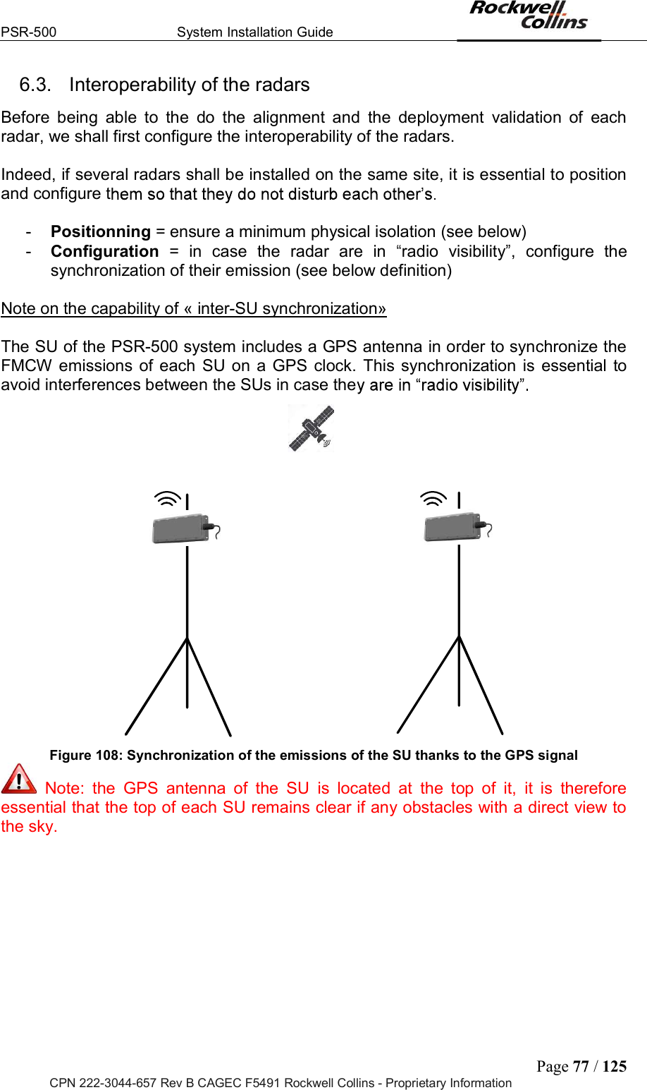
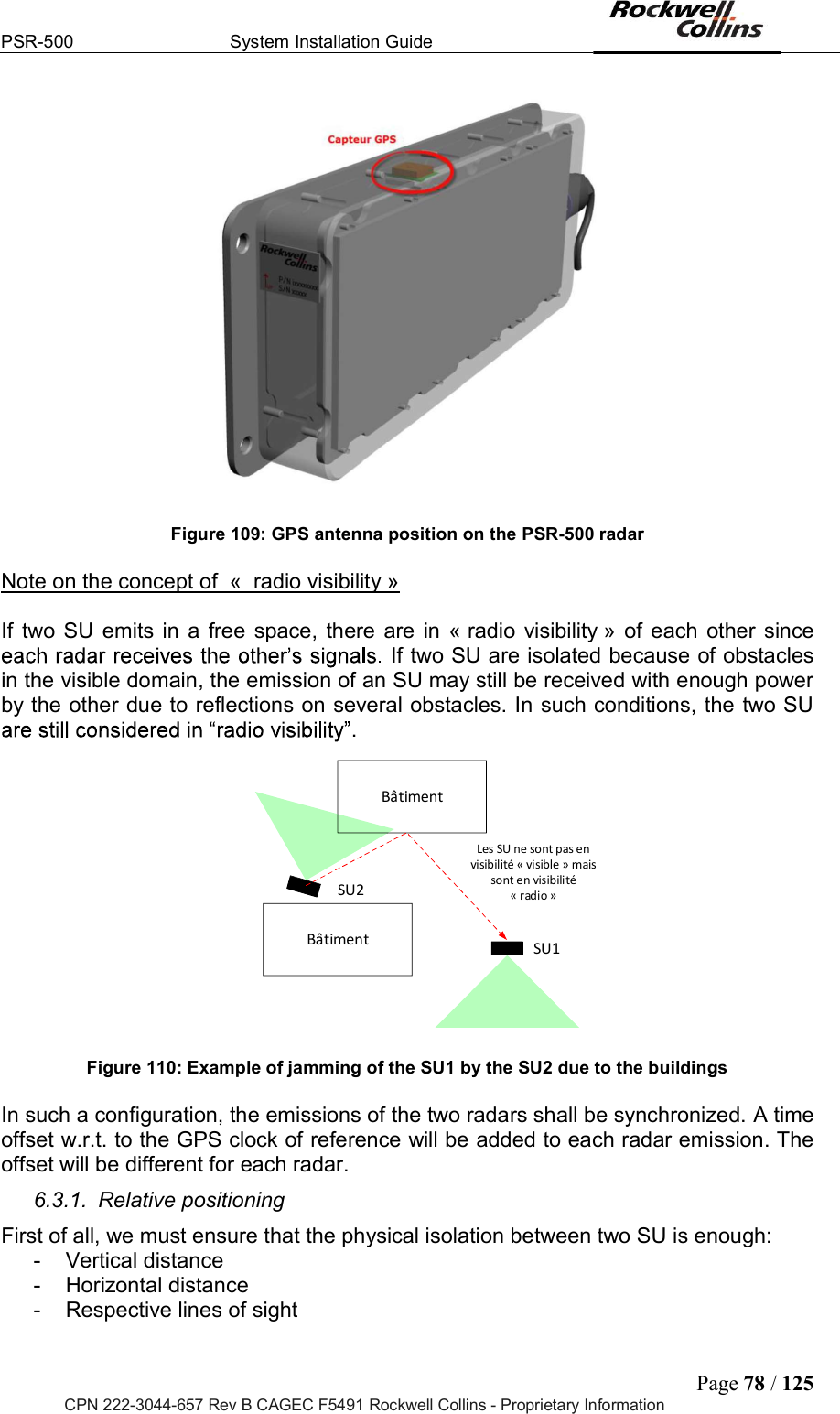
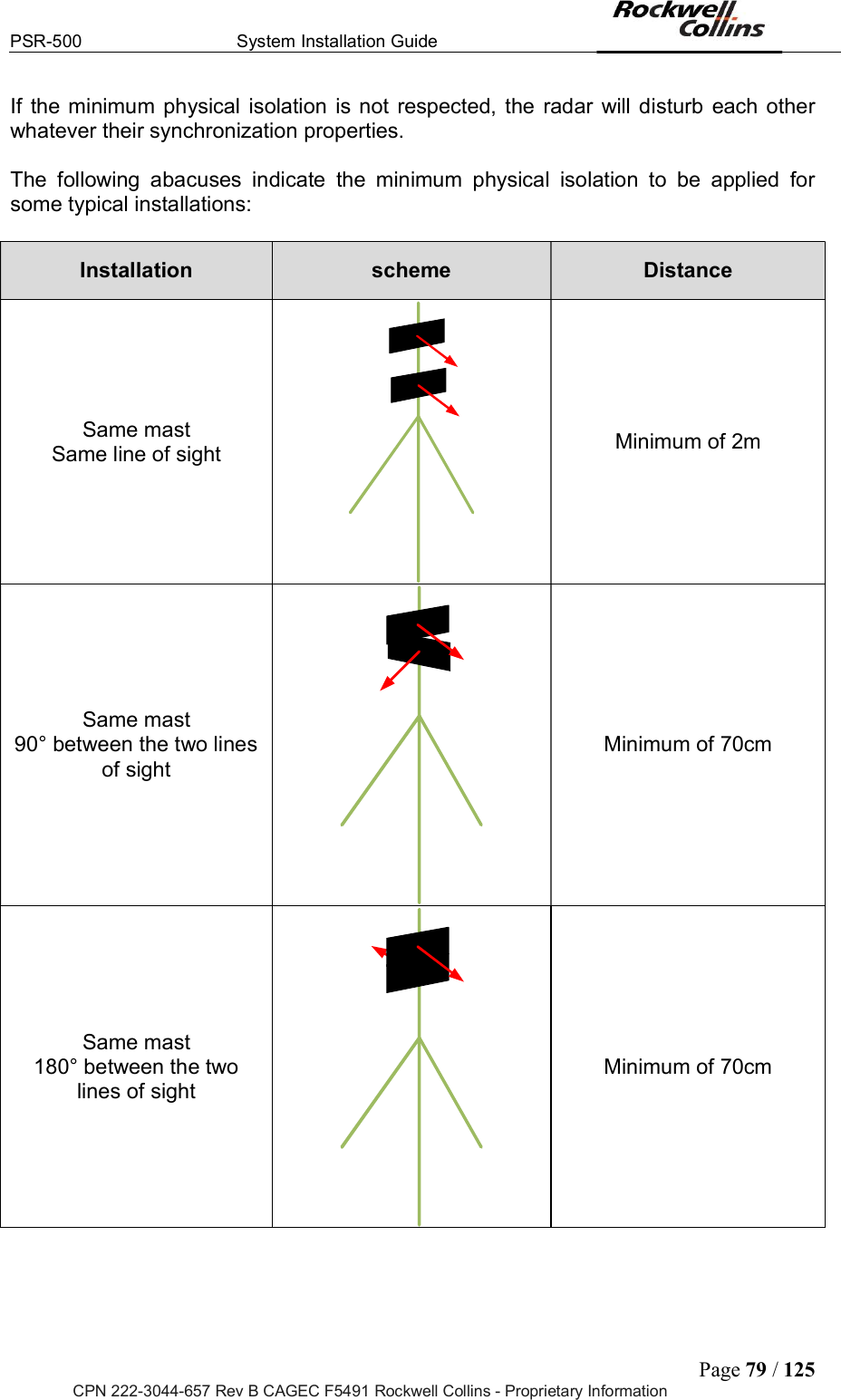
![PSR-500 System Installation Guide Page 80 / 125 CPN 222-3044-657 Rev B CAGEC F5491 Rockwell Collins - Proprietary Information Different mast 180° between the two lines of sight Minimum of 20 m Figure 111: Abacuses of minimum physical isolation Once that physical isolation is respected, we can now proceed with the configuration of radar interoperability. As indicated above, this synchronization is required if several SU are in « radio visibility ». 6.3.2. Radio environment analysis We must first check that there is no jammer in the PSR-500 system radar frequency band of operation [5.77GHZ 5.87GHz]. To do so, we are going to use one of the deployed radar as « spectrum analyser ». First, we are going to set the synchronization of this radar to be sure that it does not « see » any other radar of the deployed PSR-500 system and that the cleanliness of its signal is representative of the radio environment. To set the synchronization of the PSR-500 system radar, we shall tune the offset of the start time of the FMCW waveform w.r.t. the GPS clock. This time offset is called « delay » and is set in microseconds. This « delay » can modified through the radar network property configuration window. Figure 112: setting of a radar delay By default, all radars are synchronized on 0us.](https://usermanual.wiki/Rockwell-Collins/5972410.User-Manual-41-80/User-Guide-3726013-Page-40.png)