Rockwell Collins 5972410 Perimeter Surveillance Radar User Manual EN 222 3044 657 Installation Guide PSR 500
Rockwell Collins Inc Perimeter Surveillance Radar EN 222 3044 657 Installation Guide PSR 500
Contents
- 1. User Manual 1-40
- 2. User Manual 41-80
- 3. User Manual 81-100
- 4. User Manual 101-125
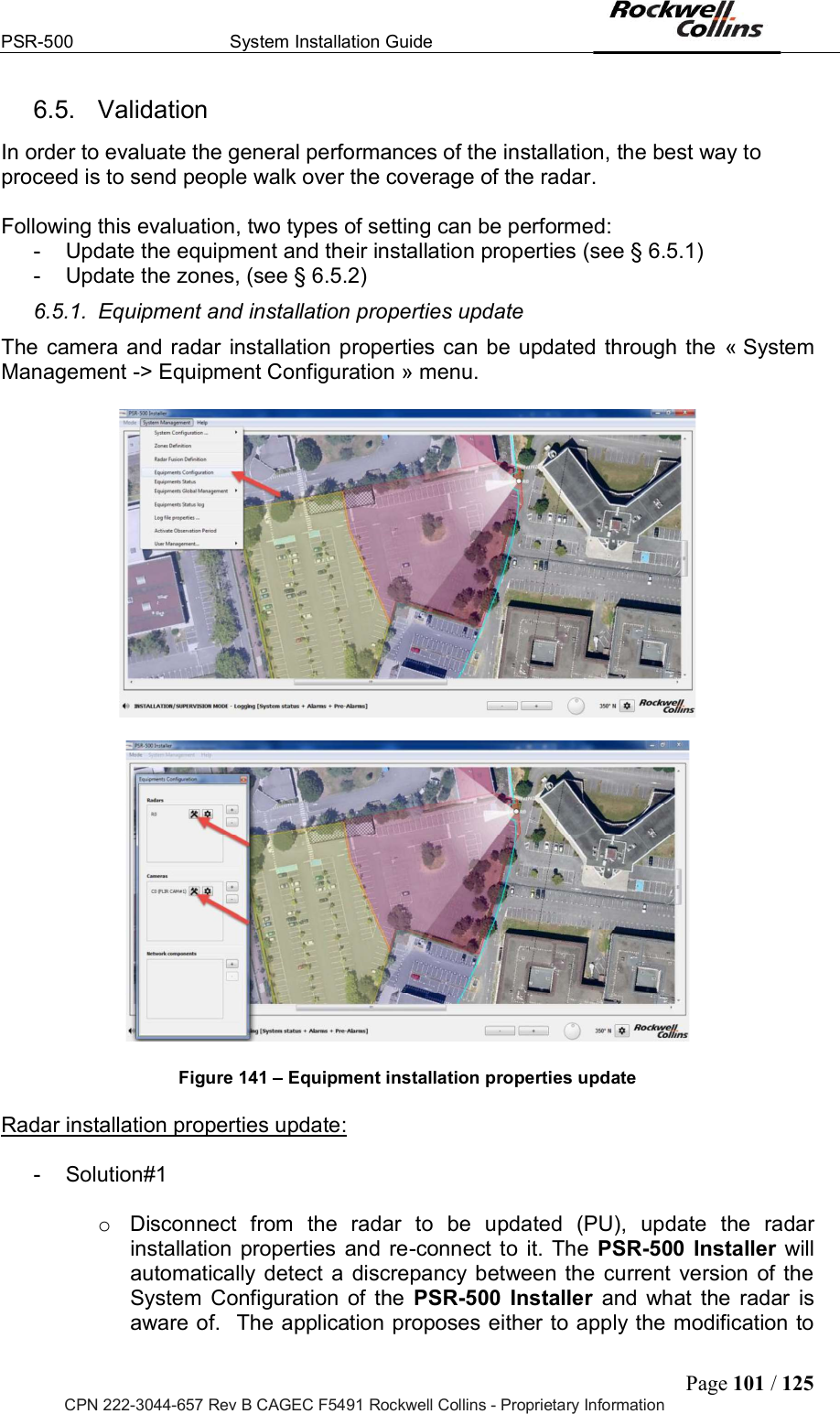
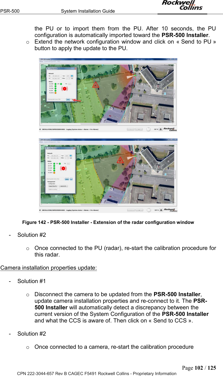
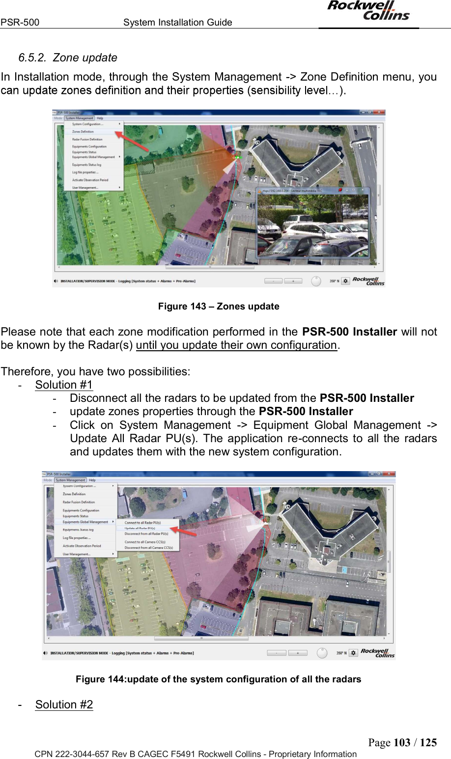
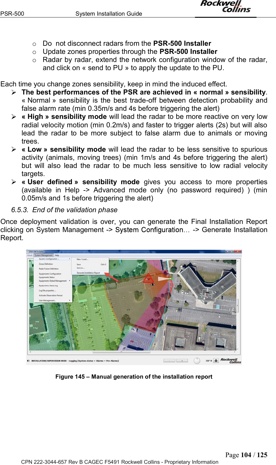
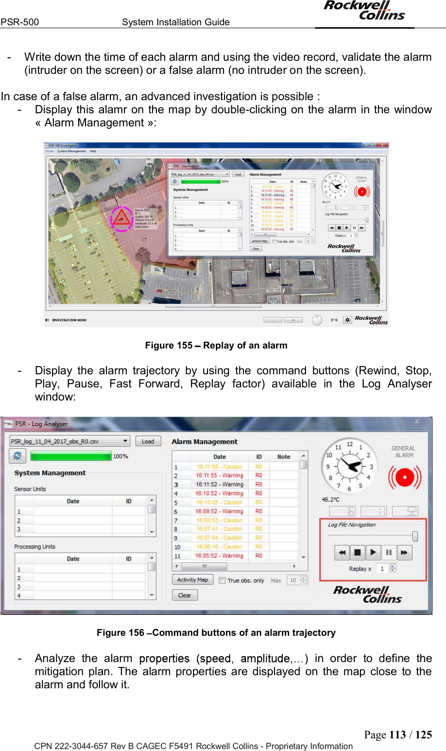
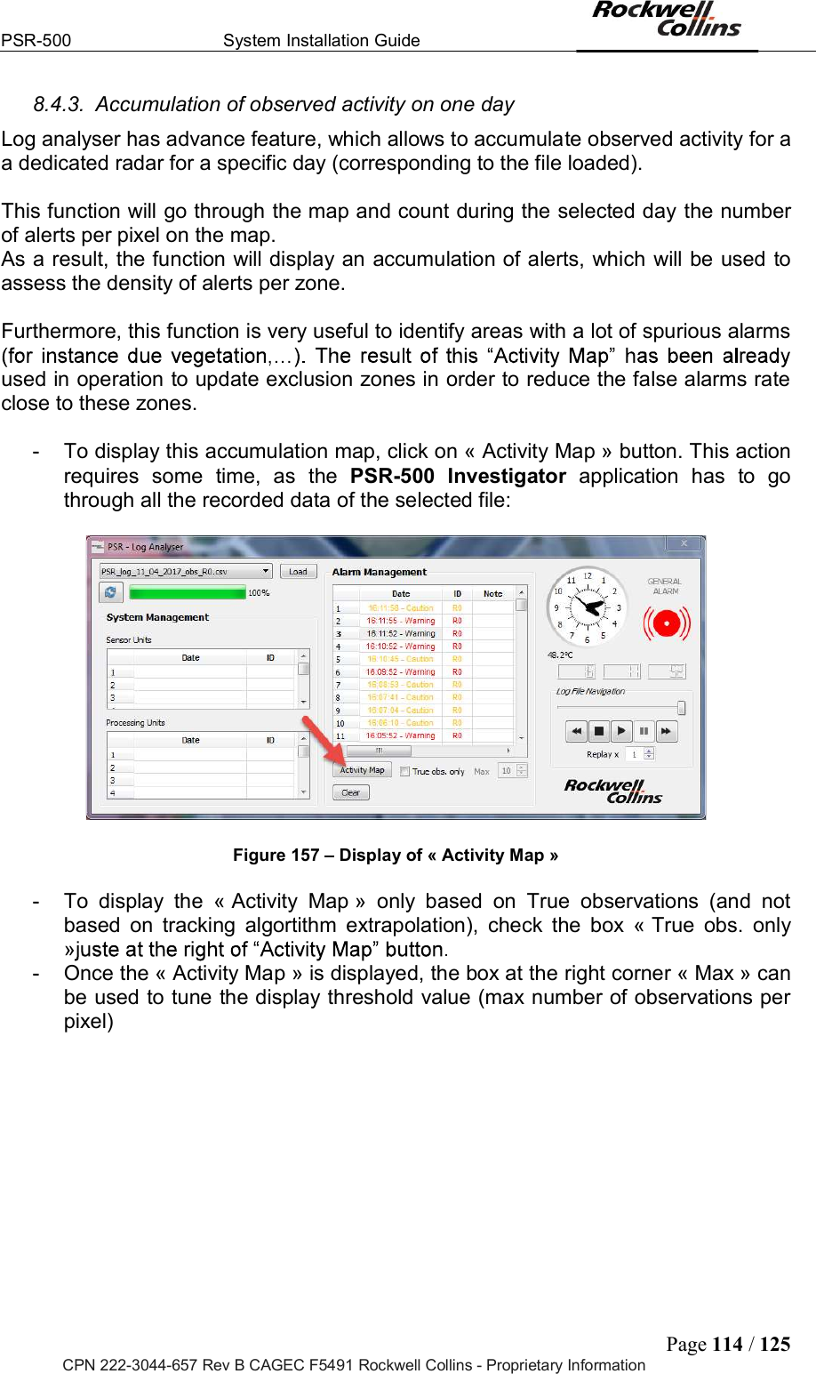
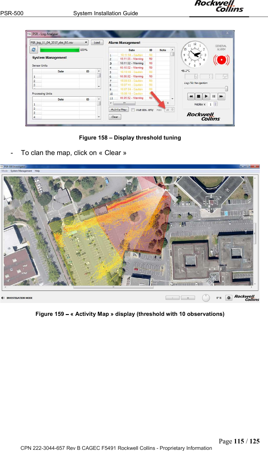
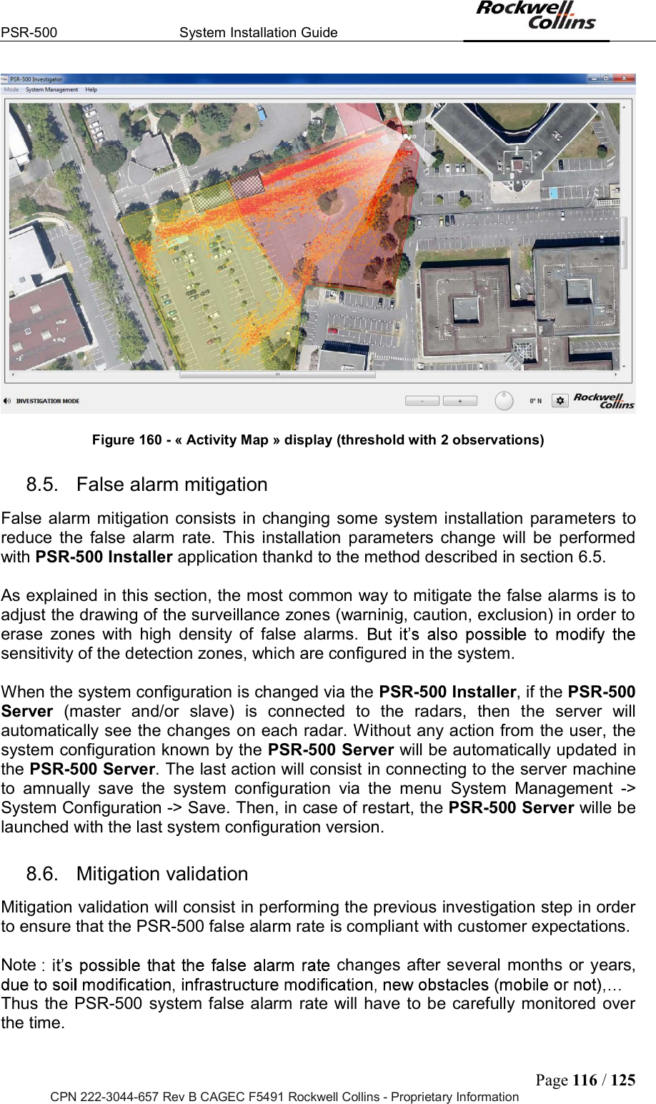
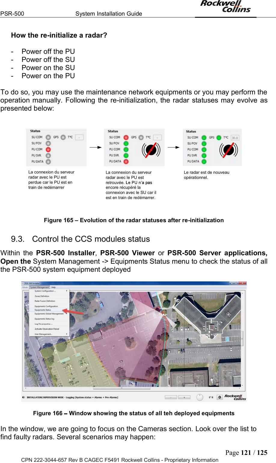
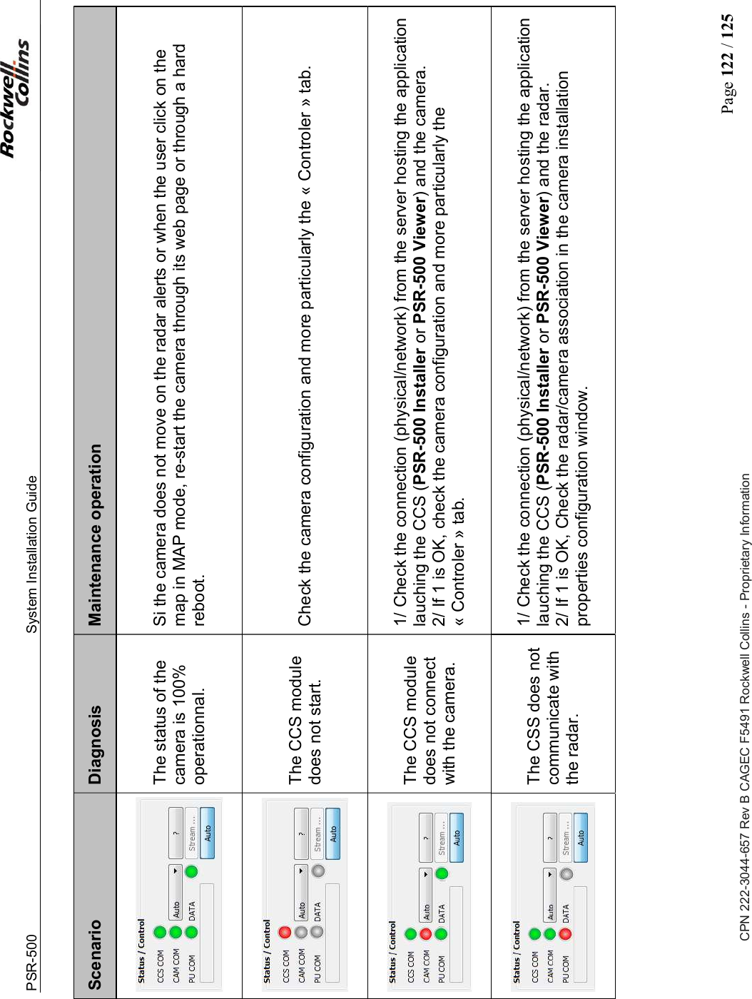
User Manual 101-125