Rockwell Collins 5972410 Perimeter Surveillance Radar User Manual EN 222 3044 657 Installation Guide PSR 500
Rockwell Collins Inc Perimeter Surveillance Radar EN 222 3044 657 Installation Guide PSR 500
Contents
- 1. User Manual 1-40
- 2. User Manual 41-80
- 3. User Manual 81-100
- 4. User Manual 101-125
User Manual 101-125
PSR-500 System Installation Guide
Page 101 / 125
CPN 222-3044-657 Rev B CAGEC F5491 Rockwell Collins - Proprietary Information
6.5. Validation
In order to evaluate the general performances of the installation, the best way to
proceed is to send people walk over the coverage of the radar.
Following this evaluation, two types of setting can be performed:
- Update the equipment and their installation properties (see § 6.5.1)
- Update the zones, (see § 6.5.2)
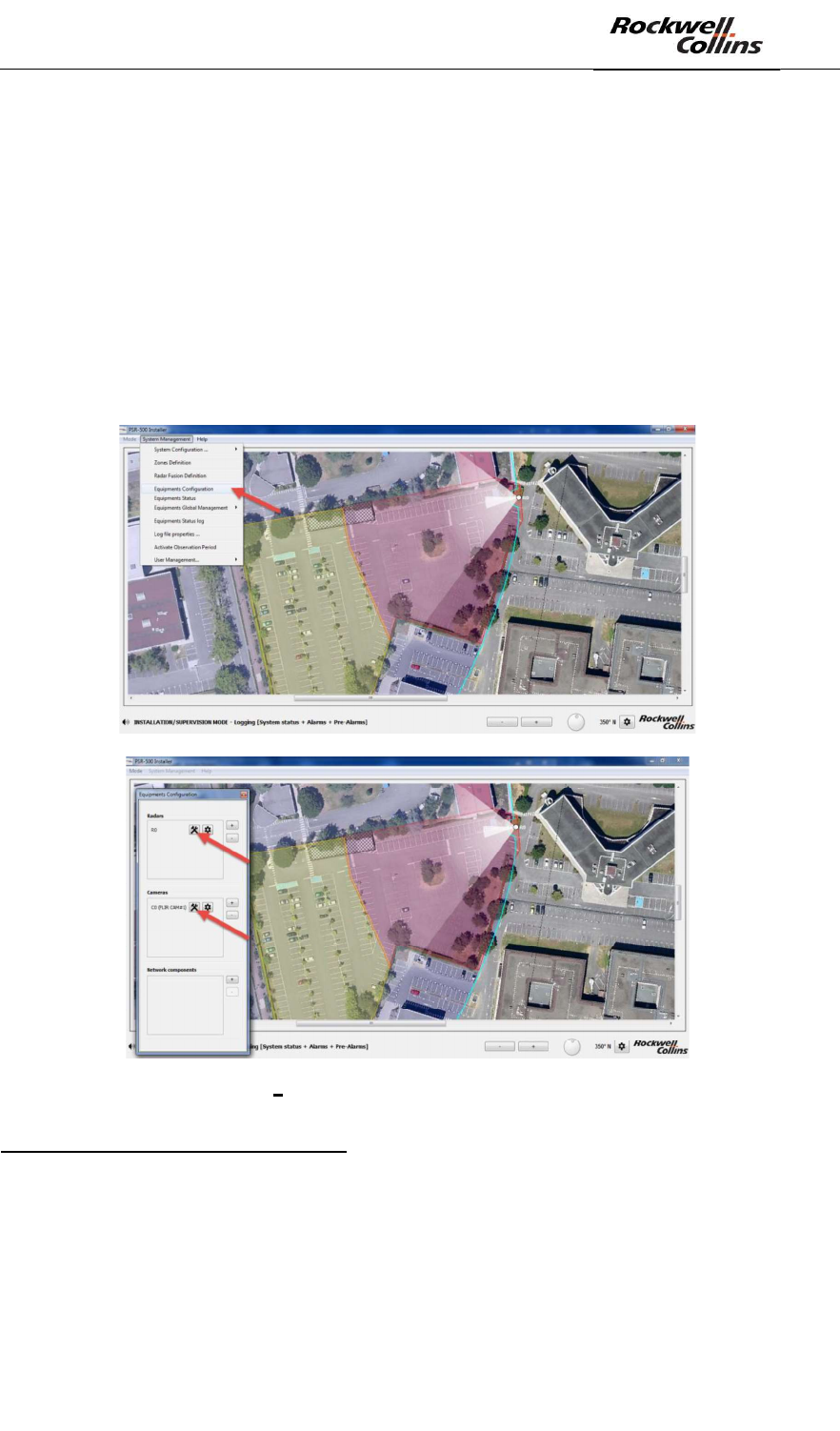
6.5.1. Equipment and installation properties update
The camera and radar installation properties can be updated through the « System
Management -> Equipment Configuration » menu.
Figure 141 Equipment installation properties update
Radar installation properties update:
- Solution#1
o Disconnect from the radar to be updated (PU), update the radar
installation properties and re-connect to it. The PSR-500 Installer will
automatically detect a discrepancy between the current version of the
System Configuration of the PSR-500 Installer and what the radar is
aware of. The application proposes either to apply the modification to
PSR-500 System Installation Guide
Page 102 / 125
CPN 222-3044-657 Rev B CAGEC F5491 Rockwell Collins - Proprietary Information
the PU or to import them from the PU. After 10 seconds, the PU
configuration is automatically imported toward the PSR-500 Installer.
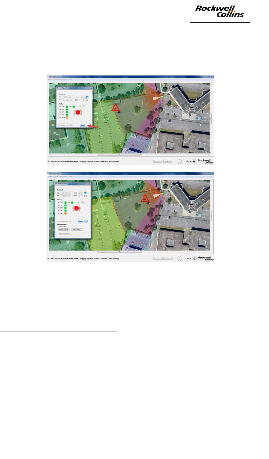
o Extend the network configuration window and click on « Send to PU »
button to apply the update to the PU.
Figure 142 - PSR-500 Installer - Extension of the radar configuration window
- Solution #2
o Once connected to the PU (radar), re-start the calibration procedure for
this radar.
Camera installation properties update:
- Solution #1
o Disconnect the camera to be updated from the PSR-500 Installer,
update camera installation properties and re-connect to it. The PSR-
500 Installer will automatically detect a discrepancy between the
current version of the System Configuration of the PSR-500 Installer
and what the CCS is aware of. Then click on « Send to CCS ».
- Solution #2
o Once connected to a camera, re-start the calibration procedure
PSR-500 System Installation Guide
Page 103 / 125
CPN 222-3044-657 Rev B CAGEC F5491 Rockwell Collins - Proprietary Information
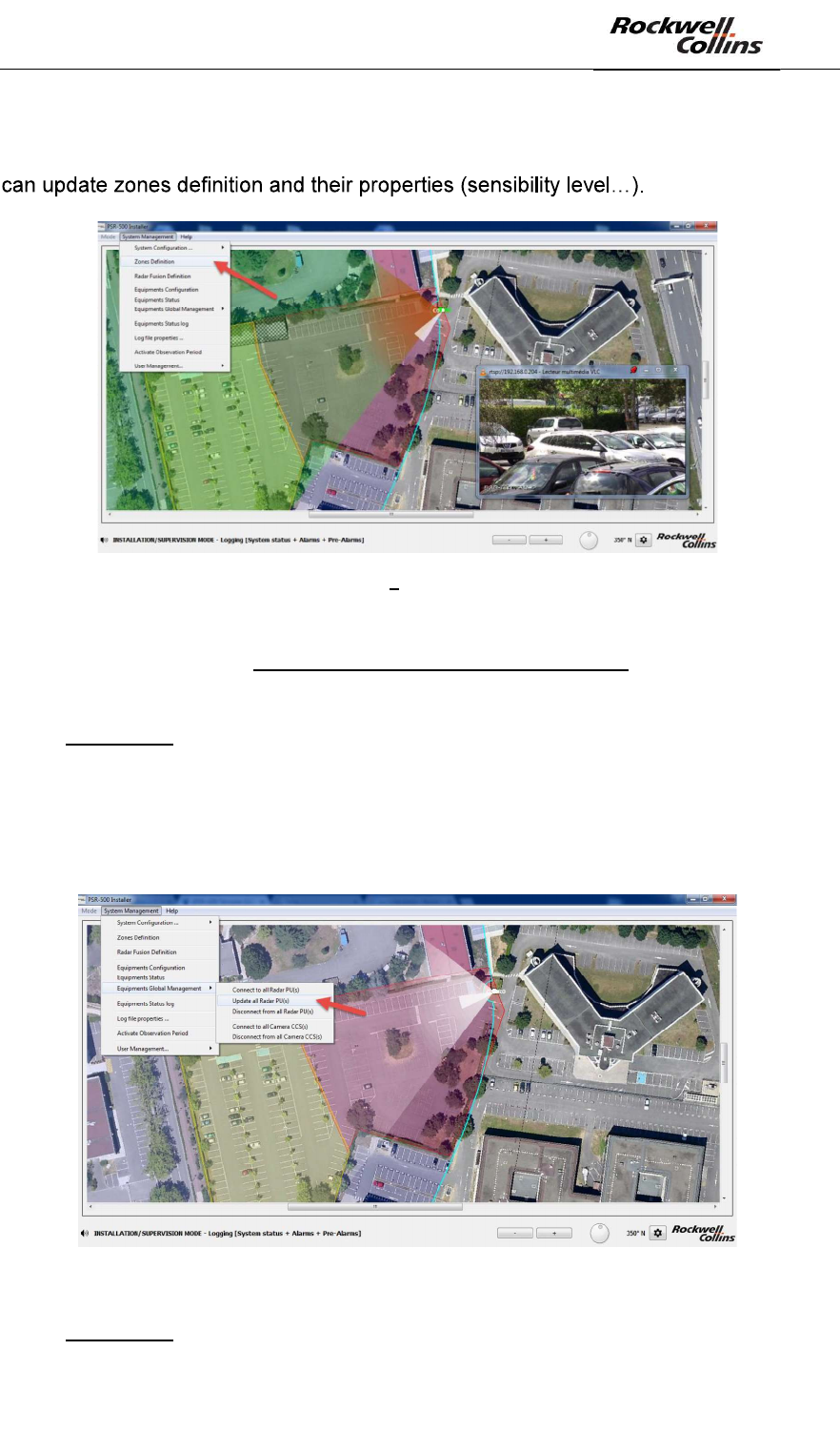
6.5.2. Zone update
In Installation mode, through the System Management -> Zone Definition menu, you
Figure 143 Zones update
Please note that each zone modification performed in the PSR-500 Installer will not
be known by the Radar(s) until you update their own configuration.
Therefore, you have two possibilities:
- Solution #1
- Disconnect all the radars to be updated from the PSR-500 Installer
- update zones properties through the PSR-500 Installer
- Click on System Management -> Equipment Global Management ->
Update All Radar PU(s). The application re-connects to all the radars
and updates them with the new system configuration.
Figure 144:update of the system configuration of all the radars
- Solution #2
PSR-500 System Installation Guide
Page 104 / 125
CPN 222-3044-657 Rev B CAGEC F5491 Rockwell Collins - Proprietary Information
o Do not disconnect radars from the PSR-500 Installer
o Update zones properties through the PSR-500 Installer
o Radar by radar, extend the network configuration window of the radar,
and click on « send to PU » to apply the update to the PU.
Each time you change zones sensibility, keep in mind the induced effect.
The best performances of the PSR are achieved in « normal » sensibility.
« Normal » sensibility is the best trade-off between detection probability and
false alarm rate (min 0.35m/s and 4s before triggering the alert)
« High » sensibility mode will lead the radar to be more reactive on very low
radial velocity motion (min 0.2m/s) and faster to trigger alerts (2s) but will also
lead the radar to be more subject to false alarm due to animals or moving
trees.
« Low » sensibility mode will lead the radar to be less sensitive to spurious
activity (animals, moving trees) (min 1m/s and 4s before triggering the alert)
but will also lead the radar to be much less sensitive to low radial velocity
targets.
« User defined » sensibility mode gives you access to more properties
(available in Help -> Advanced mode only (no password required) ) (min
0.05m/s and 1s before triggering the alert)
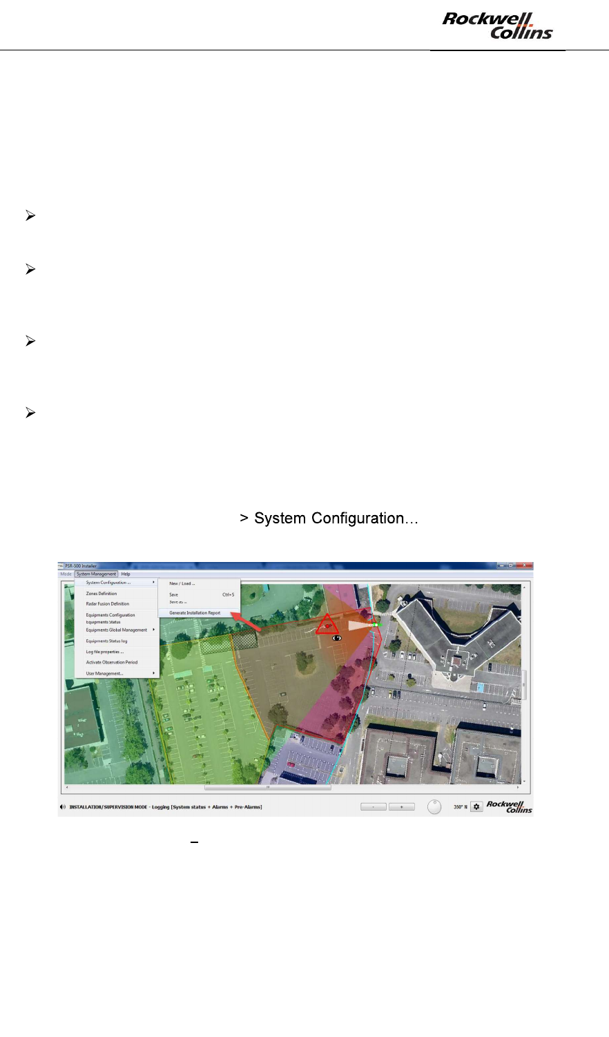
6.5.3. End of the validation phase
Once deployment validation is over, you can generate the Final Installation Report
clicking on System Management - -> Generate Installation
Report.
Figure 145 Manual generation of the installation report
PSR-500 System Installation Guide
Page 105 / 125
CPN 222-3044-657 Rev B CAGEC F5491 Rockwell Collins - Proprietary Information
7.
This chapter is not yet detailed in the English version of the document (please refer
to French version if required).
PSR-500 System Installation Guide
Page 106 / 125
CPN 222-3044-657 Rev B CAGEC F5491 Rockwell Collins - Proprietary Information
8.
System performances optimization is linked with the radar technology concepts,
which were detailed in previous sections of this document.
8.1. Detection capability
8.1.1. Reactivity
The PSR-500 radar maximum reactivity time to trigger an alert (linked to an intrusion)
is 4 seconds.
This performance is achieved if the following conditions are fulfilled:
- The intruder shall be in the detection area covered by the radar
- The intruder shall not be hidden by any obstacles between the radar and him. If
the intruder is partially hidden, then the performances of the radar will be
decreased.
-
account radar location and features of the detection area.
If one of the previous conditions is not fulfilled, then the performances in terms of
reactivity and detection range will be decreased. In this case, radar installation
optimization is required to fulfill these conditions (as detailed in previous sections of
the document).
ind that this reactivity can be localy improved
through tuning of detection zones features.
8.1.2. Localization accuracy
Alert localization accuracy for each radar is directly linked to the quality of the
intruder detection.
The better the detection will be, the most accurate will be the localization accuracy.
As explained before in this document, the localization accuracy is linked to :
- The proximity between the intruder and the radar
- The proximity between the intruder and the boresight of the radar
- No masking area, even partial, between the intruder and the radar
These aspects have to be taken into account when the operating zones are created
(detection or exclusion).
At the edge of the detection range (500m), the test results in a clean environment
(flat zone with pedestrian perfectly visible) show that each radar can localize an
intruder with the following performances:
- Range accuracy: worst case +/-5m whatever the distance between the
intruder and the radar
- Angular accuracy: worst case +/-15m @500m (i.e.: +/-
bear in mind that this accuracy gets better as the intruder comes closer to the
radar.
PSR-500 System Installation Guide
Page 107 / 125
CPN 222-3044-657 Rev B CAGEC F5491 Rockwell Collins - Proprietary Information
8.1.3. Effect of the outside temperature
Outside temperature has a direct effect on the detection performances of a radar.
The colder it will be, the more sensitive the radar will be. Indeed, when the outside
temperature increases, the internal noise of the radar reception chains increases as
well and the efficiency of the amplifiers decreases. Thus the impact of this
phenomenon is a reduction of the radar sensitivity.
As a conclusion, outside temperature has a direct effect on the reactivity and the
localization accuracy of the radar.
8.2. False alarm
The performances of an « active » surveillance sensor are defined by its detection
rate and its false alarm rate.
Each radar of PSR-500 system is preset to reach optimum performances, i.e.: to
ensure the best trade-off between detection sensitivity and false alarm.
Nevertheless, radar system performances can vary depending on the environment
ployed:
-
- Vegetation (
-
- Seasons and meteorological conditions (temperature, humidity
The performances of each radar have to be monitored for each deployment and also
in operation.
Indeed, the real value of a radar false alarm rate can not be calculated in a very short
time. Usually the false alarm rate of a radar is defined by the number of false alarms
per hour or per day of operation. In order to validate that the false alarm rate is in line
with customer expectation, the radar will have to operate during several days.
Various meteorological conditions are necessary during the observation period of the
radar in order to optimize the performances. For instance, it could be useful to focus
on days where the weather conditions were bad.
Performances optimization will need to investigate non-detections or potential false
alarms and system configuration update could be performed as weel (i.e. : features
of operating zones).
not without visual confirmation. If the operator is not there during the false alarm
analysis phase, then access to recorded video stream from cameras (installed on the
site) will be mandatory for visual check and doubt removal.
PSR-500 System Installation Guide
Page 108 / 125
CPN 222-3044-657 Rev B CAGEC F5491 Rockwell Collins - Proprietary Information
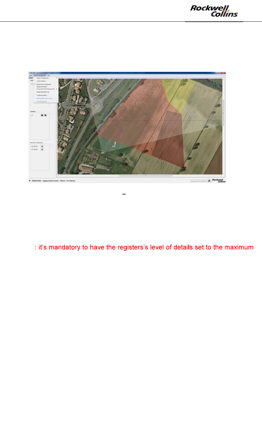
8.3. Observation period activation
To activate the observation period, click on System Management -> Activate
Observation Period:
Figure 146: PSR-500 Server Observation period activation
In this phase, each radar will transmit to the PSR-500 Server all detailed information
on the observed alerts.
The PSR-500 Server will then permanently record all the data, which will be used by
the operator/installer to check the performances of each radar.
WARNING
value, i.e. : « Statuts + Radar data (Alarms + Pre-alarms) ».
WARNING : minimum hard disk space is required when observation period is
activated.
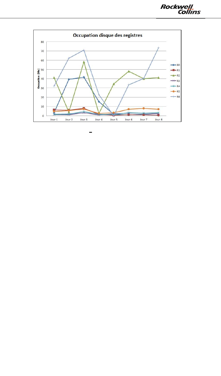
In average,
The recorded data from a radar when the observation period activated is
around 15Mo/day in average. The size of the memory will depend on the activity
observed in front of the radar.
The graph below shows an example of hard disk memory space used on a site
where 7 radars were deployed and in operation during 8 days:
PSR-500 System Installation Guide
Page 109 / 125
CPN 222-3044-657 Rev B CAGEC F5491 Rockwell Collins - Proprietary Information
Figure 147 Memory register analysis
When the observation period is activated, the system shall operate during at least
24h.
8.4. Investigation
As previously explained, when the observation period is activated, the PSR-500
Server continuously records detailed information of all the alerts observed by each
radar.
The PSR-500 Investigator will allow to go through all the registers of each radar and
retrieve relevant information by :
- Displaying the list of recorded alarms
- Showing on the site map the movement of the intrusion alerts.
To use the recorded data by the PSR-500 Server, some files transfer will have to be
performed in the PSR-500 Investigator.
To do so :
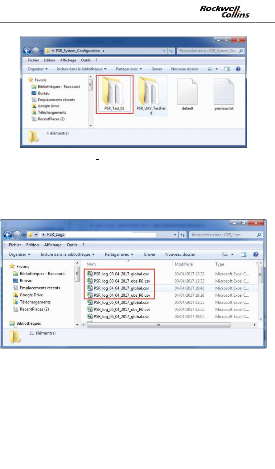
- Copy/Paste the system configuration folder from repository
/PSR_System_Configuration of the PSR-500 Server (or PSR-500 Installer)
to the repository /PSR_System_Configuration of the PSR-500 Investigator
PSR-500 System Installation Guide
Page 110 / 125
CPN 222-3044-657 Rev B CAGEC F5491 Rockwell Collins - Proprietary Information
Figure 148 System configuration folder transfer
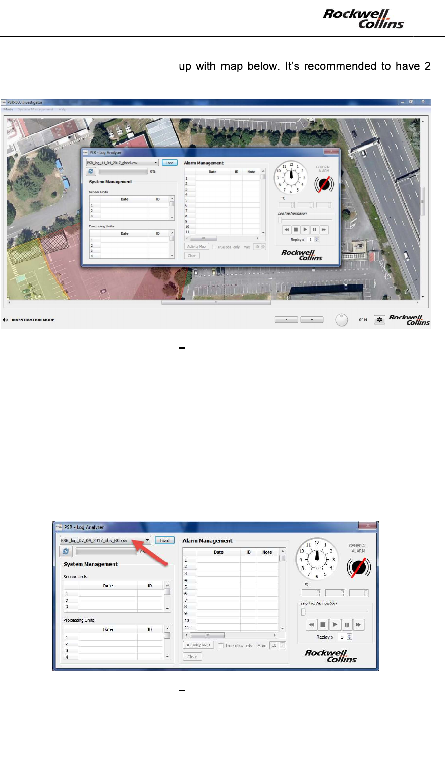
- Retrieve relevant files corresponding to the days and radar of interest in the
folder /PSR_Logs of the PSR-500 Server and transfer these files to the folder
/PSR_Logs of the PSR-500 Investigator. The example below shows the status
system (global) files retrieval of radar R0 corresponding to the days of 3 and 4
April 2017.
Figure 149 Activity files retrieval
- Start the PSR-500 Investigator
- Load the system configuration, which was just prepared by the PSR-500
Installer
- The application knows that the system configuration was prepared by another
application and/or another PC, soi t asks the user to locate the map on this new
application. To do that, go to the folder /PSR_Background_Maps/ of the
application PSR-500 Investigator
PSR-500 System Installation Guide
Page 111 / 125
CPN 222-3044-657 Rev B CAGEC F5491 Rockwell Collins - Proprietary Information
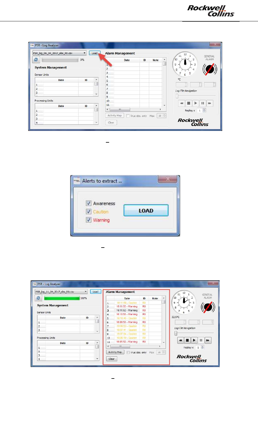
The register analysis window pop-
screens to perform register analysis.
Figure 150 Regsiter analysis window
8.4.1. Register loading
- Open the file corresponding to the day when the false alarms have to be
analyzed
o To select an observation file containing the alerts corresponding to the
radar Rx at the date of dd/mm/yyyy, click on the the drop-down list and
select the file PSR_log_dd_mm_yyyy_obs_Rx.csv
o To select an observation file containing the system status of all the PSR-
500 equipment at the date of dd/mm/yyyy, click on the the drop-down list
and select the file PSR_log_jj_nn_aaaa_global.csv
Figure 151 Observation file selection
- Click on « Load »
PSR-500 System Installation Guide
Page 112 / 125
CPN 222-3044-657 Rev B CAGEC F5491 Rockwell Collins - Proprietary Information
Figure 152 Observation file loading
- If the loaded file is a file containing alerts for a dedicated radar, then a window
will appear to select the level of alerts to retrieve (Awareness and/or Caution
and/or Warning) => then click on « LOAD » button.
Figure 153 Window of alerts to retrieve
- After a certain amount of loading time (depending on the density of the activity at
the selected date), all the alerts will appear in the « Alarm Management »
window:
Figure 154 Display of alerts file
8.4.2. Replay of a single alarm
- Open the video record of the camera associated to the radar under investigation
PSR-500 System Installation Guide
Page 113 / 125
CPN 222-3044-657 Rev B CAGEC F5491 Rockwell Collins - Proprietary Information
- Write down the time of each alarm and using the video record, validate the alarm
(intruder on the screen) or a false alarm (no intruder on the screen).
In case of a false alarm, an advanced investigation is possible :
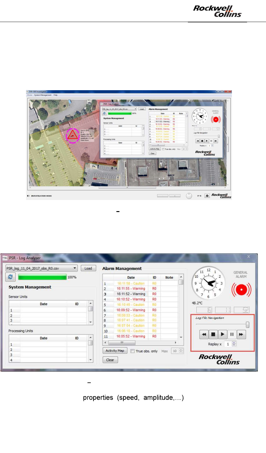
- Display this alamr on the map by double-clicking on the alarm in the window
« Alarm Management »:
Figure 155 Replay of an alarm
- Display the alarm trajectory by using the command buttons (Rewind, Stop,
Play, Pause, Fast Forward, Replay factor) available in the Log Analyser
window:
Figure 156 Command buttons of an alarm trajectory
- Analyze the alarm in order to define the
mitigation plan. The alarm properties are displayed on the map close to the
alarm and follow it.
PSR-500 System Installation Guide
Page 114 / 125
CPN 222-3044-657 Rev B CAGEC F5491 Rockwell Collins - Proprietary Information
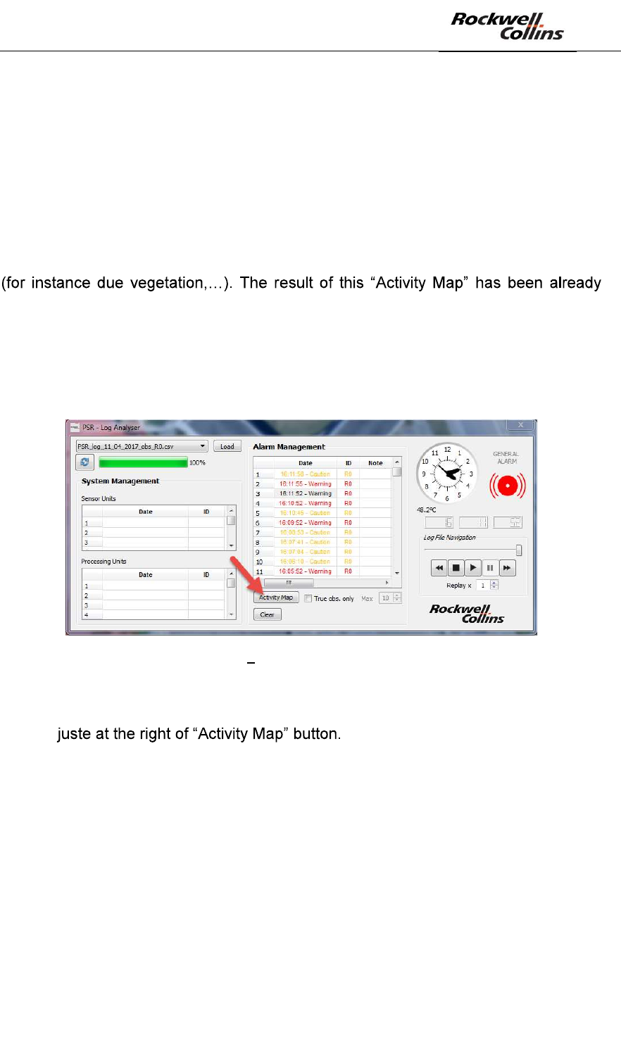
8.4.3. Accumulation of observed activity on one day
Log analyser has advance feature, which allows to accumulate observed activity for a
a dedicated radar for a specific day (corresponding to the file loaded).
This function will go through the map and count during the selected day the number
of alerts per pixel on the map.
As a result, the function will display an accumulation of alerts, which will be used to
assess the density of alerts per zone.
Furthermore, this function is very useful to identify areas with a lot of spurious alarms
used in operation to update exclusion zones in order to reduce the false alarms rate
close to these zones.
- To display this accumulation map, click on « Activity Map » button. This action
requires some time, as the PSR-500 Investigator application has to go
through all the recorded data of the selected file:
Figure 157 Display of « Activity Map »
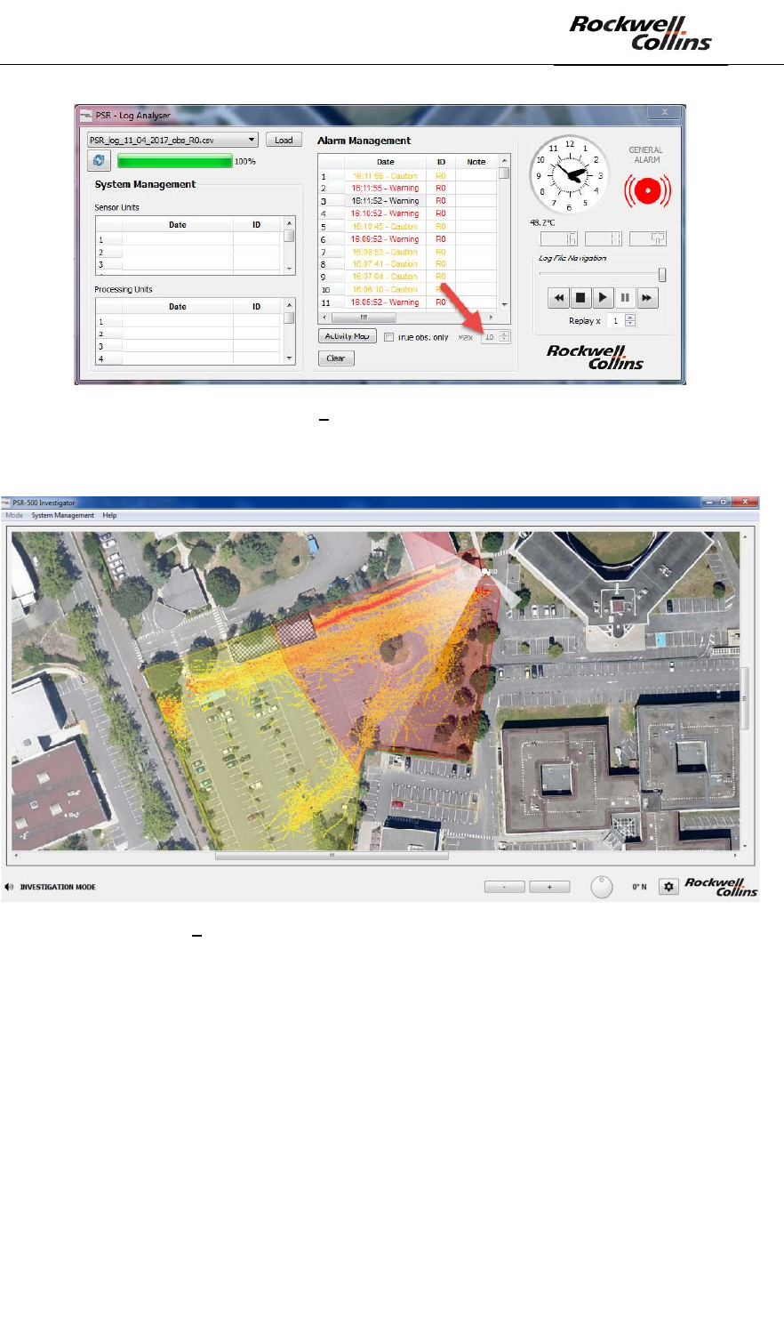
- To display the « Activity Map » only based on True observations (and not
based on tracking algortithm extrapolation), check the box « True obs. only
»
- Once the « Activity Map » is displayed, the box at the right corner « Max » can
be used to tune the display threshold value (max number of observations per
pixel)
PSR-500 System Installation Guide
Page 115 / 125
CPN 222-3044-657 Rev B CAGEC F5491 Rockwell Collins - Proprietary Information
Figure 158 Display threshold tuning
- To clan the map, click on « Clear »
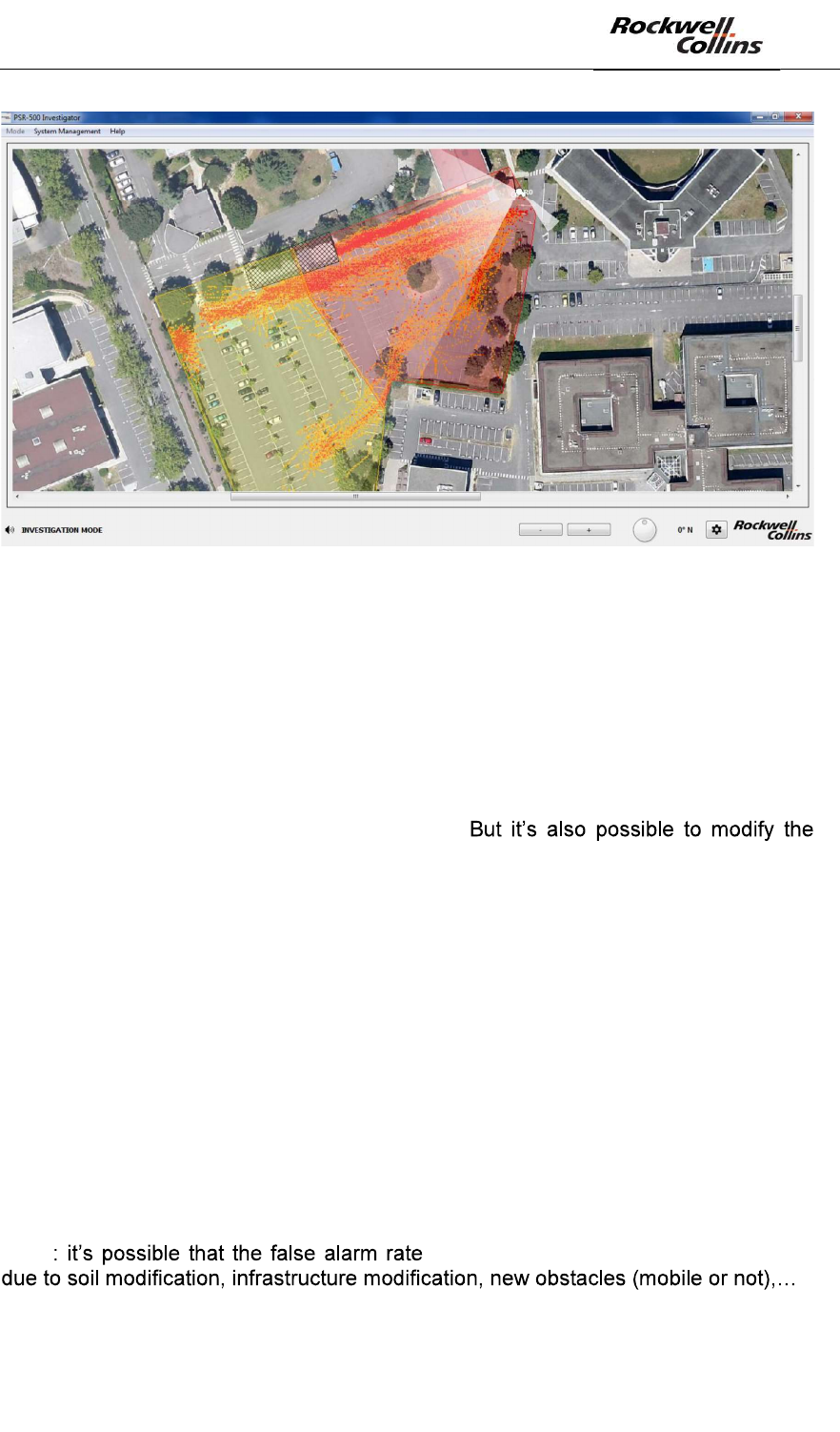
Figure 159 « Activity Map » display (threshold with 10 observations)
PSR-500 System Installation Guide
Page 116 / 125
CPN 222-3044-657 Rev B CAGEC F5491 Rockwell Collins - Proprietary Information
Figure 160 - « Activity Map » display (threshold with 2 observations)
8.5. False alarm mitigation
False alarm mitigation consists in changing some system installation parameters to
reduce the false alarm rate. This installation parameters change will be performed
with PSR-500 Installer application thankd to the method described in section 6.5.
As explained in this section, the most common way to mitigate the false alarms is to
adjust the drawing of the surveillance zones (warninig, caution, exclusion) in order to
erase zones with high density of false alarms.
sensitivity of the detection zones, which are configured in the system.
When the system configuration is changed via the PSR-500 Installer, if the PSR-500
Server (master and/or slave) is connected to the radars, then the server will
automatically see the changes on each radar. Without any action from the user, the
system configuration known by the PSR-500 Server will be automatically updated in
the PSR-500 Server. The last action will consist in connecting to the server machine
to amnually save the system configuration via the menu System Management ->
System Configuration -> Save. Then, in case of restart, the PSR-500 Server wille be
launched with the last system configuration version.
8.6. Mitigation validation
Mitigation validation will consist in performing the previous investigation step in order
to ensure that the PSR-500 false alarm rate is compliant with customer expectations.
Note changes after several months or years,
Thus the PSR-500 system false alarm rate will have to be carefully monitored over
the time.
PSR-500 System Installation Guide
Page 117 / 125
CPN 222-3044-657 Rev B CAGEC F5491 Rockwell Collins - Proprietary Information
9.
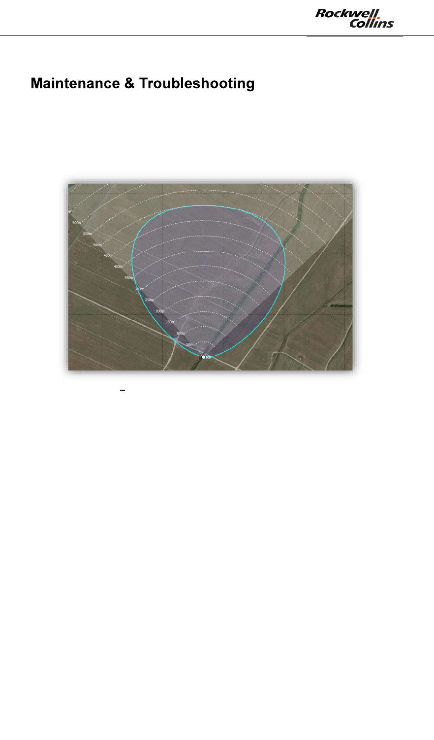
9.1. Display of the radar covering area
After creation of a new system configuration and in particular the addition of a new
radar with the PSR-500 Installer, the shape of the radar covering area shall be
displayed as below:
Figure 161 Nominal shape of the PSR-500 radar covering area
If the shape is different, then the final performances of the PSR-500 system will
be impacted.
The map referencing was not correctly performed. Perhaps the geographical
localization was inverted (latitude/longitude) or the coma was not well placed. In this
case, the creation of the system configuration shall be performed again, starting from
the beginning.
Indeed, the map referencing and its accuracy are the key points to ensure system
performances.
9.2. Control the status of the deployed radars
Each radar of the PSR-500 system is monitored by maintenance network
components (if they are deployed, configured and tested as explained in this guide)
through the « master » PSR-500 Server.
In case of abnormal operation, the automatic maintenance is launched.
Nevertheless, it may occur operational scenario where the automatic maintenance
can not solve the problem.
Be carreful, if an operator needs to perform a maintenance operation of a radar, the
PSR-500 Server (master and slave) shall be disconnected from this radar to avoid
PSR-500 System Installation Guide
Page 118 / 125
CPN 222-3044-657 Rev B CAGEC F5491 Rockwell Collins - Proprietary Information
that the automatic maintenance takes the control of the associated network
equipments during the maintenance operation.
In any case (automatic maintenance or not), it is needed that the operator is able to
control the deployed radars and to diagnose an eventual failure.
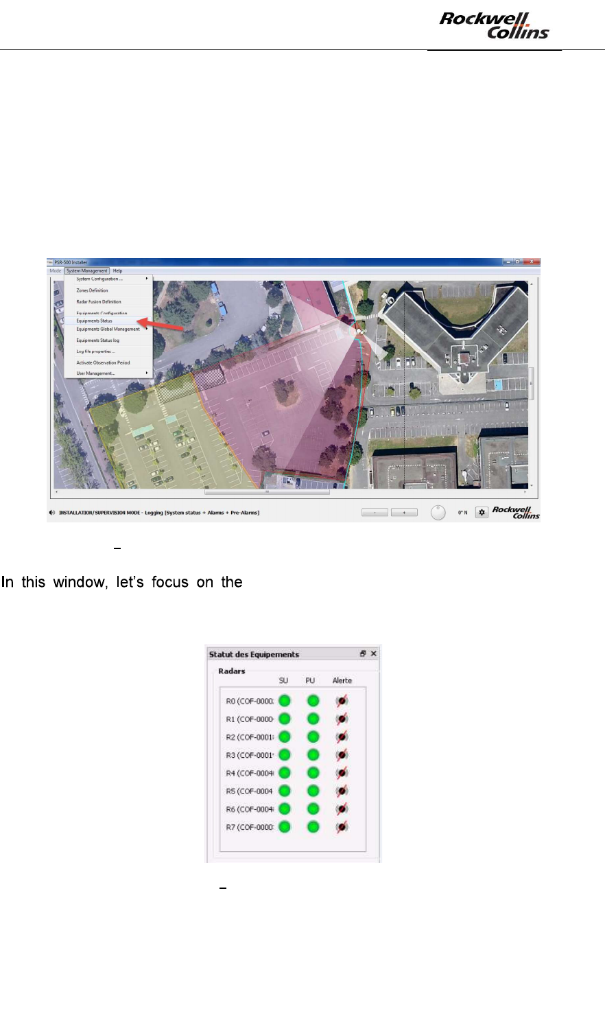
Within the PSR-500 Installer, PSR-500 Viewer or PSR-500 Server applications, the
status of all deployed equipement can be seen by opening the System Management
-> Equipments Status menu:
Figure 162 Opening the window to check the status of all deployed equipments
« Radars » section. The statuses are indicated
radar by radar, for its SU and its SU. The Alerte status indicated the alert state of this
radar. The following picture presents an extract of this report.
Figure 163 Extract related to the radar status
- Scan the list to find any radar in failure. Several scenarios may happen :
PSR-500 System Installation Guide
Page 119 / 125
CPN 222-3044-657 Rev B CAGEC F5491 Rockwell Collins - Proprietary Information
Scenario Diagnosis
Nothing to Report. The radar is 100% operational.
The radar is in default.
The PU is facing a problem and can not communicate with the SU.
See below.
The radar is in default.
The radar is facing a problem to get access to the PU.
See below.
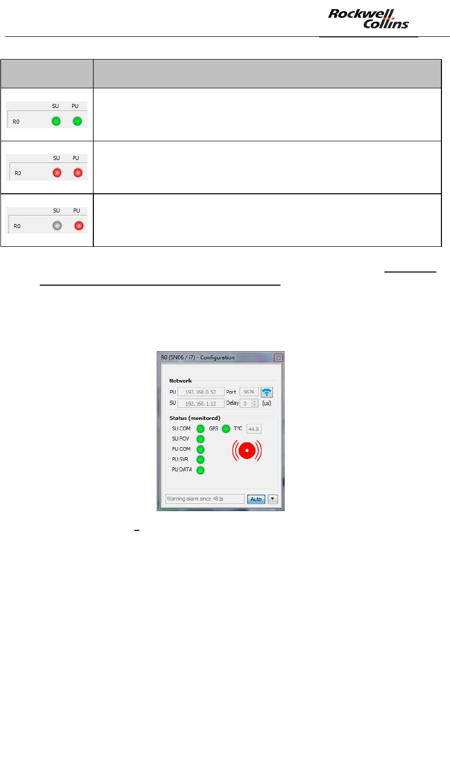
- When a radar is identified as in default, click on one of its indicators in order to
identify precisely the exact reason of the defect.
- A new window opens giving acces to the detailed status of the radar. This is
the network component properties configuration that we already used during
the installation. This window contains also all the status associated with this
radar.
Figure 164 Radar network properties configuration window
- Several scenario may occur:
PSR-500 System Installation Guide
Page 120 / 125
CPN 222-3044-657 Rev B CAGEC F5491 Rockwell Collins - Proprietary Information
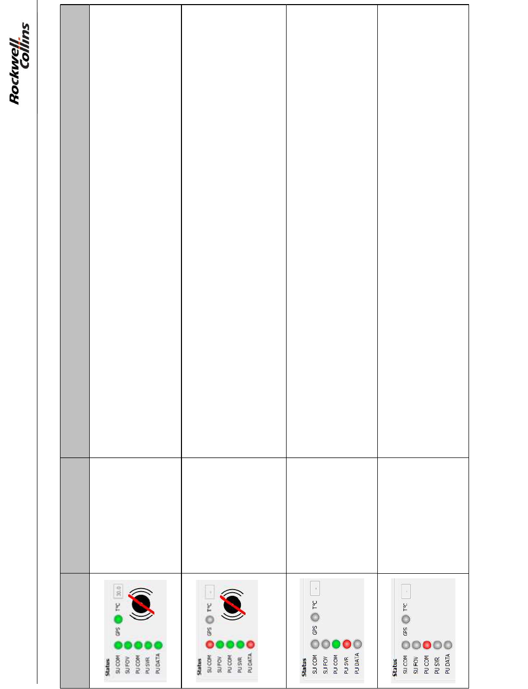
Scenario Diagnosis Maintenance operation
The associated
radar is 100%
operationnal.
Nothing to Report.
The radar has a
problem with the
radar antenna (SU).
1/ Re- initialize the radar (see below)
2/ If 1 is OK, check the link between the SU and the PU
3/ If 1+2 is OK, check is the SU is correctly powered
4/ If 1+2+3 is OK, change the SU
The radar has a
problem with its PU.
1/ Re-initialize the radar
The radar server
can not
communicate with
the PU.
1/ Check the link between the radar and the application used for the diagnosis
2/ If 1 is OK, check that the PU is powered and up
3/ If 1+2 is OK, control the PU power supply
4/ If 1+2+3 is OK, replace the PU
PSR-500 System Installation Guide
Page 121 / 125
CPN 222-3044-657 Rev B CAGEC F5491 Rockwell Collins - Proprietary Information
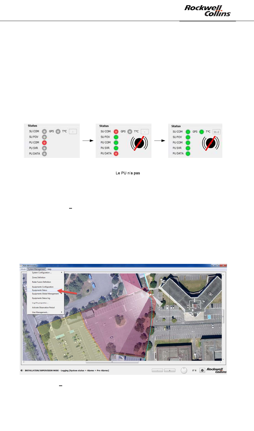
How the re-initialize a radar?
- Power off the PU
- Power off the SU
- Power on the SU
- Power on the PU
To do so, you may use the maintenance network equipments or you may perform the
operation manually. Following the re-initialization, the radar statuses may evolve as
presented below:
La connexion du serveur
radar avec le PU est
perdue car le PU est en
train de redémarrer
La connexion du serveur
radar avec le PU est
retrouvée.
encore récupéré la
connexion avec le SU car il
est en train de redémarrer.
Le radar est de nouveau
opérationnel.
Figure 165 Evolution of the radar statuses after re-initialization
9.3. Control the CCS modules status
Within the PSR-500 Installer, PSR-500 Viewer or PSR-500 Server applications,
Open the System Management -> Equipments Status menu to check the status of all
the PSR-500 system equipment deployed
Figure 166 Window showing the status of all teh deployed equipments
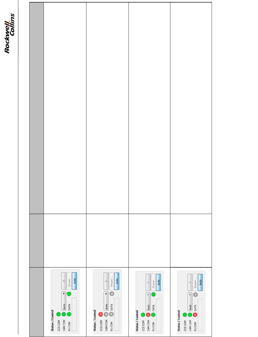
In the window, we are going to focus on the Cameras section. Look over the list to
find faulty radars. Several scenarios may happen:
PSR-500 System Installation Guide
Page 122 / 125
CPN 222-3044-657 Rev B CAGEC F5491 Rockwell Collins - Proprietary Information
Scenario Diagnosis Maintenance operation
The status of the
camera is 100%
operationnal.
Si the camera does not move on the radar alerts or when the user click on the
map in MAP mode, re-start the camera through its web page or through a hard
reboot.
The CCS module
does not start. Check the camera configuration and more particularly the « Controler » tab.
The CCS module
does not connect
with the camera.
1/ Check the connection (physical/network) from the server hosting the application
lauching the CCS (PSR-500 Installer or PSR-500 Viewer) and the camera.
2/ If 1 is OK, check the camera configuration and more particularly the
« Controler » tab.
The CSS does not
communicate with
the radar.
1/ Check the connection (physical/network) from the server hosting the application
lauching the CCS (PSR-500 Installer or PSR-500 Viewer) and the radar.
2/ If 1 is OK, Check the radar/camera association in the camera installation
properties configuration window.

PSR-500 System Installation Guide
Page 123 / 125
CPN 222-3044-657 Rev B CAGEC F5491 Rockwell Collins - Proprietary Information
9.4. Control the status of the data flow that cames out of the PSR-
500 Server
The external client does not receive or does not receive anymore any message from
the PSR-500 Server:
- Launch the test with the local web page on the server hosting the PSR-500
Server application (see section Erreur ! Source du renvoi introuvable.).
Does the web page receive some CONFIG, STATUS, ALERTS or
CAM_TRACKING_ACTIVITY messages?
o Yes = the reception is thus possible locally by not remotly which may be
due to a firewall problem Authorized the PSR-500 application in the
Windows firewall settings. (see section Erreur ! Source du renvoi
ntrouvable.)
o No = the reception is not possible locally
Case 1 = the answer FAILED is received during the
authentification check the user name and the password used
to connect to the PSR-500 Server. Have they been correctly
created in the PSR-500 Server?
Case 2 = no answer is displayed
Is the server module of the PSR-500 Server activated?
o No = activate it
o Yes = contact the support
9.5. Control the radar and/or camera alignment status
If the intruder is not correclt positionned on the background map:
- Control the calibration of the radar
- Control the map georeferencing
If the intruder is not correctly centered in the image:
- Control the calibration of the radar
- Control the calibration of the camera
o Warning: Some COTS camera may drift afert a certain perdio of
operation. Before modifying the calibration properties of a camera, it is
recommended to first re-start the camera.
o The CCS module assumes that the terrain on which the PSR-500 is
deployed is falt. If the terrain presents some relief (is not falt), since the
CCS does not take in into account, the radar alert may not be well
positionned dependning on the distance from the camera.

PSR-500 System Installation Guide
Page 124 / 125
CPN 222-3044-657 Rev B CAGEC F5491 Rockwell Collins - Proprietary Information
10.
10.1. Quick Installation Guide for the PSR-500
This guide is intended to be used as an installation checklist for a seasoned
installation operator of the PSR-500 system. It is recommanded to a new user to read
the entire system installation document in order to get familiar with the concets and
operations described in the document.
- Step 1 = Prepare the deployment system configuration with the PSR-500
Installer
o Load and reference the background map
o Define operating zone for the radars
o Add, pre-position the radars and configure the network addresses
o In option
Add, pre-position the cameras and configure the network
addresses
Add and configure the maintenance network components
o Generate the preliminary installation report
o Perform a visit of the site and validate/update the installation
o Add installation operators (if needed)
- Step 2 = Install physically and start the radars
- Step 3 = Define and validate the radar interoperability strategy
- Step 4 = Align the radars and the cameras
- Step 5 = Validate/update the installation and generate the final installation report
- Step 6 = Deploy the PSR-500 Server on the « master » host
o Transfer the system configuration as well as the background map
prepared from the PSR-500 Installer toward the PSR-500 Server
o Start the application and load the system configuration
o Add and activate the server module
o Add user to the server
o Test that the server can be accessed
o Add and configure the master/slave module as « master »
o Save the new system configuration
o Connect to all the equipments
o Activate the observation period
- Step 7 = Deploy the PSR-500 Server on the « slave » host
o Transfer the entire folder from the PSR-500 Server master to the PSR-
500 Server slave ( to retreive the system configuration and the
authorized user list)

PSR-500 System Installation Guide
Page 125 / 125
CPN 222-3044-657 Rev B CAGEC F5491 Rockwell Collins - Proprietary Information
o Start the application and load the system configuration
o Modifiy the configuration of the server module
o Test that the server can be accessed
o Modify the configuration of the master/slave module as « slave »
o Save the new system configuration
o Connect to all equipments
o Activate the observation period
- Step 8 = Investigate/optimize the performances