Rockwell Collins 5972410 Perimeter Surveillance Radar User Manual EN 222 3044 657 Installation Guide PSR 500
Rockwell Collins Inc Perimeter Surveillance Radar EN 222 3044 657 Installation Guide PSR 500
Contents
- 1. User Manual 1-40
- 2. User Manual 41-80
- 3. User Manual 81-100
- 4. User Manual 101-125
User Manual 81-100
PSR-500 System Installation Guide
Page 81 / 125
CPN 222-3044-657 Rev B CAGEC F5491 Rockwell Collins - Proprietary Information
To be sure that the radar that is going to be used as the « spectrum analyzer » does
not see any other radar of the PSR-500 system, we shall set the delay >=40us.
To be able to set « delay », the PSR-500 Installer application shall be disconnected
to the radar.
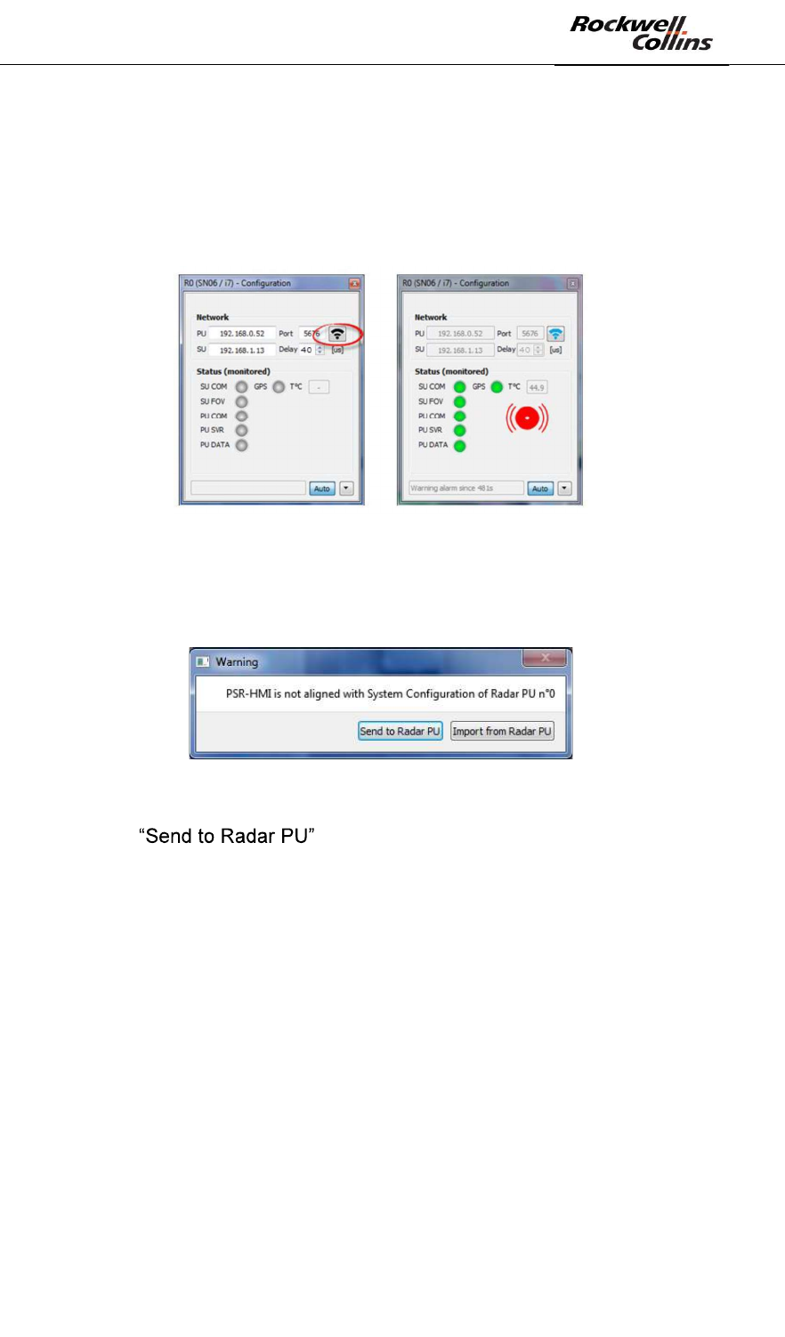
- Once the delay set, click on the button to connect to the PU associated with
the radar :
Figure 113: Connection to the PU of a radar
- Since the delay value has been modified, the PSR-500 Installer application
automatically detect that the PU shall be updated.
- The following window opens automatically.
Figure 114: Configuration alignment window
- Click on to update the PU configuration.
- After few seconds, the PU is updated.
Finally, the following steps shall be followed so that the synchronization instruction is
received and taken into consideration by the SU:
- Power off the PU
- Power off the SU
- Power on the SU
- Power on the PU
The PSR-500 Installer application loses its connection with the radar and retrieves it
after one minute. The radar now has taken into account its new synchronization
instruction.
Note: the AUTO button, on the bottom of the window that allow the connection to the
radar, when checked, enables the application to automatically retry to connect to the
radar every 10 seconds when the connection is lost. If uncheck, this automatic re-
connection is not performed anymore.
PSR-500 System Installation Guide
Page 82 / 125
CPN 222-3044-657 Rev B CAGEC F5491 Rockwell Collins - Proprietary Information
Now that we set the radar delay to a value >= 40us, if the radio environment is clean,
i.e. if there is no jammer in the operating frequency band of the radar, then no
interference shall be received.
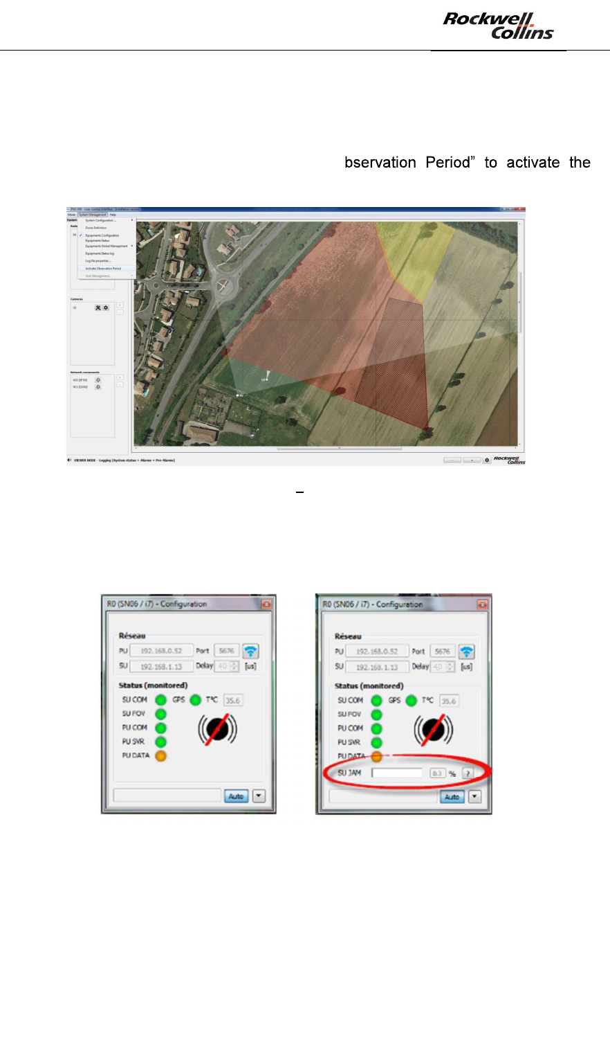
Click on « System Management -> Activate O
observation period.
Figure 115: PSR-500 Installer Activate observation period
- A new gauge appears in the radar configuration window. This gauge indicates
the level of interference received by this radar. When this level is higher than
2%, the SU is jammer.
Figure 116 - "interference" gauge
- The level shall be stable and below 2%
o If this is the case, we can proceed with the radar interoperability setting.
o If this is not the case, it means that there is a jammer in the oepration
frequency band of the PSR-500 radars. It shall be identified and power
down otherwise the PSR-500 system will be ineffective.
PSR-500 System Installation Guide
Page 83 / 125
CPN 222-3044-657 Rev B CAGEC F5491 Rockwell Collins - Proprietary Information
6.3.3. Radar interoperability setting
6.3.3.1. General principle
The minimum « delay » between any two radars is 15us. Nevertheless, if the radars
are installed too close to each other, the value shall be set to a higher value.
In his first system configuration, the operator can start so that all radars are shifted by
15us one to others.
After this first configuration, we then synchronize the radars, validate the predefined
synchronization strategy and possibly modify it.
The operator shall proceed radar by radar:
- Start by a radar whose delay is higher than 40us and then turn on the
deployed radars until ending by the radars whose delay is lower than 40us.
- For each radar, the user shall set the synchronization instruction as described
in the previous chapter and check that no interference is received once
applied.
o If this is the case, go to the next radar.
o If this is not the case, it means that the predefined synchronization
strategy is to optimistic, i.e. that the radar are too closed to each
lay value
where there is no interference anymore.
Note: With the minimum delay of 15us, 40 radars can be operated simultaneously.
Nevertheless, it may be some deployment situation where this delay can be farther
reduced, even be the same if the radars are physically isolated, i.e. two radars on
two sides (north and south) of a same big site. In such a situation, the number of
radars that can operate simultaneously on the same site can be increased.
Note: If a radar is jammed, it means that it is also jamming another one. If a radar is
not jammed, it means that it is not jamming another radar neither.
PSR-500 System Installation Guide
Page 84 / 125
CPN 222-3044-657 Rev B CAGEC F5491 Rockwell Collins - Proprietary Information
6.4. Alignment
Once we reach this step, we consider that the interoperability is configured and
verified. The radars are in nominal operational configuration and are not jamming
has not been correctly configured.
6.4.1. Alignment of a radar
The objective of this step is to update the radar installation properties so that radar
alerts are correctly geo-localized. To do so, we are going to ensure that the positions
of the alerts on the map are in coherence with their real position.
Depending on where was the deployment, you have two options:
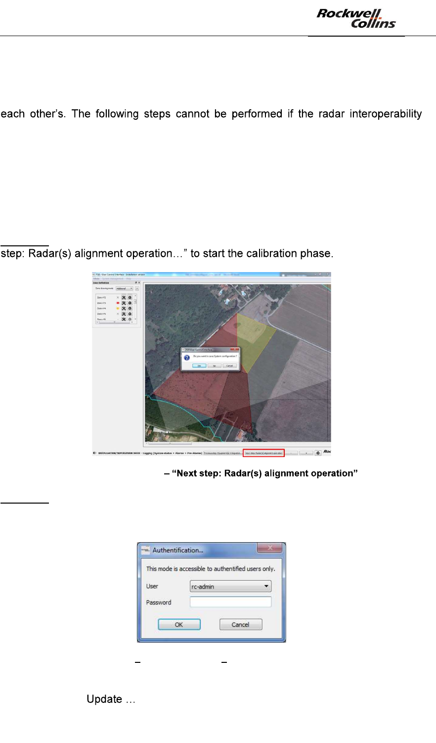
Option #1: the PSR-500 Installer is not closed. Click on the bottom left button « Next
Figure 117: PSR-500 Installer button
Option #2: the PSR-500 Installer is closed.
- Start the PSR-500 Installer application
- The Authentification window opens
Figure 118 PSR-500 Installer Authentification window
- Enter the default password
- Click on « » :
PSR-500 System Installation Guide
Page 85 / 125
CPN 222-3044-657 Rev B CAGEC F5491 Rockwell Collins - Proprietary Information
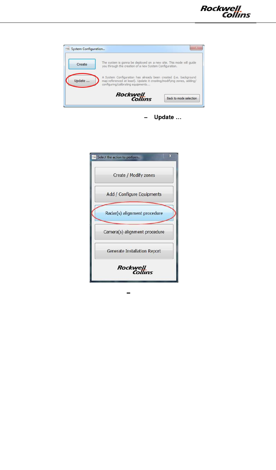
Figure 119: PSR-500 Installer « » button
- Select the System Configuration you would like to update
- Select « Radar(s) alignment procedure »
Figure 120: PSR-500 Installer « Radar(s) alignment procedure »
The following window automatically opens.
PSR-500 System Installation Guide
Page 86 / 125
CPN 222-3044-657 Rev B CAGEC F5491 Rockwell Collins - Proprietary Information
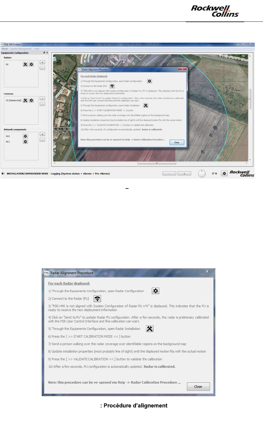
Figure 121: PSR-500 Installer Alignment procedure window
We will now pursue with Option#2.
Note: Option#1 is the same except that at the end of each step, you have the bottom
buttons that guide you to switch to the next phase up to the Final Installation Report
generation.
After clicking on « Radar(s) alignment procedure » button, the following window
appears:
Figure 122 radar
PSR-500 System Installation Guide
Page 87 / 125
CPN 222-3044-657 Rev B CAGEC F5491 Rockwell Collins - Proprietary Information
To perform radar calibration, the operator shall follow the 10 steps described in the
procedure.
The procedure ensures that the alerts raised oar the radar fit with the background
map. For example, if an « intruder » walks along the road, it shall appear along the
same road on the background map. This correlation is essential for the system since
the camera will also be aligned based on the background map. The background map
is the common reference shared by all the sensors of the PSR-500 system.
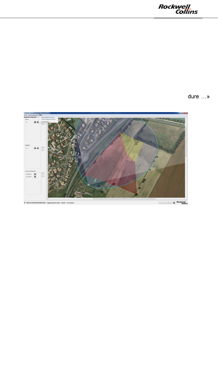
Note: This procedure can be access anytime in the PSR-500 Installer. Click on
« Help » tab on the menu bar and then click on « Radar Calibration Proce ,
cf. following picture:
Figure 123: Radar calibration procedure through the Help menu
Note: this procedure shall be performed for each radar.
Note: It is recommended to use a target with a high reflectivity to align the radar so
that radar mismeasurement does not influence the calibration procedure. A very slow
car or a pedestrian with a reflector are example of a good target. It is also
recommended that the target follow a path that can be easily identifiable on the map.
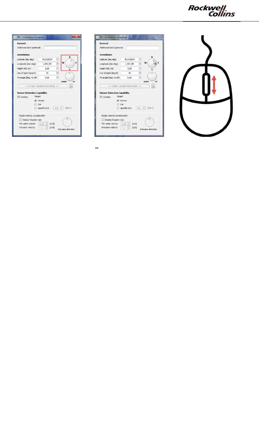
Note: During the calibration phase, when the target is moving on the radar coverage,
it is possible to modify the radar installation properties :
- Move the radar directly on the map if its GPS position is wrong
- Modify its GPS coordinates its height, its line of sight and its tilt directly in the
radar installation properties window (either by entering new values or by using
the arrow to increase or decrease the values step by step).
- Modify its line of sight using the North, East, South, West rotary wheel:
o Click on it, keep it pressed and move the mouse
o Putting the mouse over it and using the mouse scroll (maximum
precision)
PSR-500 System Installation Guide
Page 88 / 125
CPN 222-3044-657 Rev B CAGEC F5491 Rockwell Collins - Proprietary Information
Figure 124 Handling during radar alignment
- The same handling scan be use to adjust the radar tilt with the DOWN/UP
rotary wheel
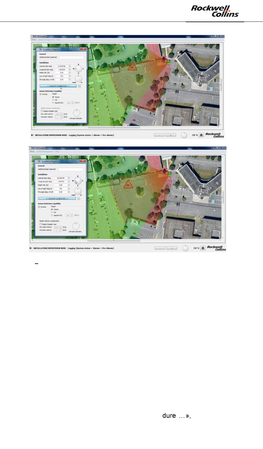
Note: when calibration mode is activated, when the installation properties are
modified, the radar information is automatically updated in real time on the display of
the application as shown in the example below:
PSR-500 System Installation Guide
Page 89 / 125
CPN 222-3044-657 Rev B CAGEC F5491 Rockwell Collins - Proprietary Information
Figure 125 Radar installation properties modification effect during radar calibration phase
Note: the user can observe that when he is connected to the radar, the installation
properties can only be modified when the calibration mode is activated.
Note: If the operator does not have any background map to align the radar (in the
desert for instance), the camera will only be aligned with the radar as explained
below.
6.4.2. Camera Alignement and standby position setting
6.4.2.1. Camera alignment
The objective of this step is to update the camera installation properties so that the
camera pointing fits with the alerts. Once this will be performed, since the radar is
already aligned, the associated camera will then be aligned with the alerts raised by
the radar.
The following steps shall be performed for each camera (each CCS):
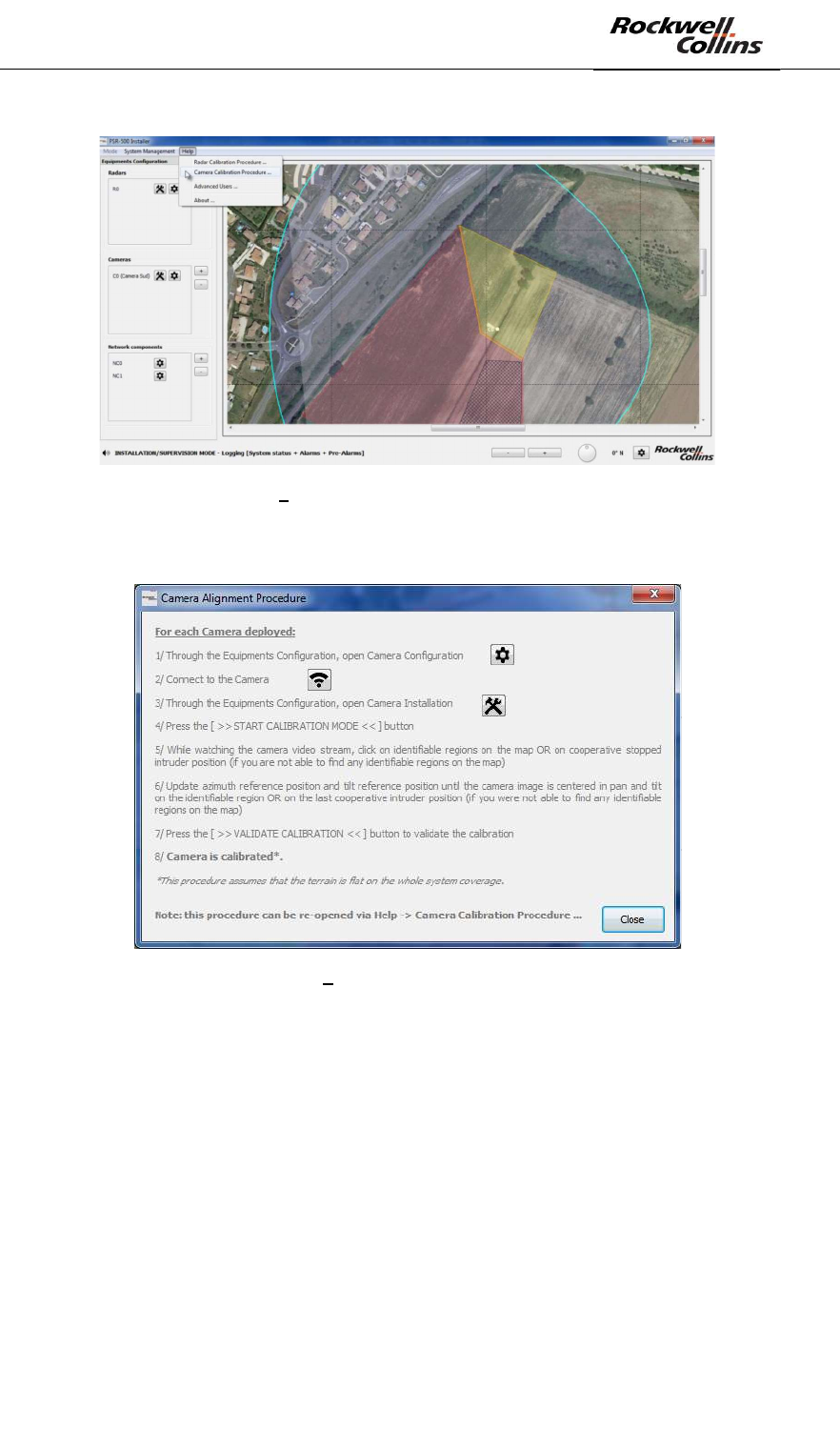
- Open the camera calibration procedure through the « Help » tab of the menu
bar, then click on « Camera Calibration Proce as illustrated by the
following figure:
PSR-500 System Installation Guide
Page 90 / 125
CPN 222-3044-657 Rev B CAGEC F5491 Rockwell Collins - Proprietary Information
Figure 126 Open the Camera calibration procedure
- The following window automatically opens
Figure 127 Camera alignment procedure
The 10 steps shall be performed to correctly calibrate the camera.
This procedure consists in ensuring that the camera knows its position of reference
and point toward the requested direction. If possible, the user will prefer remarkable
positions over the map. If remarkable position are not available (desert zone for
instance), the user will rely on a cooperative intruder that is static on the radar
coverage zone.
To connect to the camera, click on the button with the gear at the right of the camera
to align.
PSR-500 System Installation Guide
Page 91 / 125
CPN 222-3044-657 Rev B CAGEC F5491 Rockwell Collins - Proprietary Information
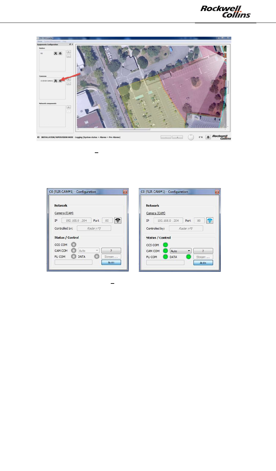
Figure 128 Open the camera connection window
The Control Camera Software module is automatically launched and the connection
window is updated as illustrated below:
Figure 129 Connection to the camera
- CCS COM = indicate the CCS module status
- CAM COM = indicate the status of the connection with the IP camera
- PU COM = Indicate the status of the connection from the CSS to the radar
(PU)
o DATA = if green, indicate that there is traffic exchanged between the
radar and the CSS.
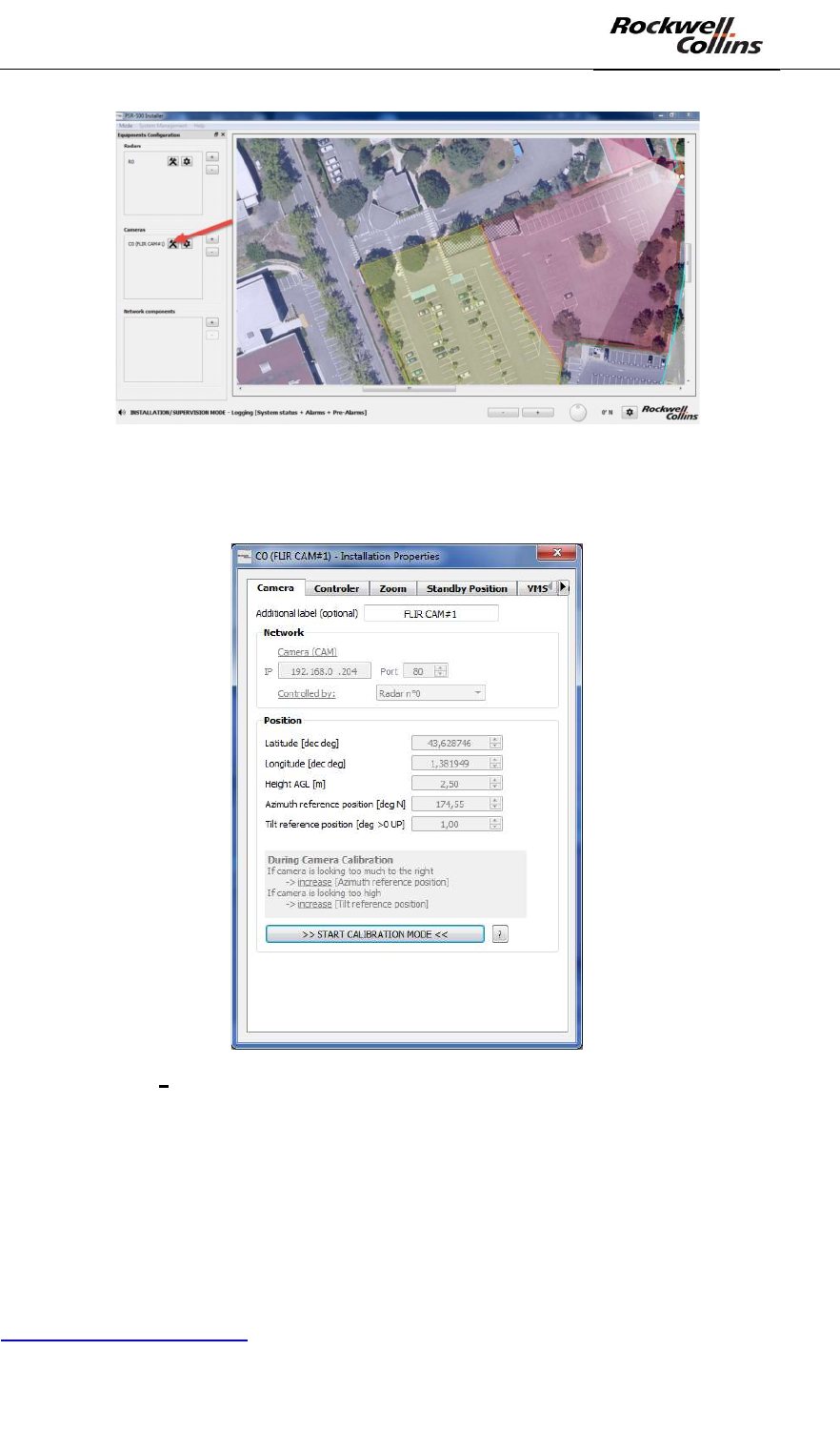
Click on the button (as shown below) to open the camera installation properties
modification window.
PSR-500 System Installation Guide
Page 92 / 125
CPN 222-3044-657 Rev B CAGEC F5491 Rockwell Collins - Proprietary Information
Figure 130 - Ouverture de la fenêtre de configuration des propriétés
The following window opens; the « << START CALIBRATION MODE >> is clickable.
Figure 131 Camera Installation properties window when a camera is connected
Note: the operator does not need to be connected to the radar to align the camera.
The two sensors are aligned based on the background map, in a totally independent
way.
As described in the procedure, to be able to align the camera, we shall display the
camera video stream. To do so, several solutions are available.
The recommended solution is to use the camera web page. Enter
http://adresse_IP_camera in a web browser.
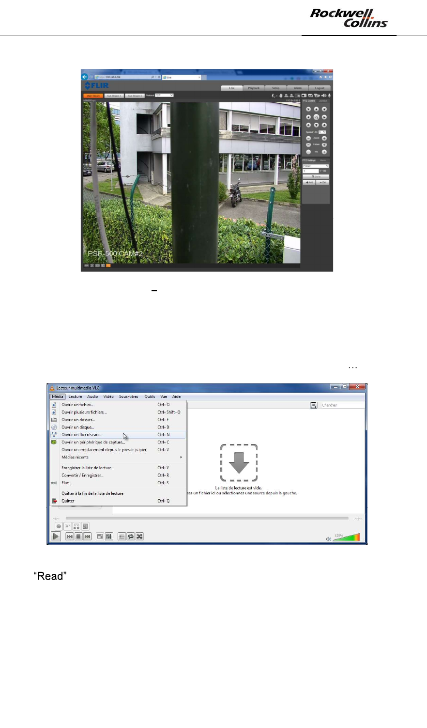
PSR-500 System Installation Guide
Page 93 / 125
CPN 222-3044-657 Rev B CAGEC F5491 Rockwell Collins - Proprietary Information
Figure 132 Example of an IP camera web page
The other solution is to use VLC application. This solution induces a more important
latency than the previous one. To use VLC::
- Start VLC application
- Through the « Media » menu, Click on « Open a network stream »
- In the « network» tab, enter the URL of the camera video stream and click on
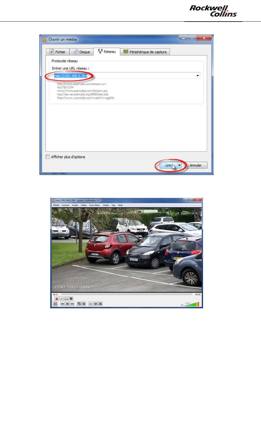
PSR-500 System Installation Guide
Page 94 / 125
CPN 222-3044-657 Rev B CAGEC F5491 Rockwell Collins - Proprietary Information
- VLS displays the camera video stream
- Click on « view » and then « Minimal Interface » or CTRL+H to keep only the
video stream on the screen
By default VLC does not remain on top. To do so and be able to maintain both the
PSR-500 Installer and the video stream on the screen, use an application such as
the DeskPins software. Start DeskPins, click on « Enter pin mode » then move the
pin to the VLC window and left click on VLC window top menu bar. VLC will now
remain on top of the screen.
PSR-500 System Installation Guide
Page 95 / 125
CPN 222-3044-657 Rev B CAGEC F5491 Rockwell Collins - Proprietary Information
Figure 133 DeskPins use
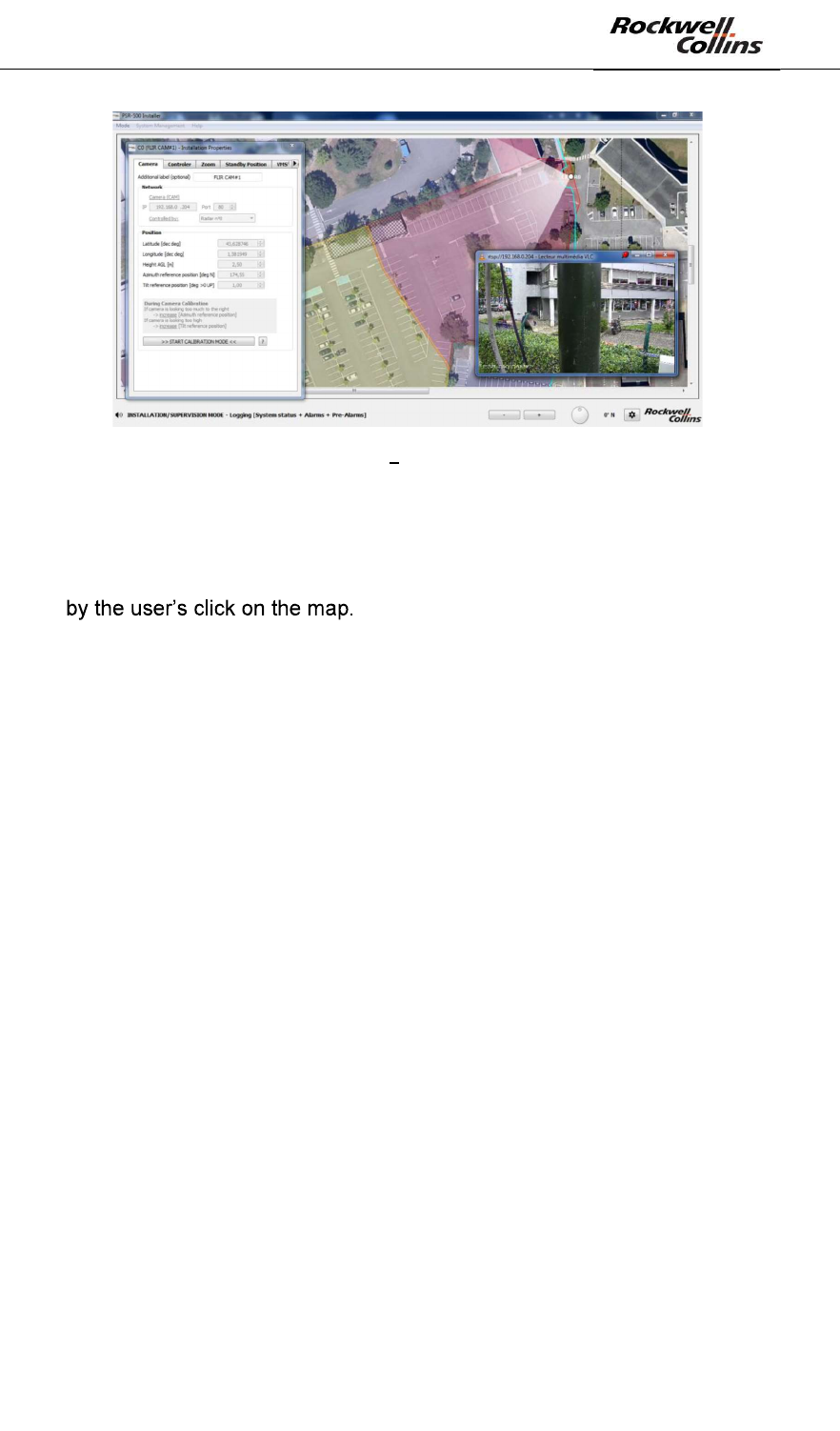
To calibrate the camera :
- In the camera installation properties window, click on >> START
CALIBRATION MODE <<. The camera is no more controlled by the radar but
- Select a point of interest on the map with the mouse. The selected point of
interest is marked on screen by the yellow cross. In the following example, the
point of interest is the angle of a building.
PSR-500 System Installation Guide
Page 96 / 125
CPN 222-3044-657 Rev B CAGEC F5491 Rockwell Collins - Proprietary Information
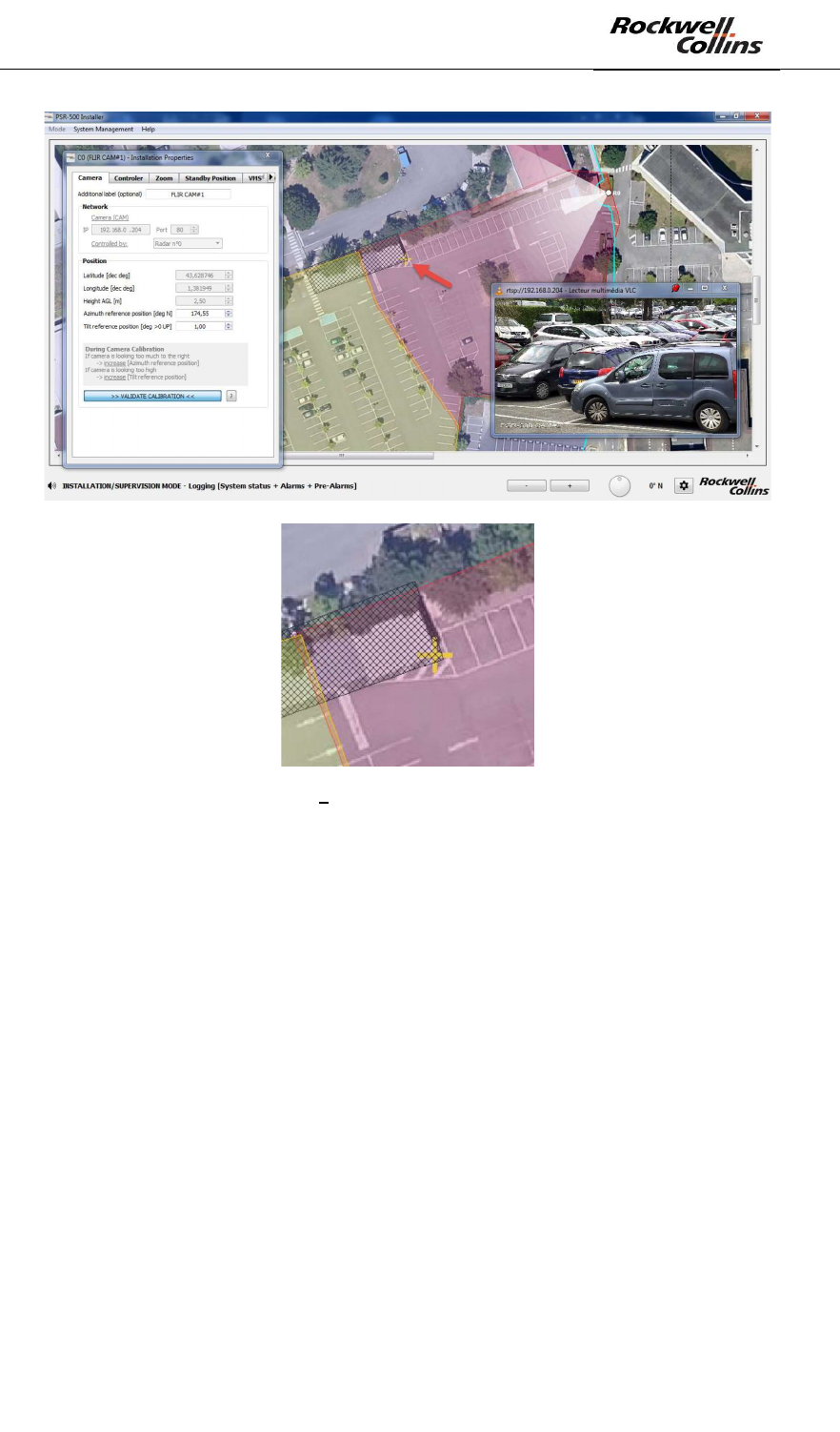
Figure 134 Selection of a point of interest
- The CCS module is using its current position of reference azimut and tilt
settings to steer the camera to the point of reference chosen by the user. By
default, the camera is not centered to the good position.
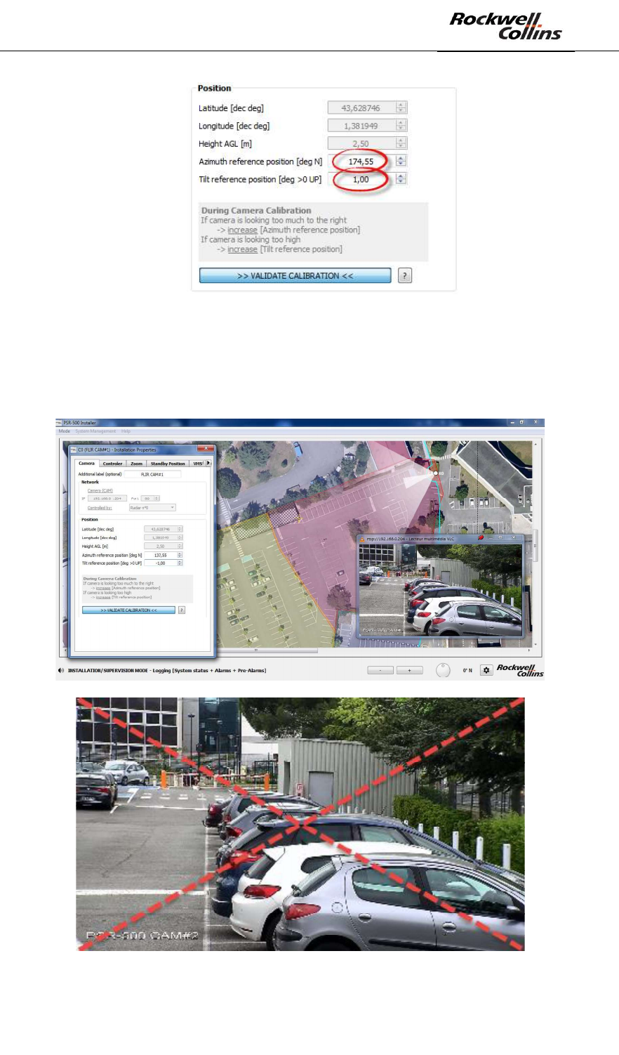
- Adjust « Azimuth reference position » and « Tilt reference position » values
until the camera image is centered on the point of reference:
o If the camera is too much on the right, increase the « Azimuth reference
position » and decrease it if too much on the left.
o If the camera is steered too high above the target, increase the « Tilt
reference position » and decrease it if the camera is steered too much
to the ground.
PSR-500 System Installation Guide
Page 97 / 125
CPN 222-3044-657 Rev B CAGEC F5491 Rockwell Collins - Proprietary Information
Figure 135: Adjust camera installation properties
- When the point of interest is centered in the camera video stream, click on >>
VALIDATE CALIBRATION << in the camera installation properties window to
validate the calibration. Our point of interest is well centered in the camera
video stream.
Figure 136: Center camera image on the point of interest
PSR-500 System Installation Guide
Page 98 / 125
CPN 222-3044-657 Rev B CAGEC F5491 Rockwell Collins - Proprietary Information
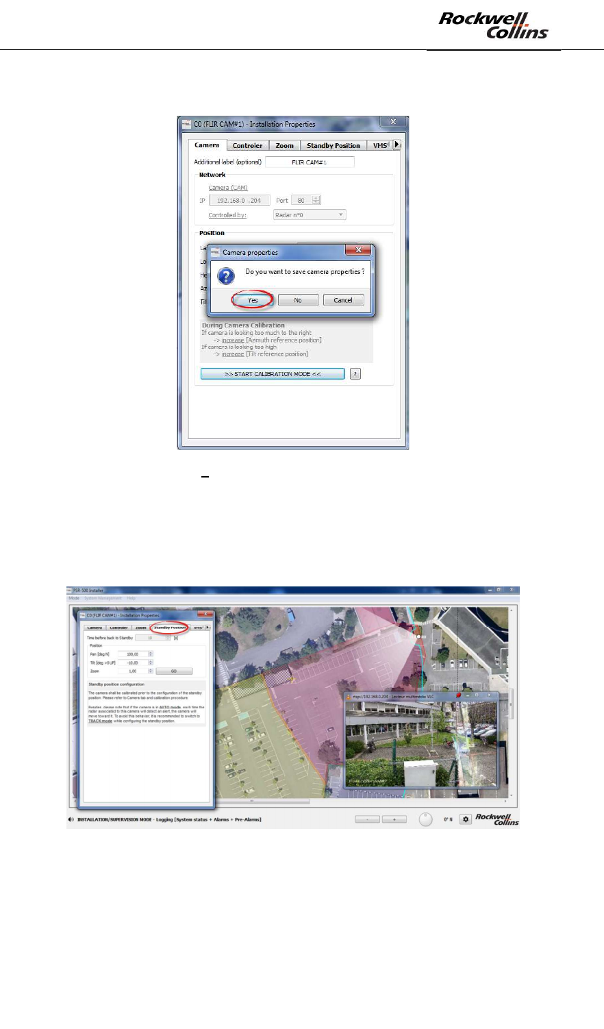
- Close the camera installation properties window and click on save.
Figure 137 Save the camera installation properties
6.4.2.2. Camera standby position setting
To set the camera standby position, open the camera installation properties window
and open the « Standby Position » tab.
Figure 138 - Camera "Standby position" tab
- As mentioned in the window, to be able to set the camera standby position, it
is essential that the camera has previously been aligned following the
procedure described above.
- By default, the CCS module is in AUTO mode. The CSS module proposes
several modes:
PSR-500 System Installation Guide
Page 99 / 125
CPN 222-3044-657 Rev B CAGEC F5491 Rockwell Collins - Proprietary Information
o AUTO = the camera will point toward each alert raised by the
associated radar one after another, based on the policy defined during
the installation in the Controller tab.
o MAP = the camera points to the position indicated by the user on the
map.
o TRACK = the camera track an alert designated by the user (by clicking
on the alert)
o PTZ = the camera point to a fixed PTZ order.
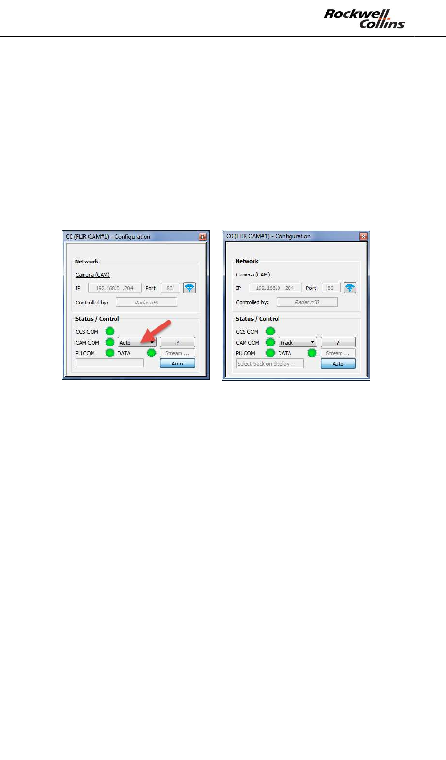
- It is recommended to set the CCS mode to TRACK during the camera standby
position setting. Open the camera connection window as explained previously,
select the TRACK mode in the dedicated drop-down menu.
Figure 139 - Selection of the TRACK mode
- In the camera installation properties window, modify the standby position
setting the pan, Tilt and zoom values. Each time a value is modified, the
camera update its real position automatically so that the user is able to see its
new position. As indicated in the window,:
o The PAN standby position is defined with respect to the geographical
North (clockwise)
o The TILT standby position is defined with respect to the horizontal
(positive value toward the top)
- Once the standby position set, the CCS mode can be set back to AUTO. The
camera will get back to this standby position automatically as soon as there is
no alert on the associated radar coverage.
Note: All the grey fields of the camera installation properties modification window are
only accessible when the application is not connected to the camera. To modify
them, use the camera connection window. If these fields are modified, it is necessary
to close the camera installation properties modification window, and same them.
These new values will be taken into account at the next connection to the camera.
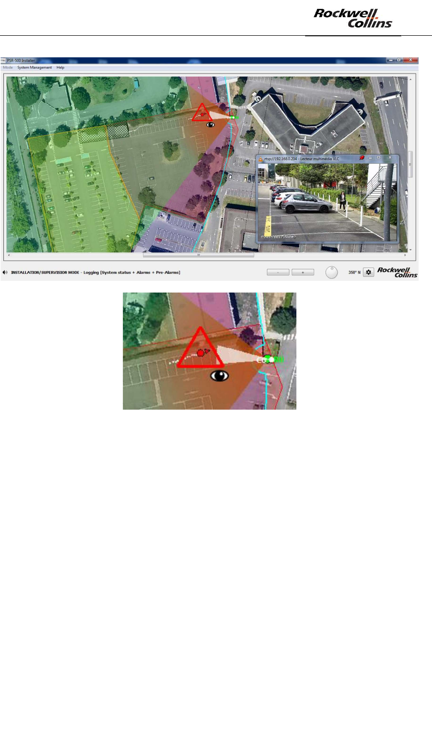
When the application is connected to the radar and to the camera(s) associated to
this radar, as soon as an alert is raised, the camera is steered toward the alert. On
the application, the alert currently tracked by the camera is identified through an
additional icon and the camera field of view representation is also turned toward the
alert.
PSR-500 System Installation Guide
Page 100 / 125
CPN 222-3044-657 Rev B CAGEC F5491 Rockwell Collins - Proprietary Information
Figure 140 - Identification of an alert tracked by a camera