Rockwell Collins 5972410 Perimeter Surveillance Radar User Manual EN 222 3044 657 Installation Guide PSR 500
Rockwell Collins Inc Perimeter Surveillance Radar EN 222 3044 657 Installation Guide PSR 500
Contents
- 1. User Manual 1-40
- 2. User Manual 41-80
- 3. User Manual 81-100
- 4. User Manual 101-125
User Manual 1-40
PSR-500 System Installation Guide
Page 1 / 125
CPN 222-3044-657 Rev B CAGEC F5491 Rockwell Collins - Proprietary Information
System Installation Guide
-
PSR-500 System
CPN 222-3044-657 Rev B
NOTICE: The contents of this document are proprietary of Rockwell Collins France
and shall not be disclosed, disseminated, copied, or used except for purposes
expressly authorized in writing by Rockwell Collins France.
Rockwell Collins France
6, avenue Didier Daurat
B.P 20008 31701 Blagnac France
CAGEC F5491

PSR-500 System Installation Guide
Page 2 / 125
CPN 222-3044-657 Rev B CAGEC F5491 Rockwell Collins - Proprietary Information
Notices
This document is a paper representation of the master copy which is maintained in RCF's Software
Control Library (SCL) database.
The following software was used to produce this document:
- Desktop Publisher: Microsoft® Office Word 2010.
Approval Signatures
Name
Date
Signature
Prepared by: J-P Wasselin
Prepared by: F. Martin
Verified by: S. Laffont
RCF Quality
Assurance: A. Jean-Jean

PSR-500 System Installation Guide
Page 3 / 125
CPN 222-3044-657 Rev B CAGEC F5491 Rockwell Collins - Proprietary Information
Revision Table
Rev
Date
By
Change description
- June 24th, 2016
J-P. Wasselin
S. Laffont Creation
A June 28th, 2017
JP. Wasselin General review + addition of troubleshooting
section
August 25th,
2017 JP. Wasselin Add major step for launching PSR-500 Server in
Service
September 6th,
2017 JP. Wasselin Add explanations for effect of traffic road on the
PSR-500 radars system performances
September
19th, 2017 F. Gayraud Add chapter for CE anf FCC marking
B December 5th,
2017 F.Martin
Add Web Services CAM_TRACKING (v1.3) &
Usage of Dry Contacts for alerting (v1.4) new
functionalities. Remove NetBooter Network
Component (no more used). Remove §7 detail
written in french.
PSR-500 System Installation Guide
Page 4 / 125
CPN 222-3044-657 Rev B CAGEC F5491 Rockwell Collins - Proprietary Information
Table of Content
1. OBJECTIVE OF THE DOCUMENT ............................................................................................... 9
2. APPLICABLE DOCUMENTS AND REFERENCES ...................................................................... 9
2.1. APPLICABLE DOCUMENTS .......................................................................................................... 9
2.2. ACRONYMS .............................................................................................................................. 9
3. NOTE FOR INSTALLATION OPERATOR .................................................................................. 10
4. PSR-500 SYSTEM PRESENTATION .......................................................................................... 11
4.1. POSSIBLE SYSTEM ARCHITECTURE ......................................................................................... 12
4.1.1. Standalone Deployment .............................................................................................. 12
4.1.2. Integrated deployment ................................................................................................. 13
4.2. SYSTEM ELEMENTS DEFINITION ............................................................................................... 15
4.2.1. Sensor Unit (SU) ......................................................................................................... 15
4.2.2. Processing Unit (PU) ................................................................................................... 15
4.2.3. PSR-500 Installer ........................................................................................................ 16
4.2.4. PSR-500 Server .......................................................................................................... 16
4.2.5. PSR-500 Viewer .......................................................................................................... 17
4.2.6. PSR-500 Investigator .................................................................................................. 17
4.2.7. CCS Module (Camera Control Software) - Optional ................................................... 17
5. GENERALS RECOMMANDATIONS ........................................................................................... 18
5.1. WARNINGS ............................................................................................................................. 18
5.2. MANUFACTURER ADDRESS ...................................................................................................... 18
5.3. REGIONAL AREA USE .............................................................................................................. 18
5.4. DECLARATION OF CONFORMITY ............................................................................................... 19
6. SYSTEM INSTALLATION ............................................................................................................ 19
6.1. DEPLOYMENT PREPARATION ................................................................................................... 19
6.1.1. Step#1 : Import and reference a background map of the site ..................................... 20
6.1.1.1. Background map import ....................................................................................................... 20
6.1.1.2. Define map references in PSR-500 Installer application ...................................................... 24
6.1.2. Step#2 : Define site surveillance ................................................................................. 33
6.1.3. Step#3: Add, position and configure one or several radars (SU+PU) ........................ 39
6.1.3.1. .................................................................... 39
6.1.3.2. Position the radar effectively ................................................................................................ 42
6.1.4. Step#4: Add, position and configure one or several cameras (CCS) ......................... 53
6.1.5. Step#5: add and configure network components ........................................................ 57
6.1.5.1. Configuration of Maintenance through POE switch and Dry Contact ................................... 59
6.1.5.2. Dry Contact trigerring on zone in alarm ................................................................................ 62
6.1.6. Step#6: Generate the preliminary installation report ................................................... 63
6.1.7. Step#7: Visit the site and Validate/Update the foreseen installation ........................... 65
6.1.8. Step#8: Add installation operators .............................................................................. 69
6.2. INSTALLATION & START OF A RADAR ......................................................................................... 71
6.2.1. Cabling ........................................................................................................................ 71
6.2.2. Dimensions .................................................................................................................. 71
6.2.3. Power Supply .............................................................................................................. 72
6.2.4. Energy Consumption ................................................................................................... 72
6.2.5. Direction of installation ................................................................................................ 72
6.2.6. Network configuration .................................................................................................. 74
6.2.7. SU to PU connection ................................................................................................... 75
6.2.8. Radar Power Up .......................................................................................................... 75
6.2.9. Update of each PU ...................................................................................................... 75
6.3. INTEROPERABILITY OF THE RADARS ......................................................................................... 77
6.3.1. Relative positioning ..................................................................................................... 78
6.3.2. Radio environment analysis ........................................................................................ 80
6.3.3. Radar interoperability setting ....................................................................................... 83
6.3.3.1. General principle .................................................................................................................. 83

PSR-500 System Installation Guide
Page 5 / 125
CPN 222-3044-657 Rev B CAGEC F5491 Rockwell Collins - Proprietary Information
6.4. ALIGNMENT ............................................................................................................................ 84
6.4.1. Alignment of a radar .................................................................................................... 84
6.4.2. Camera Alignement and standby position setting ....................................................... 89
6.4.2.1. Camera alignment ................................................................................................................ 89
6.4.2.2. Camera standby position setting .......................................................................................... 98
6.5. VALIDATION .......................................................................................................................... 101
6.5.1. Equipment and installation properties update ........................................................... 101
6.5.2. Zone update .............................................................................................................. 103
6.5.3. End of the validation phase ....................................................................................... 104
7. 24H OPERATION OF THE RADAR SYSTEM ........................................................................... 105
8. SYSTEM PERFORMANCES OPTIMIZATION .......................................................................... 106
8.1. DETECTION CAPABILITY ......................................................................................................... 106
8.1.1. Reactivity ................................................................................................................... 106
8.1.2. Localization accuracy ................................................................................................ 106
8.1.3. Effect of the outside temperature .............................................................................. 107
8.2. FALSE ALARM ....................................................................................................................... 107
8.3. OBSERVATION PERIOD ACTIVATION ........................................................................................ 108
8.4. INVESTIGATION ..................................................................................................................... 109
8.4.1. Register loading ......................................................................................................... 111
8.4.2. Replay of a single alarm ............................................................................................ 112
8.4.3. Accumulation of observed activity on one day .......................................................... 114
8.5. FALSE ALARM MITIGATION ..................................................................................................... 116
8.6. MITIGATION VALIDATION ........................................................................................................ 116
9. MAINTENANCE & TROUBLESHOOTING ................................................................................ 117
9.1. DISPLAY OF THE RADAR COVERING AREA ............................................................................... 117
9.2. CONTROL THE STATUS OF THE DEPLOYED RADARS ................................................................. 117
9.3. CONTROL THE CCS MODULES STATUS .................................................................................. 121
9.4. CONTROL THE STATUS OF THE DATA FLOW THAT CAMES OUT OF THE PSR-500 SERVER .......... 123
9.5. CONTROL THE RADAR AND/OR CAMERA ALIGNMENT STATUS .................................................... 123
10. ANNEXES .............................................................................................................................. 124
10.1. QUICK INSTALLATION GUIDE FOR THE PSR-500 .................................................................... 124
PSR-500 System Installation Guide
Page 6 / 125
CPN 222-3044-657 Rev B CAGEC F5491 Rockwell Collins - Proprietary Information
List of Figures
Figure 1: Aperçu du système PSR-500 ................................................................................................. 11
Figure 2: PSR-500 system radar detection area for human intrusion detection ................................... 11
Figure 3 Standalone System architecture of PSR-500 system (2 radars configuration) ................... 12
Figure 4: Standalone System architecture of PSR-500 system with CCS option ................................. 13
Figure 5: Integrated System architecture for PSR-500 System (two radars configuration) .................. 14
Figure 6: Integrated System architecture of PSR-500 System with CCS option .................................. 15
Figure 7: Locate the zone with Google Earth ........................................................................................ 20
Figure 8: Google Earth scale factor ....................................................................................................... 21
Figure 9: Close Option menus of Google Earth .................................................................................... 21
Figure 10: Google Earth map Nord oriented ......................................................................................... 22
Figure 11: Save picture on Google Earth .............................................................................................. 22
Figure 12: Unselect display options of Google Earth ............................................................................ 23
Figure 13: Selection of the picture resolution on Google Earth............................................................. 23
Figure 14: Save the map ....................................................................................................................... 24
Figure 15 PSR-500 Installer Authentification window ..................................................................... 24
Figure 16: PSR-500 Installer Creation of a new system configuration .............................................. 25
Figure 17: PSR-500 Installer New System configuration name ......................................................... 25
Figure 18: PSR-500 Installer Select Google Earth map ..................................................................... 25
Figure 19: PSR-500 Installer Confirm that the map is north-oriented ................................................ 26
Figure 20: PSR-500 Installer Select the mode to define map references .......................................... 26
Figure 21: PSR-500 Installer Identification of point [Reference 1] on PSR map................................ 27
Figure 22: PSR-500 Installer Validation du point [Reference 1] sur la carte ...................................... 27
Figure 23: PSR-500 Installer Enter GPS latitude / longitude of point [Reference 1] .......................... 28
Figure 24: PSR-500 Installer Localize point [Reference 1] on Google Earth ..................................... 28
Figure 25: PSR-500 Installer Get GPS coordinate with « pin » tool on Google Earth ....................... 29
Figure 26: PSR-500 Installer Validation of GPS coordinates of point [Reference 1] on the map ...... 29
Figure 27: PSR-500 Installer Identify point [Reference 2] on the PSR map ..................................... 30
Figure 28: PSR-500 Installer Validation of point [Reference 2] on PSR map .................................... 30
Figure 29: PSR-500 Installer Save coordinates of point [Reference 2] ............................................. 31
Figure 30: PSR-500 Installer localize the point [Reference 2] on Google Earth ................................ 31
Figure 31: PSR-500 Installer Get GPS coordinate with « pin » tool on Google Earth ....................... 32
Figure 32: PSR-500 Installer Validation of GPS coordinates of point [Reference 2] on the map ...... 32
Figure 33: PSR-500 Installer Map references correctly set up .......................................................... 33
Figure 34: Zone definition Create zones ............................................................................................ 34
Figure 35: Zone Creation Instructions to follow to create a zone ....................................................... 34
Figure 36: PSR-500 Installer Creation of a first zone of surveillance ................................................ 35
Figure 37: PSR-500 Installer Add a point in an already defined zone ............................................... 35
Figure 38: PSR-500 Installer Exit of the zone creation mode ............................................................ 36
Figure 39: PSR-500 Installer Configuration of the properties of the surveillance zone. .................... 36
Figure 40: PSR-500 Installer Configuration parameters of a surveillance zone ................................ 37
Figure 41: PSR-500 Installer Addition of a caution zone and an exclusion zone .............................. 38
Figure 42: PSR-500 Installer End of the zone creation ...................................................................... 38
Figure 43: PSR-500 Installer « Information » window at the end of step#2 ....................................... 39
Figure 44: PSR-500 Installer Add a radar .......................................................................................... 39
Figure 45: RCS evolution depending on the target type ....................................................................... 40
Figure 46: Detection zone for a human intrusion (left) and for a car (right) .......................................... 41
Figure 47: Illustration radial velocity (3D/2D) ........................................................................................ 41
Figure 48: transverse trajectory case (3D/2D) ...................................................................................... 42
Figure 49: PSR-500 Installer Positioning of a radar on the map ........................................................ 43
Figure 50: Example on an intrusion scenario on a site ......................................................................... 43
Figure 51: Not recommended radar installation .................................................................................... 44
Figure 52: PSR-500 Installer Display the Doppler Rose .................................................................... 44
Figure 53: PSR-500 Installer - Doppler Rose displayed ....................................................................... 45
Figure 54: PSR-500 Installer Setting of the Doppler Rose ................................................................. 45
Figure 55: PSR-500 Installer Doppler Rose aligned with expected intrusions ................................... 46
Figure 56: PSR-500 Installer Possible Installation #1 ........................................................................ 47
PSR-500 System Installation Guide
Page 7 / 125
CPN 222-3044-657 Rev B CAGEC F5491 Rockwell Collins - Proprietary Information
Figure 57: PSR-500 Installer - Possible Installation #2 ......................................................................... 47
Figure 58: PSR-500 Installer - Possible Installation #3 ......................................................................... 48
Figure 59: PSR-500 Installer sensibility increase and possible Installation #4 .................................. 48
Figure 60: Position/height of the radar w.r.t the shadow zone .............................................................. 49
Figure 61: Radar height modification .................................................................................................... 49
Figure 62: Impact of radar position/height on detection capability ........................................................ 50
Figure 63: Modification of the tilt angle to improve detection capability ................................................ 50
Figure 64: Closing the « Installation Properties » window .................................................................... 51
Figure 65: Opening radar configuration window ................................................................................... 51
Figure 66 : Dockable configuration window........................................................................................... 52
Figure 67: Configuration réseau SU & PU ............................................................................................ 52
Figure 68: Add a camera ....................................................................................................................... 53
Figure 69: Set the position and the orientation of the camera .............................................................. 54
Figure 70 Camera properties configuration window » tab ............................................... 54
Figure 71 Camera properties configuration window « Controller » tab .......................................... 55
Figure 72 - Camera properties configuration window « Zoom » tab ................................................... 56
Figure 73 - Camera properties configuration window « Standby position » tab................................. 56
Figure 74: Close the camera « Installation Properties » window ......................................................... 57
Figure 75 - Examples of compatible POE switch .................................................................................. 57
Figure 76 - Module audio E/S AXIS P8221 ........................................................................................... 58
Figure 77: Add a network component ................................................................................................... 58
Figure 78: Select Network Component window .................................................................................... 59
Figure 79: « configuration » button associated to the network component ........................................... 59
Figure 80: POE Switch configuration window ....................................................................................... 59
Figure 81: Selection of the POE switch for the automatic maintenance of the SU ............................... 60
Figure 82: Dry Contact Configuration window ....................................................................................... 61
Figure 83: Select the Dry Contact for the automatic maintenance of the PU ....................................... 61
Figure 84: Radar monitored and under automatic maintenance ........................................................... 62
Figure 85: Dry Contact in « Single Pulse » mode configuration window .............................................. 62
Figure 86: Dry Contact Selection for zone alerting ............................................................................... 63
Figure 87: Button to generate the preliminary installation report .......................................................... 64
Figure 88: Preliminary Installation report is correctly generated ........................................................... 64
Figure 89: Preliminary installation report ............................................................................................... 64
Figure 90: End of installation window .................................................................................................... 65
Figure 91: Close the PSR-500 Installer and save the system configuration ......................................... 65
Figure 92 PSR-500 Installer Authentification window ..................................................................... 67
Figure 93: PSR-500 Installer « » button ............................................................................. 68
Figure 94: PSR-500 Installer « Add / Configure Equipments » button ................................................ 68
Figure 95: PSR-500 Installer open the saved system configuration .................................................. 69
Figure 96: PSR-500 Installer Generate installation report from the menu bar ................................... 69
Figure 97: PSR-500 Installer Add installation operators .................................................................... 70
Figure 98: PSR-500 Installer installation operator creation window .................................................. 70
Figure 99: PSR-500 SU plug ................................................................................................................. 71
Figure 100: Ethernet Connector RJF RB 6 ........................................................................................... 71
Figure 101: Position of the GPS antenna on the PSR-500 radar ......................................................... 72
Figure 102: Radar of the PSR-500 correctly oriented ........................................................................... 73
Figure 103: Arrow/text on the edge of the radar ................................................................................... 73
Figure 104: line of sight of the PSR-500 radar ...................................................................................... 74
Figure 105: Tilt indications for the PSR-500 radar ................................................................................ 74
Figure 106: Connection to the PU of a radar ......................................................................................... 75
Figure 107: System configuration alignment window ............................................................................ 76
Figure 108: Synchronization of the emissions of the SU thanks to the GPS signal.............................. 77
Figure 109: GPS antenna position on the PSR-500 radar .................................................................... 78
Figure 110: Example of jamming of the SU1 by the SU2 due to the buildings ..................................... 78
Figure 111: Abacuses of minimum physical isolation ........................................................................... 80
Figure 112: setting of a radar delay ....................................................................................................... 80
Figure 113: Connection to the PU of a radar ......................................................................................... 81
Figure 114: Configuration alignment window ........................................................................................ 81
Figure 115: PSR-500 Installer Activate observation period ............................................................... 82
Figure 116 - "interference" gauge ......................................................................................................... 82
PSR-500 System Installation Guide
Page 8 / 125
CPN 222-3044-657 Rev B CAGEC F5491 Rockwell Collins - Proprietary Information
Figure 117: PSR-500 Installer ............................. 84
Figure 118 PSR-500 Installer Authentification window ................................................................... 84
Figure 119: PSR-500 Installer « » button .......................................................................... 85
Figure 120: PSR-500 Installer « Radar(s) alignment procedure » ...................................................... 85
Figure 121: PSR-500 Installer Alignment procedure window ............................................................. 86
............................................................................................ 86
Figure 123: Radar calibration procedure through the Help menu ......................................................... 87
Figure 124 Handling during radar alignment ...................................................................................... 88
Figure 125 Radar installation properties modification effect during radar calibration phase ............. 89
Figure 126 Open the Camera calibration procedure .......................................................................... 90
Figure 127 Camera alignment procedure........................................................................................... 90
Figure 128 Open the camera connection window .............................................................................. 91
Figure 129 Connection to the camera ................................................................................................ 91
Figure 130 - Ouverture de la fenêtre de configuration des propriétés .................................................. 92
Figure 131 Camera Installation properties window when a camera is connected ............................. 92
Figure 132 Example of an IP camera web page ................................................................................ 93
Figure 133 DeskPins use ................................................................................................................... 95
Figure 134 Selection of a point of interest .......................................................................................... 96
Figure 135: Adjust camera installation properties ................................................................................. 97
Figure 136: Center camera image on the point of interest .................................................................... 97
Figure 137 Save the camera installation properties ........................................................................... 98
Figure 138 - Camera "Standby position" tab ......................................................................................... 98
Figure 139 - Selection of the TRACK mode .......................................................................................... 99
Figure 140 - Identification of an alert tracked by a camera ................................................................. 100
Figure 141 Equipment installation properties update ....................................................................... 101
Figure 142 - PSR-500 Installer - Extension of the radar configuration window .................................. 102
Figure 143 Zones update ................................................................................................................. 103
Figure 144:update of the system configuration of all the radars ......................................................... 103
Figure 145 Manual generation of the installation report ................................................................... 104
Figure 146: PSR-500 Server Observation period activation ............................................................ 108
Figure 147 Memory register analysis ............................................................................................... 109
Figure 148 System configuration folder transfer .............................................................................. 110
Figure 149 Activity files retrieval ....................................................................................................... 110
Figure 150 Regsiter analysis window ............................................................................................... 111
Figure 151 Observation file selection ............................................................................................... 111
Figure 152 Observation file loading .................................................................................................. 112
Figure 153 Window of alerts to retrieve ............................................................................................ 112
Figure 154 Display of alerts file ........................................................................................................ 112
Figure 155 Replay of an alarm ......................................................................................................... 113
Figure 156 Command buttons of an alarm trajectory ........................................................................ 113
Figure 157 Display of « Activity Map » ............................................................................................. 114
Figure 158 Display threshold tuning ................................................................................................. 115
Figure 159 « Activity Map » display (threshold with 10 observations) ............................................. 115
Figure 160 - « Activity Map » display (threshold with 2 observations) ................................................ 116
Figure 161 Nominal shape of the PSR-500 radar covering area ..................................................... 117
Figure 162 Opening the window to check the status of all deployed equipments ........................... 118
Figure 163 Extract related to the radar status .................................................................................. 118
Figure 164 Radar network properties configuration window ............................................................ 119
Figure 165 Evolution of the radar statuses after re-initialization ...................................................... 121
Figure 166 Window showing the status of all teh deployed equipments ......................................... 121
PSR-500 System Installation Guide
Page 9 / 125
CPN 222-3044-657 Rev B CAGEC F5491 Rockwell Collins - Proprietary Information
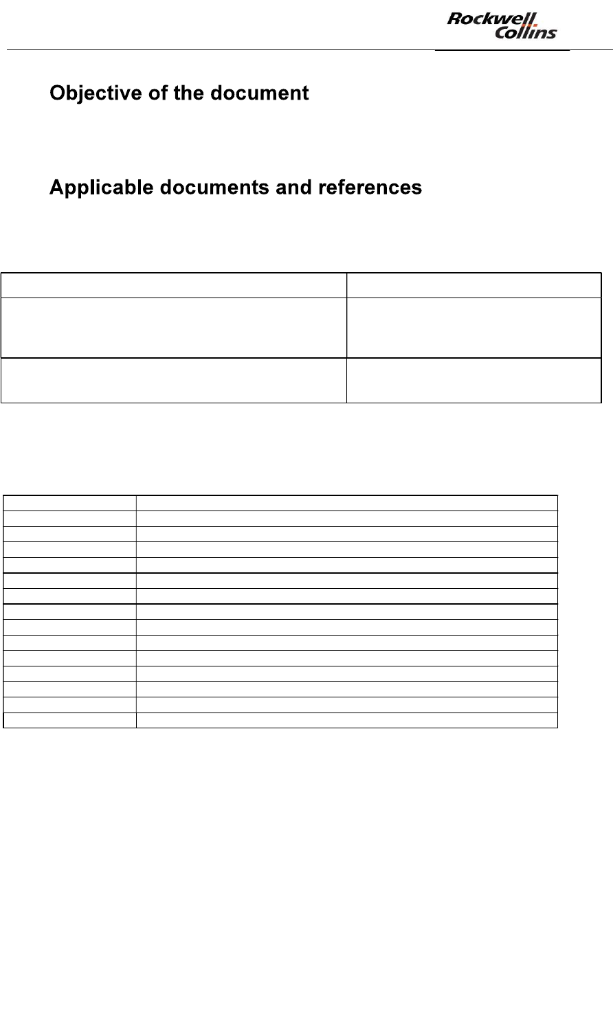
1.
This document aims at describing the full set of steps to perform to install and
configure the PSR-500 system.
2.
2.1. Applicable documents
Document Name Description
226-0098-036_Installation_Logiciels_Activation
Installation procedure of PSR-500
Systems Software:
- Tracking
- PSR-500 Installer
226-0102-036_Installation_Logiciel_PSR_IHM_Serveur
Installation procedure of PSR-500
Server :
- PSR-500 Server
2.2. Acronyms
The following abbreviations and acronyms occur in this document:
CCS Camera Control Software
COTS Commercial On The Shelf
FMCW Frequency Modulated Continuous Wave
PSR Perimeter Surveillance Radar
GPS Global Positioning System
IP Internet Protocol
ONVIF Standard Cameras Communication Protocol
PC Personal Computer
PU Processing Unit (for SU data)
PTZ Pan Tilt Zoom
RCF Rockwell Collins France
RPS Remote Power Switch
SU Sensor Unit (radar unit)
UDP User Datagram Protocol
VMS Video Management System

PSR-500 System Installation Guide
Page 10 / 125
CPN 222-3044-657 Rev B CAGEC F5491 Rockwell Collins - Proprietary Information
3.
PSR-500 System deployment requires concepts and actions that shall be mastered
in order to optimize the installation and the operational performances of the system.
Therefore, it is recommended to a new installation operator to follow this document
in its integrality for the very first deployment.
A seasoned installation operator Quick
PSR-500 System Installation guide of this document.
PSR-500 System Installation Guide
Page 11 / 125
CPN 222-3044-657 Rev B CAGEC F5491 Rockwell Collins - Proprietary Information
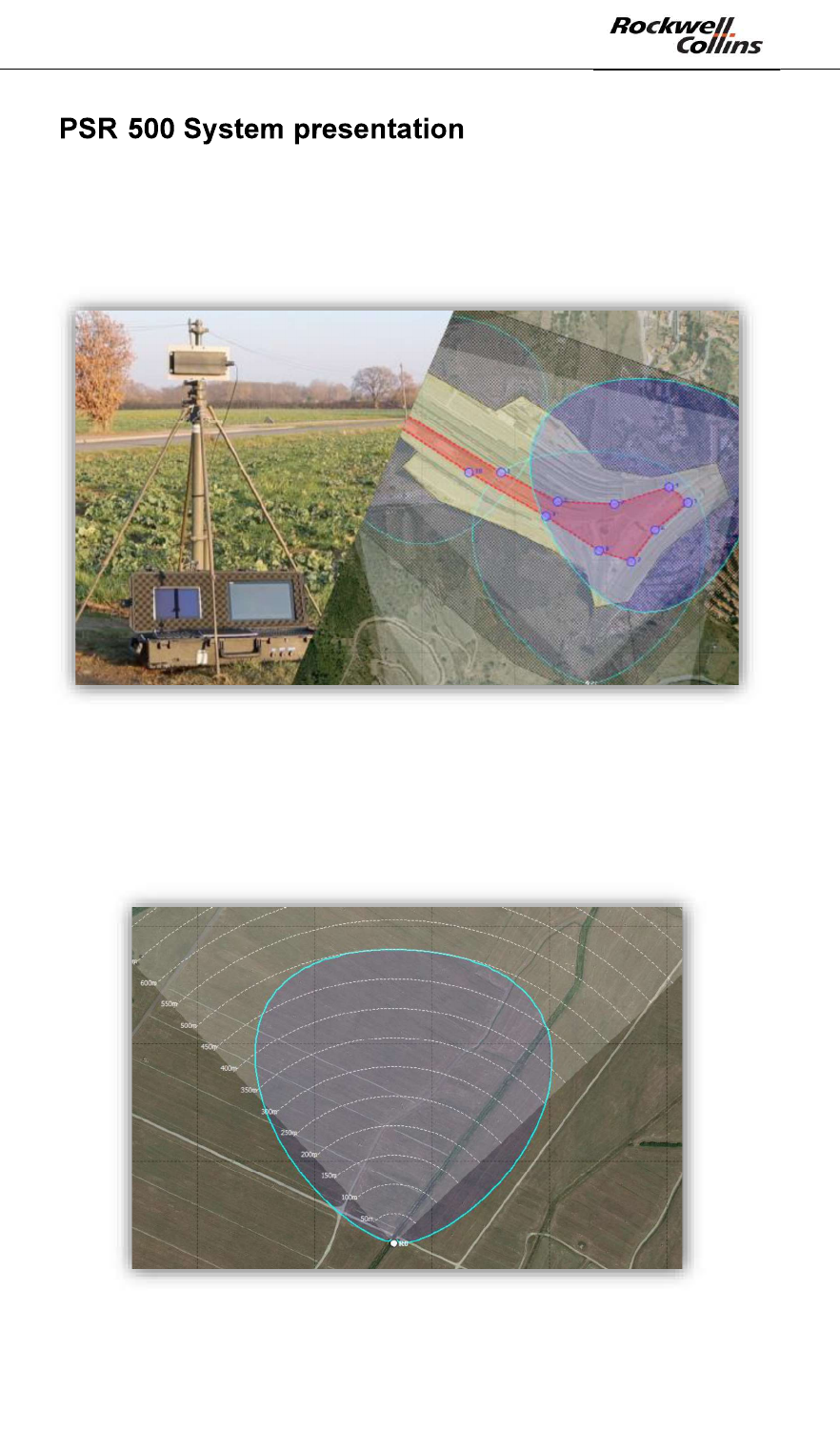
4. -
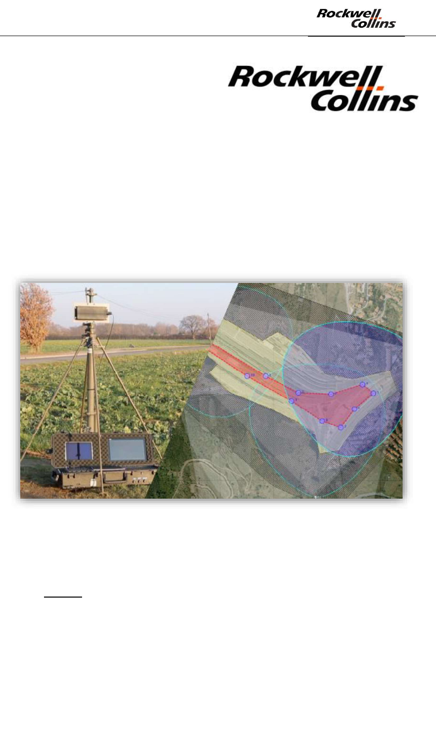
PSR-500 System is a radar system designed for surveillance and protection of critical
site against all human intrusion. In option, the PSR-500 System can be coupled with
a video camera to efficiently confirm visually the intrusion and identify the intruder
while the deployed radars monitor the whole coverage zone.
Figure 1: Aperçu du système PSR-500
In nominal operational conditions, each radar of the PSR-500 system is able to
detect any human intrusion in a zone of 90° azimuth and 500m maximum range.
The figure below show a view of the detection area (Blue area) of a PSR-500 System
radar for the detection of a human intrusion.
Figure 2: PSR-500 system radar detection area for human intrusion detection
PSR-500 System Installation Guide
Page 12 / 125
CPN 222-3044-657 Rev B CAGEC F5491 Rockwell Collins - Proprietary Information
4.1. Possible System Architecture
The architecture of the PSR-500 System may substantially differ depending on the
operational context and on possible equipment. Two general solutions of installation
are possible:
- Solution 1 = Independent standalone deployment
- Solution 2 = Integration with an external hypervisor/supervisor
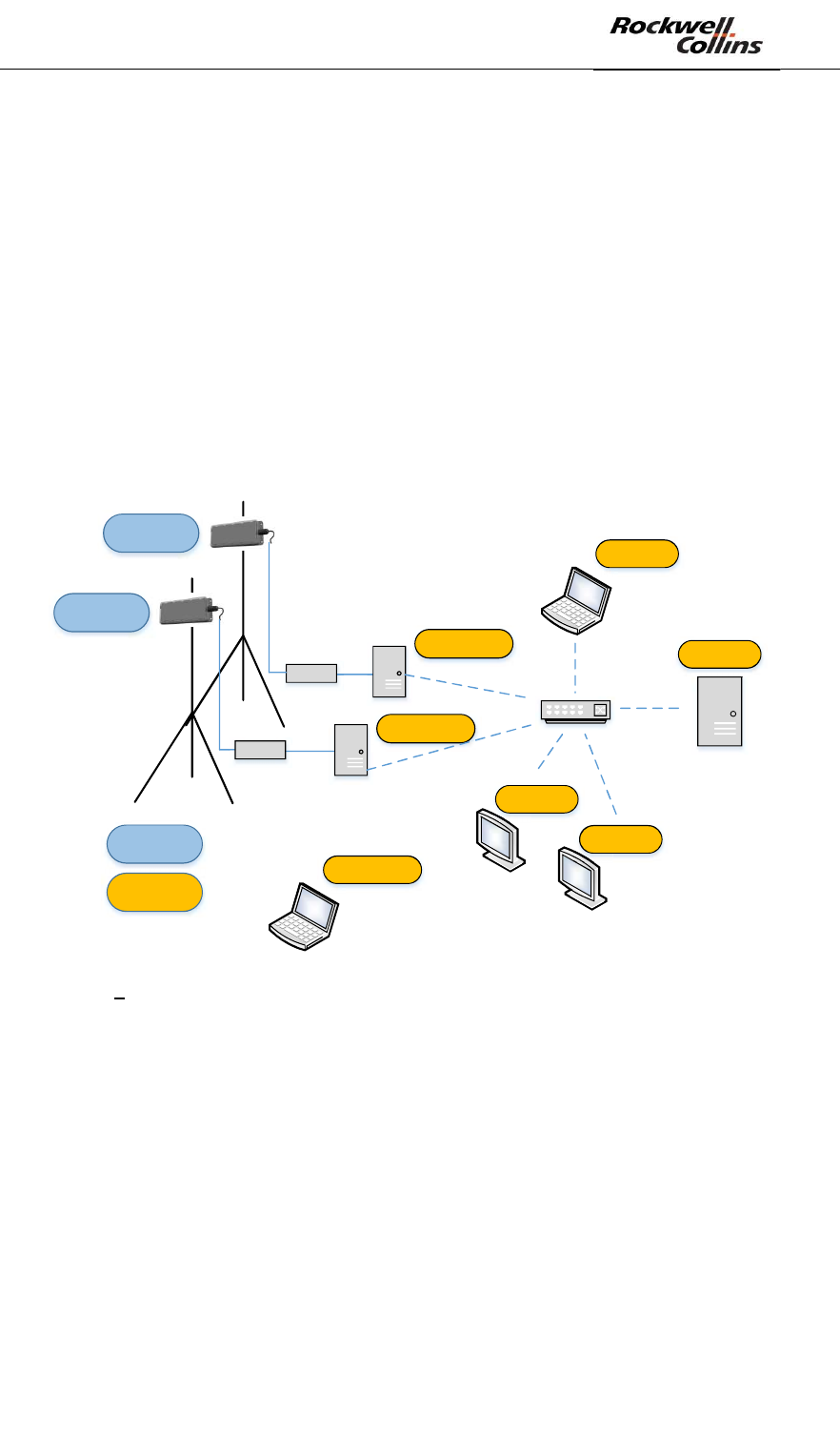
4.1.1. Standalone Deployment
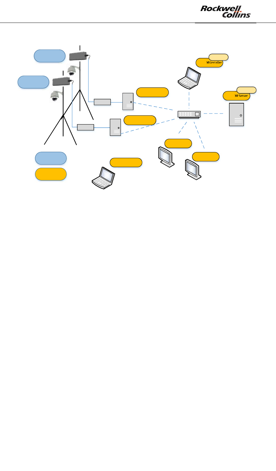
The following scheme presents a system architecture example for a standalone
deployment (solution 1) and for a 2 radars configuration. Yellow labels indicate
PSR-500 system software products that are deployed over COTS products. Blue
labels indicate PSR-500 hardware product.
POE
PU
PU
PSR-500 SU
PSR-500 SU
Hardware
Software
PSR-500 Server
PSR-500 Installer
PSR-500 Processing
PSR-500 Processing
PSR-500 Viewer
PSR-500 Viewer
POE
PSR-500 Investigator
Figure 3 Standalone System architecture of PSR-500 system (2 radars configuration)
The following components can complete the above architecture:
- Network components to perform automatic maintenance of the radars SU and
PU
- CCS software to control PTZ camera (see below)
PSR-500 System Installation Guide
Page 13 / 125
CPN 222-3044-657 Rev B CAGEC F5491 Rockwell Collins - Proprietary Information
POE
PU
PU
PSR-500 SU
PSR-500 SU
Hardware
Software
PSR-500 Server
PSR-500 Installer
PSR-500 Processing
PSR-500 Processing
POE
Option CCS
Option CCS
PSR-500 Viewer
PSR-500 Viewer
PSR-500 Investigator
Figure 4: Standalone System architecture of PSR-500 system with CCS option
Note: Cameras may or may not be co-located with radars.
4.1.2. Integrated deployment
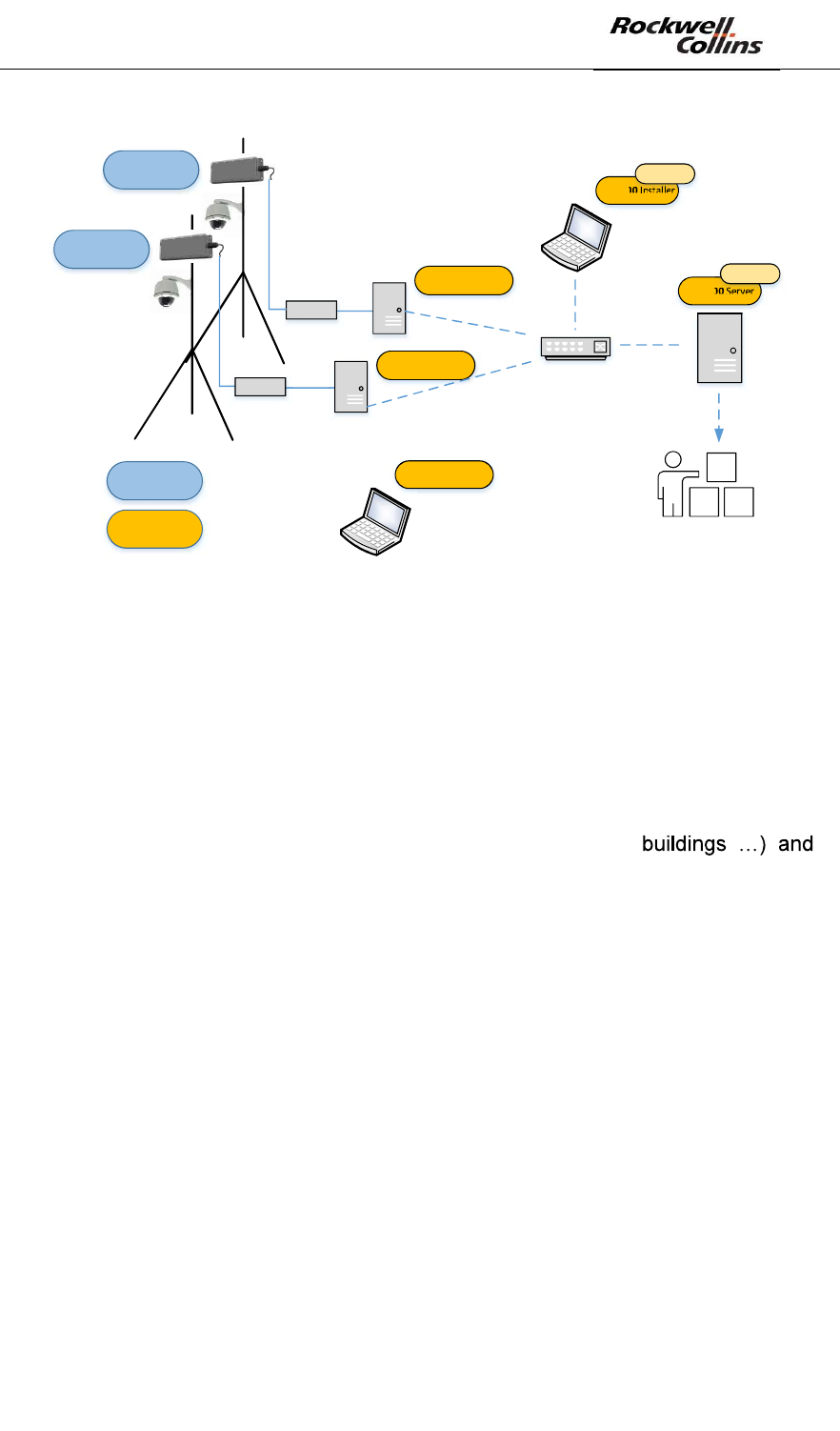
The scheme below presents a system architecture example for an integrated
deployment (solution 2) in a two radars configuration. Yellow labels indicate PSR-
500 system software products that are deployed over COTS products. Blue labels
indicate PSR-500 hardware product.

PSR-500 System Installation Guide
Page 14 / 125
CPN 222-3044-657 Rev B CAGEC F5491 Rockwell Collins - Proprietary Information
POE
PU
PU
PSR-500 SU
PSR-500 SU
Hardware
Software
PSR-500 Server
PSR-500 Installer
PSR-500 Processing
PSR-500 Processing
POE
Hyperviseur
PSR-500 Investigator
Figure 5: Integrated System architecture for PSR-500 System (two radars configuration)
Similarly to the standalone solution, additional components can complete the above
architecture:
- Network components to perform automatic maintenance of the radars SU and
PU
- CCS software to control PTZ camera (see below)
PSR-500 System Installation Guide
Page 15 / 125
CPN 222-3044-657 Rev B CAGEC F5491 Rockwell Collins - Proprietary Information
POE
PU
PU
PSR-500 SU
PSR-500 SU
Hardware
Software
PSR-500 Server
PSR-500 Installer
PSR-500 Processing
PSR-500 Processing
POE
Option CCS
Option CCS
Hyperviseur
PSR-500 Investigator
Figure 6: Integrated System architecture of PSR-500 System with CCS option
4.2. System elements definition
4.2.1. Sensor Unit (SU)
The Sensor unit is the radar. It is the active part of the system that illuminates the
area with an FMCW waveform (Frequency Modulated Continuous Wave).
The Sensor Unit transmits the signal that is backscattered by the environment
(human intrusion but also environment i.e. ground, vegetation,
received by the antenna. The received signal is digitalized within the Sensor unit and
delivered through Ethernet.
Note: Radar theory related to this technology will be reminded in the chapter
dedicated to site radar implantation choice.
4.2.2. Processing Unit (PU)
The PU is the radar processing unit. The PSR-500 Processing software is the
application running on each PU. This application aims at controlling each SU and
extracts all useful information (human intrusion vs. environment) from the radar
signal coming from the SU associated to the PU.
This software can be deployed on any PC with the following minimal characteristics:
o Processor double core Intel Core i7, cadenced at 1.3 GHz / 2.6 GHz
Turbo - 3 MB Cache
- Gigabit Ethernet
- 4Go RAM
PSR-500 Processing SW is also in charge of :
PSR-500 System Installation Guide
Page 16 / 125
CPN 222-3044-657 Rev B CAGEC F5491 Rockwell Collins - Proprietary Information
- cross-
the PSR-500 Installer SW
- broadcasting this information towards its clients.
Within the PSR-500 System, the three following software are clients listening to each
PU:
- PSR-500 Installer SW only during the installation phase.
- PSR-500 Server SW
- CCS SW module in charge of steering PTZ camera that may be deployed over
the site to protect
4.2.3. PSR-500 Installer
PSR-500 Installer SW is the application that supports and optimizes the entire
installation phase of a new PSR-500 radars park on site. This application enables to:
- Reference a background map of the operating zone
- Define alerting (with different alerting levels) and exclusion zones (detections in this
area are ignored public ways for instance) common to all radars of the site.
- update System configuration of PU deployed on site
- display stats and alerts sent by each deployed radar in order to verify and validate
their performances.
- Generate installation reports to support physical on site deployment
-
maintain the SU/PU Park deployed thanks to the PSR-500 server SW.
PSR-500 Installer shall support the PSR-500 system deployment but shall not be
used in operation phase.
4.2.4. PSR-500 Server
The PSR-500 Server SW is a basic system component that shall be deployed in any
PSR-500 System.
The PSR-500 Server SW retrieve a System configuration prepared through the PSR-
500 Installer and then operates and automatically maintains the deployed radars
park (thanks to dedicated network components).
Note: In case of a bug of the hosting OS (either physical or VM), the PSR-500 Server
SW re-start automatically on the previous system configuration and restore
automatically.
The PSR-500 Server SW offer the possibility to instantiate a web server that will
collect all data gather by the application and make them available for an external
client. The PSR-500 System can therefore be integrated into a third party platform.
Note: The PSR-500 Server SW does not allow creating a new system configuration
(SUs + PUs) but it allows modifying an existing installation such as modifying the
operation zones of the radars, or modifying the installation properties of some
deployed components.
PSR-500 System Installation Guide
Page 17 / 125
CPN 222-3044-657 Rev B CAGEC F5491 Rockwell Collins - Proprietary Information
The information collected and made available for an external client are (non
exhaustive list):
- PSR-500 System components installation configuration (location and installation
of the SUs, detection zones, exclusion zones, cameras) CONFIG message
- Status of the PSR-500 System components (SU, PU, cameras, maintenance
network components) STATUS message
- The entire set of alarms received from all deployed radars ALERTS message
- The camera tracking information CAM_TRACKING_ACTIVITY message
Note: these messages are in read-only mode.
CONFIG and STATUS messages are available for the WEB client through HTTP
request whereas ALERTS and CAM_TRACKING_ACTIVITY messages are
periodically pushed to the WEB client every 333ms (delay configurable using the
PSR-500 Installer SW) through a service-sent event.
The interface allows interaction with the système for what regards the camera
through the following services:
- Camera Tracking (or stop tracking) of a dedicated alerts
CAM_TRACKING_FOLLOW_ALERT message
- Camera inhibition, for example to allow an hypervisor to (manually) track the
camera instead of the PSR-500 system CAM_TRACKING_INHIBIT message
4.2.5. PSR-500 Viewer
The PSR-500 Viewer is a User Interface that:
- Enables visualization of intrusions in real time
- Provides systems status in real time
-
4.2.6. PSR-500 Investigator
The PSR-500 Investigator is a User interface that enables:
- Visualization of all alerts detected by each radar (with detailed information for
each alert) over a given period of time defined through the register analyzer
window.
- False alarms and visual confirmation analysis
- Identification of masking zones
4.2.7. CCS Module (Camera Control Software) - Optional
In order to have an efficient visual confirmation, the CSS (Camera Control Software)
module may be used to automatically steer a PTZ camera to the alerts raised by a
radar.
The CCS module applies a fully configurable multi-target camera control philosophy.
One radar can control one or several cameras.
If selected, this module is used by PSR-500 Installer and PSR-500 Server SW in
order to install and operate the cameras.
PSR-500 System Installation Guide
Page 18 / 125
CPN 222-3044-657 Rev B CAGEC F5491 Rockwell Collins - Proprietary Information
5.
5.1. Warnings
- Any changes or modifications of the PSR-500 system not expressly approved
by ROCKWELL COLLINS may cause, harmful interference and void the FCC
authorization to operate this equipment.
- This PSR-500 system must be professionally installed.
- This PSR-500 system
for an uncontrolled environment under the following conditions:
o Each SU of the PSR-500 system should be installed and operated such
that a minimum separation distance of 20cm is maintained between the
o Each SU of the PSR-500 system must not be co-located or operating in
conjunction with any other antenna or transmitter.
5.2. Manufacturer address
For Europe:
Rockwell Collins France
6 avenue Didier Daurat
31701 Blagnac cedex
France
For USA:
Rockwell Collins
400 Collins Road N.E.
Cedar Rapids, IA 52498
USA
5.3. Regional area use
The PSR-500 system complies with Part 15 of FCC rules for USA area (frequency
equipment between 5750MHz and 5850Mhz).
This equipment has been tested and found to comply with the limits for a Class B
digital device, pursuant to part 15 of the FCC Rules. These limits are designed to
provide reasonable protection against harmful interference in a residential
installation. This equipment generates, uses and can radiate radio frequency energy
and, if not installed and used in accordance with the instructions, may cause harmful
interference to radio communications. However, there is no guarantee that
interference will not occur in a particular installation. If this equipment does cause
harmful interference to radio or television reception, which can be determined by
turning the equipment off and on, the user is encouraged to try to correct the
interference by one or more of the following measures:
Reorient or relocate the receiving antenna.
PSR-500 System Installation Guide
Page 19 / 125
CPN 222-3044-657 Rev B CAGEC F5491 Rockwell Collins - Proprietary Information
Increase the separation between the equipment and receiver.
Connect the equipment into an outlet on a circuit different from that to
which the receiver is connected.
Consult the dealer or an experienced radio/TV technician for help
In EU configuration (frequency equipment between 5770MHz and 5870MHz), the
PSR-500 system can be used in ETSA countries members except in Bielorussie, and
with restrictions in Russia (refer to ERC 7030 recommandations).
5.4. Declaration of conformity
The CE declaration of conformity is provided in annex.
The PSR-500 system complies with Part 15 of FCC rules for USA.
6.
The three following phases are required to install the system:
Phase 1 : Deployment preparation (cf §6.1)
Phase 2 : Radars and cameras installation (cf §6.2)
Phase 3 : Deployment validation (cf §6.5)
These 3 phases rely on the PSR-500 Installer SW.
The following document assumes that the PSR-500 Installer SW is located at <PSR-
500_Installer_Directory>.
For installation procedure of the PSR-500 Installer SW, refer to document 226-0098-
036.
6.1. Deployment Preparation
The deployment preparation phase is decisive of the PSR-500 system operation.
In order to optimize the performance of the system, this phase shall be realized with
caution taking into account all specificities and characteristics of the environment in
which all radar will be deployed.
When launching the PSR-500 Installer, the user will be guided to follow the 8 steps
listed below through a wizard:
- Step #1 : Import and reference a background map of the site
- Step #2 : Define the site surveillance (operation zones, exclusion zone)
- Step #3 : Add, position and configure one or several radars (SU+PU)
- Step #4: Add, position and configure one or several cameras*
PSR-500 System Installation Guide
Page 20 / 125
CPN 222-3044-657 Rev B CAGEC F5491 Rockwell Collins - Proprietary Information
- Step #5 : Add and configure maintenance network components
- Step #6 : Generate the preliminary installation report
- Step #7 : Visit the site and validate/update the foreseen installation
- Step #8 : Add installation operators
*If CCS option is selected by user.
6.1.1. Step#1 : Import and reference a background map of the site
6.1.1.1. Background map import
The PSR-500 Installer uses « static » background maps. The first step is to retrieve
the background map of the site on which the PSR-500 System will be deployed.
To import a static map in the application, two options are possible:
- Option 1 = A map at format *png, *gif, *jpeg, *png is already available the map
needs to be north oriented, i.e. north on the top of the map.
o Save this map in the following directory: <PSR-
500_Installer_Directory>\PSR_Background_Maps.
- Option 2 = No usable map of the site is already available. A solution consists in
using « Google Earth pro » that allows to extract high resolution maps.
o Download and install Google Earth Pro
o Start « Google Earth Pro »
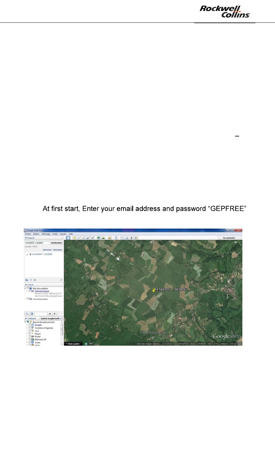
o
o Fin the place where you want to deploy the PSR-500 system
Figure 7: Locate the zone with Google Earth
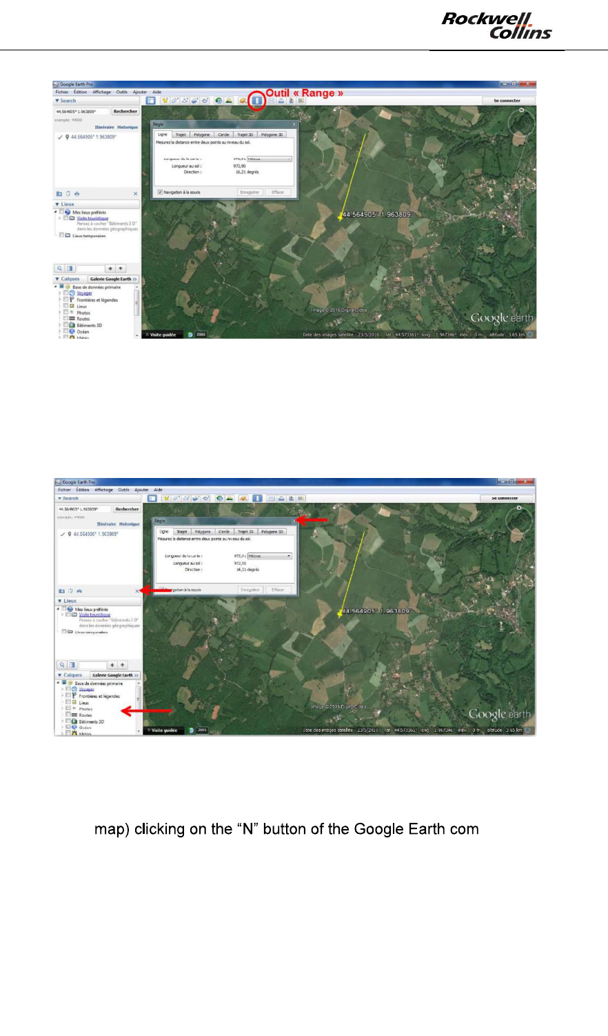
o Use the « range tool » to ensure that the current zoom factor is enough
to get at least 900m (PSR instrumented range) around the position
where you plan to deploy the PSR. Indeed, Google Earth pro will only
extract the map corresponding to the current zoom factor. (In case this
is not respected, a part of the alerts raised by some radars may not be
displayed on the map):
PSR-500 System Installation Guide
Page 21 / 125
CPN 222-3044-657 Rev B CAGEC F5491 Rockwell Collins - Proprietary Information
Figure 8: Google Earth scale factor
o Close the result of your research and any overlay option to minimize
the number of indications on the map you will extract. Purpose is to get
a map as clean as possible for extraction. Alerts raised by radars will be
displayed on this map.
Figure 9: Close Option menus of Google Earth
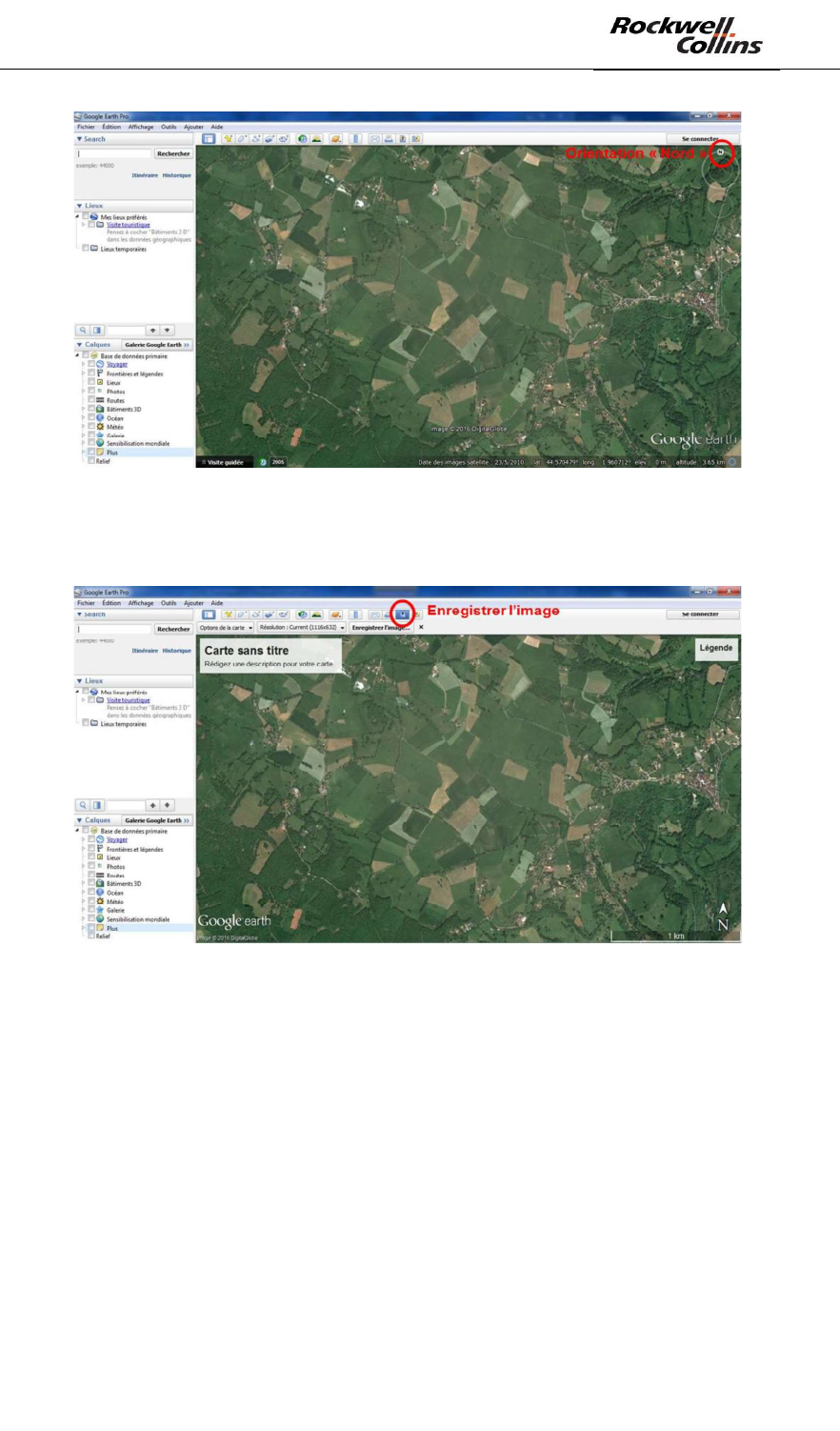
o As previously mentioned, the PSR-500 Installer needs North oriented
maps. Ensure the map is North oriented (i.e. North on the top of the
pass.
Warning: Google Earth extract function takes the map as it is at the
moment of extraction.
PSR-500 System Installation Guide
Page 22 / 125
CPN 222-3044-657 Rev B CAGEC F5491 Rockwell Collins - Proprietary Information
Figure 10: Google Earth map Nord oriented
o Click on the « Save map» button
Figure 11: Save picture on Google Earth
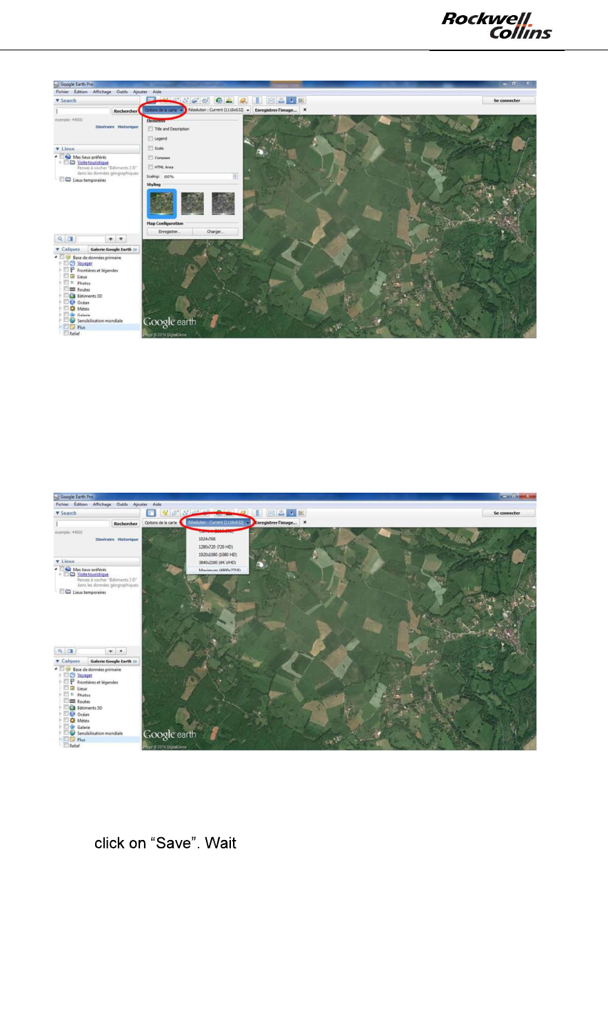
o Unselect all overlaid options of the map clicking on « map options » so
the map remains as clean as possible from any indication.
PSR-500 System Installation Guide
Page 23 / 125
CPN 222-3044-657 Rev B CAGEC F5491 Rockwell Collins - Proprietary Information
Figure 12: Unselect display options of Google Earth
o Select the highest resolution. Doing that, a high level of detail will
remain even if you zoom in once in the PSR-500 Installer application. A
high resolution is also necessary to have a precise deployment of each
radar and therefore a higher accuracy of the geographical position of
the alerts.
Figure 13: Selection of the picture resolution on Google Earth
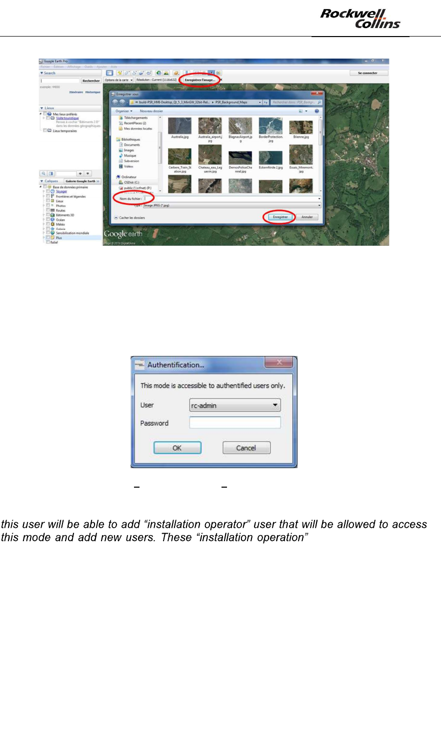
o Save the map in the appropriate PSR-500 Installer directory (<PSR-
500_Installer_Directory>\PSR_Background_Maps). Name the map and
for the download to be completed.
o
PSR-500 System Installation Guide
Page 24 / 125
CPN 222-3044-657 Rev B CAGEC F5491 Rockwell Collins - Proprietary Information
Figure 14: Save the map
6.1.1.2. Define map references in PSR-500 Installer application
- Start the PSR-500 Installer application, double clicking on application
executable (PSR-500_Installer.exe)
- Enter a user login and a password.
Figure 15 PSR-500 Installer Authentification window
Note: By default, on Super-user can access this mode. Once first install performed,
users will be proposed
in the drop-down menu of this window.
- Super-user credentials are the following :
o User = rc-admin
o Password = rcf_admin_31
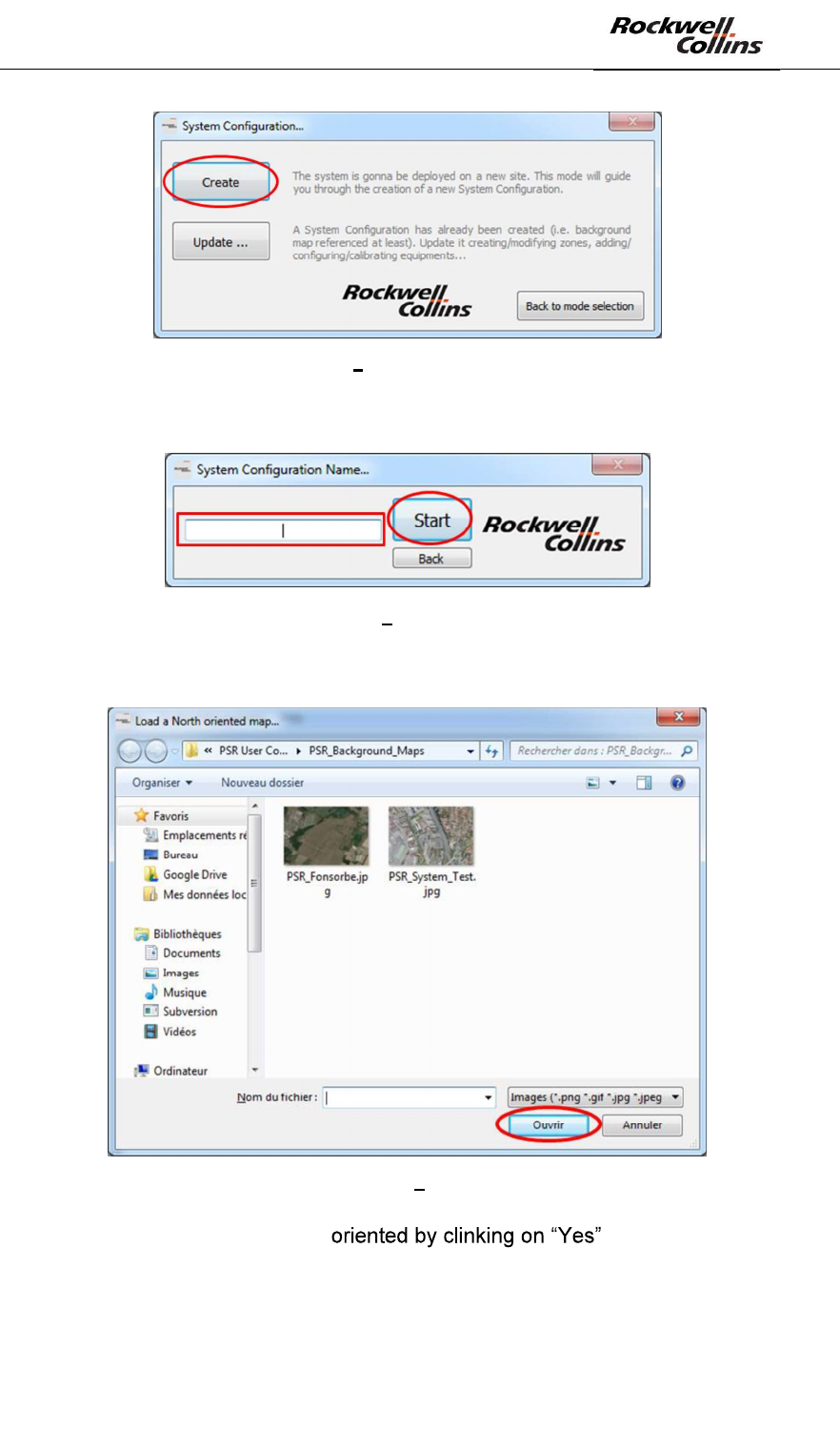
- In the next window, user can either create or modify a system configuration.
Click on Create in the « System Configuration » window to start the creation of a
new system configuration.
PSR-500 System Installation Guide
Page 25 / 125
CPN 222-3044-657 Rev B CAGEC F5491 Rockwell Collins - Proprietary Information
Figure 16: PSR-500 Installer Creation of a new system configuration
- Provide a name for this new system configuration and click on « Start »
Figure 17: PSR-500 Installer New System configuration name
- Select the map you want to use and click on « Open »
Figure 18: PSR-500 Installer Select Google Earth map
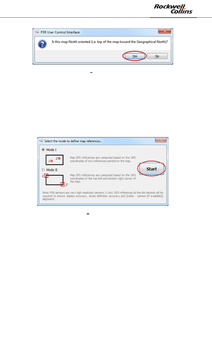
- Confirm that the map is north-
PSR-500 System Installation Guide
Page 26 / 125
CPN 222-3044-657 Rev B CAGEC F5491 Rockwell Collins - Proprietary Information
Figure 19: PSR-500 Installer Confirm that the map is north-oriented
- Define map references with two known GPS coordinates. Two modes are
proposed to define map references the background map :
o Mode I = based on GPS coordinates of two references pointed on the
map
o Mode II = based on the GPS coordinates of the top left and bottom right
corner of the map
- In our example, we follow mode I. Select Mode I if not already selected and click
on « Start »
Figure 20: PSR-500 Installer Select the mode to define map references
Note that references at the 6th decimal will be required according to PSR Sensors
Units high resolution (1.5m). This reference definition phase has to be as much as
precise as possible unless locations of alerts will not be positioned accurately on the
map.
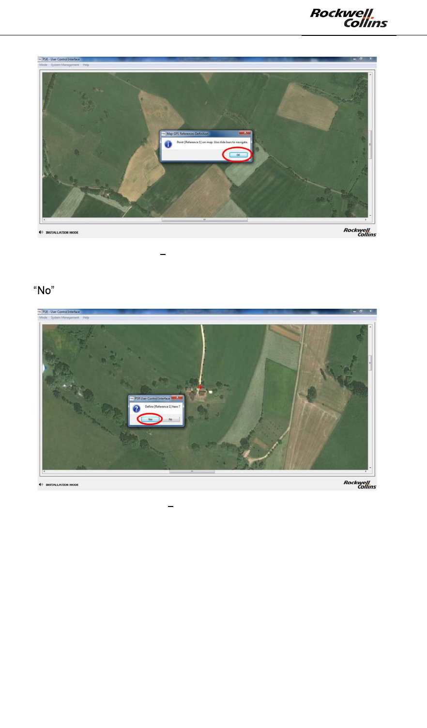
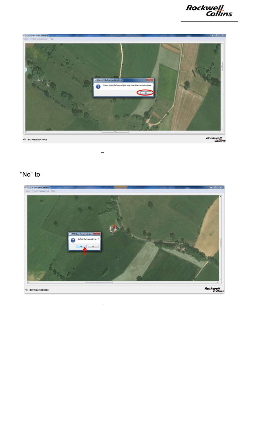
- Identify the point [Reference 1] by clinking on « OK », zoom in to be as precise
as possible and define it on the map clicking on it. Use horizontal and vertical
scroll bars to navigate on the map. Any click on the map will be taken by the
application as the designation of the requested reference.
PSR-500 System Installation Guide
Page 27 / 125
CPN 222-3044-657 Rev B CAGEC F5491 Rockwell Collins - Proprietary Information
Figure 21: PSR-500 Installer Identification of point [Reference 1] on PSR map
- Click « Yes » to confirm point [Reference 1]. If you get the wrong point, click
to come back to previous step.
Figure 22: PSR-500 Installer Validation du point [Reference 1] sur la carte
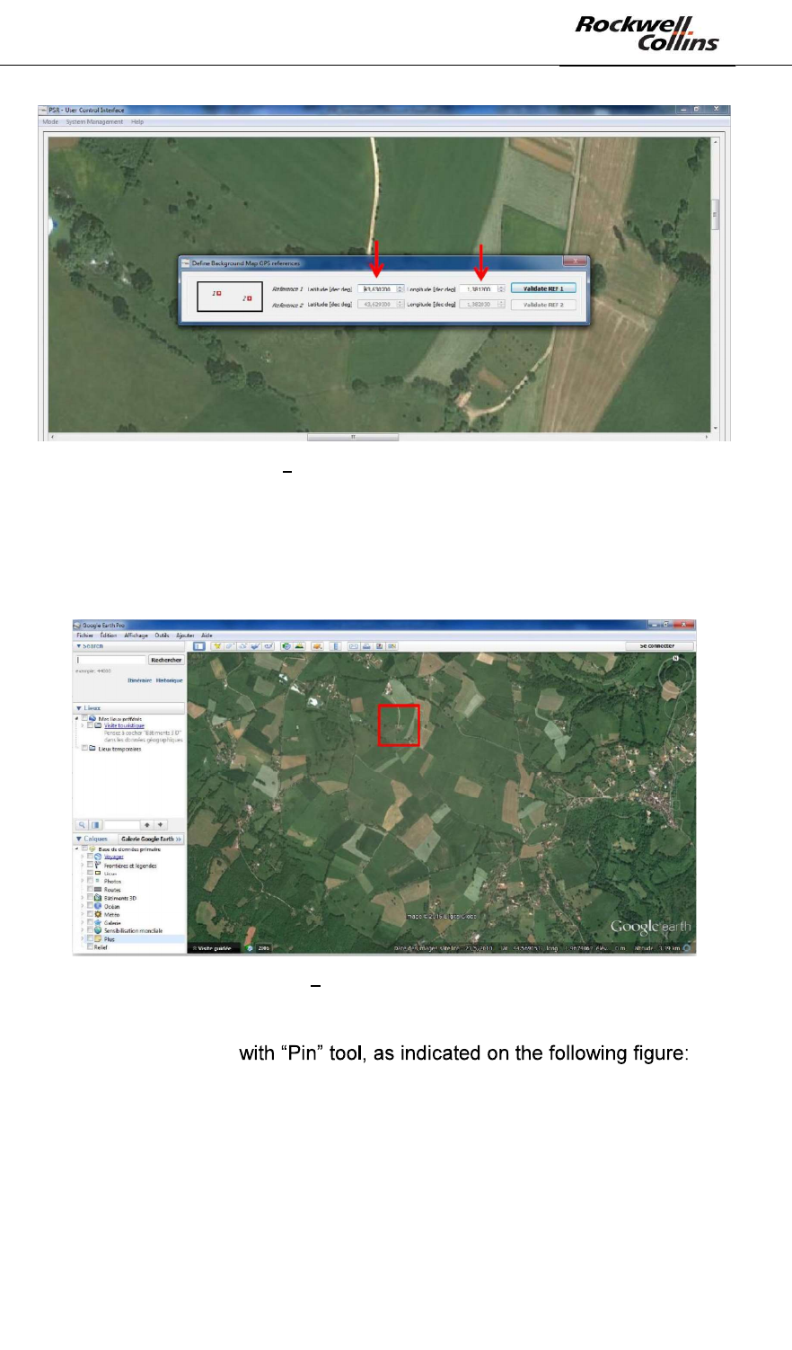
- You must now enter GPS coordinates of point [Reference 1] (latitude and
longitude).
PSR-500 System Installation Guide
Page 28 / 125
CPN 222-3044-657 Rev B CAGEC F5491 Rockwell Collins - Proprietary Information
Figure 23: PSR-500 Installer Enter GPS latitude / longitude of point [Reference 1]
- If you imported your own map, you should already know coordinates of the
point. Register then as indicated in Figure 23. If you import your map from
Google Earth, locate the point [Reference 1] on Google Earth map, as
indicated on the following figure :
Figure 24: PSR-500 Installer Localize point [Reference 1] on Google Earth
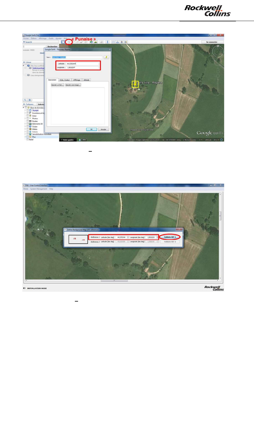
- Zoom in (to be as precise as possible) and recover the GPS coordinates of
point [Reference 1]
PSR-500 System Installation Guide
Page 29 / 125
CPN 222-3044-657 Rev B CAGEC F5491 Rockwell Collins - Proprietary Information
Figure 25: PSR-500 Installer Get GPS coordinate with « pin » tool on Google Earth
- Getting back to PSR-500 Installer, enter the GPS coordinates of point
[Reference 1] and click on « Validate REF 1 » :
Figure 26: PSR-500 Installer Validation of GPS coordinates of point [Reference 1] on the map
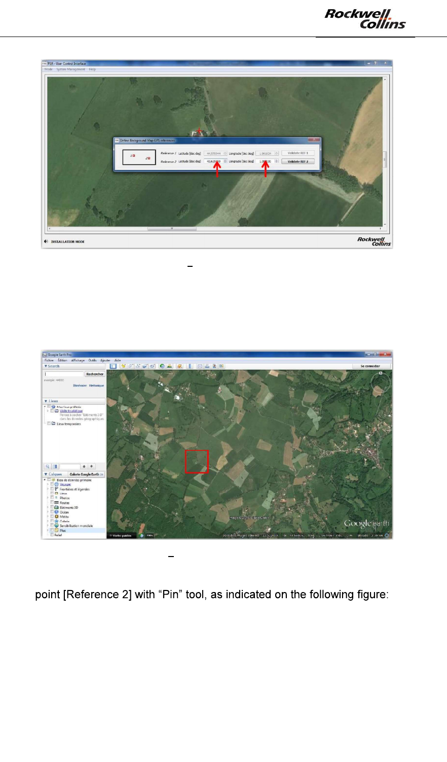
- Click on « OK » to identify point [Reference 2], zoom in to be as precise as
possible and define it on the map clicking on it. Use horizontal and vertical
scroll bars to move over the map.
PSR-500 System Installation Guide
Page 30 / 125
CPN 222-3044-657 Rev B CAGEC F5491 Rockwell Collins - Proprietary Information
Figure 27: PSR-500 Installer Identify point [Reference 2] on the PSR map
- Click « Yes » to validate point [Reference 2]. If you get the wrong point, click
come back to previous step.
Figure 28: PSR-500 Installer Validation of point [Reference 2] on PSR map
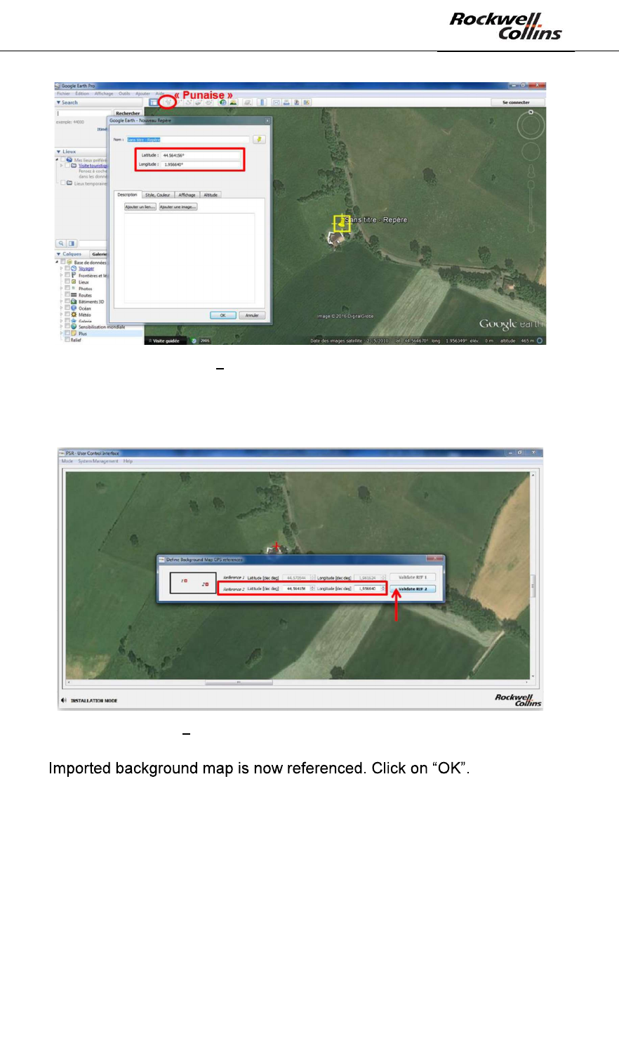
- You must now enter GPS coordinates of point [Reference 2] (latitude and
longitude).
PSR-500 System Installation Guide
Page 31 / 125
CPN 222-3044-657 Rev B CAGEC F5491 Rockwell Collins - Proprietary Information
Figure 29: PSR-500 Installer Save coordinates of point [Reference 2]
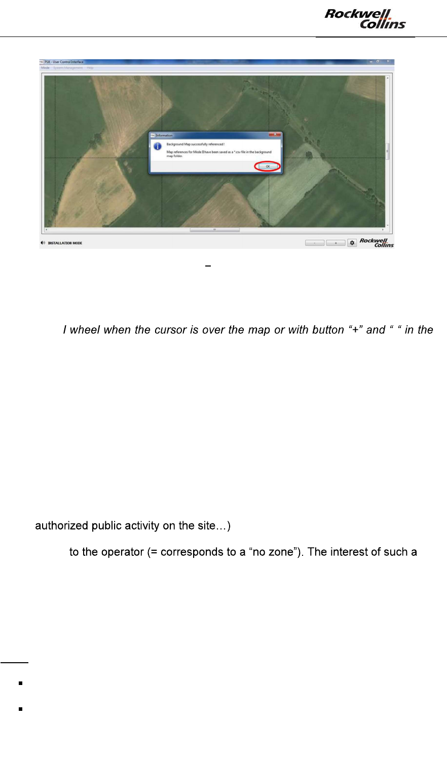
- If you imported your own map, you should already know coordinates of the
point. Register then as indicated in Figure 29. If you import your map from
Google Earth, locate the point [Reference 2] on Google Earth map, as
indicated on the following figure :
Figure 30: PSR-500 Installer localize the point [Reference 2] on Google Earth
- Zoom in (to be as precise as possible) and recover the GPS coordinates of
PSR-500 System Installation Guide
Page 32 / 125
CPN 222-3044-657 Rev B CAGEC F5491 Rockwell Collins - Proprietary Information
Figure 31: PSR-500 Installer Get GPS coordinate with « pin » tool on Google Earth
- Getting back to PSR-500 Installer, enter the GPS coordinates of point
[Reference 2] and click on « Validate REF 2» :
Figure 32: PSR-500 Installer Validation of GPS coordinates of point [Reference 2] on the map
-
PSR-500 System Installation Guide
Page 33 / 125
CPN 222-3044-657 Rev B CAGEC F5491 Rockwell Collins - Proprietary Information
Figure 33: PSR-500 Installer Map references correctly set up
Note: the navigation on the background map can either be done with the horizontal
and vertical scroll bars or by keeping the mouse left button pressed at one point of
the map and moving the mouse. The zoom level can be set up either through the
mouse scrol -
bottom right-hand corner of the window.
6.1.2. Step#2 : Define site surveillance
The application automatically passes to this step at the end of step#1.
Before moving on to this phase, the installation operator shall be able to answer the
following questions:
- How must be organized the surveillance of the site? Which zones must be
secured?
- Is there any highly sensitive location and what would be the trajectories of the
intrusions?
- Is there any area where the access is more critical than others? i.e. is there a
reason to define two levels of alerts (caution and warning) ?
- Is there any area that the radar(s) deployed will have to ignore? (any
o Have the radar to still monitor these zone but without raising any alert
setting is the reactivity of the system will be maximized in case of
entrance into a forbidden zone.
o Do we have to create exclusion zone(s) to avoid alerts on authorized
and known activities? The interest of such a setting is to limit false
alarms that may be raised at the edge of forest made of big branch
trees.
Note:
No zone = Complete radar processing is performed BUT no information is
forwarded toward the operator.
Exclusion zone : Radar processing is not performed
PSR-500 System Installation Guide
Page 34 / 125
CPN 222-3044-657 Rev B CAGEC F5491 Rockwell Collins - Proprietary Information
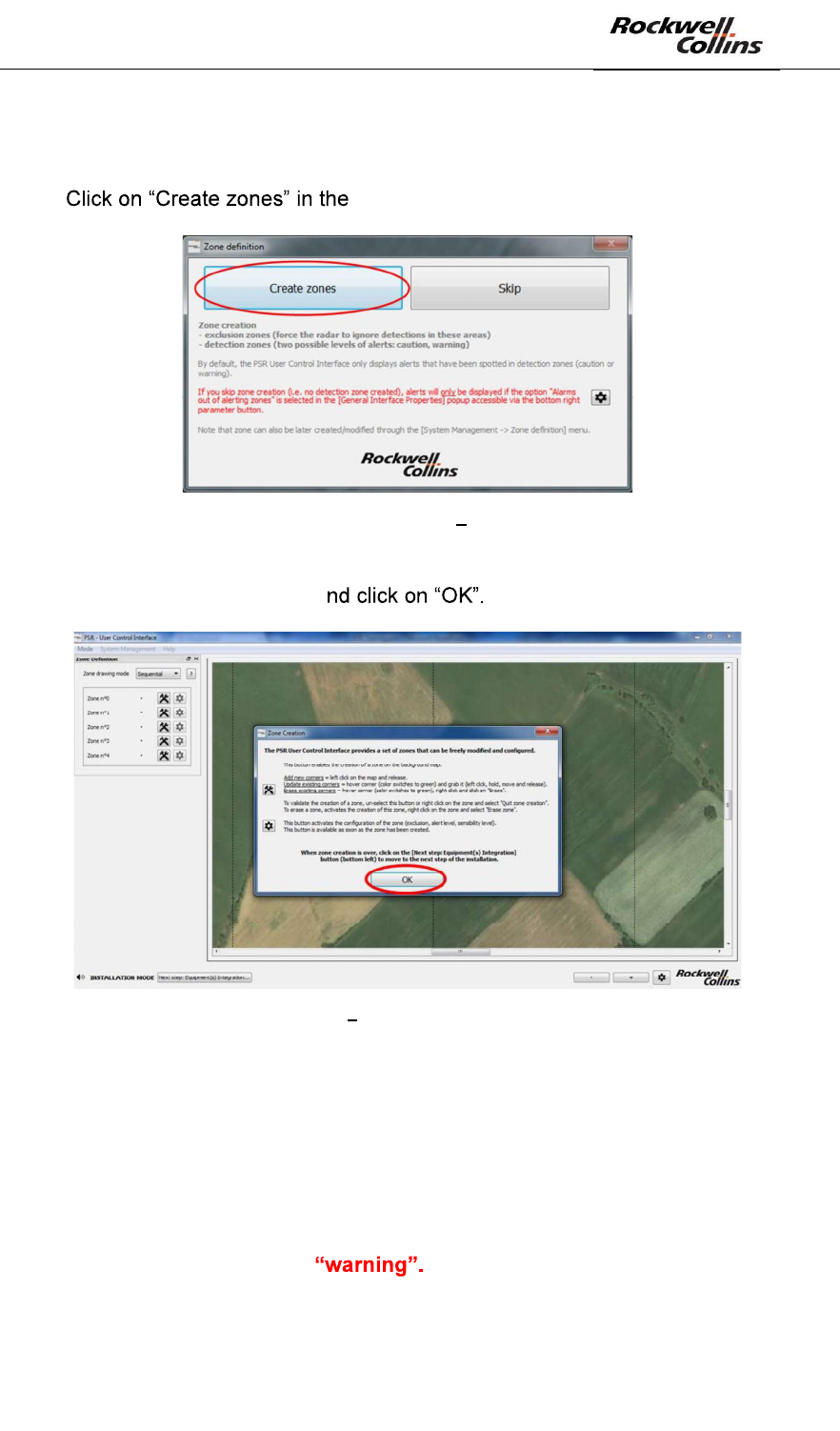
Once all these questions are answered: the creation of zone of surveillance can start.
- « Zone definition » window, cf. image below :
Figure 34: Zone definition Create zones
- Through the displayed popup, read carefully the instructions that explain how
to basically create a zone a
Figure 35: Zone Creation Instructions to follow to create a zone
Note: The PSR-500 Installer application allows creating maximum 50 zones made of
maximum 50 points each. One can create alerting zones (two levels are proposed)
and exclusion zones.
Note : as previously explained, the PSR-500 system will only alerts if intrusion are
located in an alerting zone. If the operator chose not to create any alerting zone, no
intrusion alerts will be raised by the deployed radars.
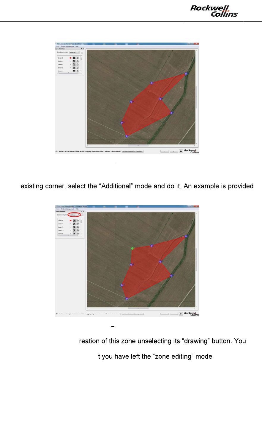
- Creation of a first zone. By default, a new zone is a detection zone with the
highest alerting level i.e. By default, the « sequential » mode is
activated meaning that each time you click on the map, a new corner will be
added sequentially, whatever the position of the click. In this mode, you can
not add a corner between two existing corners.
PSR-500 System Installation Guide
Page 35 / 125
CPN 222-3044-657 Rev B CAGEC F5491 Rockwell Collins - Proprietary Information
Figure 36: PSR-500 Installer Creation of a first zone of surveillance
- If you need to refine the shape of a zone and add a corner between two
below with corner n°2
Figure 37: PSR-500 Installer Add a point in an already defined zone
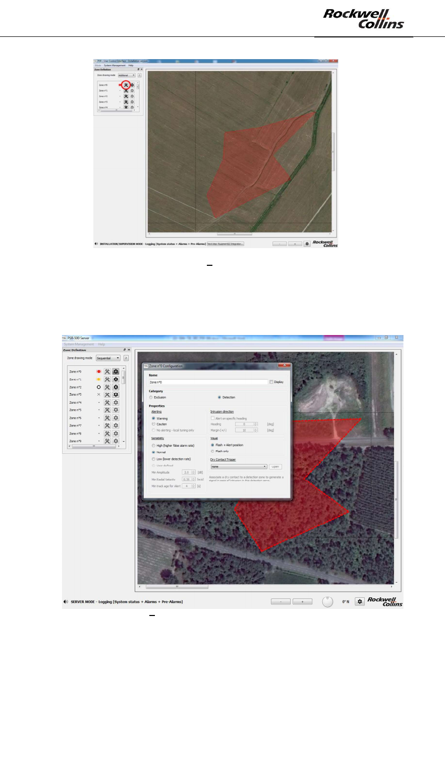
- We now leave the c
can see that the corners have disappeared and that the color of the zone is
less bright. It indicates tha
PSR-500 System Installation Guide
Page 36 / 125
CPN 222-3044-657 Rev B CAGEC F5491 Rockwell Collins - Proprietary Information
Figure 38: PSR-500 Installer Exit of the zone creation mode
- To configure the properties of this zone, click on its « parameter » button as
shown below. The zone is highlighted, indicating that parameters modification
is in progress.
Figure 39: PSR-500 Installer Configuration of the properties of the surveillance zone.
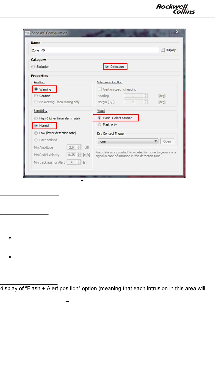
- In our example, the following parameters are selected :
PSR-500 System Installation Guide
Page 37 / 125
CPN 222-3044-657 Rev B CAGEC F5491 Rockwell Collins - Proprietary Information
Figure 40: PSR-500 Installer Configuration parameters of a surveillance zone
Note on alerting levels: two alerting levels are proposed to allow the operator to tune
the site surveillance.
Note on sensibility: three levels are proposed. These levels will impact how each
radar monitoring this area will filter detections: in minimum amplitude, in minimum
radial velocity, and in minimum track age for alert
The highest sensibility, the lowest parameters. The advantage is an increase
of the detection probability, and the drawback is an increase of the false alarm
probability.
The lowest sensibility, the highest parameters. The drawback is a decrease of
the detection probability, and the advantage is a decrease of the false alarm
probability.
Note sur visual aspect : in our example, the zone is large enough to maintain the
be displayed as a triangle at the exact location of the intrusion and the zone
background color will blink flash only means that only the zone background color
would blink it can be useful to clean the display in case of small zones / dense
activity).
- Create a caution zone next to the previous warning zone and an exclusion
zone inside the warning zone:
PSR-500 System Installation Guide
Page 38 / 125
CPN 222-3044-657 Rev B CAGEC F5491 Rockwell Collins - Proprietary Information
Figure 41: PSR-500 Installer Addition of a caution zone and an exclusion zone
Note on zones:
Exclusion zone prevails on any detection zone
Warning zone prevails on caution zone
Regarding the sensibility
- The highest amplitude limit prevails
- The highest radial velocity prevails
- The lowest track age for alert prevails
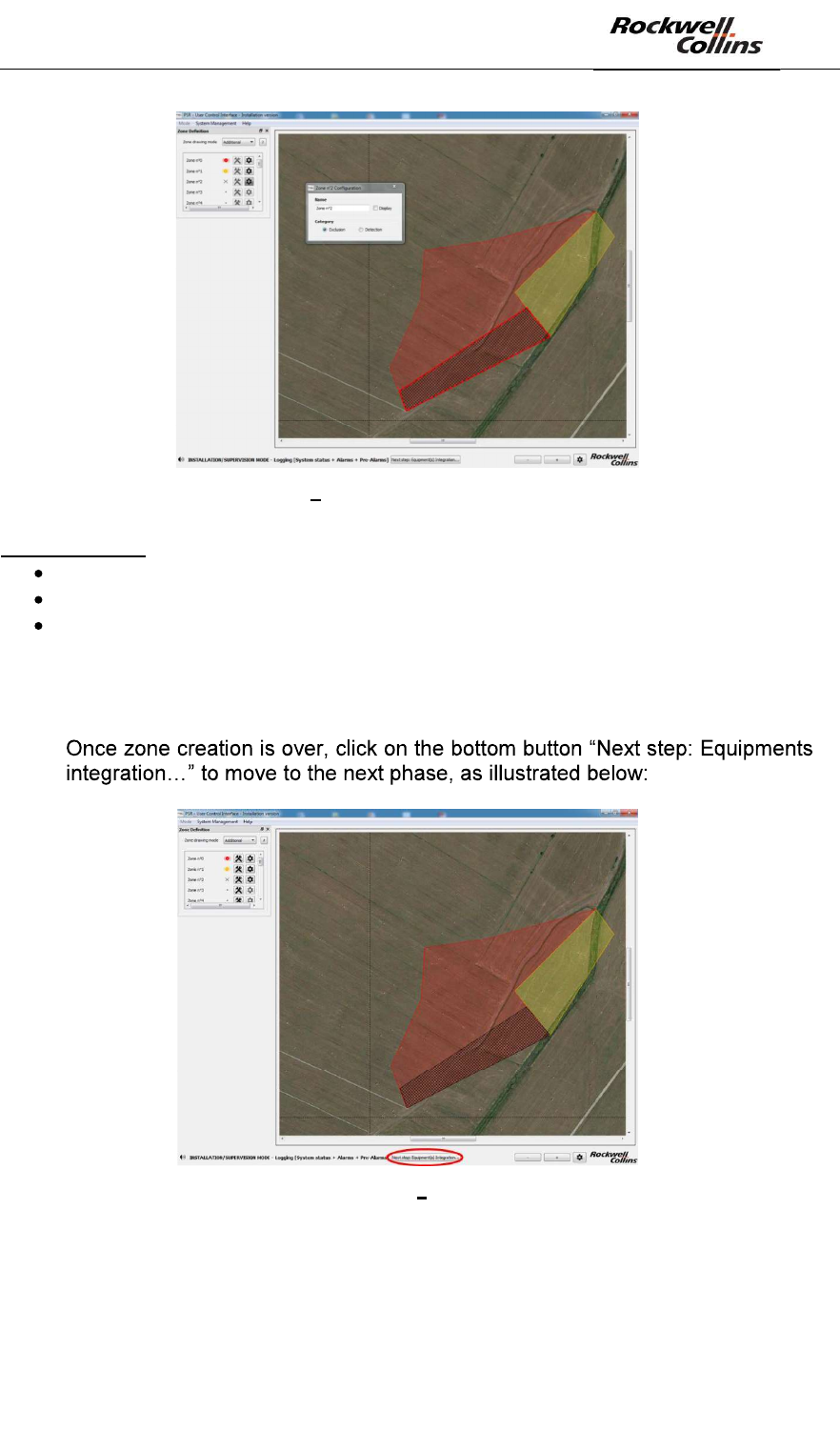
-
Figure 42: PSR-500 Installer End of the zone creation
Association with a potential Dry Contact is treated in Step#5.
PSR-500 System Installation Guide
Page 39 / 125
CPN 222-3044-657 Rev B CAGEC F5491 Rockwell Collins - Proprietary Information
6.1.3. Step#3: Add, position and configure one or several radars (SU+PU)
The next step consists in adding, positioning and configuring one or several radars to
better cover these areas.
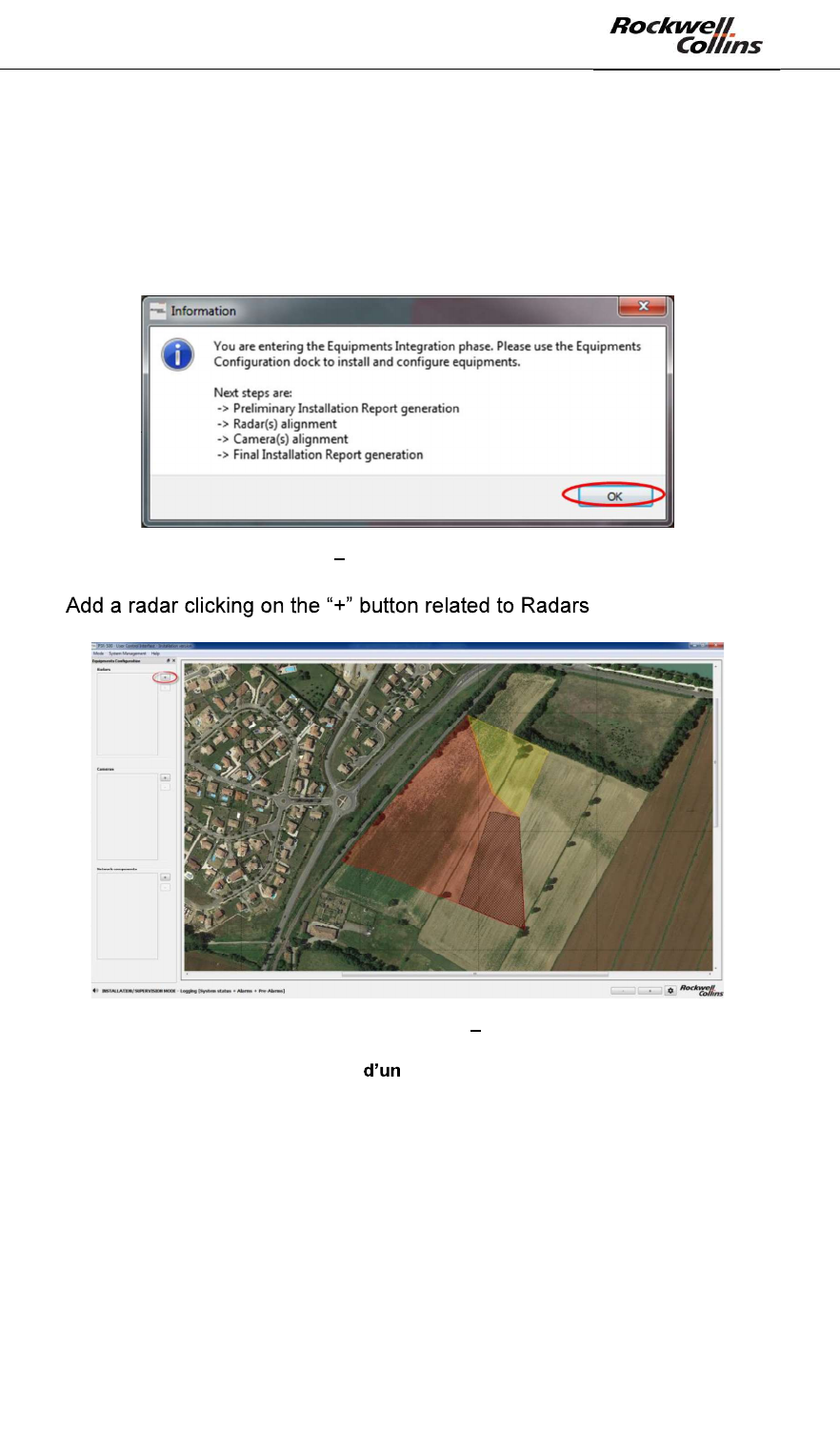
- Click on « OK » in the « Information » window that automatically opens at the
end of step#2.
Figure 43: PSR-500 Installer « Information » window at the end of step#2
- (see below):
Figure 44: PSR-500 Installer Add a radar
6.1.3.1. Rappels sur la technologie radar Doppler
In order to maximize the detection performances of a PSR-500 System radar, it is
necessary to understand some basics of Doppler radar technology.
Detection performances of a Doppler radar system are a trade-off (gain, loss) among
many parameters. We call it link budget. This « link budget » will define the contrast
of the target within its environment (environment noise and system noise).
The link budget inputs are:
- Radar & Signal processing characteristics
PSR-500 System Installation Guide
Page 40 / 125
CPN 222-3044-657 Rev B CAGEC F5491 Rockwell Collins - Proprietary Information
- Antenna radiation pattern
- Target characteristics
o Position within the antenna radiation pattern
o Range
o Radial velocity (Doppler effect)
o Radar Cross Section (RCS)
The most important concepts to remind:
- Range effect
o The closer a given target is from a radar, the stronger its detectability is
o The farer a given target is from the radar, the weaker its detectability is
- Radiation pattern effect
o The closer a target is from the axis of the antenna of a radar, the
stronger its detectability is
o The farer a target is from the axis of the antenna (on the main axes, in
azimuth and in elevation, e.g. foot of the mast), the weaker its
detectability is
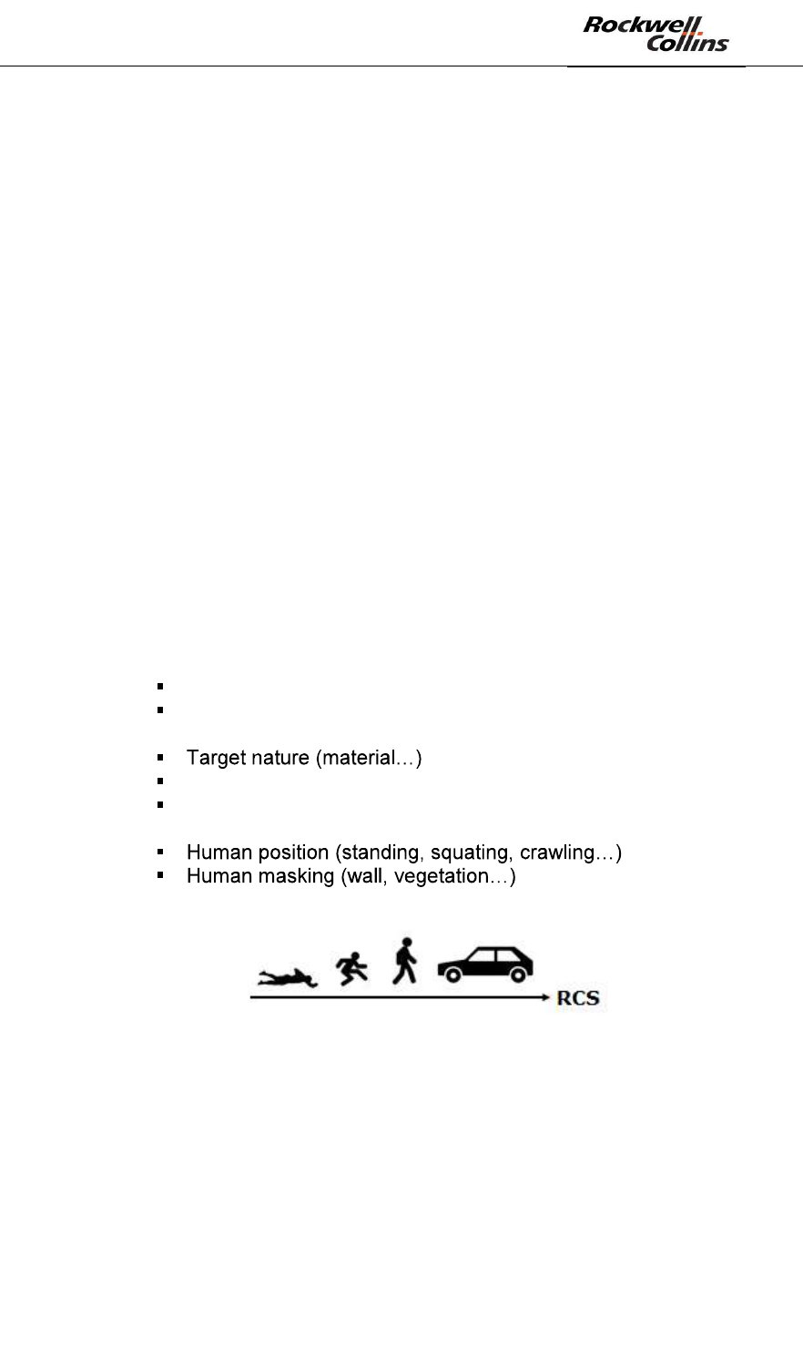
- Radar Cross Section (RCS) effect
o The Radar Cross Section (RCS) is a target property that defines how
much energy a target will backscatter toward a RF source..
o RCS is independent from:
Target range
Target position within antenna radiation pattern
o RCS depends on:
Target shape
Target masking
o Therefore, human intrusion RCS will depend on:
o The stronger the RCS of a target is, the stronger its detectability is
-
Figure 45: RCS evolution depending on the target type
The following figures present the detection zone for a human intrusion (on the left)
and for a car (on the right). Once can see the range, radiation pattern and RCS
effects.