Rockwell Collins 5972410 Perimeter Surveillance Radar User Manual EN 222 3044 657 Installation Guide PSR 500
Rockwell Collins Inc Perimeter Surveillance Radar EN 222 3044 657 Installation Guide PSR 500
Contents
- 1. User Manual 1-40
- 2. User Manual 41-80
- 3. User Manual 81-100
- 4. User Manual 101-125
User Manual 41-80
PSR-500 System Installation Guide
Page 41 / 125
CPN 222-3044-657 Rev B CAGEC F5491 Rockwell Collins - Proprietary Information
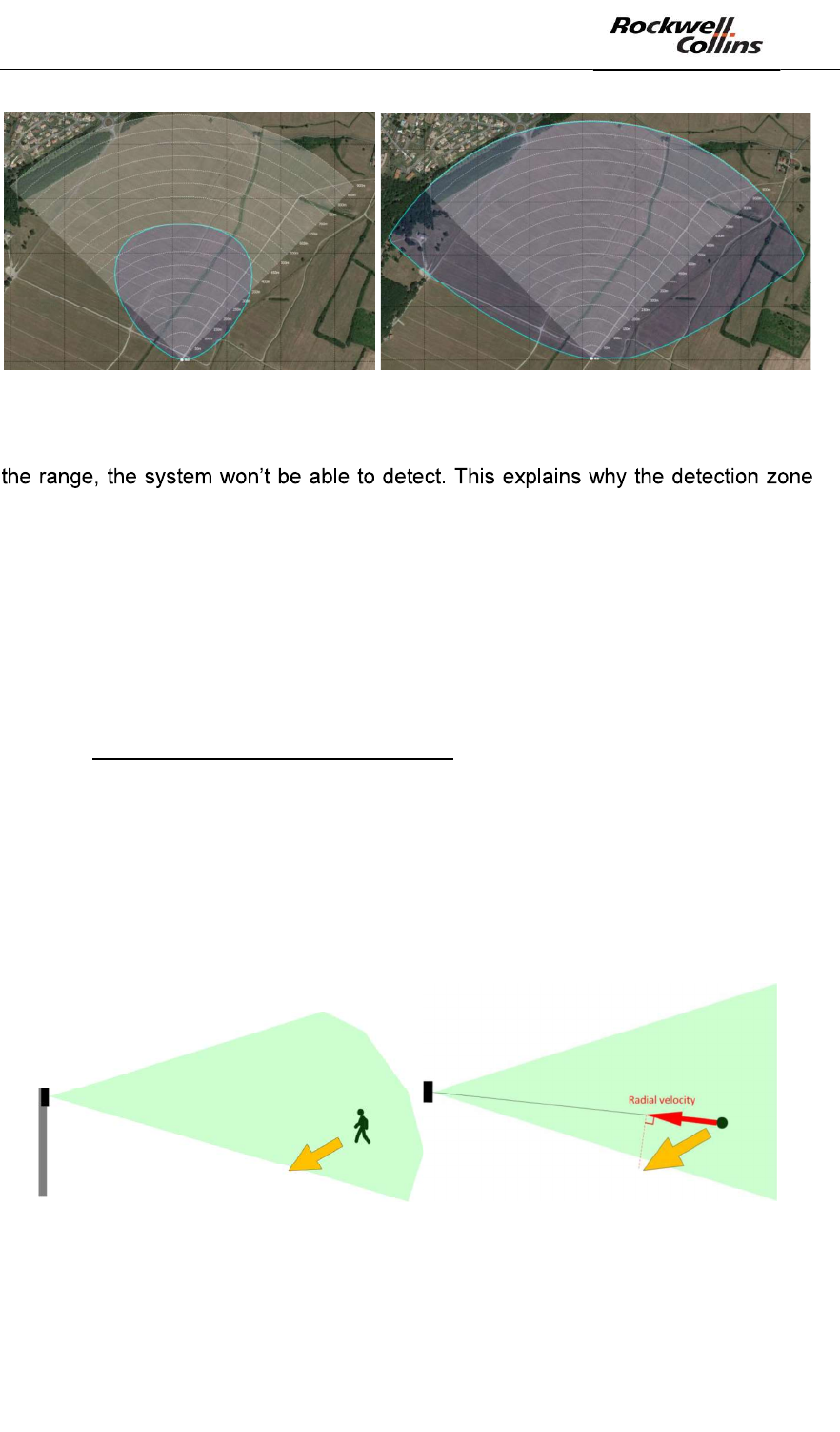
Figure 46: Detection zone for a human intrusion (left) and for a car (right)
Note: the maximum instrumented range of a PSR-500 system radar is 900m. Beyond
for the car seems to be truncated beyond this range.
Note: the PSR-500 Installer assumes that there is no obstacle in the radar coverage
between the target and the radar, and assumes that the radial velocity of the target is
high enough to be detected by the radar.
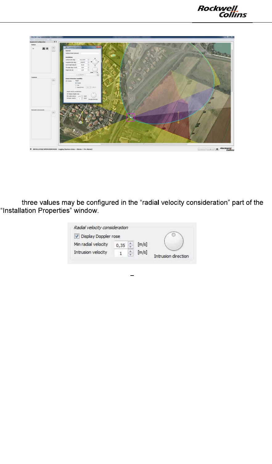
The last concept to remind is the « Doppler effect » on which rely the PSR-500
radars.
While non-Doppler radars compare radar image after radar image to detect motion in
the area, Doppler radars use the Doppler Effect to do so.
The Doppler Effect is an effect visible on the radar signal due to the change of range
of the target within the observation time of the radar. The Doppler effect provides
access to the radial velocity of the targets
The radial velocity of a target is the projection of its absolute velocity of this intrusion
over the straight line from the radar to the intrusion. This projection depends on the
direction and on the speed of the intruder movement:
Figure 47: Illustration radial velocity (3D/2D)
Note: the radial velocity is independent from the sensor orientation.
PSR-500 System Installation Guide
Page 42 / 125
CPN 222-3044-657 Rev B CAGEC F5491 Rockwell Collins - Proprietary Information
Doppler radar technology has been selected for PSR-500 system radars because
this technology is much more efficient to discriminate targets from their surrounding
environment which allows mitigating false alarm rate of the
system. Below a certain radial velocity, the system automatically filters out the
detections.
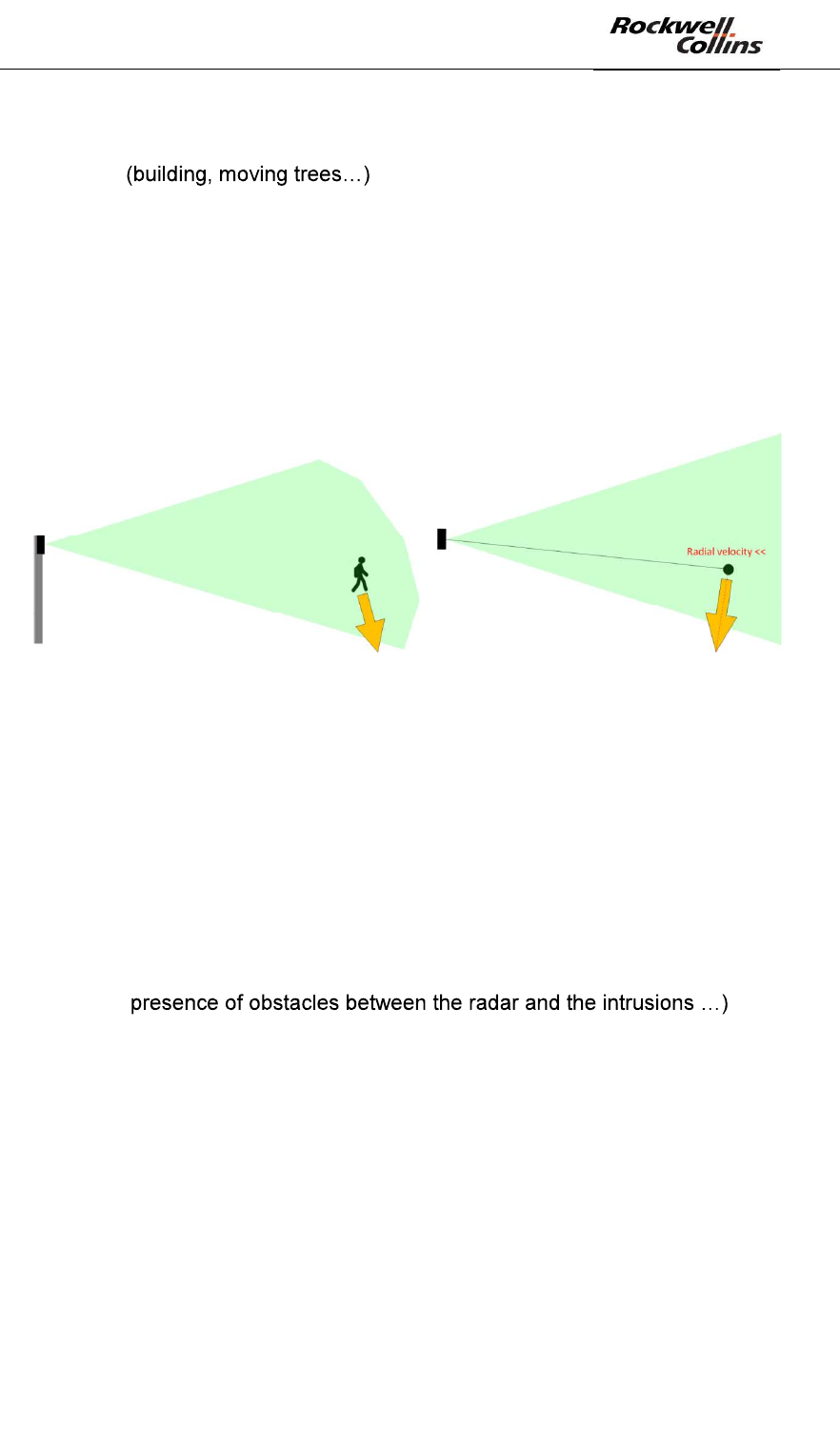
Doppler radar technology implies installation constraints in order to detect human
intrusion with enough radial velocity so that the system does not filter them. One can
consider situations where a moving target shows a low radial velocity to the radar,
such as transverse trajectory. Therefore, to avoid this case, the radar shall de
positioned carefully. This is what we are going to explain in the following section,
helped by an intuitive tool of the PSR-500 Installer.
Figure 48: transverse trajectory case (3D/2D)
6.1.3.2. Position the radar effectively
- Position the radar where you plan to deploy it considering:
o Multi-radar deployment: it is recommended to the installation operator
to read the associated section of this document.
o the zones you previously defined (« Warning », « Caution » and
« Exclusion »)
o The radar coverage area for the detection of human intrusion (blue
zone)
o Potential masking that may limit the detection of intrusion (in case of
o expected intrusion motion (keep in mind that we need to maximize
radial velocity)
PSR-500 System Installation Guide
Page 43 / 125
CPN 222-3044-657 Rev B CAGEC F5491 Rockwell Collins - Proprietary Information
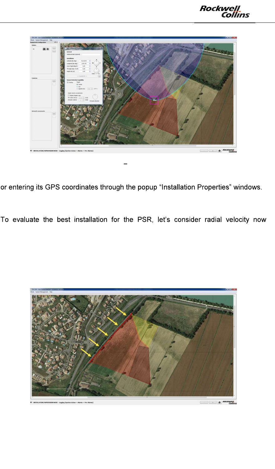
Figure 49: PSR-500 Installer Positioning of a radar on the map
Note: You can move the radar holding the magenta square and moving the mouse,
Similarly, the orientation of the radar can be set up either by modify the value in the
window or by moving the rotating cursor.
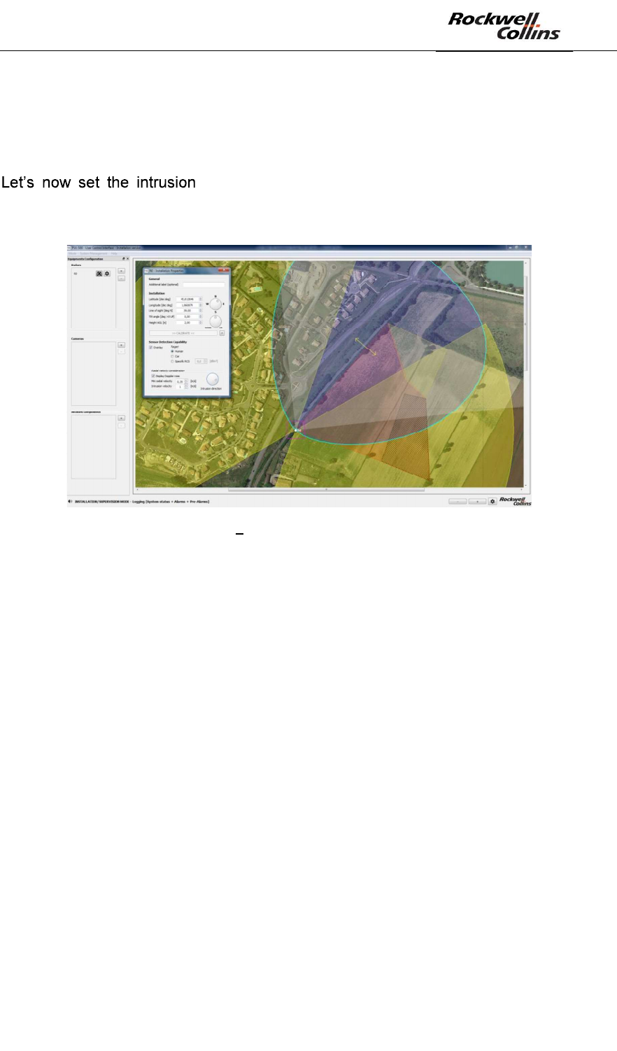
(Doppler Effect). As explained previously, PSR-500 system radars rely on the
Doppler Effect to discriminate an intrusion from its environment. Therefore, our
objective is to maximize this effect otherwise the radar may miss some intrusions.
In our example, the expected intrusions are coming from the North West of the site,
through the fence indicated by the red dotted line and by the yellow arrows on the
following figure:
Figure 50: Example on an intrusion scenario on a site
PSR-500 System Installation Guide
Page 44 / 125
CPN 222-3044-657 Rev B CAGEC F5491 Rockwell Collins - Proprietary Information
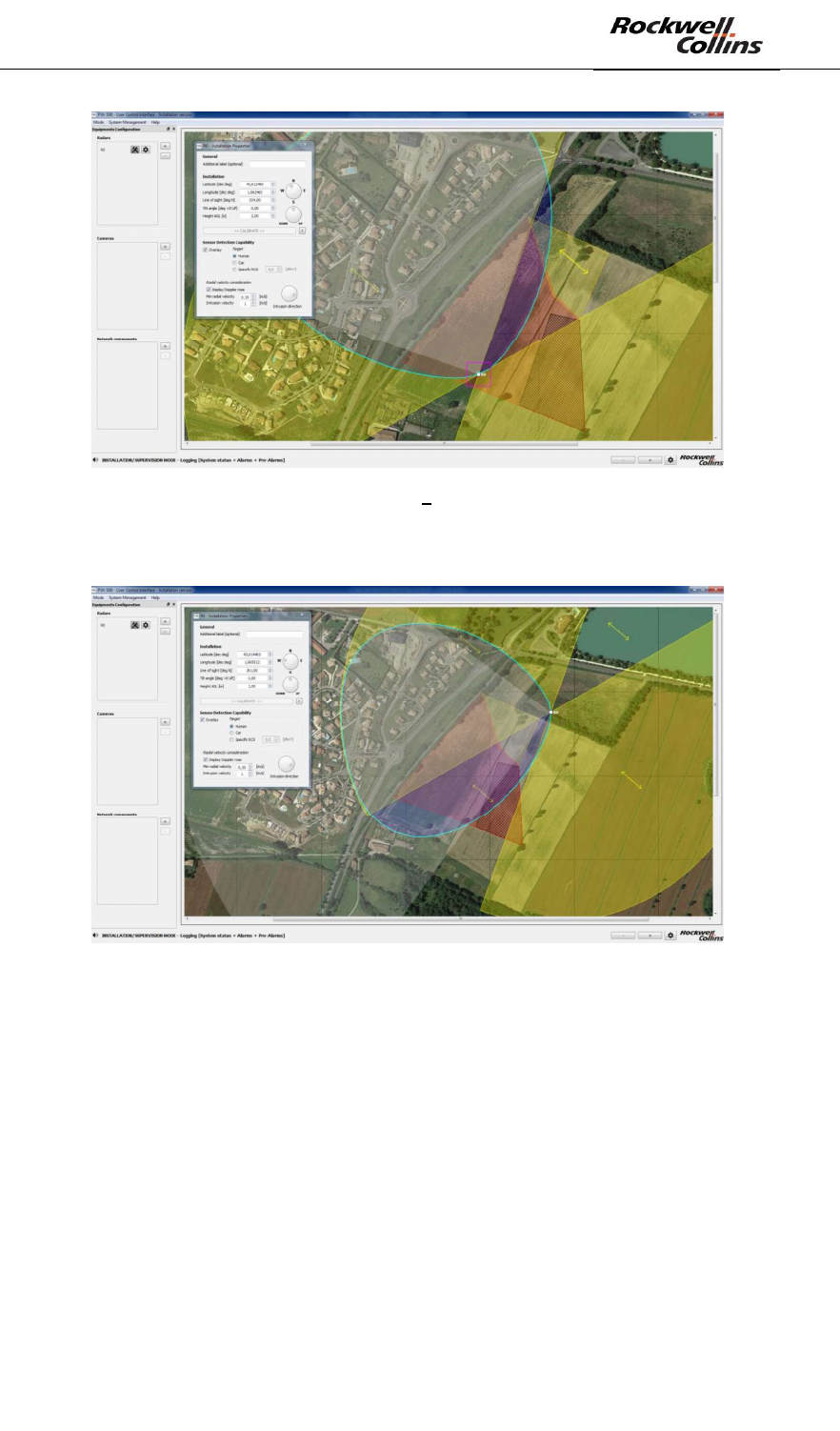
The first idea that may arise to a non-informed operator would be to position the
radar over the fence so that the radar coverage (blue pattern) covers entirely the
fence.
Figure 51: Not recommended radar installation
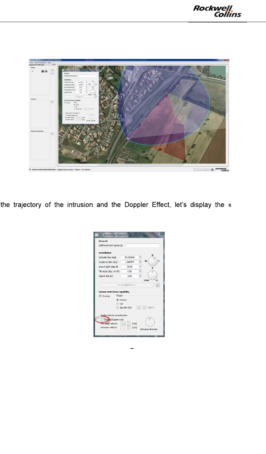
In order to see why this type of installation is not recommended taken into account
Doppler
Rose ». Click on the « Display Rose Doppler » button of the Installation properties
window of the radar in deployment.
Figure 52: PSR-500 Installer Display the Doppler Rose
PSR-500 System Installation Guide
Page 45 / 125
CPN 222-3044-657 Rev B CAGEC F5491 Rockwell Collins - Proprietary Information
Figure 53: PSR-500 Installer - Doppler Rose displayed
The Doppler rose is the yellow area that tells you where the radar will measure more
than [min radial velocity] according to the [intrusion velocity] and the [intrusion
motion] (yellow arrows).
These
Figure 54: PSR-500 Installer Setting of the Doppler Rose
The « Doppler Rose » takes into account the following properties:
- Absolute velocity of the intrusion
- Intrusion direction
- Minimal radio velocity of the radar
By default, the values of these properties are the following one:
- Absolute velocity of the intrusion = 1m/s (normal walking velocity)
- Intrusion direction = North/South & South/North trajectories. The direction is
shown by the yellow arrows.
- Min radial velocity = 0.35 m/s (PSR normal sensibility)
Note on the « Rose Doppler » configuration:
- Increase absolute velocity of the intrusion will increase yellow area coverage
since the radar will perceive a minimum radial velocity of 0.35m/s in more
areas
PSR-500 System Installation Guide
Page 46 / 125
CPN 222-3044-657 Rev B CAGEC F5491 Rockwell Collins - Proprietary Information
- The orientation of the « Doppler Rose » depends directly on the intrusion
direction.
- Decrease minimum radial velocity will increase yellow area coverage since teh
radar will perceive the minimum radial velocity in more areas.
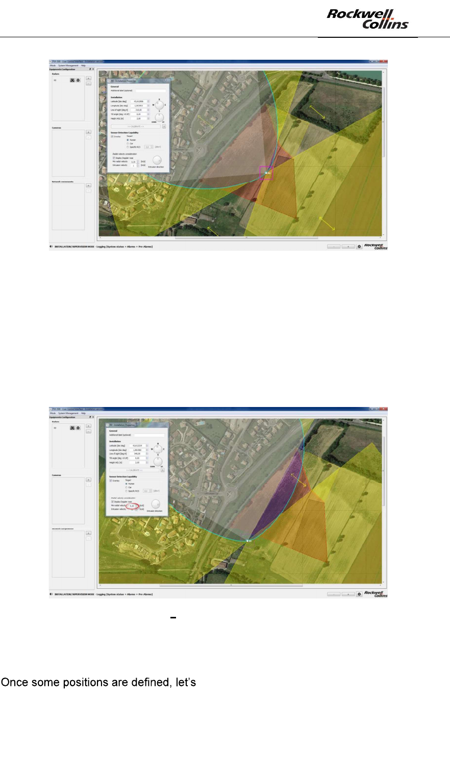
motion angle according to the expected threat on the
North West fence: Turn the Intrusion motion button to align the yellow arrows of the
« Doppler Rose » with the intrusion direction.
Figure 55: PSR-500 Installer Doppler Rose aligned with expected intrusions
To ensure protection, the area of interest must be both in the blue area (radar
coverage) and in the Yellow area (zone with enough radial velocity).
The « hole » in the Doppler zone (Yellow) over the fence underlines the fact that due
to the radar position, the intrusion velocity (1m/s) and the sensibility of the zone
(normal = 0.35m/s), the intrusions in this area will not have enough radial velocity and
will therefore be filtered by the radar; even if the fence is in the coverage area of the
radar (blue zone). Consequently, we must change the radar position.
One solution may be to install the radar inside the site so that the fence is inside the
yellow zone (Doppler zone) and to turn the radar toward the fence, so that its
coverage area overlaps the fence. See below an example of radar position that will
ensure site protection.
PSR-500 System Installation Guide
Page 47 / 125
CPN 222-3044-657 Rev B CAGEC F5491 Rockwell Collins - Proprietary Information
Figure 56: PSR-500 Installer Possible Installation #1
Another example is presented below:
Figure 57: PSR-500 Installer - Possible Installation #2
A third solution is presented below:
PSR-500 System Installation Guide
Page 48 / 125
CPN 222-3044-657 Rev B CAGEC F5491 Rockwell Collins - Proprietary Information
Figure 58: PSR-500 Installer - Possible Installation #3
One can consider many deployments as long as the area to survey is covered both
by the blue and the yellow areas.
If deployment constraints impose to install the radar closer to the fence, one solution
would be to create a local high sensibility area (0.2m/s for the minimum radial
velocity) so the Doppler rose extends a bit.
Figure 59: PSR-500 Installer sensibility increase and possible Installation #4
Nevertheless, this solution shall only be used when no other solution can be found
since it will increase the false alarm probability in this high sensibility zone.
ensure that no obstacle may generate shadow
in the area limiting the detection capability of the radar.
PSR-500 System Installation Guide
Page 49 / 125
CPN 222-3044-657 Rev B CAGEC F5491 Rockwell Collins - Proprietary Information
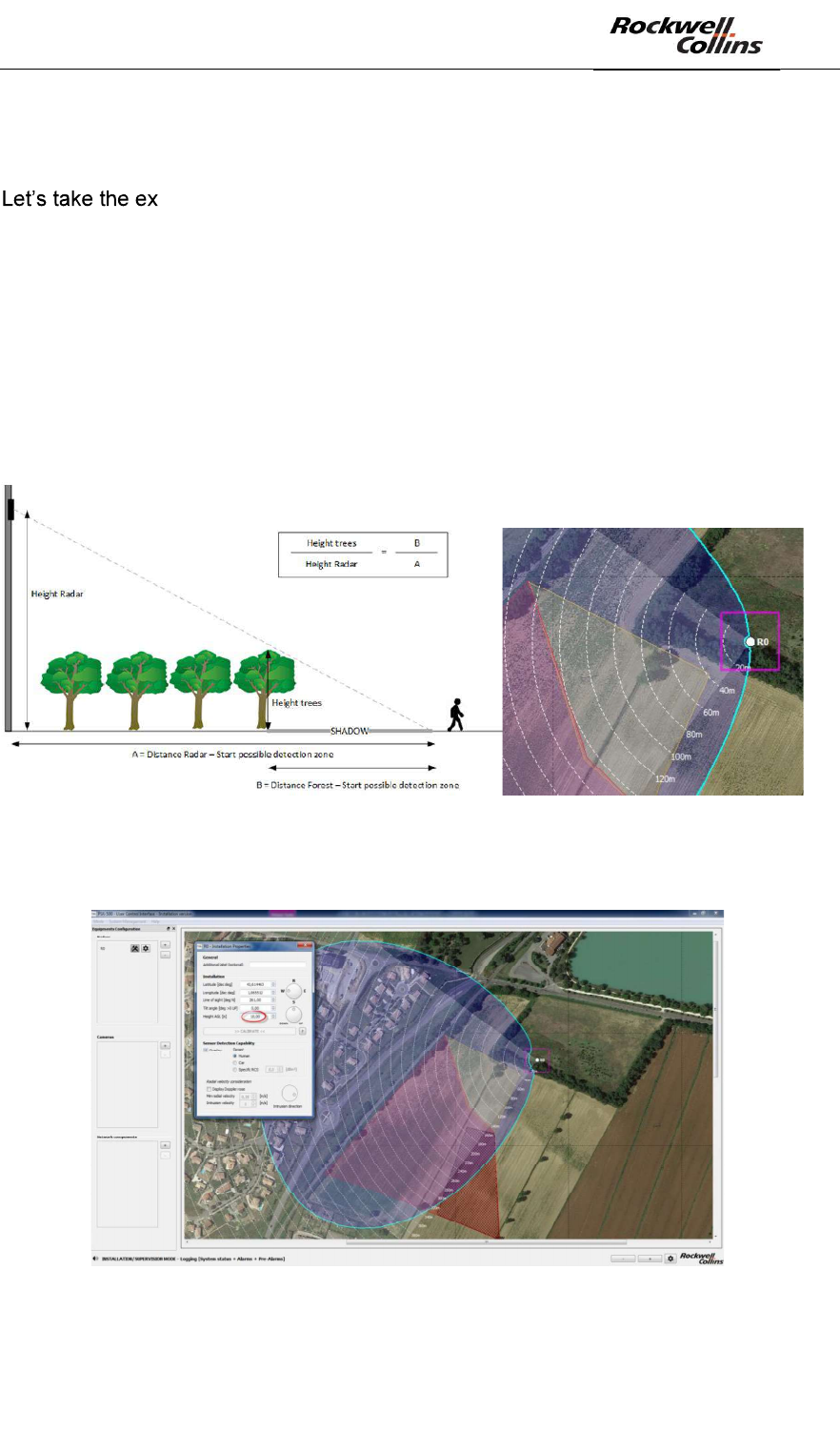
We need to determine the height above the ground at which the radar shall be
installed to taken into account potential obstacles.
ample of possible installation #2:
- The radar would be at 30m away from the beginning of the area to protect (A
value)
- The area to protect would start at 15m away from the end of the forest (B
value)
- The trees are 5m high
The formula provided below tells that the radar needs to be installed at a minimum of
10m above the ground so that the shadow induced does not impact the detection
zone.
Figure 60: Position/height of the radar w.r.t the shadow zone
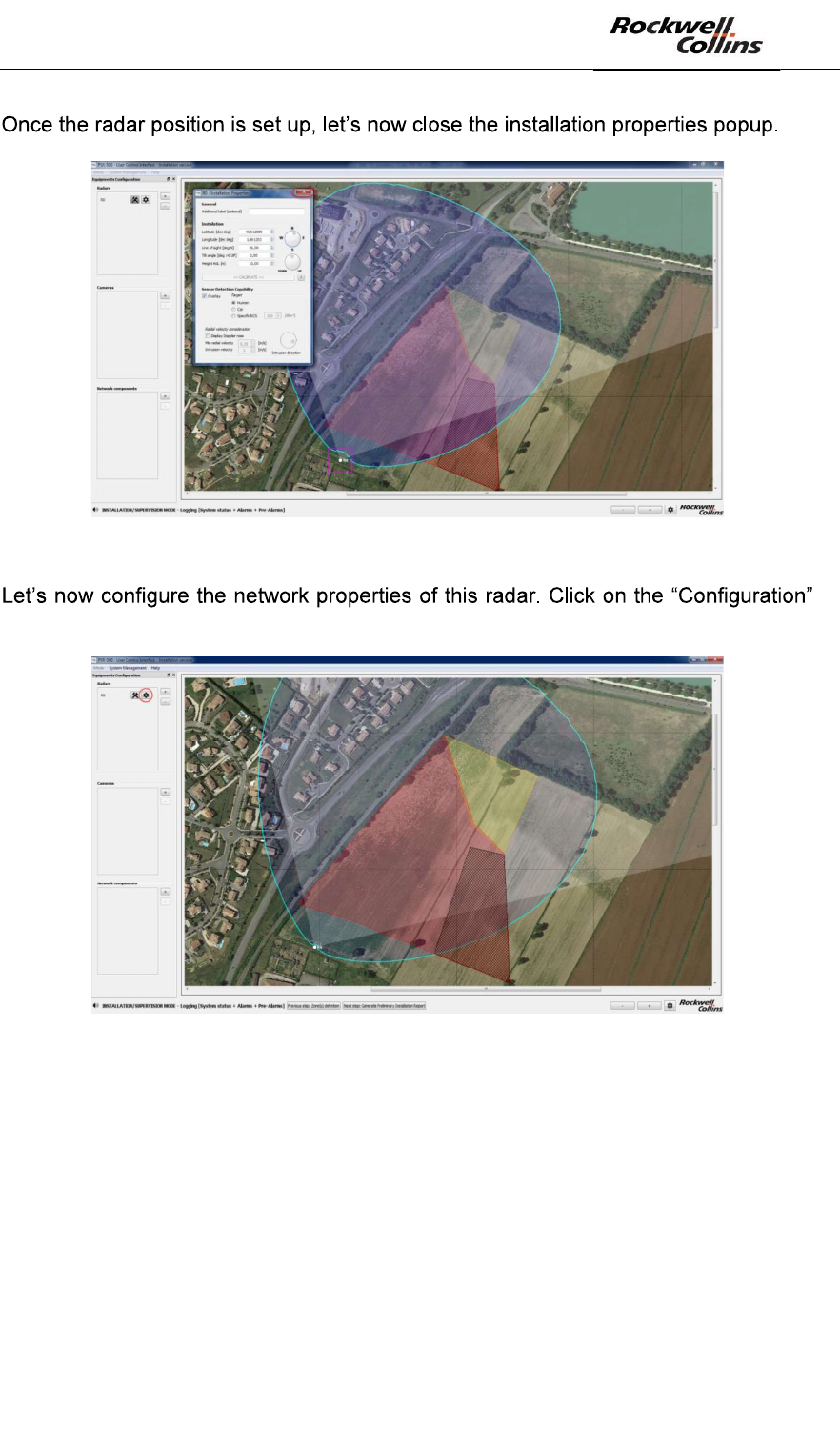
The 10m high shall be set in the radar properties as shown below:
Figure 61: Radar height modification
PSR-500 System Installation Guide
Page 50 / 125
CPN 222-3044-657 Rev B CAGEC F5491 Rockwell Collins - Proprietary Information
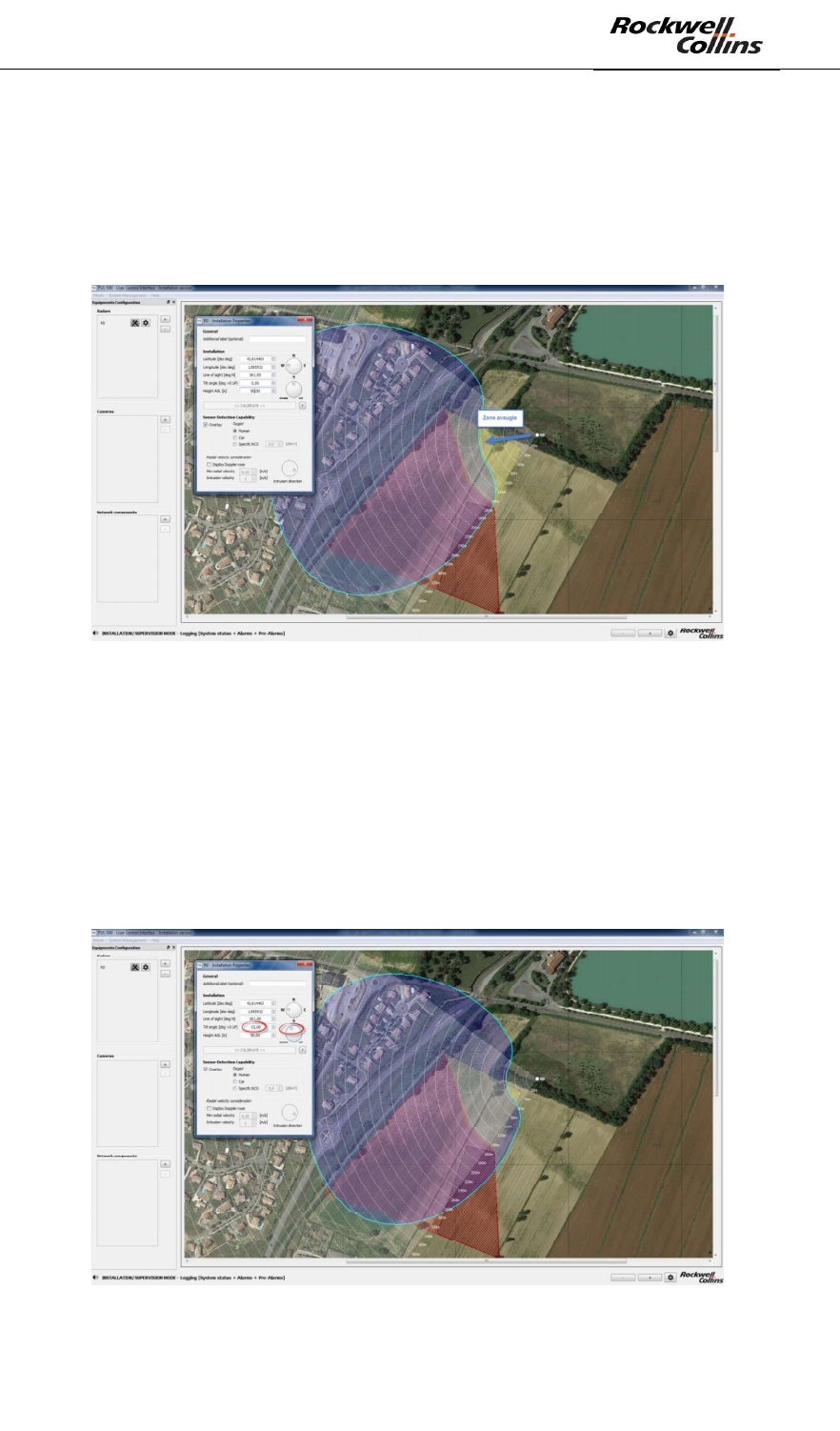
The modification of the radar height changes its coverage zone (blue pattern).
Nevertheless, the area to protect is still in the coverage zone in this example.
If trees would have been higher, the radar would have to be installed higher on the
mast and the impact on detection capability may have become significant. The
following picture presents a scenario where the radar is installed at 50m high.
Figure 62: Impact of radar position/height on detection capability
In such a configuration, the impact on the detection capability of a human intrusion
would be significant at short range. In this case, a lower tilt angle would be necessary
to recover the detection capability at short range (always keeping an eye on the long
range as the entire detection capability is impacted by a change of tilt angle).
In the case of an installation at 50m high, a tilt angle of -15° would be a good
compromise between coverage at short and long range, as shown below.
Figure 63: Modification of the tilt angle to improve detection capability
PSR-500 System Installation Guide
Page 51 / 125
CPN 222-3044-657 Rev B CAGEC F5491 Rockwell Collins - Proprietary Information
Figure 64: Closing the « Installation Properties » window
button of the radar to be configured.
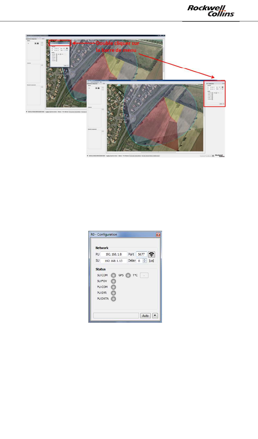
Figure 65: Opening radar configuration window
This configuration popup is actually a dockable window that will be used later on as a
way to keep an eye on the status of this radar. Indeed, if you double click on its menu
bar, it will dock into the edge of the UCI so you can keep an eye on it while doing
over things.
PSR-500 System Installation Guide
Page 52 / 125
CPN 222-3044-657 Rev B CAGEC F5491 Rockwell Collins - Proprietary Information
Figure 66 : Dockable configuration window
The network properties of the radar shall be configured (i.e: SU & PU IP addresses
and PU port). In our case: the following values are set up:
- PU IP address: 192.168.1.8
- PU Port: 5677
- SU IP address (by default) : 192.168.1.13
Figure 67: Configuration réseau SU & PU
The default IP address of the SU (192.168.1.13) may be changed, as explained in
6.2.7.
Warning: if you change this default value, the update of the PU by the PSR-500
Installer application will have to be followed by a re-start of the SU and then a re-start
of the PU.
PSR-500 System Installation Guide
Page 53 / 125
CPN 222-3044-657 Rev B CAGEC F5491 Rockwell Collins - Proprietary Information
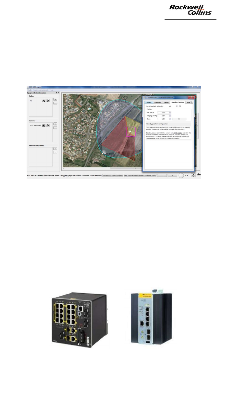
6.1.4. Step#4: Add, position and configure one or several cameras (CCS)
This paragraph is only applicable if the CSS option is included in the PSR-500
system deployed.
Once properly configured for each controlled camera, the CSS module will allow to:
- Align each camera
- Support automatic visual confirmation of intrusion alerts as precisely as
possible
In order to perform this step, the following actions shall be performed:
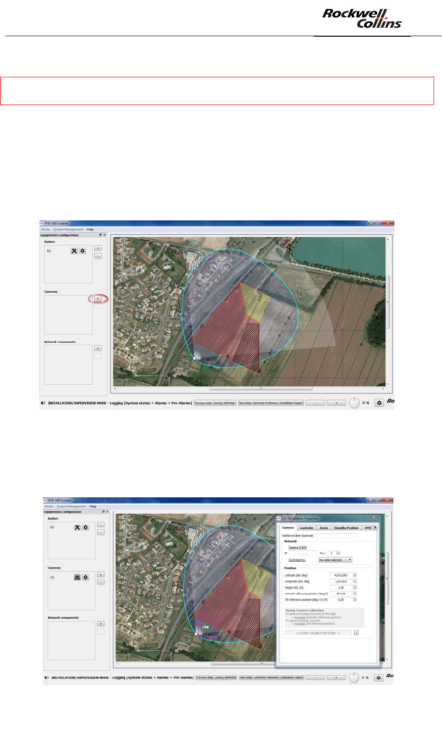
- Click on the « + » button in the camera dedicated zone (see below) to add a
camera
Figure 68: Add a camera
- Position the camera at the same location than the radar. It could be actually
positioned anywhere on the site but in our case, the camera is collocated with
the radar.
PSR-500 System Installation Guide
Page 54 / 125
CPN 222-3044-657 Rev B CAGEC F5491 Rockwell Collins - Proprietary Information
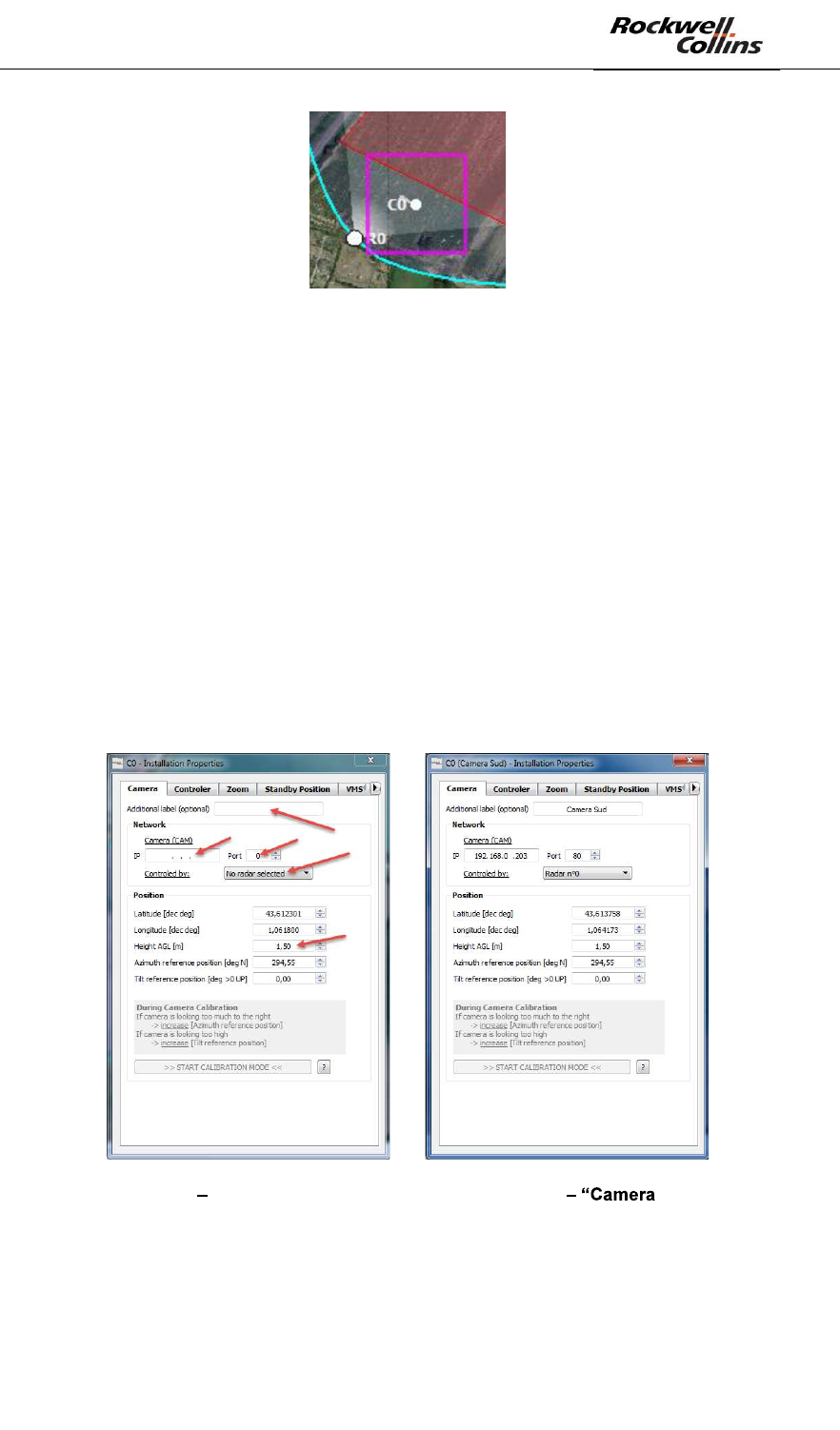
Figure 69: Set the position and the orientation of the camera
- In the Camera tab of the camera configuration window that opens
automatically, Set the following properties:
o Additional label (optional) = give a name to the camera in case of an
installation with multiple cameras
o IP = IP address of the camera
o Port = Communication port with the CCS module = 80
o Controlled by = select the radar that shall be associated to this camera
in the drop-down menu
o Latitude, Longitude = if the camera position is set manually on the
background map, these values will be update automatically, otherwise
enter them in these areas.
o Height AGL = Set the height above ground of the camera
o Azimuth reference position & Tilt reference position = these values
will be set up during the camera calibration phase, ignore them for the
moment.
o
Figure 70 Camera properties configuration window » tab
- In the Controller tab of the camera configuration window, set the following
properties related to the way the camera is controlled:
o Min zone level = minimum alerting level taken into account by the
camera
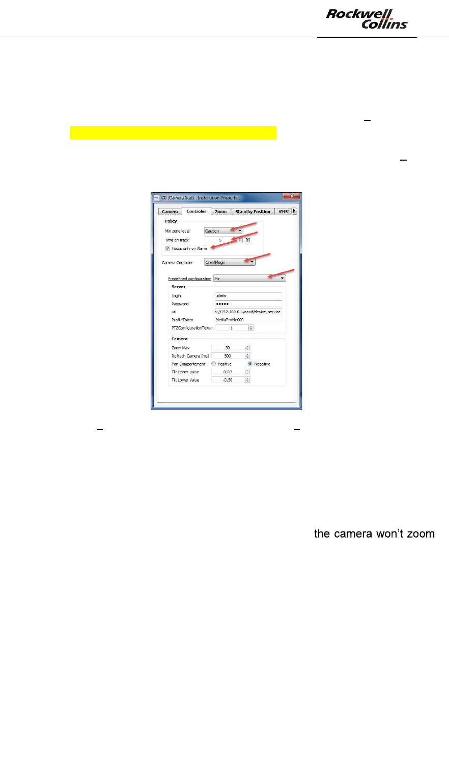
PSR-500 System Installation Guide
Page 55 / 125
CPN 222-3044-657 Rev B CAGEC F5491 Rockwell Collins - Proprietary Information
o Time on track = time spent by the camera on each alert (in case a the
radar associated with this camera raises several alert simultaneously)
o Focus only on Alarm = if selected, the camera will only be steered on
the alerts. If unselected, the camera will also be steered on the pre-
alerts (radar track not yet identified as intrusion alerts) see section
Erreur ! Source du renvoi introuvable. to enable pre-alert display.
o Camera Controller = select OnvifPlugin
o Predefined configuration = select the controlled camera brand it will
automatically fill the remaining information required in this tab.
Figure 71 Camera properties configuration window « Controller » tab
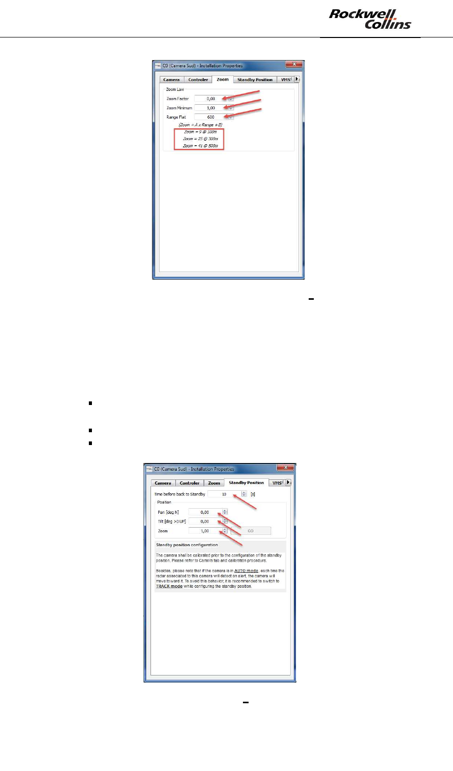
- In the Zoom tab of the camera properties configuration window, set the
following properties related to the zoom rules:
o Zoom factor = define the factor of the linear function that linked the
zoom to the distance between the alert and the camera (indications are
given in the window)
o Minimum zoom = When the alert is very closed to the camera
o Range flat = distance threshold beyond which
any more
PSR-500 System Installation Guide
Page 56 / 125
CPN 222-3044-657 Rev B CAGEC F5491 Rockwell Collins - Proprietary Information
Figure 72 - Camera properties configuration window « Zoom » tab
- In the Standby position tab of the camera properties configuration window,
set the following properties related to the standby position of the camera :
o Time before back to standby = time before the camera will get back
to its standby position in case there is no intrusion alarm anymore in the
coverage area of the radar associated with the camera
o Position
Pan = standby position pan value of the camera w.r.t. the
geographical North
Tilt = standby position tilt value of the camera w.r.t. horizontal
Zoom = standby position zoom factor of the camera
Figure 73 - Camera properties configuration window « Standby position » tab
PSR-500 System Installation Guide
Page 57 / 125
CPN 222-3044-657 Rev B CAGEC F5491 Rockwell Collins - Proprietary Information
Note: this standby position can be set at the step or once the application will be
connected to the camera which will allow the operator to see in real-time what the
camera can see in this position.
All other tabs shall be ignored.
- Close the camera « Installation Properties » window
Figure 74: Close the camera « Installation Properties » window
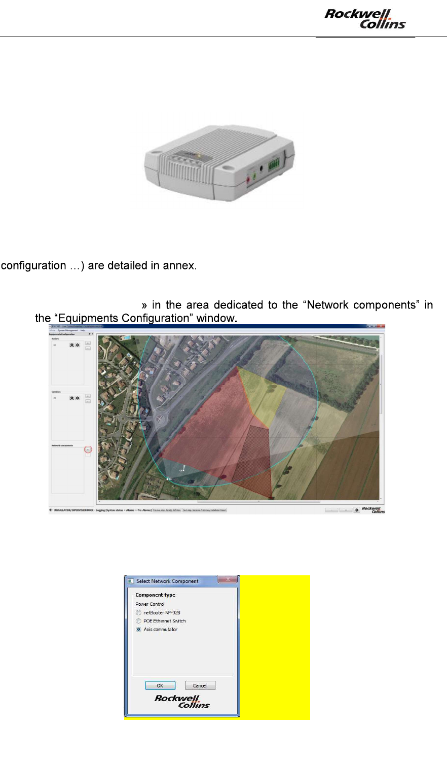
6.1.5. Step#5: add and configure network components
The network components are elements that will either add a feature to the PSR-500
system or ensure automatic maintenance of deployed radars.
The following components are the one compatible with the PSR-500 Installer:
- Switch POE = Ethernet switch allowing to remotely control the power suply of
the POE port connected to the SU. The communication protocol used is
SNMPv3. The following references are tested and compatibles:
o Switch POE CISCO IE-2000-16PTC-G-E
o Switch POE AT-IE200-6GP Allied Telesis
Figure 75 - Examples of compatible POE switch
PSR-500 System Installation Guide
Page 58 / 125
CPN 222-3044-657 Rev B CAGEC F5491 Rockwell Collins - Proprietary Information
- Dry Contact Module audio E/S AXIS P8221 = Dry Contact allowing to
remotely rebooting the PU. The communication protocol used is HTTP. The
Dry Contact module is also used to inform an external system when a zone is
in alert.
Figure 76 - Module audio E/S AXIS P8221
The deployment ways and means of these components (cabling, internal
In order to add a network component, the following actions shall be performed:
- Click the button « +
Figure 77: Add a network component
- The « Select Network Component » window opens :
A MODIFIER
PSR-500 System Installation Guide
Page 59 / 125
CPN 222-3044-657 Rev B CAGEC F5491 Rockwell Collins - Proprietary Information
Figure 78: Select Network Component window
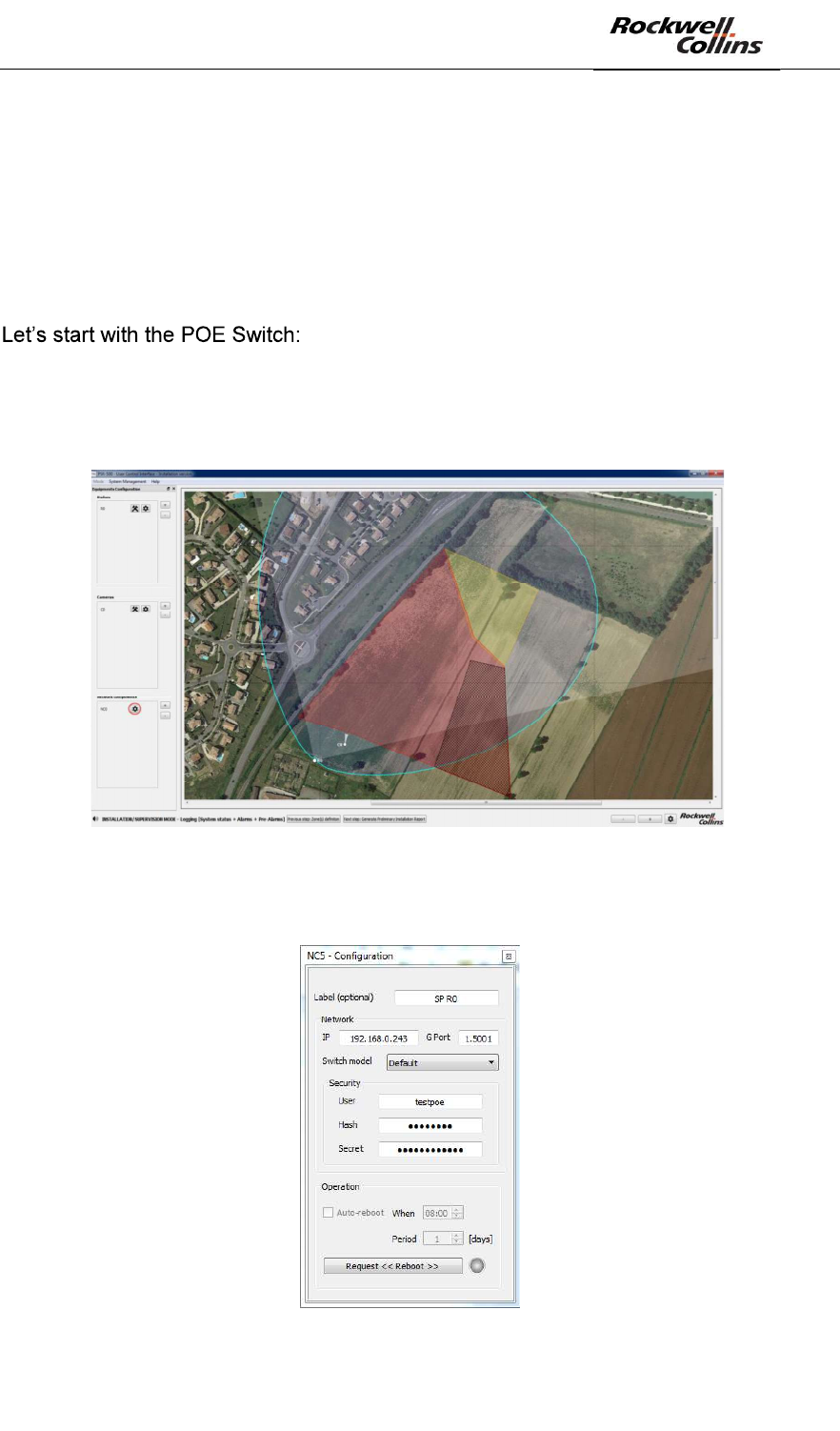
6.1.5.1. Configuration of Maintenance through POE switch and Dry Contact
Two network components are used to ensure radar maintenance:
- POE Switch to manage SU power supply
- Dry Contact to manage PU power supply
- Select the Ethernet POE switch in the network component list proposed and
click « OK »
- Click on the associated « configuration » button, as illustrated below :
Figure 79: « configuration » button associated to the network component
The following configuration window opens:
Figure 80: POE Switch configuration window
PSR-500 System Installation Guide
Page 60 / 125
CPN 222-3044-657 Rev B CAGEC F5491 Rockwell Collins - Proprietary Information
In our example, the following parameters values are set:
- Label (optional) : SP R0 for the POE Switch controlling R0
- IP : 192.168.0.243
- G Port (Group port) : 1.5001 (i.e. the port 1of the POE Switch used to power
the SU)
- Switch mode
o Default for Switch POE AT-IE200-6GP Allied Telesis
o Cisco for Switch POE CISCO IE-2000-16PTC-G-E
- User, Hash and Secret shall be configured based on POE Switch
configuration credentials.
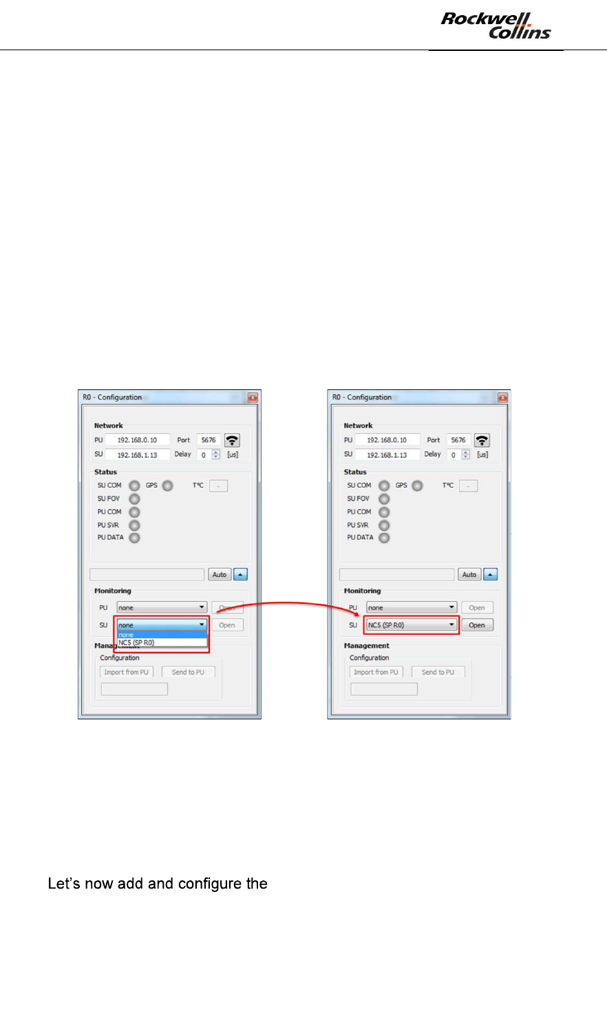
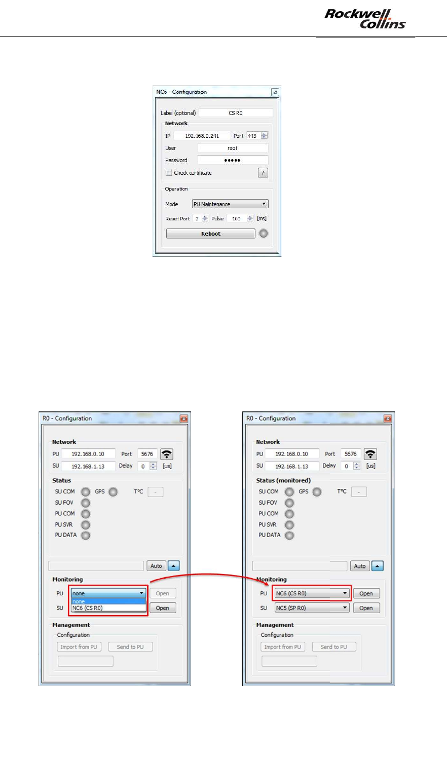
Association between the POE Switch and the radar (more precisely its SU) is done in
the radar configuration pop-up when extended. In our example, the automatique
maintenance of the SU (radar R0) will be done by the POE Switch we have created
(only POE Switchs are displayed in the combo box for the monitoring of the SU).
Figure 81: Selection of the POE switch for the automatic maintenance of the SU
When the POE Switch has been associated to the radar, the « OPEN » button is
enabled, in order we can directly open the associated network component. A manual
test can be performed by clicking « Request Reboot » button. The associated SU
shall restart.
- Close the POE Switch configuration window
- Dry Contact
- Add a new network component
- Select the Axis commutator component in the proposed network component
list and click « OK »
- Open the Dry Contact configuration window
PSR-500 System Installation Guide
Page 61 / 125
CPN 222-3044-657 Rev B CAGEC F5491 Rockwell Collins - Proprietary Information
The configuration window opens:
Figure 82: Dry Contact Configuration window
In our example, the following parameter values are set:
- Label (optional): CS R0 for the Dry Contact that controls R0
- IP : 192.168.0.241
- Port : 443
- User, password and Reset port shall be configured in conformity with Dry
Contact credential configuration
- For an automatic maintenance of the PU, the mode is selected to « PU
Maintenance » and the pulse duration is 100ms by default.
Figure 83: Select the Dry Contact for the automatic maintenance of the PU
PSR-500 System Installation Guide
Page 62 / 125
CPN 222-3044-657 Rev B CAGEC F5491 Rockwell Collins - Proprietary Information
When a Dry Contact has been associated to the radar, the « Open » button is
enabled, in order we can directly open the associated network component. A manual
test can be performed by clicking « Reboot ». The associated PU shall restart.
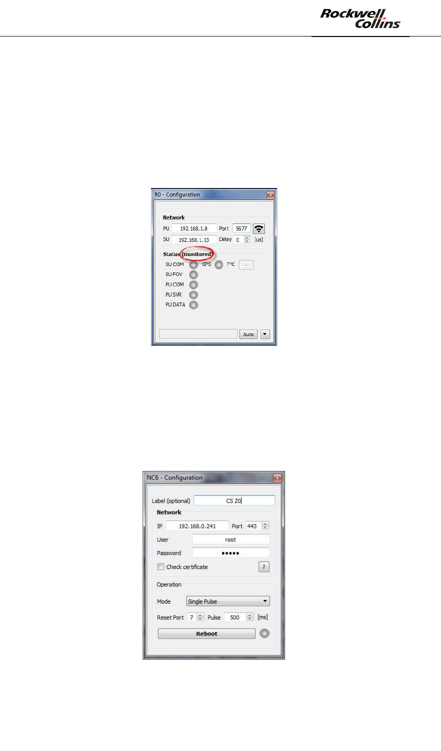
If these components are configured as previously explained and associated to the
radar, then when a failure will be detected on the SU or the PU, than an automatic
reboot will be performed. This monitoring activation is indicated by the « monitored »
label that appears next to « Status » in the radar Configuration window when a
network component is associated to the radar.
Figure 84: Radar monitored and under automatic maintenance
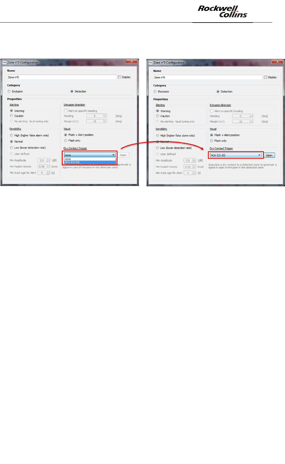
6.1.5.2. Dry Contact trigerring on zone in alarm
The Dry Contact module can also be associated to a surveillance zone to inform an
external system when a zone is in alarm. The component will then be configured in
« Single Pulse » mode, taking care to use a free Reset Port and adapting the pulse
duration to the external system interface.
Figure 85: Dry Contact in « Single Pulse » mode configuration window
Association with the surveillance zone is done in the surveillance zone configuration
window. In our example, the CS Z0 Dry Contact will be triggered when the
PSR-500 System Installation Guide
Page 63 / 125
CPN 222-3044-657 Rev B CAGEC F5491 Rockwell Collins - Proprietary Information
surveillance zone Z0 will be in alarm (only Dry Contacts configured in « Single
Pulse » mode will appear in the combo box).
Figure 86: Dry Contact Selection for zone alerting
When a Dry Contact has been associated to the zone, the « Open » button is
enabled, in order to be able to directly open the associated network component. A
manual test can be done, clicking on the « Trigger » button. The Rest Port of the dry
contact associated to the zone will be triggered for the specified duration.
When an alert will be detected in the zone associated to a dry contact, this one will
be triggered only for the specified duration. While an alert is present in the zone (the
zone is in alarm), no new trigger will occur on new alert. We must wait the zone is no
more in alarm before a new alert trigger the dry contact again. If an alert is detected
in a position covered by 2 surveillance zones associated to different dry contacts, the
2 dry contacts will be triggered.
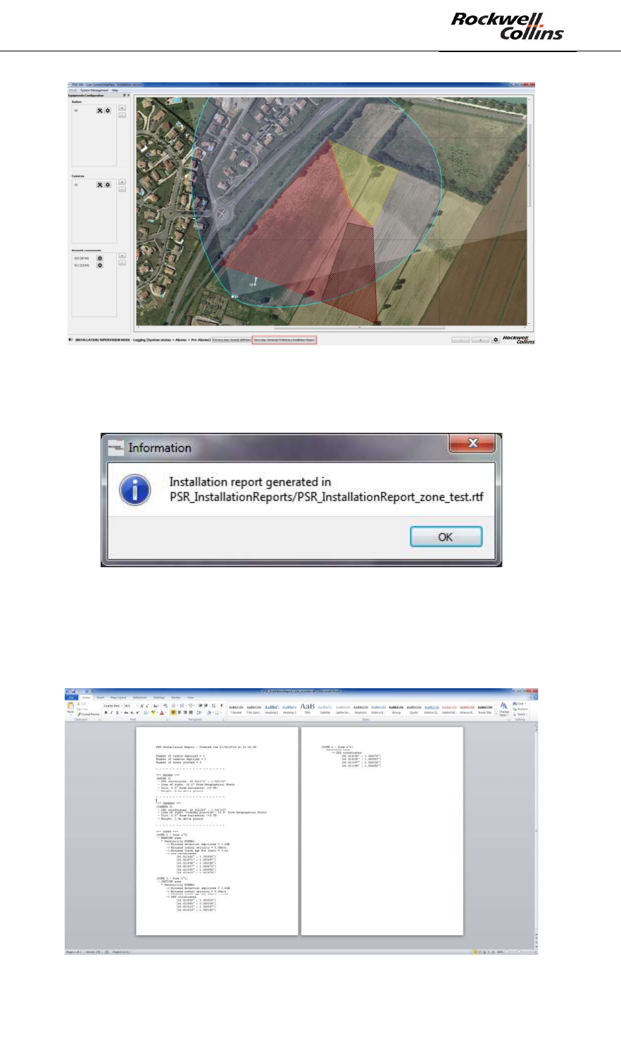
6.1.6. Step#6: Generate the preliminary installation report
The following actions shall be performed :
- Click on « Next step : Generate Preliminary Installation Report » button
PSR-500 System Installation Guide
Page 64 / 125
CPN 222-3044-657 Rev B CAGEC F5491 Rockwell Collins - Proprietary Information
Figure 87: Button to generate the preliminary installation report
- The following window opens when the report is correctly generated
Figure 88: Preliminary Installation report is correctly generated
- The report may be opened from the following address « < PSR-
500_Installer_Directory>\PSR_InstallationReports\ » with a text editor and can be
print to help the installation support team during the installation and the
deployment of the system on site.
Figure 89: Preliminary installation report
PSR-500 System Installation Guide
Page 65 / 125
CPN 222-3044-657 Rev B CAGEC F5491 Rockwell Collins - Proprietary Information
- Click on the following window opens automatically :
Figure 90: End of installation window
- At the step, 2 options are possible:
o If you are deploying the radar system at the same place as you prepare
the previous preparation of the system configuration, the PSR-500
Installer can stay opened. Once the physical deployment of the system
is done, click on « Yes » to pass to next step.
o If you are not deploying the radar at the same place where you perform
the system configuration preparation, the PSR-500 Installer shall be to
go on the deployment site. Click on « No » to interrupt the installation
wizard and close the PSR-500 Installer (click the cross in the tope
right-hand corner). Click « Yes » to save :
Figure 91: Close the PSR-500 Installer and save the system configuration
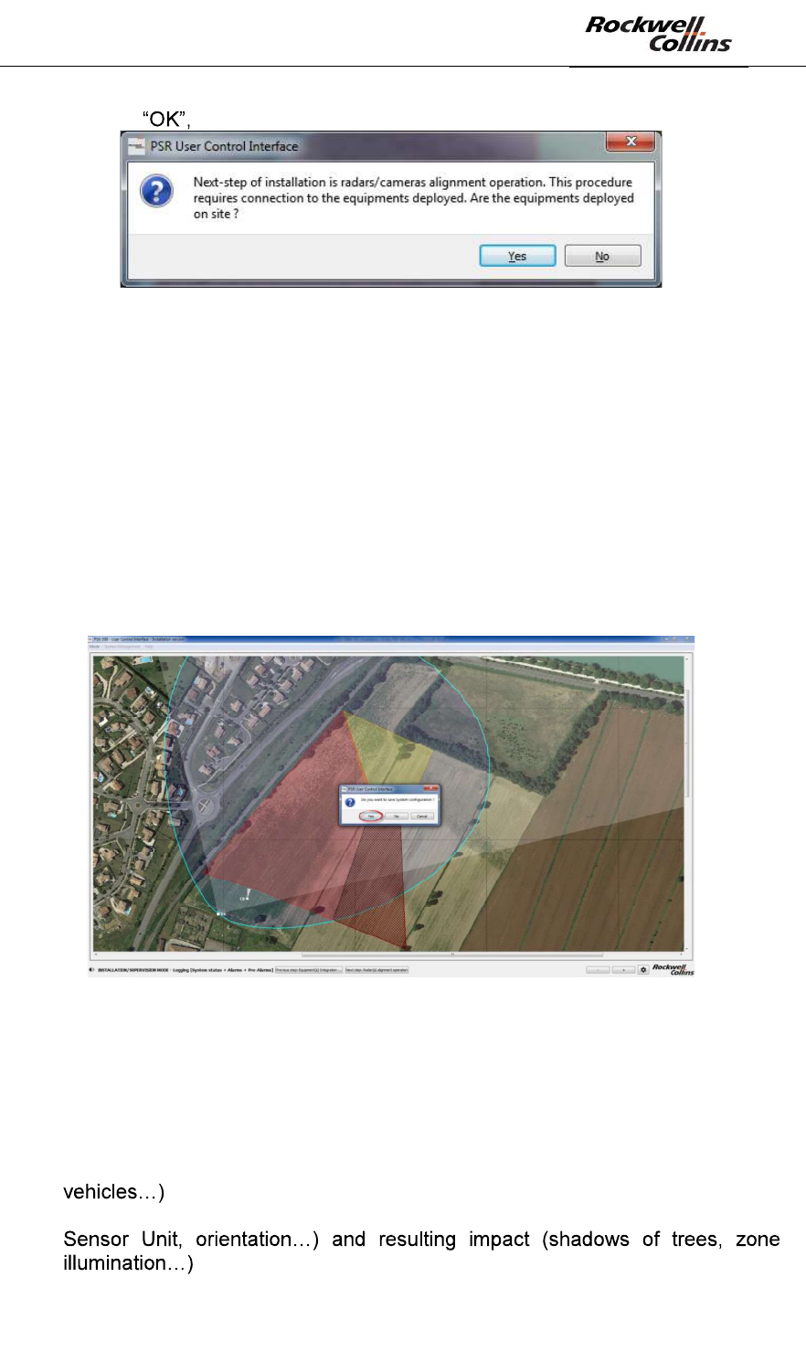
6.1.7. Step#7: Visit the site and Validate/Update the foreseen installation
Once on the site, and based on the preliminary installation report, the attention shall
be focused on the following « O-IC-S » points:
- O = Obstacles between the radar location and potential intrusions you did not
expected based on the background map analysis (buildings, vegetation,
- IC = Installation constraints on the mast (height above ground of the PSR
PSR-500 System Installation Guide
Page 66 / 125
CPN 222-3044-657 Rev B CAGEC F5491 Rockwell Collins - Proprietary Information
- S = Spurious activity on the area covered by the Sensor Unit (vehicles traffic,
air conditioner, windmills, WiFi transmitter at the same
o Traffic of vehicles = traffic of vehicles in the coverage area of the
radar may cause false alarms if the operator have not create exclusion
zone. Moreover, if the traffic is dense, this area will desensitize the
radar for any intrusion occurring on similar range and radial velocities
than cars (see complete explanation below). It is recommended to turn
the radar away from any busy road.
o Air conditioning blocks, windmills = any object that includes a
rotating piece in the radar coverage area may cause false alarms if this
object is not in an exclusion zone. . It is recommended to direction the
radar so that any rotating object in the direct proximity is at the back of
the radar as much as possible.
o Transmitter at the same frequency band as the PSR-500 (example:
WiFi transmitter in the same frequency band as the PSR-500); it is
recommended to direction the radar so that the disturber is at his back
as much as possible.
o Building proximity = the proximity of building is not an issue as long
as the radar is not oriented toward it. In case such a situation may
happen, the radar may be disturbed by its own emission that is
reflected by the wall of the building. This will cause a desensitization of
the radar and thus a degradation of the detection performances. It is
therefore recommended to avoid the combination of proximity with a
building and the illumination of the building.
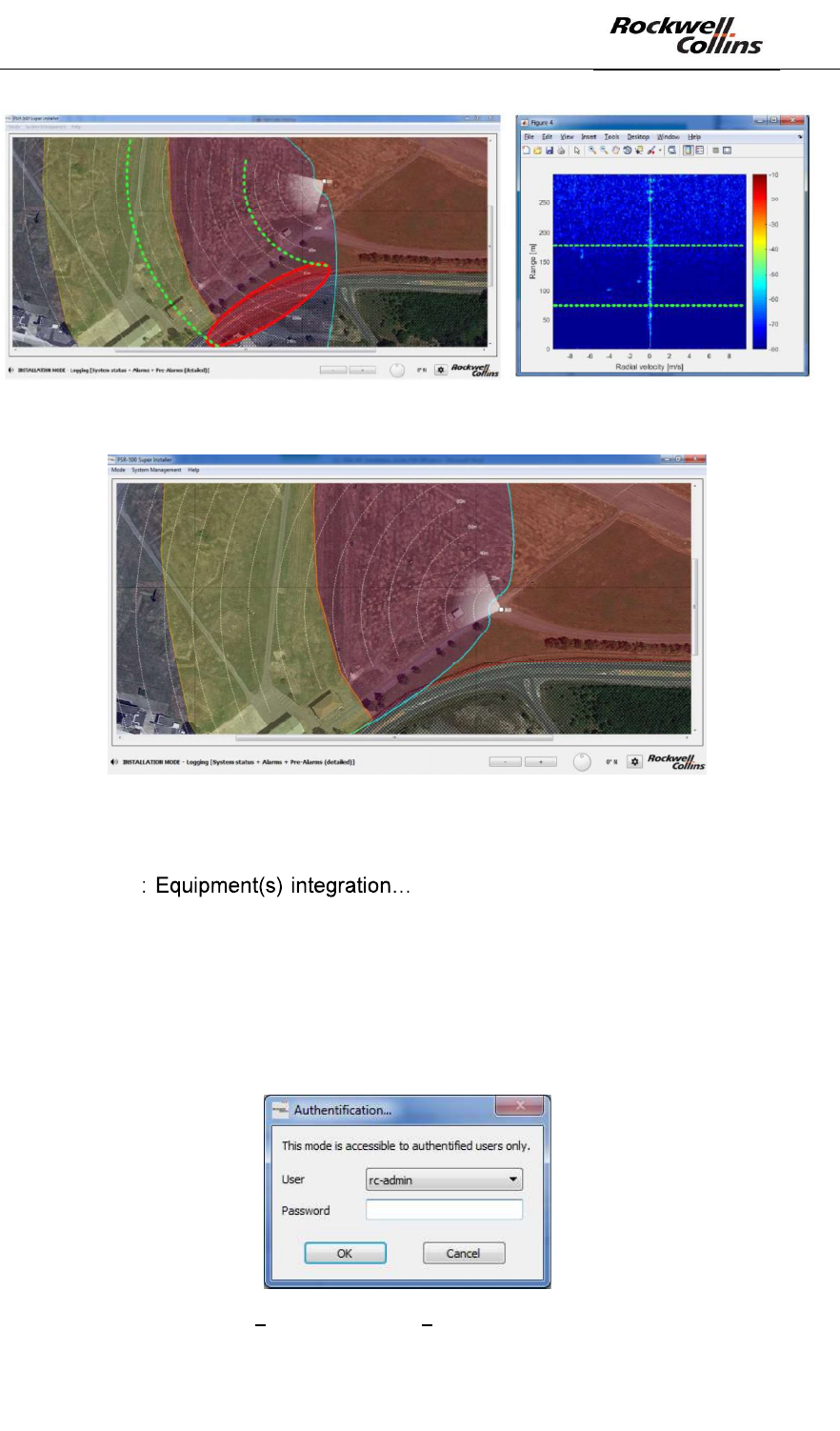
Busy road effect
PSR-500 radars map the backscaterred energy in range and radial velocity over their
complete coverage (~90° in azimuth) before trying to detect intrusions.
Every target over their coverage and moving at range and radial velocity similar to
the one expected for human intrusions may potentially mask human intrusions.
- It is important to create exclusion zones on these areas to avoid false alarm
on such areas considered as public and authorized areas
- Nevertheless, exclusion zones will not avoid the fact that some cars may mask
human intrusions if they move at similar range and radial velocity than the
human intrusion. The radar is therefore desensitized for human detection. The
busier the road the higher the risk.
In order to illustrate this effect, the left picture below shows a deployment performed
close to a busy road. Although the traffic (red area) is not geographicaly in the area
of interest for the surveillance (field), the cars move at a range and a radial velocity
close to the one expected for human intrusions over the area of interest (as we can
see of the right picture which is the range x radial velocity map the radar is working
on). The road is in a exclusion zone, avoiding false alarm on cars. But cars radar
signature will regularly mask human intrusion radar signatures that may occur on the
entire coverage bounded with green lines.
PSR-500 System Installation Guide
Page 67 / 125
CPN 222-3044-657 Rev B CAGEC F5491 Rockwell Collins - Proprietary Information
In this case, it is recommended to turn the radar to less illuminate the busy road.
To update the installation properties, follow the actions listed below:
- If the PSR-500 Installer application is not closed, click on the « Previous
steps » » buttons on the bottom left-hand corner
to get back to the configuration phase, and then set up the properties of the
equipment and generate the preliminary installation report to finally reach the
calibration phase (cf §0).
- If the PSR-500 Installer application is closed and the configuration saved,
follow the steps below :
o Start the PSR-500 Installer application
o The authentification window opens
Figure 92 PSR-500 Installer Authentification window
PSR-500 System Installation Guide
Page 68 / 125
CPN 222-3044-657 Rev B CAGEC F5491 Rockwell Collins - Proprietary Information
o Enter the default password
o Click on « » :
Figure 93: PSR-500 Installer « » button
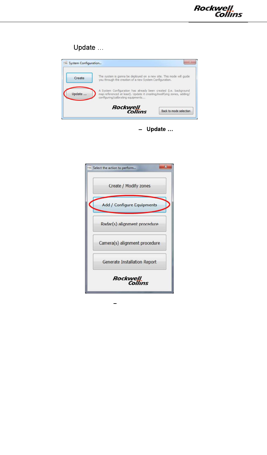
o Select the system configuration previously saved
o Click on « Add / Configure Equipments » button:
Figure 94: PSR-500 Installer « Add / Configure Equipments » button
The following window automatically opens :
PSR-500 System Installation Guide
Page 69 / 125
CPN 222-3044-657 Rev B CAGEC F5491 Rockwell Collins - Proprietary Information
Figure 95: PSR-500 Installer open the saved system configuration
o Update the installation properties of the equipments
o Click on mune bar « System Management -> System -
> Generate Installation Report » to generate the installation report :
Figure 96: PSR-500 Installer Generate installation report from the menu bar
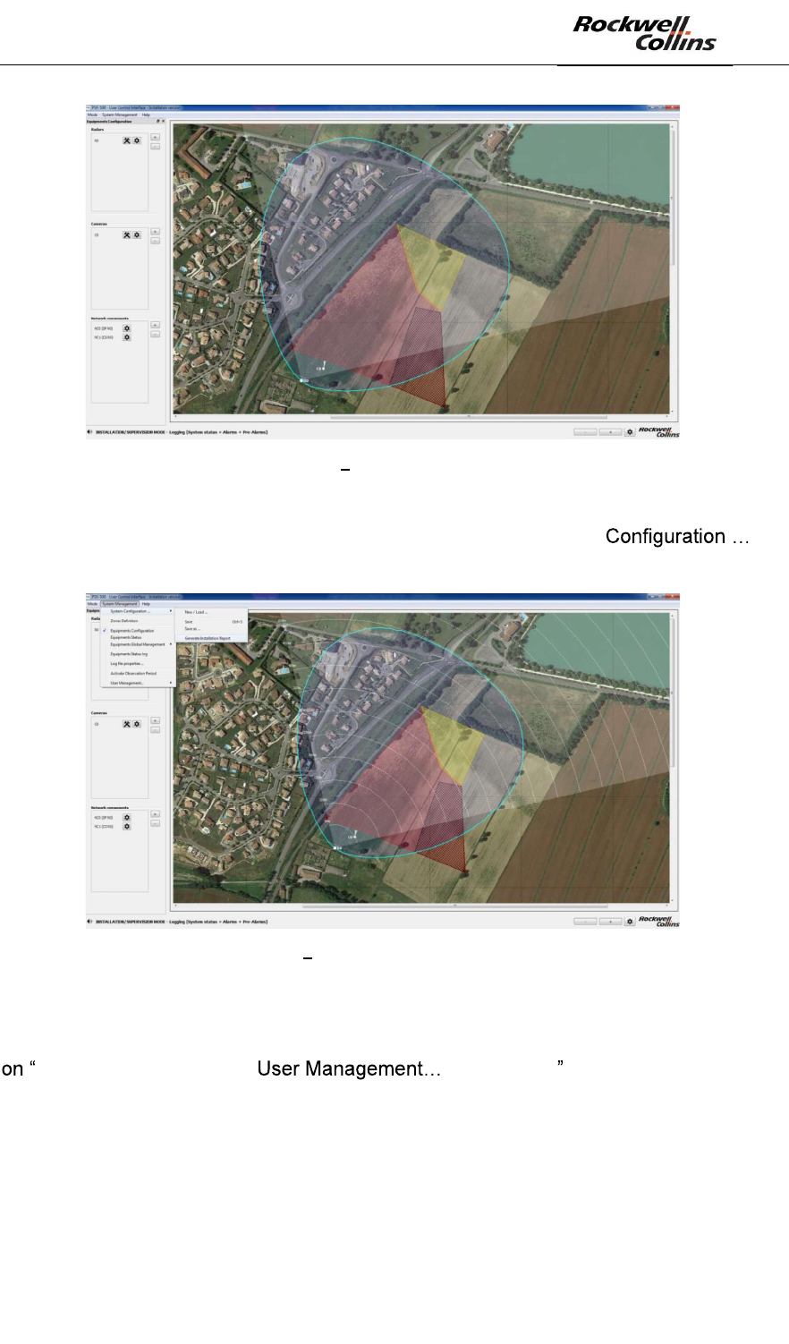
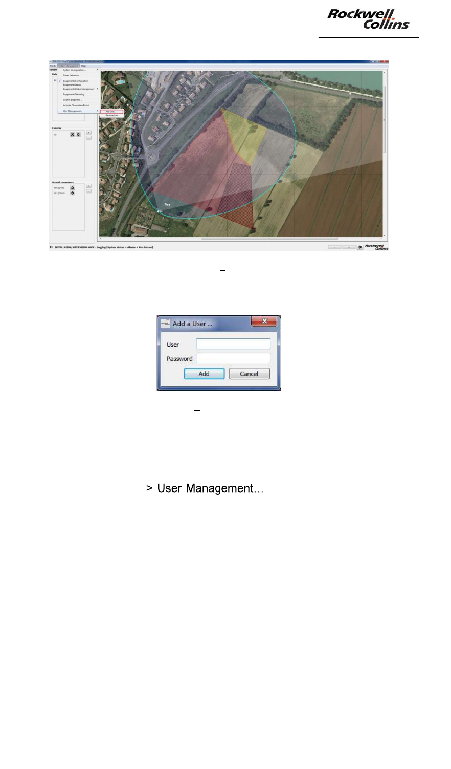
6.1.8. Step#8: Add installation operators
To add installation operators, once the PSR-500 Installer application opened, click
System Management -> -> Add User .
PSR-500 System Installation Guide
Page 70 / 125
CPN 222-3044-657 Rev B CAGEC F5491 Rockwell Collins - Proprietary Information
Figure 97: PSR-500 Installer Add installation operators
- The following window opens. Create a new user by entering a user name and
a password.
Figure 98: PSR-500 Installer installation operator creation window
These installation operators will now appear in the list of authorized operators when
the application starts.
To delete installation operators, once the PSR-500 Installer application opened, click
on « System Management - -> Remove User » and select in
the list the name of the user to be deleted.
The names and the passwords are locally stored within the PSR-500 Installer
directory in an SQL database. Only hashed passwords are stored.
PSR-500 System Installation Guide
Page 71 / 125
CPN 222-3044-657 Rev B CAGEC F5491 Rockwell Collins - Proprietary Information
6.2. Installation & start of a radar
As a reminder, a radar of the PSR-500 system is composed of a SU and a PU. This
part will describe how to physically install this set and start it up.
In case of a deployment with several radars, the operator shall also configure the
interoperability of each radar in order to exploit them (as explained in the next
section).
6.2.1. Cabling
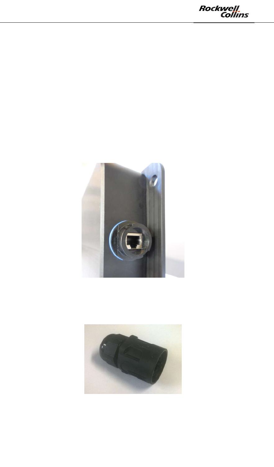
The SU is powered and communicate through the Ethernet. The Ethernet plug of the
radar is defned as follow:
- Connector RJF RB 71 (Amphenol)
- Ethernet Plug RJF RB 6 (Amphenol)
- Cat IP67
Figure 99: PSR-500 SU plug
The Ethernet cable connected to the SU shall be Cat.6 S/FTP.
Its end connected to the SU shall be equipped with a RJF RB6 adapter as illustrated
by the following picture:
Figure 100: Ethernet Connector RJF RB 6
6.2.2. Dimensions
- Length : 370 mm
- Width : 144 mm
PSR-500 System Installation Guide
Page 72 / 125
CPN 222-3044-657 Rev B CAGEC F5491 Rockwell Collins - Proprietary Information
- Depth : 50 mm
- Fixings : 348.5 * 106 mm ; holes diameter = 8 mm
- Weight : 1.5kg
6.2.3. Power Supply
The SU shall be power supplied with a 48V POE (Power Over Ethernet). It does not
require any additional specific cabling. The 48V POE shall be compliant with
802.3af/at standard and shall be configured in half-duplex.
6.2.4. Energy Consumption
The energy consumption of the SU is 8W.
6.2.5. Direction of installation
The radar of the PSR-500 system shall be installed as recommended below.
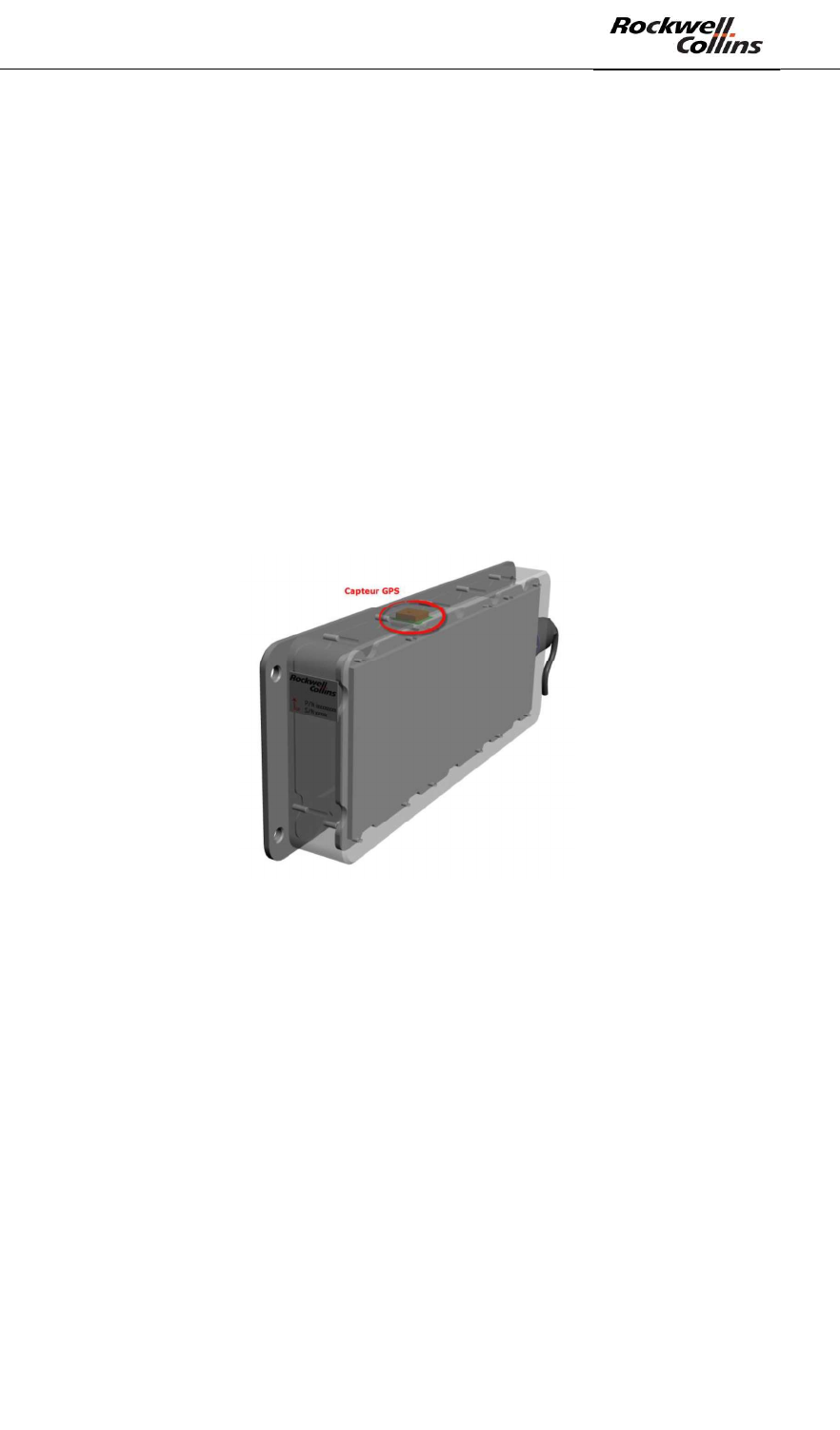
Recommendation 1 = the SU includes a GPS antenna used to receive the GPS
signal. This signal is used to synchronize the different SU together and ensure their
interoperability.
Figure 101: Position of the GPS antenna on the PSR-500 radar
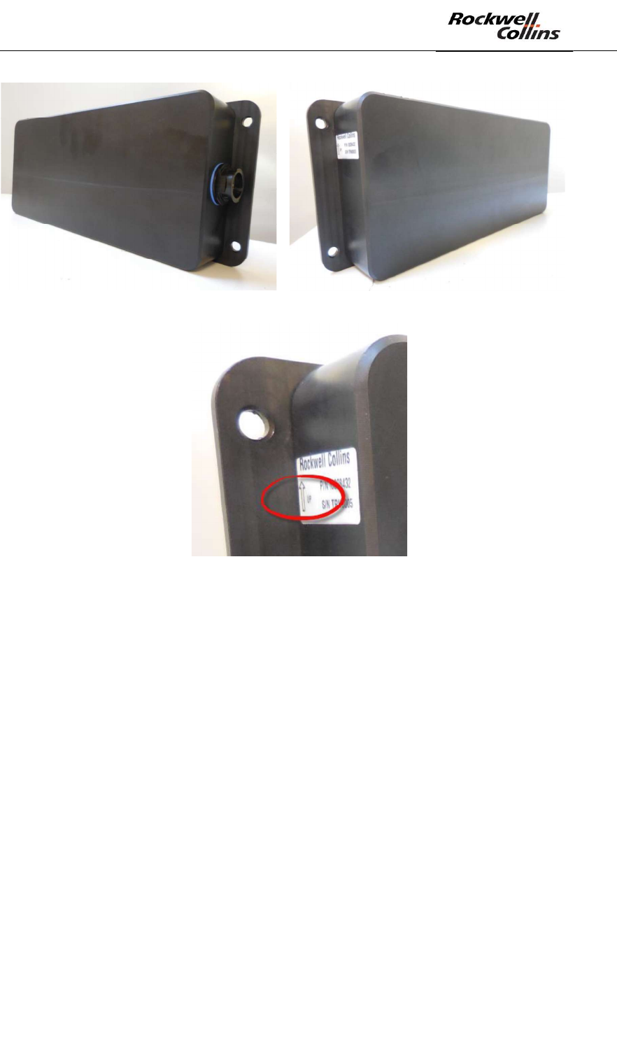
The direction of installation is thus identifiable thourgh two points of reference:
- On the edge of the radar, an arrow/text is present. This arrow/text shall be
direction toward the up when the radar is installed.
- when the operator is in front of the radar, the RJ45 connector shall be on the
right of the radar.
PSR-500 System Installation Guide
Page 73 / 125
CPN 222-3044-657 Rev B CAGEC F5491 Rockwell Collins - Proprietary Information
Figure 102: Radar of the PSR-500 correctly oriented
Figure 103: Arrow/text on the edge of the radar
Recommendation 2 = le top of the radar shall be cleared of any obstacles in order
that the GPS antenna correctly received the GPS signal.
Recommendation 3 = the close proximity of the radar (<1m) and the radar beam
area shall be cleared of obstacles as much as possible.
Recommendation 4 = each radar of the PSR-500 system shall be oriented and tilted
following the conclusion of the preparation phase of the deployment. The following
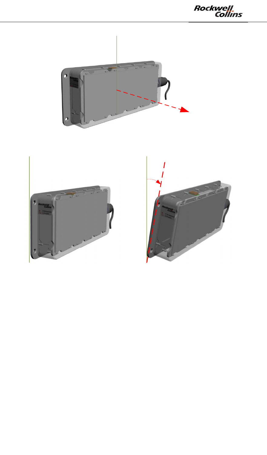
figures illustrate the radar points of reference.
PSR-500 System Installation Guide
Page 74 / 125
CPN 222-3044-657 Rev B CAGEC F5491 Rockwell Collins - Proprietary Information
Axe de visée
du radar
Figure 104: line of sight of the PSR-500 radar
Inclinaison
du radar < 0
Inclinaison du
radar nulle
Figure 105: Tilt indications for the PSR-500 radar
Note: when the radar is installed below 6m height, it is recommended to keep a zero
Tilt to keep good detection performance at 500m.
6.2.6. Network configuration
The SU integrated a DHCP client in order to retreive its IP address from the network.
- When the SU is powered up, the DHCP client is started and the SU waits for
an IP address. Any IP address can be allocated to the SU.
- After 30 seconds, if no IP address is allocated to the SU, it uses its default IP
address i.e.192.168.1.13
In order to be integrated in a DHCP server, the MAC address of the SU can be
retrieved on the stickers on the edge of the SU.
PSR-500 System Installation Guide
Page 75 / 125
CPN 222-3044-657 Rev B CAGEC F5491 Rockwell Collins - Proprietary Information
6.2.7. SU to PU connection
The POE connection of the SU to the PU is at the choice of the installation operator.
The installation operator shall define the network configuration so that the PU and the
SU can communicate, given the IP address allocated to the SU.
The current delivered disk image of the PU is configured to be connected with an SU
configured with its default address, i.e. 192.168.1.13. If the user allocates a different
IP address to the SU through a DHCP server, then the PU will be updated when it
will connect to the PSR-500 installer for the first time.
Warning: if the default IP address is modified, the PU update by the PSR-500
installer shall be followed by a reboot of the SU and then a reboot of the PU.
6.2.8. Radar Power Up
If the PU has been installed in compliance with the installation procedure 226-0098-
036_Installation_Logiciels_Activation, then at the power up of the PU the Tracking
software automatically starts, configuring the emission of the SU. The SU starts its
emissions and the radar is started. The following steps can be performed.
6.2.9. Update of each PU
We shall now connect the PSR-500 installer to each PU in order to apply the system
configuration previously prepared. The following procedure shall be performed for
each radar.
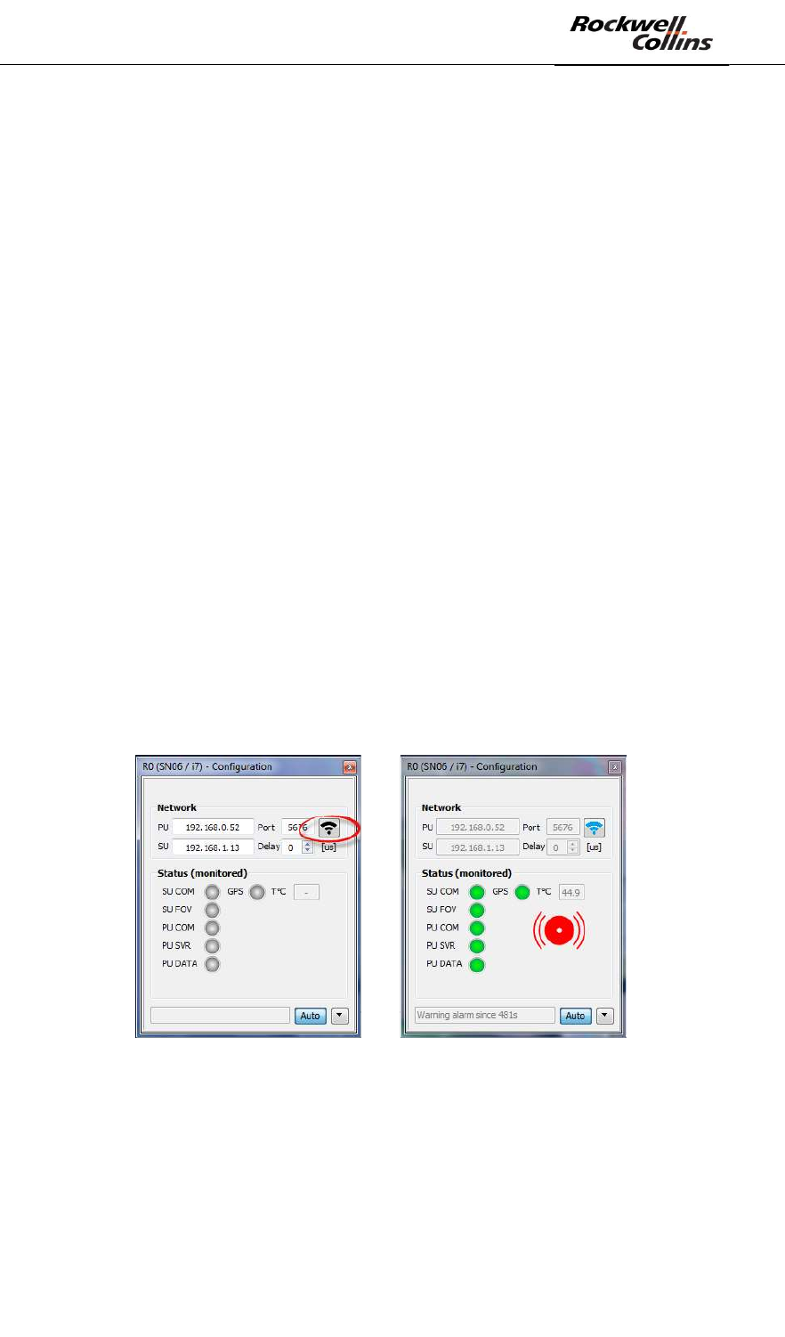
- Open the configuration window of the radar to be updated.
- Click on the button to connect to the associated PU :
Figure 106: Connection to the PU of a radar
- All the lights shall turn green. If this is not the case, confer to the debug
section in annex of this document.
- Since it is the first time that the installation operator connect to the PU (that
only have a blank system configuration), the PSR-500 Installer application
automatically detect that the PU shall be updated.
- The following window automatically opens.
PSR-500 System Installation Guide
Page 76 / 125
CPN 222-3044-657 Rev B CAGEC F5491 Rockwell Collins - Proprietary Information
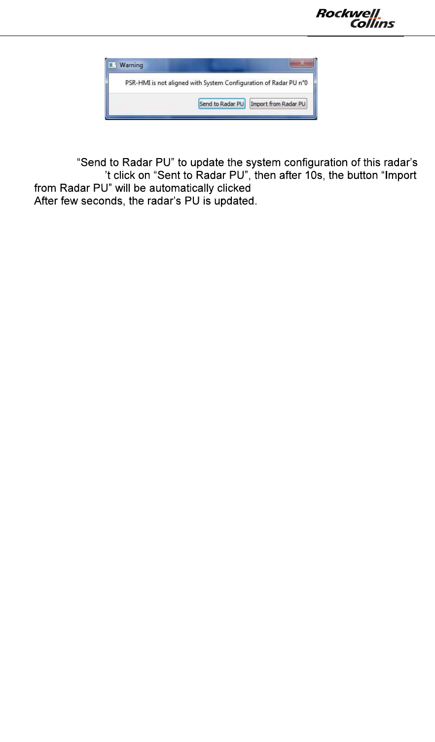
Figure 107: System configuration alignment window
- Click on
PU. If you don
-
Re-do the same procedure for all the deployed radars.
Now that the system configurations of all the radars are up to date, we can now pass
to the configuration of the interoperability of the radars.
PSR-500 System Installation Guide
Page 77 / 125
CPN 222-3044-657 Rev B CAGEC F5491 Rockwell Collins - Proprietary Information
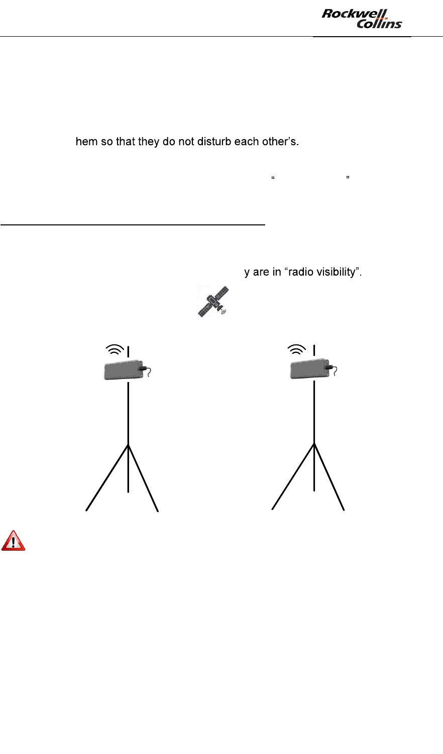
6.3. Interoperability of the radars
Before being able to the do the alignment and the deployment validation of each
radar, we shall first configure the interoperability of the radars.
Indeed, if several radars shall be installed on the same site, it is essential to position
and configure t
- Positionning = ensure a minimum physical isolation (see below)
- Configuration = in case the radar are in radio visibility , configure the
synchronization of their emission (see below definition)
Note on the capability of « inter-SU synchronization»
The SU of the PSR-500 system includes a GPS antenna in order to synchronize the
FMCW emissions of each SU on a GPS clock. This synchronization is essential to
avoid interferences between the SUs in case the
Figure 108: Synchronization of the emissions of the SU thanks to the GPS signal
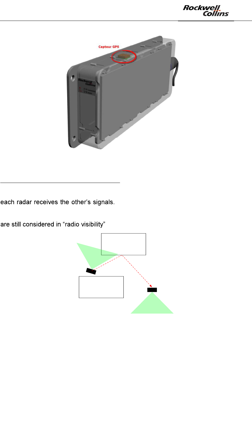
Note: the GPS antenna of the SU is located at the top of it, it is therefore
essential that the top of each SU remains clear if any obstacles with a direct view to
the sky.
PSR-500 System Installation Guide
Page 78 / 125
CPN 222-3044-657 Rev B CAGEC F5491 Rockwell Collins - Proprietary Information
Figure 109: GPS antenna position on the PSR-500 radar
Note on the concept of « radio visibility »
If two SU emits in a free space, there are in « radio visibility » of each other since
If two SU are isolated because of obstacles
in the visible domain, the emission of an SU may still be received with enough power
by the other due to reflections on several obstacles. In such conditions, the two SU
.
Bâtiment
Bâtiment
SU1
SU2
Les SU ne sont pas en
visibilité « visible
» mais
sont en visibilité
« radio »
Figure 110: Example of jamming of the SU1 by the SU2 due to the buildings
In such a configuration, the emissions of the two radars shall be synchronized. A time
offset w.r.t. to the GPS clock of reference will be added to each radar emission. The
offset will be different for each radar.
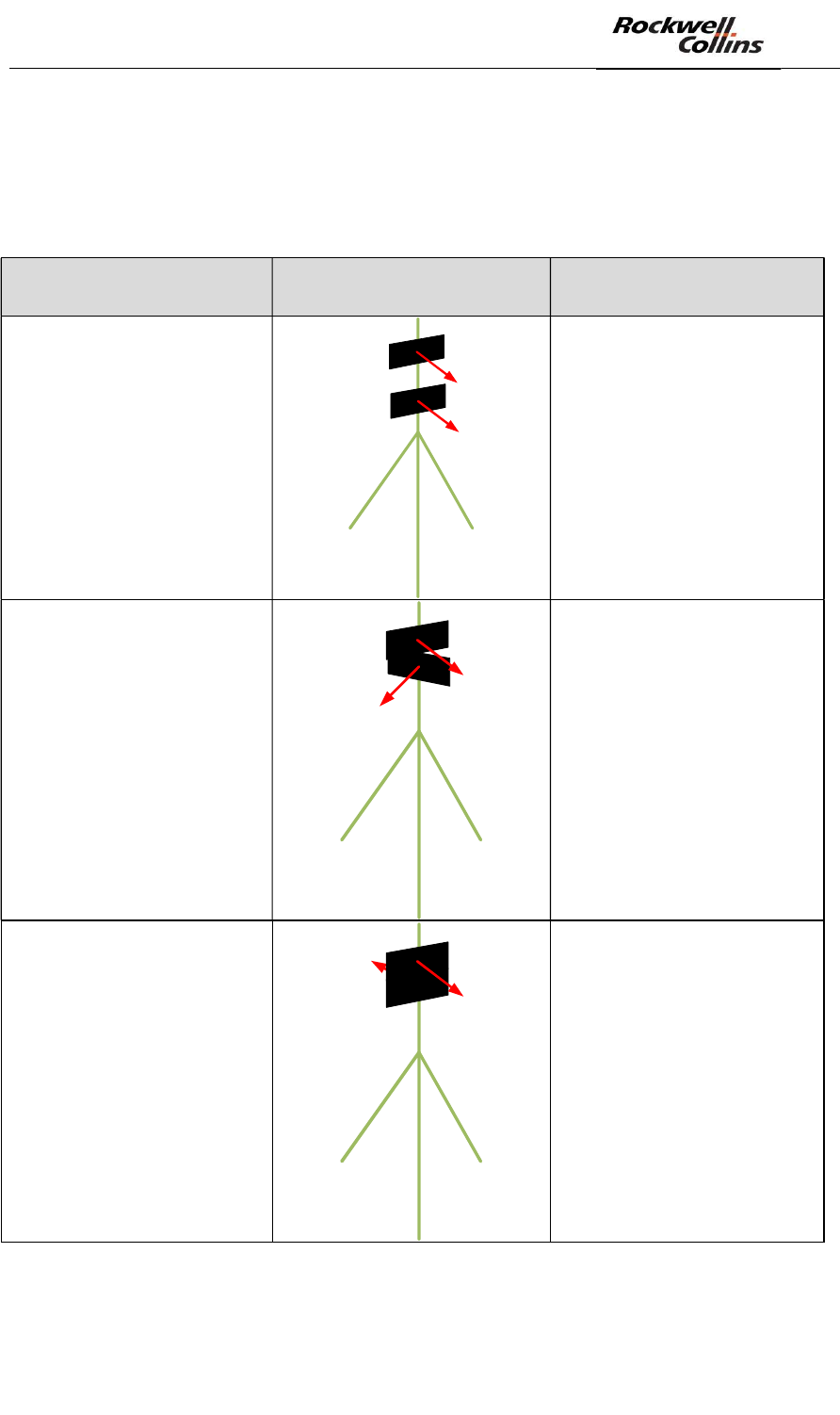
6.3.1. Relative positioning
First of all, we must ensure that the physical isolation between two SU is enough:
- Vertical distance
- Horizontal distance
- Respective lines of sight
PSR-500 System Installation Guide
Page 79 / 125
CPN 222-3044-657 Rev B CAGEC F5491 Rockwell Collins - Proprietary Information
If the minimum physical isolation is not respected, the radar will disturb each other
whatever their synchronization properties.
The following abacuses indicate the minimum physical isolation to be applied for
some typical installations:
Installation scheme Distance
Same mast
Same line of sight
Minimum of 2m
Same mast
90° between the two lines
of sight
Minimum of 70cm
Same mast
180° between the two
lines of sight
Minimum of 70cm
PSR-500 System Installation Guide
Page 80 / 125
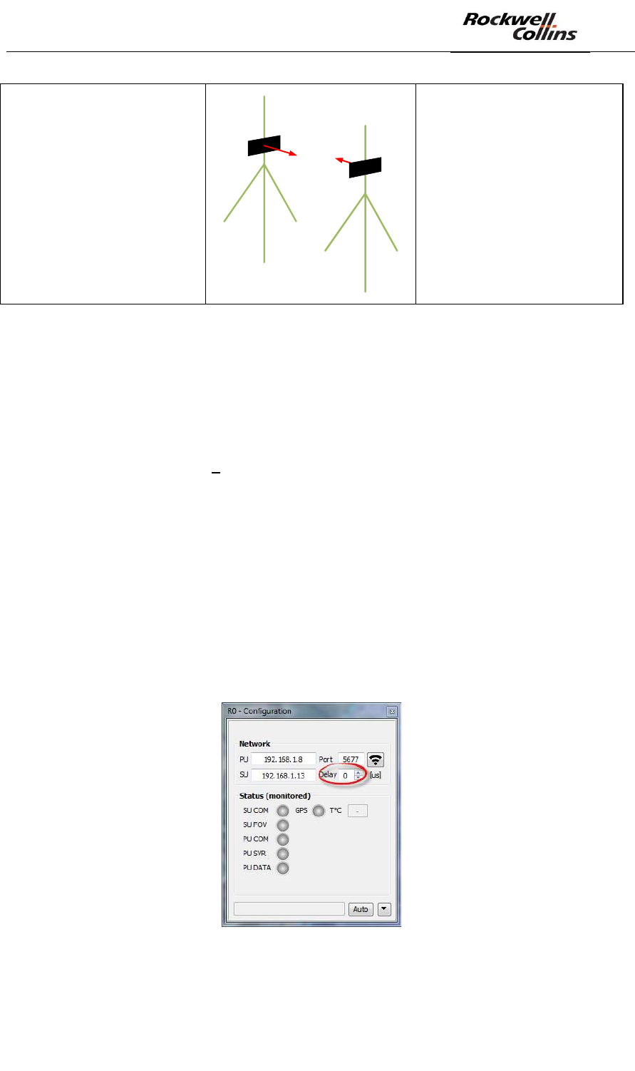
CPN 222-3044-657 Rev B CAGEC F5491 Rockwell Collins - Proprietary Information
Different mast
180° between the two
lines of sight
Minimum of 20 m
Figure 111: Abacuses of minimum physical isolation
Once that physical isolation is respected, we can now proceed with the configuration
of radar interoperability. As indicated above, this synchronization is required if
several SU are in « radio visibility ».
6.3.2. Radio environment analysis
We must first check that there is no jammer in the PSR-500 system radar frequency
band of operation [5.77GHZ 5.87GHz].
To do so, we are going to use one of the deployed radar as « spectrum analyser ».
First, we are going to set the synchronization of this radar to be sure that it does not
« see » any other radar of the deployed PSR-500 system and that the cleanliness of
its signal is representative of the radio environment.
To set the synchronization of the PSR-500 system radar, we shall tune the offset of
the start time of the FMCW waveform w.r.t. the GPS clock. This time offset is called
« delay » and is set in microseconds.
This « delay » can modified through the radar network property configuration window.
Figure 112: setting of a radar delay
By default, all radars are synchronized on 0us.