Rockwell Collins 6229210 TRANSPONDER User Manual P4
Rockwell Collins Inc TRANSPONDER P4
Contents
User Manual P4

ROCKWELL COLLINS
COMPONENT MAINTENANCE MANUAL with IPL
TDR-94, PART NO 622-9352
MAINTENANCE AID/SCHEMATIC CHANGES
REVISION
IDENT
(SHEET)
DESCRIPTION OF REVISION AND CAUSE FOR CHANGE SERVICE
BULLETIN
EFFECTIVITY
MARKING
N/A Added mod label and service bulletin marking information. 15 REV A
N/A Changed to 1-inch wide insulation tape at production request. REV B
N/A Changed to 2-part silicone adhesive to reduce cure time.
Bonded C123 to board.
REV C
N/A Added information for production. REV D
N/A CPN of P3 changed from 653-3984-001 to 372-0033-750.
This change was initiated by a production review.
REV E
F (2,3,4,5) Made one cut and added five jumper wires to circuit card. This
modification connects NOR gates U24C and U24D between
U108-6 and the R53/R294 junction to correct an intermittent
TCAS bus failure problem.
21 REV F
G (2) U215 changes from 74HC4316 to MC74HC4316AD. The
component being replaced is no longer procurable.
REV G
H (6) Installed three jumper wires to connect C122, C124, and FL1
to chassis ground. This modification will reduce potential
interference with VHF communications.
22 REV H
J (5) U24 changes from 74HC02 to SN74HC02AD. This change
was made to improve production yield.
REV J
Video Processor Circuit Card A6 (CPN 687-0726-005), Maintenance Aid and Schematic Changes
Table 2014/Table 34-50-96-99A-025-A01
34-50-96 Page 2171/2172
May 18/06
ROCKWELL COLLINS
COMPONENT MAINTENANCE MANUAL with IPL
TDR-94, PART NO 622-9352
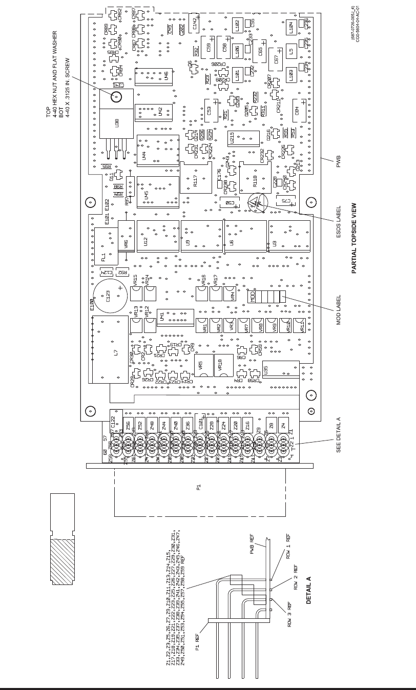
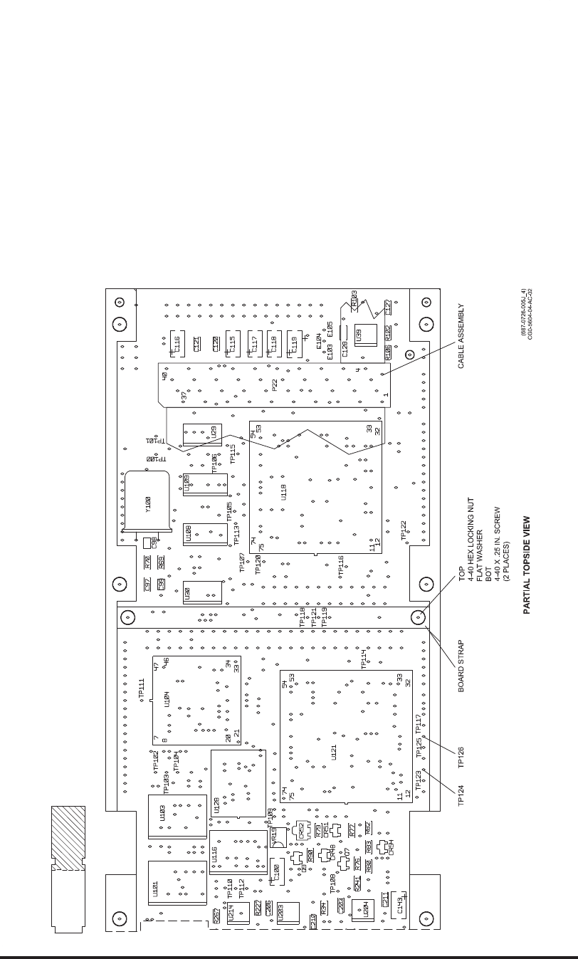
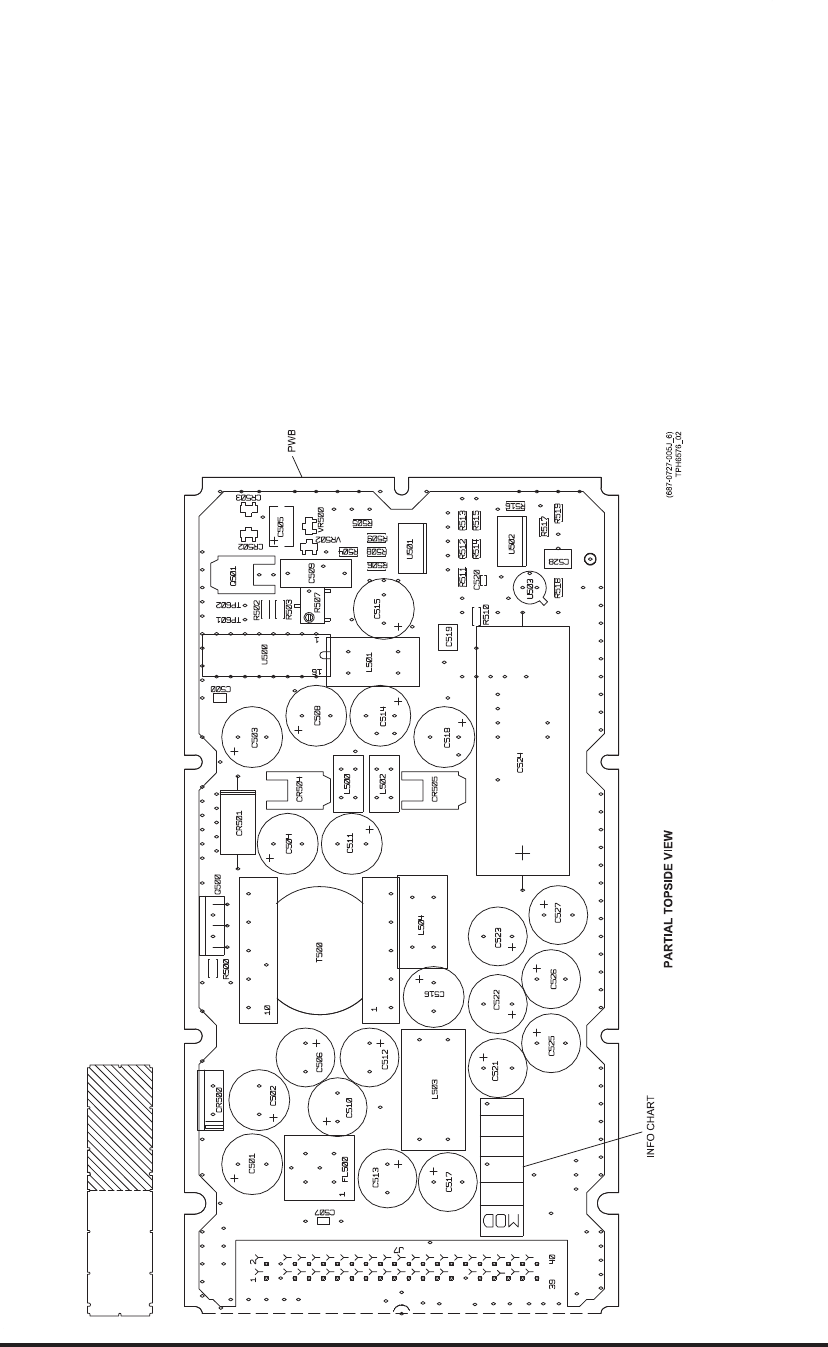
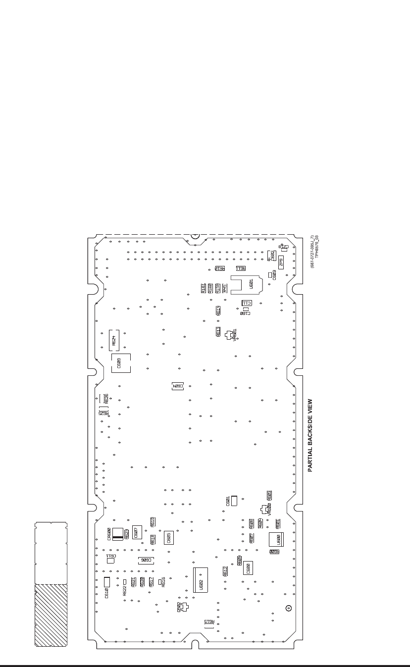
Video Processor Circuit Card A6 (CPN 687-0726-005), Maintenance Aid Diagram
Figure 2025 (Sheet 1 of 4)/GRAPHIC 34-50-96-99B-060-A01
34-50-96 Page 2173/2174
May 18/06
ROCKWELL COLLINS
COMPONENT MAINTENANCE MANUAL with IPL
TDR-94, PART NO 622-9352
Video Processor Circuit Card A6 (CPN 687-0726-005), Maintenance Aid Diagram
Figure 2025 (Sheet 2 of 4)/GRAPHIC 34-50-96-99B-060-A01
34-50-96 Page 2175/2176
May 18/06
ROCKWELL COLLINS
COMPONENT MAINTENANCE MANUAL with IPL
TDR-94, PART NO 622-9352
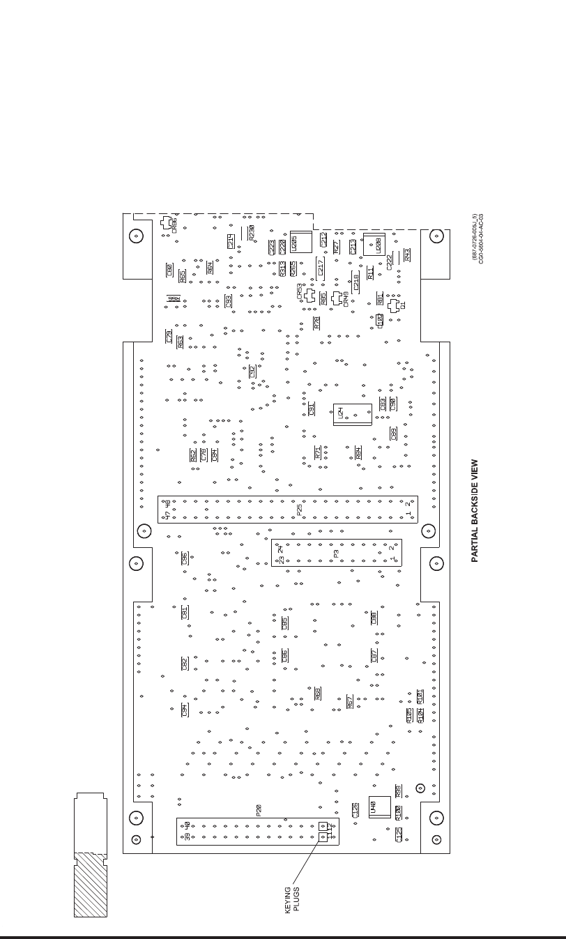
Video Processor Circuit Card A6 (CPN 687-0726-005), Maintenance Aid Diagram
Figure 2025 (Sheet 3 of 4)/GRAPHIC 34-50-96-99B-060-A01
34-50-96 Page 2177/2178
May 18/06
ROCKWELL COLLINS
COMPONENT MAINTENANCE MANUAL with IPL
TDR-94, PART NO 622-9352
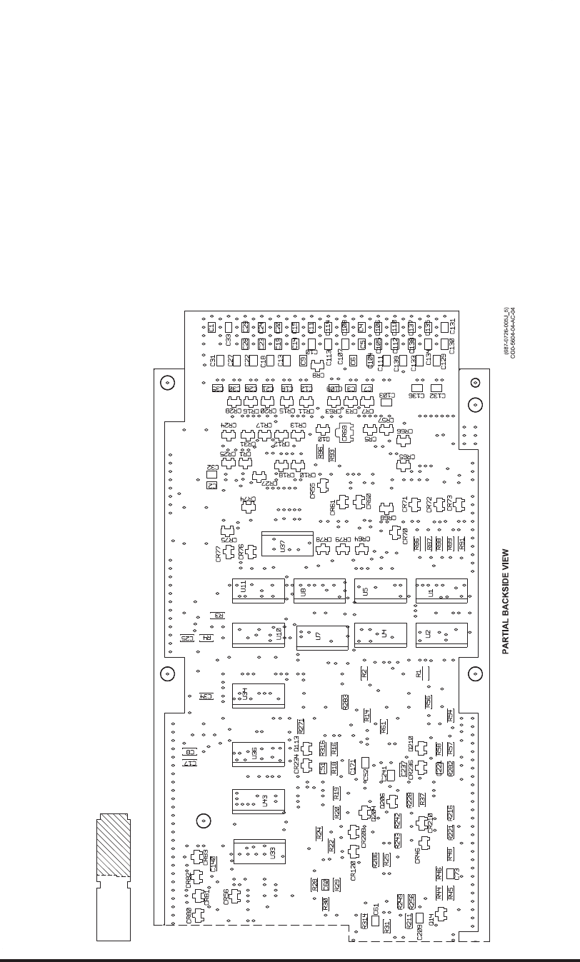
Video Processor Circuit Card A6 (CPN 687-0726-005), Maintenance Aid Diagram
Figure 2025 (Sheet 4 of 4)/GRAPHIC 34-50-96-99B-060-A01
34-50-96 Page 2179/2180
May 18/06
ROCKWELL COLLINS
COMPONENT MAINTENANCE MANUAL with IPL
TDR-94, PART NO 622-9352
Video Processor Circuit Card A6 (CPN 687-0726-005), Schematic Diagram
Figure 2026 (Sheet 1 of 7)/GRAPHIC 34-50-96-99B-061-A01
34-50-96 Page 2181/2182
May 18/06
ROCKWELL COLLINS
COMPONENT MAINTENANCE MANUAL with IPL
TDR-94, PART NO 622-9352
Video Processor Circuit Card A6 (CPN 687-0726-005), Schematic Diagram
Figure 2026 (Sheet 2 of 7)/GRAPHIC 34-50-96-99B-061-A01
34-50-96 Page 2183/2184
May 18/06
ROCKWELL COLLINS
COMPONENT MAINTENANCE MANUAL with IPL
TDR-94, PART NO 622-9352
Video Processor Circuit Card A6 (CPN 687-0726-005), Schematic Diagram
Figure 2026 (Sheet 3 of 7)/GRAPHIC 34-50-96-99B-061-A01
34-50-96 Page 2185/2186
May 18/06
ROCKWELL COLLINS
COMPONENT MAINTENANCE MANUAL with IPL
TDR-94, PART NO 622-9352
Video Processor Circuit Card A6 (CPN 687-0726-005), Schematic Diagram
Figure 2026 (Sheet 4 of 7)/GRAPHIC 34-50-96-99B-061-A01
34-50-96 Page 2187/2188
May 18/06
ROCKWELL COLLINS
COMPONENT MAINTENANCE MANUAL with IPL
TDR-94, PART NO 622-9352
Video Processor Circuit Card A6 (CPN 687-0726-005), Schematic Diagram
Figure 2026 (Sheet 5 of 7)/GRAPHIC 34-50-96-99B-061-A01
34-50-96 Page 2189/2190
May 18/06
ROCKWELL COLLINS
COMPONENT MAINTENANCE MANUAL with IPL
TDR-94, PART NO 622-9352
Video Processor Circuit Card A6 (CPN 687-0726-005), Schematic Diagram
Figure 2026 (Sheet 6 of 7)/GRAPHIC 34-50-96-99B-061-A01
34-50-96 Page 2191/2192
May 18/06
ROCKWELL COLLINS
COMPONENT MAINTENANCE MANUAL with IPL
TDR-94, PART NO 622-9352
Video Processor Circuit Card A6 (CPN 687-0726-005), Schematic Diagram
Figure 2026 (Sheet 7 of 7)/GRAPHIC 34-50-96-99B-061-A01
34-50-96 Page 2193/2194
May 18/06

ROCKWELL COLLINS
COMPONENT MAINTENANCE MANUAL with IPL
TDR-94, PART NO 622-9352
MAINTENANCE AID/SCHEMATIC CHANGES
REVISION
IDENT
(SHEET)
DESCRIPTION OF REVISION AND CAUSE FOR CHANGE SERVICE
BULLETIN
EFFECTIVITY
MARKING
A (1,6,8) R95 changed from 1 kവto 10 kവ. Note 5 is added to indicate
that connector P26 is shown for reference only. This connector
is not installed on the finished assembly.
REV A to CPN
687-0726-006
B (1,3,5,8) U104, 7130, changes from CPN 835-5891-010 to CPN
835-8515-030. Also added notes 6 and 7.
REV B to CPN
687-0726-006
N/A Internal documentation change only. REV C
to CPN
687-0726-006
D (2) Changed R227 and R230 from 10 kവto 8.25 kവ. Also added
1.82 kവresistors R317 and R318.
REV D
to CPN
687-0726-006
N/A Changed Video Circuit Card A6 to CPN 687-0726-007. CPN
687-0726-006 may be used as alternate.
REV D
to CPN
983-8019-001
Video Processor Circuit Card A6 (CPN 687-0726-006) and Video Processor Circuit Card Assembly
A6 (CPN 983-8019-001), Maintenance Aid and Schematic Changes
Table 2015/Table 34-50-96-99A-026-A01
34-50-96 Page 2195/2196
May 20/10
ROCKWELL COLLINS
COMPONENT MAINTENANCE MANUAL with IPL
TDR-94, PART NO 622-9352
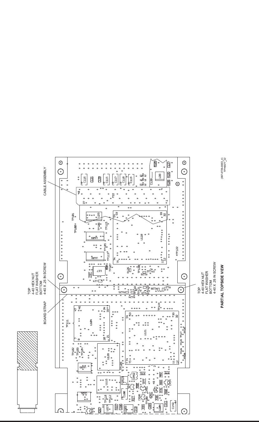
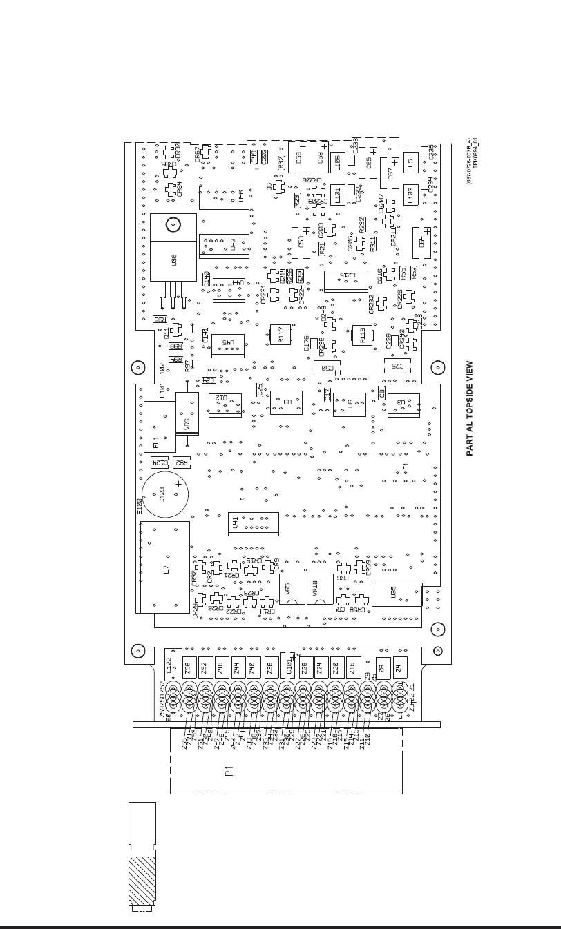
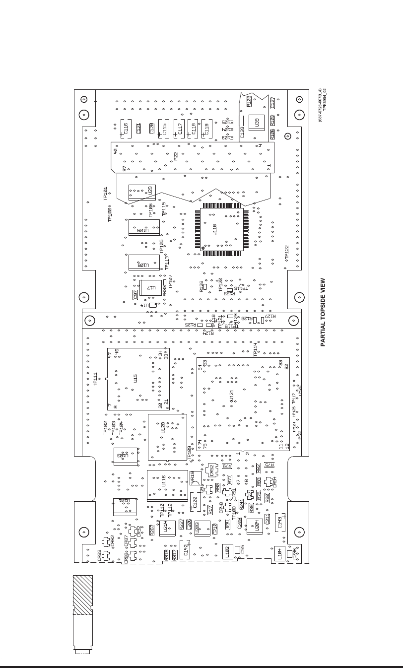
Video Processor Circuit Card A6 (CPN 687-0726-006) and Video Processor Circuit Card
Assembly A6 (CPN 983-8019-001), Maintenance Aid Diagram
Figure 2027 (Sheet 1 of 4)/GRAPHIC 34-50-96-99B-062-A01
34-50-96 Page 2197/2198
May 18/06
ROCKWELL COLLINS
COMPONENT MAINTENANCE MANUAL with IPL
TDR-94, PART NO 622-9352
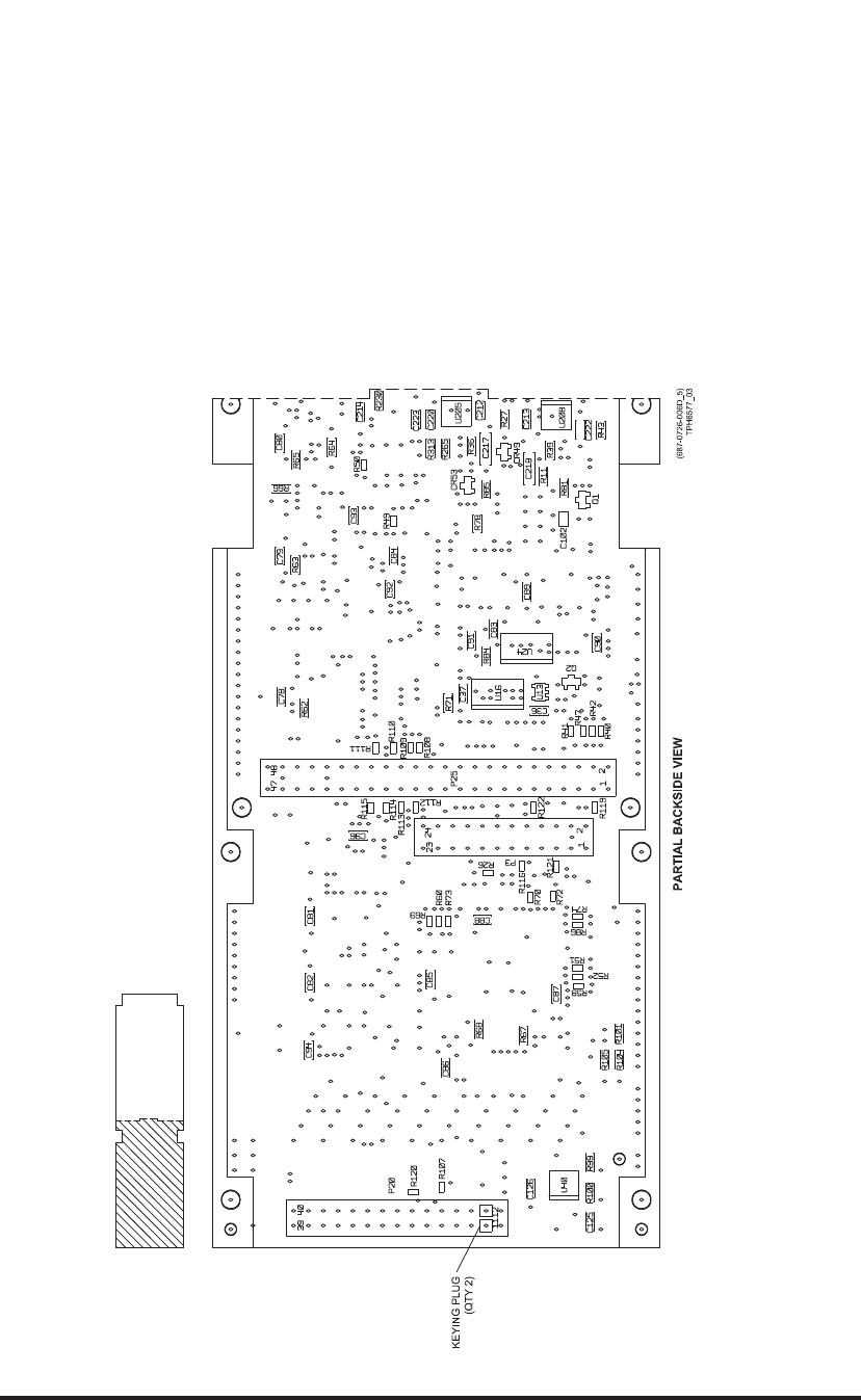
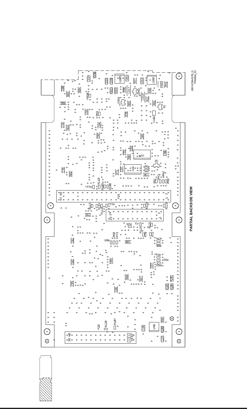
Video Processor Circuit Card A6 (CPN 687-0726-006) and Video Processor Circuit Card
Assembly A6 (CPN 983-8019-001), Maintenance Aid Diagram
Figure 2027 (Sheet 2 of 4)/GRAPHIC 34-50-96-99B-062-A01
34-50-96 Page 2199/2200
May 18/06
ROCKWELL COLLINS
COMPONENT MAINTENANCE MANUAL with IPL
TDR-94, PART NO 622-9352
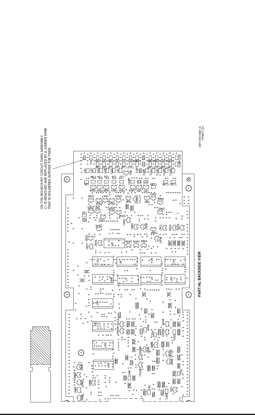
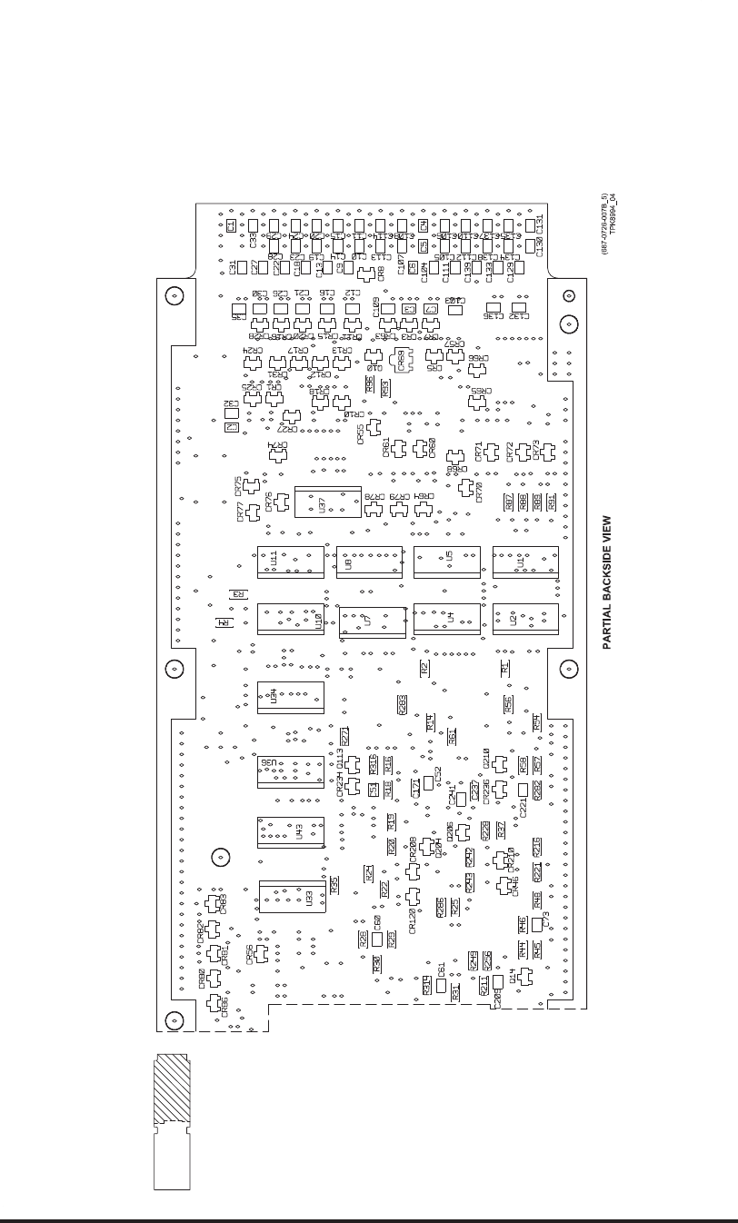
Video Processor Circuit Card A6 (CPN 687-0726-006) and Video Processor Circuit Card
Assembly A6 (CPN 983-8019-001), Maintenance Aid Diagram
Figure 2027 (Sheet 3 of 4)/GRAPHIC 34-50-96-99B-062-A01
34-50-96 Page 2201/2202
May 18/06
ROCKWELL COLLINS
COMPONENT MAINTENANCE MANUAL with IPL
TDR-94, PART NO 622-9352
Video Processor Circuit Card A6 (CPN 687-0726-006) and Video Processor Circuit Card
Assembly A6 (CPN 983-8019-001), Maintenance Aid Diagram
Figure 2027 (Sheet 4 of 4)/GRAPHIC 34-50-96-99B-062-A01
34-50-96 Page 2203/2204
May 18/06
ROCKWELL COLLINS
COMPONENT MAINTENANCE MANUAL with IPL
TDR-94, PART NO 622-9352
(828-7566-006C_1)
TPH6410_01
BAS70-04
BAS70-04
BAS70-04
BAS70-04
BAS70-04
BAS70-04
BAS70-04
BAS70-04
BAS70-04
BAS70-04
BAS70-04
BAS70-04
BAS70-04
BAS70-04
BAS70-04
BAS70-04
BAS70-04
BAS70-04
BAS70-04
BAS70-04
BAS70-04
BAS70-04
BAS70-04
BAS70-04
BAS70-04
BAS70-04
BAS70-04
BAS70-04
BAS70-04
+5VDC
+5VDC
+5VDC
+5VDC +5VDC
+5VDC
+5VDC
+5VDC
+5VDC
+5VDC
+5VDC
+5VDC
470 PF
470 PF
470 PF
470 PF
470 PF
470 PF
0.01
470 PF
470 PF
470 PF
470 PF
470 PF
470 PF
470 PF
0.01
470 PF
470 PF
470 PF
470 PF
470 PF
470 PF
470 PF
0.01
470 PF
470 PF
470 PF
470 PF
470 PF
470 PF
470 PF
470 PF
0.01
470 PF
100 K
100 K
100 K
100 K
10 K 10 K 10 K 10 K 10 K 10 K 10 K
10 K
10 K 10 K 10 K 10 K 10 K 10 K 10 K 10 K
10 K
10 K 10 K 10 K 10 K 10 K 10 K 10 K 10 K
10 K
10 K 10 K 10 K 10 K 10 K 10 K 10 K 10 K
10 K
470 PF
470 PF
SN74ABT2244ADB
OEB
OEA
VCC
GND
OA0
OA1
OA2
OA3
OB0
OB1
OB2
OB3
DB3
DB2
DB1
DB0
DA3
DA2
DA1
DA0
SN74ABT2244ADB
OEB
OEA
VCC
GND
OA0
OA1
OA2
OA3
OB0
OB1
OB2
OB3
DB3
DB2
DB1
DB0
DA3
DA2
DA1
DA0 SN74ABT2244ADB
OEB
OEA
VCC
GND
OA0
OA1
OA2
OA3
OB0
OB1
OB2
OB3
DB3
DB2
DB1
DB0
DA3
DA2
DA1
DA0
SN74ABT2244ADB
OEB
OEA
VCC
GND
OA0
OA1
OA2
OA3
OB0
OB1
OB2
OB3
DB3
DB2
DB1
DB0
DA3
DA2
DA1
DA0
3
4
UNIT AND/OR ASSEMBLY DESIGNATION.
FOR COMPLETE DESIGNATION, PREFIX WITH
PARTIAL REFERENCE DESIGNATIONS ARE SHOWN;
ARE IN MICROHENRYS.
ARE IN MICROFARADS, AND INDUCTANCE VALUES
VALUES ARE IN OHMS, CAPACITANCE VALUES
UNLESS OTHERWISE SPECIFIED, RESISTANCE1
2
NOTES:
BAS70-04
BAS70-04
622-9210-001/002/003/004/005/006/007/106 AND
HIGH SPEED SEL_F".
A TWISTED PAIR WIRE MAY BE USED IN THE FUTURE.
P26 IS FOR REFERENCE ONLY.
NOT INSTALLED ON THIS ASSEMBLY.
FOR T/L CPN 622-9210-008/108 AND CPN 622-
9352-008/108 LABEL SHOULD BE "ALT PORT A/B
FOR T/L CPN
C1 IS SHORTED TO GROUND ON 983-8019-001.
CPN 622-9352-001/002/003/004/005/006/007
LABEL SHOULD BE "ACQ-SQUIT_EN_F".
6
5
7
2
13
CR2
2
13
CR1
(3,7)
12
Z53
12
Z52
2
4
6
8
11
13
15
17
119
3
5
7
9
12
14
16
18
20
10
U9
2
4
6
8
11
13
15
17
119
3
5
7
9
12
14
16
18
20
10
U12
2
4
6
8
11
13
15
17
119
3
5
7
9
12
14
16
18
20
10
U6
2
4
6
8
11
13
15
17
119
3
5
7
9
12
14
16
18
20
10
U3
DB0
DB3
DB7
DB1
DB2
DB3
DB4
DB5
DB6
DB7
DB0
DB6
DB5
DB4
DB2
DB1
DB7
DB6
DB5
DB4
DB3
DB2
DB1
DB0
DB7
DB6
DB5
DB4
DB3
DB2
DB1
DB0
DB[0:7]
1
2
C7
1
2
C16
MODE_S_ADDR_B15
SADD_9-16_EN
SADD_17-24_EN
12
Z56
TYPE_READ_F
12
Z40
MODE_S_ADDR_B8
12
Z59
12
Z57
12
Z55
12
Z54
12
Z51
12
Z50
12
Z49
12
Z48
12
Z47
12
Z46
12
Z45
12
Z44
12
Z43
12
Z42
12
Z41
12
Z39
12
Z38
12
Z37
12
Z36
12
Z35
12
Z34
12
Z33
12
Z24
12
Z23
12
Z22
12
Z21
12
Z20
1
2
3
4
5
6
7
89
10
11
12
13
14
15
16
U11
16
8
U10
16
7
U10
16
6
U10
16
5
U10
16
4
U10
16
3
U10
16
2
U10
16
1
U10
1
2
3
4
5
6
7
89
10
11
12
13
14
15
16
U8
16
8
U7
16
7
U7
16
6
U7
16
5
U7
16
4
U7
16
3
U7
16
2
U7
16
1
U7
1
2
3
4
5
6
7
89
10
11
12
13
14
15
16
U5
16
8
U4
16
7
U4
16
6
U4
16
5
U4
16
4
U4
16
3
U4
16
2
U4
16
1
U4
1
2
3
4
5
6
7
89
10
11
12
13
14
15
16
U2
16
7
U1
16
6
U1
16
5
U1
16
4
U1
16
3
U1
16
2
U1
16
1
U1
1
2
R4
1
2
R3
1
2
R2
1
2
R1
1
2
C35
1
2
C34
1
2
C33
1
2
C32
1
2
C31
1
2
C30
1
2
C29
1
2
C28
1
2
C27
1
2
C26
1
2
C25
1
2
C24
1
2
C23
1
2
C22
1
2
C21
1
2
C20
1
2
C19
1
2
C18
1
2
C17
1
2
C15
1
2
C14
1
2
C13
1
2
C12
1
2
C11
1
2
C10
1
2
C9
1
2
C8
1
2
C6
1
2
C5
1
2
C4
1
2
C3
1
2
C2
1
2
C1
TYPE_3
TYPE_2
TYPE_1
TYPE_0
SADD_1-8_EN
MODE_S_ADDR_B9
MODE_S_ADDR_B7
MODE_S_ADDR_B6
MODE_S_ADDR_B5
MODE_S_ADDR_B4
MODE_S_ADDR_B3
MODE_S_ADDR_B23
MODE_S_ADDR_B22
MODE_S_ADDR_B21
MODE_S_ADDR_B20
MODE_S_ADDR_B2
MODE_S_ADDR_B19
MODE_S_ADDR_B18
MODE_S_ADDR_B17
MODE_S_ADDR_B16
MODE_S_ADDR_B14
MODE_S_ADDR_B13
MODE_S_ADDR_B12
MODE_S_ADDR_B11
MODE_S_ADDR_B10
MODE_S_ADDR_B1
FMS/IRS_LO/HI_SEL
EX_SQUIT_DISABLE_F
AIS/ADS_LO/HI_SEL
2
13
CR15
2
13
CR14
2
13
CR13
2
13
CR12
2
13
CR11
2
13
CR10
2
13
CR9
2
13
CR8
2
13
CR7
2
13
CR6
2
13
CR4
2
13
CR5
2
13
CR3
2
13
CR31
2
13
CR30
2
13
CR29
2
13
CR28
2
13
CR27
2
13
CR26
2
13
CR25
2
13
CR24
2
13
CR23
2
13
CR22
2
13
CR21
2
13
CR20
2
13
CR18
2
13
CR19
2
13
CR17
2
13
CR16
MODE_S_ADDR_B24
(8)
(8)
(8)
(8)
(8)
(8)
(8)
(8)
(8)
(8)
(8)
(8)
(8)
(8)
(8)
(8)
(8)
(8)
(8)
(8)
(8)
(8)
(8)
(8)
(8)
(8)
(8)
(8)
(8)
(8)
(8)
(8)
(8)
(8)
(8)
7
CONFIGURATION RESISTORS FOR CURRENT ASSEMBLY
R67 AND R68 ARE INSTALLED. ALL OTHERS (R5 - R10,
R12 - R13, R15) ARE RESERVED FOR FUTURE
CONFIGURATIONS.
B
A
B
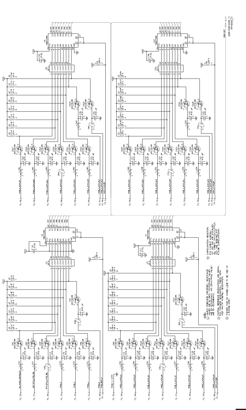
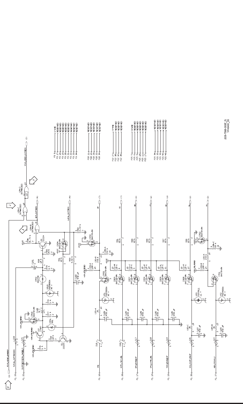
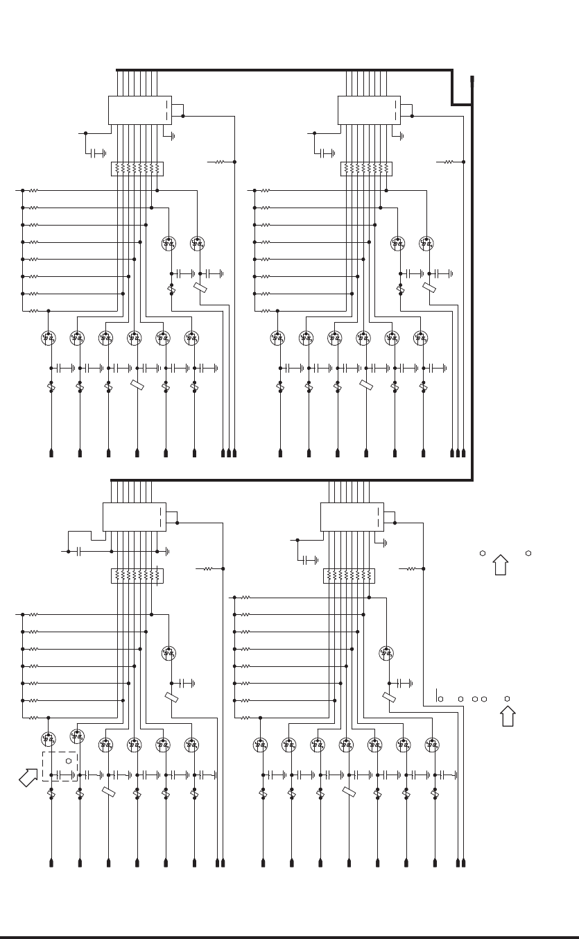
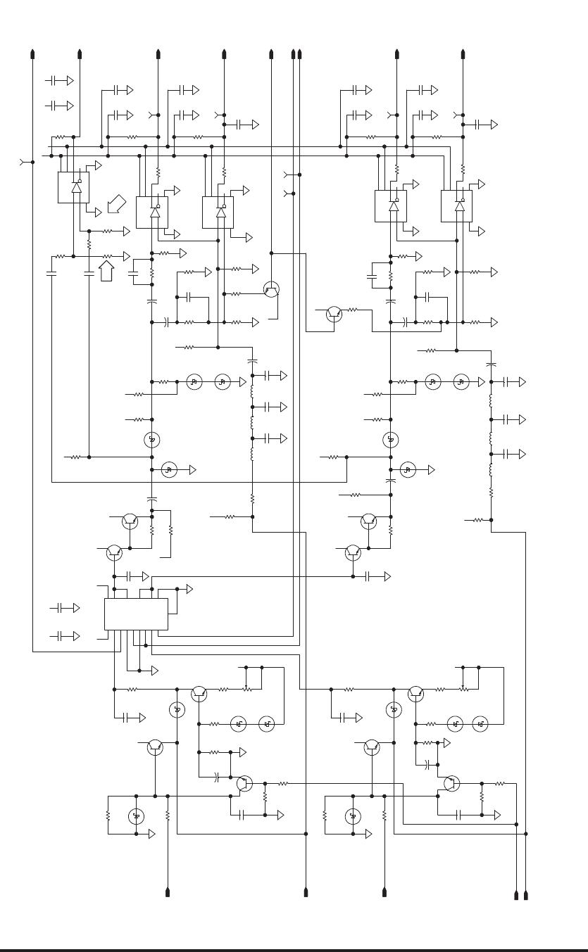
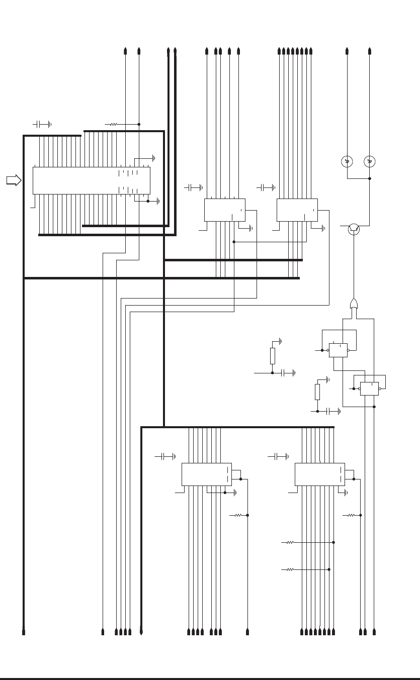
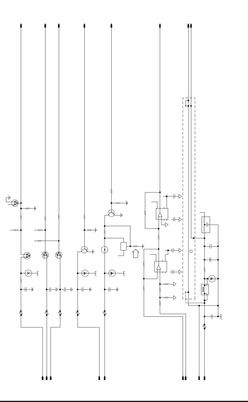
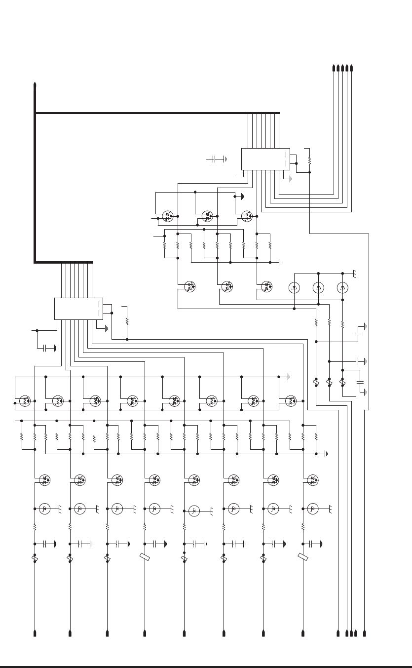
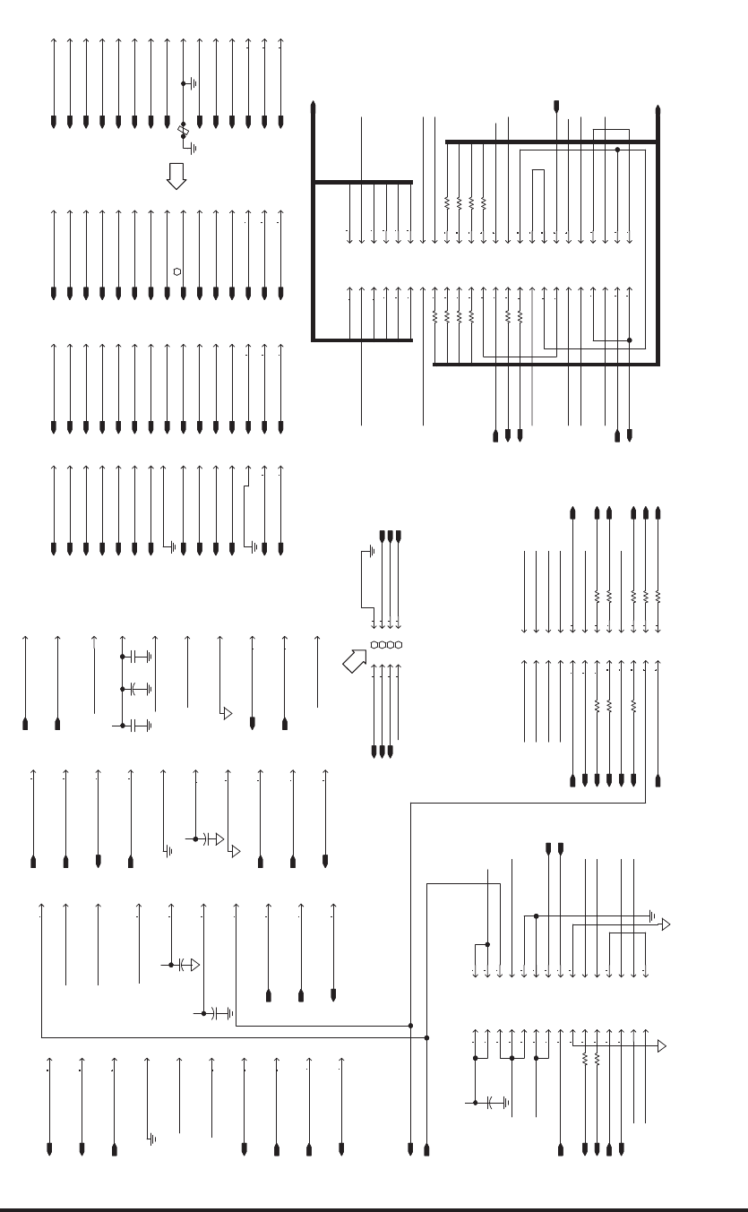
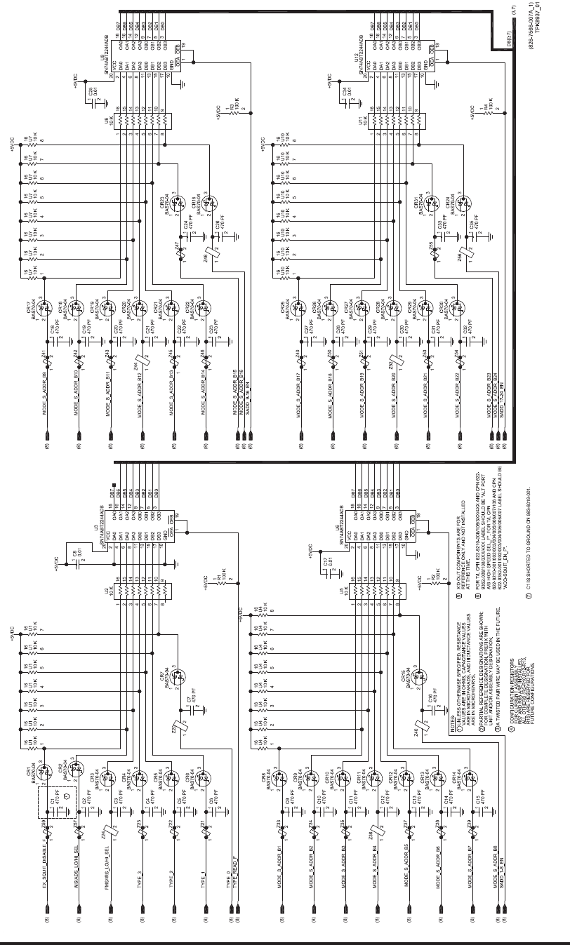
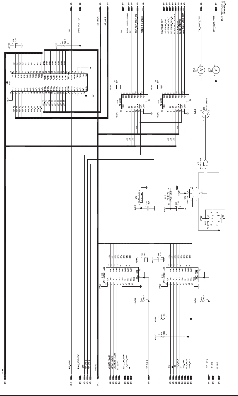
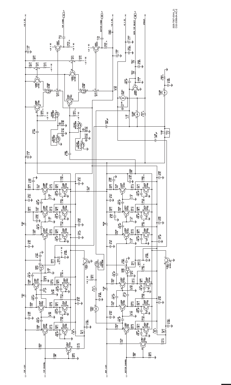
Video Processor Circuit Card A6 (CPN 687-0726-006) and Video Processor Circuit Card
Assembly A6 (CPN 983-8019-001), Schematic Diagram
Figure 2028 (Sheet 1 of 8)/GRAPHIC 34-50-96-99B-063-A01
34-50-96 Page 2205/2206
May 18/06
ROCKWELL COLLINS
COMPONENT MAINTENANCE MANUAL with IPL
TDR-94, PART NO 622-9352
(828-7566-006C_2)
TPH6410_02
0.0
-5VDC
-5VDC
-5VDC
A
A
A
A
A
A
A
A
A
A
A
AAA
A
A A
A
A
AA
A
A
A
A
A
A
A
A
AA
AA
A
A
A
A
A
AA
A
A
A
A
AA
A
+12VDC
+12VDC
+12VDC
+12VDC
+12VDC
+12VDC
+12VDC
+12VDC
-12VDC
-12VDC
-12VDC
-12VDC
-12VDC
-12VDC
-12VDC
-12VDC
-12VDC
-12VDC
-12VDC
-12VDC
+5VDC
+5VDC
+5VDC
+5VDC
+5VDC
0.1
6.8
+
220 PF 220 PF
15
+
47 PF
15
+
15
+
47 PF
27 PF
15
+
15
+
15
+
47 PF
6.8
+
0.01
10 PF
0.1
0.01
0.01
27 PF
0.01
0.01
0.01
0.01
0.01
0.0015
0.0015
0.01
220 PF
0.01
0.01
10 PF
33 PF 33 PF
33 PF 33 PF 47 PF
0.01
220 PF
301
301
301
301
301
301
301
301
301
301
301
301
301
301
301
33
15 15
15 15
33
2222A
2222A
2222A
2222A
2222A
2222A
2222A
2222A
1 K
221
10 K
33.2
10 K
100 K
47.5 K
2 K
2 K27.4 K
2.21 K
56.2 K 3.92 K 3.92 K
3.92 K
2 K
2 K 976
100 K
56.2 K
3.92 K
3.92 K 3.92 K
2.21 K
221
2.21 K
10 K
10 K
28.7 K
976
2.21 K
1 K
10 K
27.4 K
1 K
2 K
2 K
2 K
2 K
1 K
28.7 K
33.2
10 K
1 K
2.21 K
2.21 K
47.5 K
1 K
2 K
10 K
1016
LE GND
V-
V+
+
-
1016
LE GND
V-
V+
+
-
1016
LE GND
V-
V+
+
-
MC74HC4316AD
VEE
GND
VCC
ENBL
YD
YC
YB
YA
DCTRL
XD
CCTRL
XC
BCTRL
XB
ACTRL
XA
2222A
1016
LE GND
V-
V+
+
-
20 K
20 K
A
A
1016
LE GND
V-
V+
+
-
A
A
0.0
A
2 K
2222A
A
A
0.0
0.0
6.8
+
10 K
6.8
+
2222A
A
2222A
301
1.82 K
+5VDC
-5VDC
12.1 K
A
1.82 K
8.25 K 8.25 K
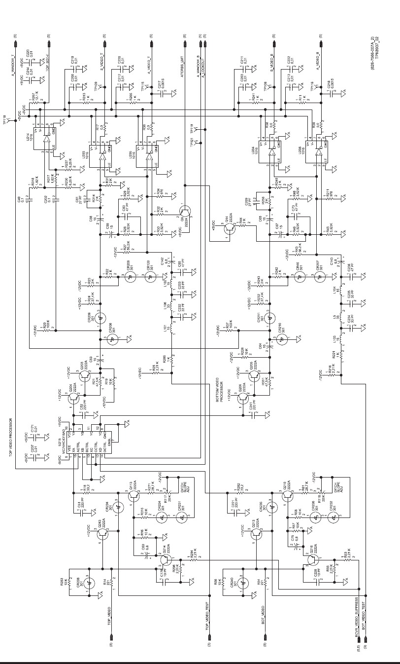
TOP VIDEO PROCESSOR
DITCH
SLOPE
ADJ
DITCH
SLOPE
ADJ
BOTTOM VIDEO
PROCESSOR
1
2
R227
1
2
R230
1
2
R318 1
2
R267
12
R317
3
1
CR231
2
1
3
Q214
(8)
(5)
2
1
3
Q216
1
2C75 1
2
R57
1
2
C143
A_VIDEO_T
S_VIDEO_B
A_VIDEO_B
21
R39
12
R38
2
1
3
Q14
1
2
R44
ATCRBS_LMT
12
R17
S_VIDEO_T
3
2
5
8
7
1
4
6
U203
3
2
1
R118
1
2
3
R117
3
2
5
8
7
1
4
6
U214
2
1
3
Q243
A_WINDOW_B
A_LOCKOUT
BOT_VIDEO_TEST
TOP_VIDEO_TEST
1
15
4
5
10
6
13
14
7
12
11
3
2
16
9
8
U215
3
2
5
8
7
1
4
6
U208
3
2
5
8
7
1
4
6
U205
3
2
5
8
7
1
4
6
U204
1
2
R316
12
R314
1
2
R313
12
R311
12
R296
1
2
R294
12
R286
12
R283
1
2
R282
1
2
R271
1
2
R265
12
R256
1
2
R249
1
2
R243
1
2
R242
1
2
R241
1
2
R232
1
2
R228
12
R221
1
2
R216
1
2
R211
1
2
R61
1
2
R58
12
R56
12
R55
12
R54
1
2
R53
1
2
R48
1
2
R46
1
2
R45
1
2
R43
1
2
R37
1
2
R34
1
2
R32
1
2
R31
1
2
R30
1
2
R29
1
2
R28
1
2
R27
1
2
R25
1
2
R24
1
2
R23
1
2
R22
12
R21
1
2
R20
12
R19
1
2
R18
1
2
R16
12
R14
1
2
R11
2
1
3
Q213
2
1
3
Q210
2
1
3
Q206
2
1
3
Q205
2
1
3
Q204
2
1
3
Q203
2
1
3
Q113
2
1
3
Q6
12
L106
12
L104
12
L103
12
L102
12
L101
12
L5
3
1
CR240
3
1
CR238
3
1
CR236
31
CR234
3
1
CR232
3
1
CR226
3
1
CR224
31
CR211
3
1
CR210
3
1
CR209
3
1
CR208
3
1
CR207
3
1
CR206
3
1
CR120
3
1
CR46
1
2
C241
1
2
C237
1
2
C236
1
2
C235
1
2
C234
1
2
C233
1
2
C232
1
2
C228
1
2
C223
1
2
C222
1
2
C221
1
2
C220
1
2
C218
1
2
C217
1
2
C214
1
2
C213
1
2
C212
1
2
C211
1
2
C210
12
C209
1
2
C206
1
2
C203
12
C202
1
2
C176
1
2
C171
12
C142
1
2
C73
1
2C67
1
2
C65
1
2
C64
12
C61
1
2
C60
1
2C59
1
2
C58
1
2
C55
1
2
C53
1
2
C52
1
2
C51
1
2C50
12
C49
TOP_VIDEO
RCVR_VIDEO_SUPPRESS
BOT_VIDEO
A_WINDOW_T
1
TP108
1
TP109
1
TP115
1
TP116
1
TP118
1
TP119
1
TP121
21
R36
(5,8)
(3)
(8)
(3)
(8)
(5)
(5)
(5)
(5)
(5)
(5)
(5)
D
D
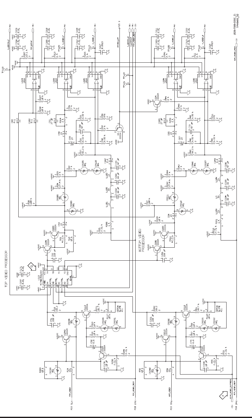
Video Processor Circuit Card A6 (CPN 687-0726-006) and Video Processor Circuit Card
Assembly A6 (CPN 983-8019-001), Schematic Diagram
Figure 2028 (Sheet 2 of 8)/GRAPHIC 34-50-96-99B-063-A01
34-50-96 Page 2207/2208
May 18/06
ROCKWELL COLLINS
COMPONENT MAINTENANCE MANUAL with IPL
TDR-94, PART NO 622-9352
(828-7566-006C_3)
TPH6410_03
+5VDC
+5VDC
74HCT74
GND
+5VDC
0.01
+5VDC
+5VDC
+5VDC
+5VDC
+5VDC
+5VDC
+5VDC
+5VDC
+5VDC
+5VDC
+5VDC
+5VDC
+5VDC
+5VDC
+5VDC
+5VDC
0.01
0.01
0.01
0.01
0.01
301
301
100 K
100 K
10 K 10 K
100 K
SN74ABT2244ADB
OEB
OEA
VCC
GND
OA0
OA1
OA2
OA3
OB0
OB1
OB2
OB3
DB3
DB2
DB1
DB0
DA3
DA2
DA1
DA0
SN74ABT2244ADB
OEBOEA
VCC
GND
OA0
OA1
OA2
OA3
OB0
OB1
OB2
OB3DB3
DB2
DB1
DB0
DA3
DA2
DA1
DA0
NC7ST32M5
+5VDC
NC7ST32M5
GND
VCC
MMBT2369AL
74HC259
GND
VCC
G
Q0
Q1
Q2
Q3
Q4
Q5
Q6
Q7
S0
S1
S2
CLR
DATI
74HC259
GND
VCC
G
Q0
Q1
Q2
Q3
Q4
Q5
Q6
Q7
S0
S1
S2
CLR
DATI
74HCT74
Q
Q
R
S
C
D
74HCT74
Q
Q
R
S
C
D
0.01
7130
BSYR
INTR
R/WR
OER
CER
A0R
A1R
A2R
A3R
A4R
A5R
A6R
A7R
A8R
A9R
I/O0R
I/O1R
I/O2R
I/O3R
I/O4R
I/O5R
I/O6R
I/O7R
CEL
OEL
INTL
R/WL
BSYL
I/O7L
I/O6L
I/O5L
I/O4L
I/O3L
I/O2L
I/O1L
I/O0L
A9L
A8L
A7L
A6L
A5L
A4L
A3L
A2L
A1L
A0L
NC
NC
NC
NC
GND
VCC
MP_A0-A9
MP_D0-D7
7
8
9
10
11
12
13
14
15
16
1
2
45
44
43
42
41
40
39
38
37
36
51
50
646
48
49
34
33
32
31
30
29
28
27
4
3
24
23
22
21
20
19
18
17
52
26
47
5
25
35
U104
(1,7)
(8)
2
1C37
2
3
1
6
5
4
U16
10
9
8
13
11
12
U16
1
2
3
13
15
14
12
11
10
9
7
6
5
416
8
U109
1
2
3
13
15
14
12
11
10
9
7
6
5
416
8
U108
2
1
3
Q2
53
U13
1
24
U13
2
4
6
8
11
13
15
17
119
3
5
7
9
12
14
16
18
20
10
U101
2
4
6
8
11
13
15
17
119
3
5
7
9
12
14
16
18
20
10
U103
1
2
R66
1
2
R65
1
2
R64
1
2
R63
1
2
R62
3
1
CR49
3
1
CR48
1
2
C82
1
2
C81
1
2
C80
1
2
C79
1
2
C78
(4)
(4)
1
2
C36
14 7
U16
(2)
(2)
(8)
(4)
(5)
(5)
(5)
(5)
(5)
(5)
(6)
(6)
(4)
(5)
(8)
(8)
(8)
(5)
(5)
(5)
(5)
(5)
(8)
(8)
(8)
(8)
(8)
(8)
(8)
(4)
(4)
(5)
(4)
(5)
(8)
(8)
(8)
(8)
(8)
(4,5)
(4)
VP_RD_D
TOP_LOW_PWR
ST_SUPP
MM
MESSG_READY
LL
KK
JJ
HH
DISCRETE_ADDR
BDCST_ADDR
+5_V_MON
BOT_LOW_PWR
VP_WR_D
DUAL_PORT_EN
ALL_CALL_LOCK_OUT
ATCRBS_OFF
BOT_VIDEO_TEST
DD
DLINK_LENGTH
EE
MODE_S_ENABLE
RCVR_VIDEO_INHIBIT
SELFTEST_BOT
SELFTEST_GEN_B
SELFTEST_GEN_T
SELFTEST_TOP
TOP_BOT_TEST_SEL
TOP_VIDEO_TEST
RCVR_TEST_ENABLE
A[0:9]
A2
A1
A0
A2
A1
A0
A1
A2
A3
A4
A5
A6
A7
A8
A9
A0
WRL
VP_WR_E
+70V_MON
DB0
DB0
DB7
DB3
DB0
DB1
DB2
DB4
DB5
DB6
DB7
DB7
DB6
DB5
DB4
DB3
DB2
DB1
DB0
DB6
DB5
DB4
DB3
DB2
DB1
DB0
DB[0:7]
RAM_SELECT-F
MP_WR-F
MP_A0
MP_A1
MP_A2
MP_A3
MP_A4
MP_A5
MP_A6
MP_A7
MP_A8
MP_A9
MP_D7
MP_D6
MP_D5
MP_D4
MP_D3
MP_D2
MP_D0
MP_D1
VP_RD_C
P/S_MON
+35V_MON
P1/3/4
10_MHZ
RST
VCC
B
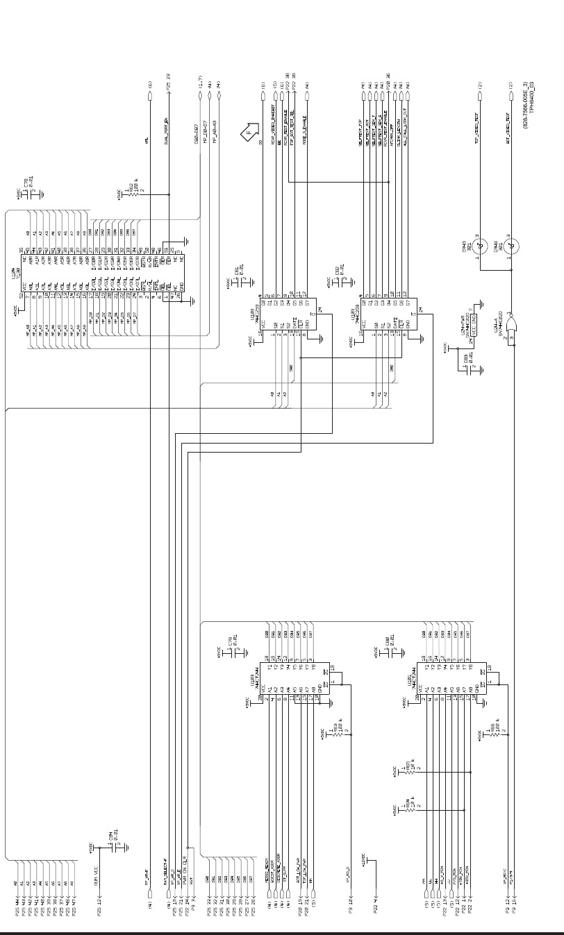
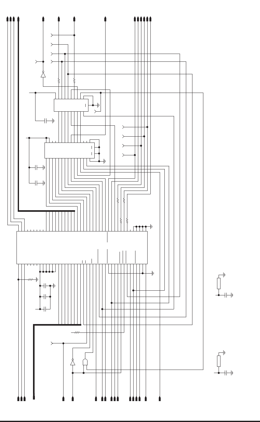
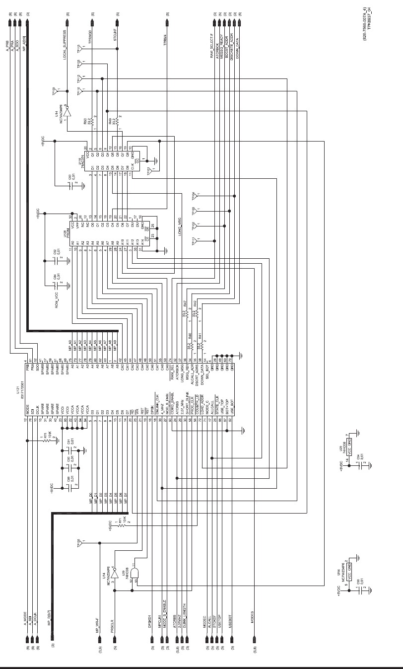
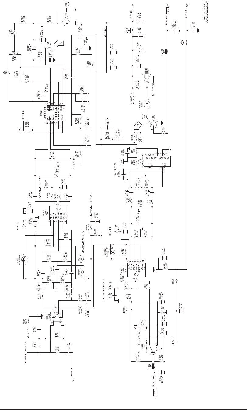
Video Processor Circuit Card A6 (CPN 687-0726-006) and Video Processor Circuit Card
Assembly A6 (CPN 983-8019-001), Schematic Diagram
Figure 2028 (Sheet 3 of 8)/GRAPHIC 34-50-96-99B-063-A01
34-50-96 Page 2209/2210
May 18/06
ROCKWELL COLLINS
COMPONENT MAINTENANCE MANUAL with IPL
TDR-94, PART NO 622-9352
(828-7566-006C_4)
TPH6410_04
0.01
+5VDC
+5VDC
0.01
0.01
0.01
0.01
74HC08
GND
VCC
74AC374
CLK
OC
Q8
Q7
Q6
Q5
Q4
Q3
Q2
Q1
D8
D7
D6
D5
D4
D3
D2
D1
GND
VCC
PROM
NC
NC
DU
DU
A0
A1
A2
A3
A4
A5
A6
A7
A8
A9
A10
A11
A12
A13
A14
O0
O1
O2
O3
O4
O5
O6
O7
OE
CE
VPP
VCC
GND
+5VDC
0.01
74HC08
+5VDC
+5VDC
+5VDC
NC7WZ04P6
NC7WZ04P6
VCC GND
NC7WZ04P6
0.01
0.01
33.2
33.2
33.2
33.2
33.2
33.2
10 K
10 K
8317172001
DOWN_DATA
CA8
CA7
CA6
CA5
CA4
D3
CA1
CA3
CA2
CA0
A9
A8
A7
A6
A5
A4
A3
DPSK
RST
RST
WR
RD
D7
D6
D5
D4
D2
D1
D0
ATCRBCK
RAM_SEL
MODE_C
CA9
VCCA
VCCA
VCCA
VCCA
A2
A1
A0
SPARE
SDI
DCLK
SPARE
SPARE
SPARE
VCCI
VCCI
SPARE
SPARE
SPARE
SPARE
SPARE
SDO
PRA
PRB
USE_BOT
BOT>TOP
STATE_CLK
ALLCALL
GND
GND
GND
GND
SEL_BOT
USE_TOP
DNLINK_CLK
4_MHZ
GND
LOAD_ADDR
COUNTR_LD
PROC_CLR
SHORT_DLINK
2.07_MHz
ATCRBS
COMD_ENABL
MOD_S_ENBL
DSCRT_ADRS
ALCALL_ADR
MSG_RDY
LONG_MSG
MODE
SPARE
ROM_VCC
MP_A0-A9
12
76
10
15
31
33
40
23
65
22
43
64
84
5
3
7
8
9
13
11
14
20
25
21
19
16
18
39
27
60
24
29
30
58
56
72
71
17
26
66
67
62 70
63
49
28
6
54
38
35
34
36
37
32
74
53
55
51
50
46
48
47
44
45
42
2
1
83
82
80
79
78
77
73
75
69
68
61
59
57
41
52
81
4
U121
MP_A0
MP_A9
MP_A8
MP_A7
MP_A6
MP_A5
MP_A4
MP_A3
MP_A2
MP_A1
2
1
R75
A_DCLK
1
2
R71
21
R50
12
R49
12
R42
12
R47
12
R41
DOWN_DATA
DISCRETE_ADDR
MESSG_READY
RAM_SELECT-F
ATCRBCK
BDCST_ADDR
12
R40
MP_D0
MP_D[0:7]
MP_D7
MP_D6
MP_D5
MP_D4
MP_D3
MP_D2
MP_D1
MODES
MODE_S_ENABLE
ALCALL
1
2
C90
1
2
C94
16
U14
52
U14
34
U14
A_SDO
A_PRA
MPCLK4
1
TP126
(3)
A_SDI
A_PRB
(3)
LOCAL_SUPPRESS
1
TP113
1
TP112
1
TP125
1
TP110
TPRM4
1
TP111
1
TP104
LONG_MSG
USEBOT
USETOP
STCKDF
MODEC
DLINK_LENGTH
2.07MHZ
DPSKD1
PRSCLR
12
13
11
U29
1
2
C89 11
10
9
8
7
6
5
4
29
28
24
27
3
30
31
23 25
22
21
20
19
18
15
14
13
32
2
16
17
1
12
26
U128
3
4
7
8
13
14
17
18
11
1
19
16
15
12
9
6
5
2
20
10
U116
14 7
U29
1
2
C96
1
2
C93
1
2
C92
1
2
C91
1
TP101
1
TP102
1
TP103
1
TP105
MP_WR-F
ATCRBS
1
2
C84
STCLKF
TPRMQ0
A_MODE
(8)
(8)
(8)
(3,5)
(5)
(5)
(5)
(5)
(5)
(3)
(5)
(5,8)
(5)
(5,8)
(5)
(5)
(3)
(8)
(8)
(8)
(3)
(5)
(5)
(5)
(5)
(5)
(3)
(3)
(3)
(5)
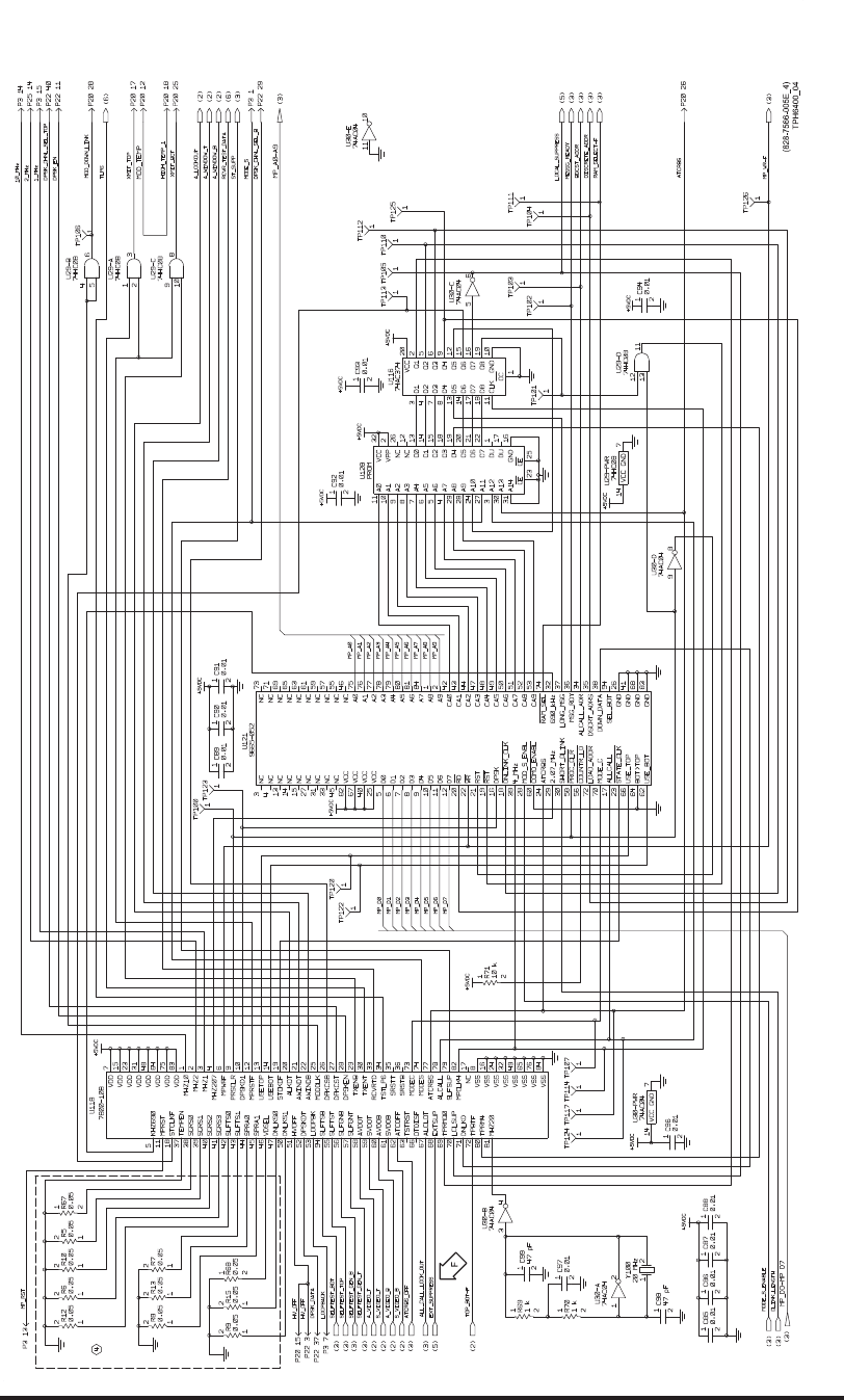
Video Processor Circuit Card A6 (CPN 687-0726-006) and Video Processor Circuit Card
Assembly A6 (CPN 983-8019-001), Schematic Diagram
Figure 2028 (Sheet 4 of 8)/GRAPHIC 34-50-96-99B-063-A01
34-50-96 Page 2211/2212
May 18/06
ROCKWELL COLLINS
COMPONENT MAINTENANCE MANUAL with IPL
TDR-94, PART NO 622-9352
(828-7566-006C_5)
TPH6410_05
4
+5VDC
62 K
+5VDC
+5VDC
33.2
+28V_FILTERED
+28V_FILTERED
+28V_FILTERED
+28V_FILTERED SN74HC02D
BAS70-04
BAS70-04
BAS70-04
BAS70-04
BAS70-04
BAS70-04
BAS70-04
BAS70-04
BAS70-04
+5VDC
+5VDC
+5VDC
4.7
+
1
+
470 PF
470 PF
470 PF
470 PF
470 PF
470 PF
470 PF
470 PF
301
2907
3.92 K
3.92 K
4.75 K
475
10 K
10 K
10 K
10 K
10 K
10 K
10 K
100 K
62 K
62 K
36 270 K
P6SMB36A
36 V
SN74HC02D SN74HC02D
74HC08
+5VDC
0.01 0.01 0.010.01
P6SMB36A
36 V
+5VDC
BAS70-04
+5VDC
270 K
270 K
10 K
36
36
100 K
+28V_FILTERED
10 K
P6SMB36A
36 V
P6SMB36A
36 V
+5VDC
+5VDC
20 MHZ
OUT
GND
V+
ENBL
0.0 0.0 0.0 0.0 0.0
0.0 0.0 0.0
0.0 0.0 0.0
0.01
74HC08
BAW78D
2222A
2222A
1 K
10 K
1 K1 K
10 K
1 K
10 K
BAS70-04
100 K
BAS70-04
74HC08
33.2
33.2
33.2
33.2
33.2
33.2
33.2
7800-10B
VDD
VDD
VDD
VDD
VDD
VDD
VDD
VDD
VSS
VSS
VSS
VSS
VSS
VSS
VSS
VSS
NC
MPCLK4
SLFSUP
ALCALL
ATCRBS
MODES
MODEC
SRSTB
SRSTT
TSTLP6
RCVRTD
TXENT
TXENB
DPSKEN
DPKCST
DPKCSB
MODDLK
AWINDB
AWINDT
ALKOT
STCKDF
USEBOT
USETOP
MPRST F
DPSKD1
PRSCLR
MPWRF
MHZ207
MHZ1
MHZ2
MHZ10
MHZ20
TPRM4
TPBTF
DNLKD
LCLSUP
TPRMQ0
EXTSUP
ALCLOT
OTDISF
TSTRST
ATCOFF
SVDOB
AVDOB
SVDOT
AVDOT
SLFGNT
SLFGNB
SLFTST
SLFTSB
LOOPBK
DPSKDT
HVOFF
DNLKS1
DNLKS0
VDSEL
SPRA1
SPRA0
SLFTS1
SLFTS0
SGRS3
SGRS2
SGRS1
SGRS0
TEMPEN
STCLKF
MPRST
KHZ690
33.2
33.2
33.2
33.2
33.2
SN74HC02D
GND
VCC
0.01
SN74HC02D
AIR_GROUND_2
EXT_SUPPRESS
EXT_SUPPRESS
12
Z29
MUTUAL_SUPPRESSION
2
31
U24
1
2
C83
14 7
U24
(3)
10_MHZ
12
R26
(3)
SELFTEST_INH-F
21
R12612
R73
1
TP106
1
TP123
DPSKD1
PRSCLR
12
R72
2
1
R74
1
TP100
1
TP120
1
TP122
5
11
18
37
38
39
40
41
42
43
44
45
46
47
50
51
52
53
54
55
56
57
58
59
60
61
62
63
66
67
68
69
70
71
72
80
81
82
79
78
77
74
73
36
35
34
33
30
29
28
27
26
25
22
21
20
19
14
13
12
10
9
6
4
3
2
1
7
15
23
31
48
64
75
83
8
16
24
32
49
65
76
84
17
U118
1
TP114
1
TP124
1
TP117
12R86
USEBOT
USETOP
12
R51
21
R60
21
R70
12
R69
12
R59 21
R52 A_WINDOW_T
9
10 8
U29
21
3
CR32
12
R35
2
13
CR60
12
R90
1
2
R79
12
R81
1
2
R77
1
2
R78
1
2
R80
1
2
R76
2
1
3
Q1
2
1
3
Q923
CR52
XMIT_TOP
XMIT_BOT
1
23
U29
1
2
C97
1
2
R68
1
2
R15
1
2
R9
1
2
R7
1
2
R13
1
2
R8
1
2
R67
1
2
R5
1
2
R10
1
2
R6
1
2
R12
LOCAL_SUPPRESS
1
3
4
2
U17
1
2
VR1
1
2
VR2
LL
16
12
U1
2
15
U33
215
U35
314
U35
12
R87
710
U46
116
U36
21
3
CR62
1
2
VR3
1
2
C87 1
2
C88
1
2
C86
1
2
C85
4
56
U29
1
TP107
RCVR_VIDEO_SUPPRESS
11
12 13
U24
8
910
U24
12
Z28
12
Z27
12
Z26
12
Z19
12
Z18
12
Z17
12
Z16
1
2
VR19
215
U36
116
U35
3
14
U34
1
16
U34
1
16
U33
16
11
U1
16
10
U1
16
9
U1
16
8
U1
12
R91
12
R89
12
R88
1
2
R85
1
2
R84
12
R83
1
2
R82
2
1
3
Q7
3
1
CR51
1
2
C109
1
2
C108
1
2
C107
1
2
C106
1
2
C105
1
2
C104
1
2
C103
1
2
C102
1
2C101
12
C100
SPI
RCVR_VIDEO_INHIBIT
MM
KK
JJ
IRS_ENABLE-F HH
GPS_LO/HI_SEL
GG
FF
AUTO_/ALT_SEL 2
13
CR63
2
13
CR61
2
13
CR59
2
13
CR58
2
13
CR57
21
3
CR56
21
3
CR55
2
13
CR54
21
3
CR53
5
64
U24
MOD_DOWN_LINK
12
R33
7
10
U43
E1
A_LOCKOUT
A_WINDOW_B
MP_WR-F
ST_SUPP
ATCRBS
ALCALL
TPRM4
TOP_BOT-F
DOWN_DATA
LOCAL_SUPPRESS
TPRMQ0
ALL_CALL_LOCK_OUT
ATCRBS_OFF
S_VIDEO_B
A_VIDEO_B
S_VIDEO_T
A_VIDEO_T
SELFTEST_GEN_T
SELFTEST_GEN_B
SELFTEST_TOP
SELFTEST_BOT
LOOPBACK
DPSK_DATA
HV_OFF
STCLKF
MP_RST
ATCRBCK
2_MHZ
1_MHZ
2.07MHZ
STCKDF
DPSK_CHNL_SEL_BOT
DPSK_CHNL_SEL_TOP
DPSK_EN
RCVR_TEST_DATA
TLP6
MODEC
MODES
MPCLK4
(8)
(8)
(8)
(8)
(8)
(8)
(8)
(8)
(7)
(7)
(3)
(3)
(3)
(3)
(3)
(4)
(2,8) (4)
(4)
(8)
(4)
(2)
(4)
(4)
(4)
(3)
(3)
(2)
(2)
(2)
(2)
(3)
(3)
(3)
(3)
(8)
(8)
(8)
(4)
(4)
(4)
(4)
(8)
(8)
(4)
(3,4)
(2)
(2)
(2)
(8)
(8)
(4,8)
(4)
(3)
(4)
(4,8)
(4)
(8)
(6)
(6,8)
(8)
(4)
(8)
(8)
6
B
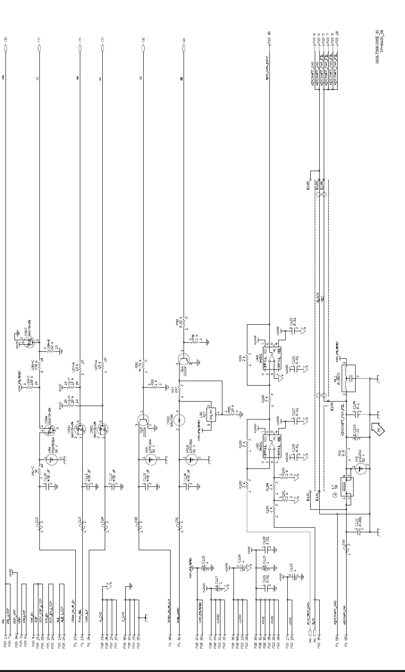
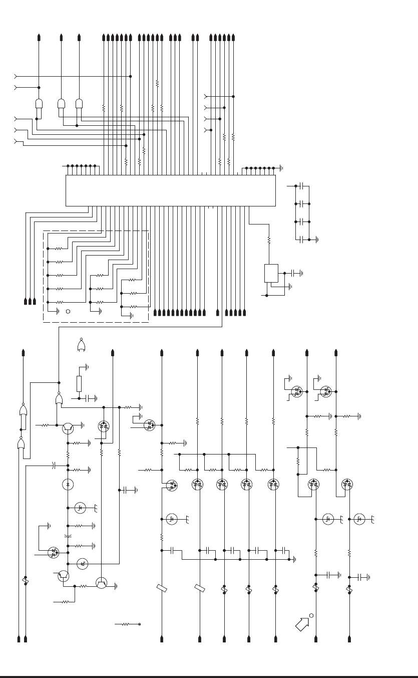
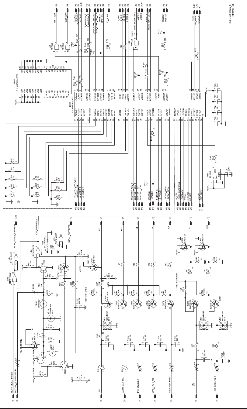
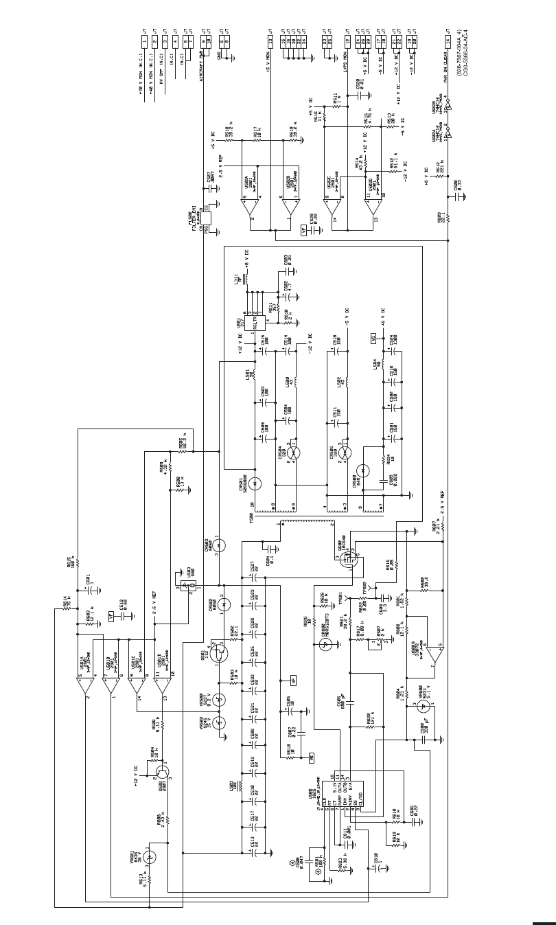
Video Processor Circuit Card A6 (CPN 687-0726-006) and Video Processor Circuit Card
Assembly A6 (CPN 983-8019-001), Schematic Diagram
Figure 2028 (Sheet 5 of 8)/GRAPHIC 34-50-96-99B-063-A01
34-50-96 Page 2213/2214
May 18/06
ROCKWELL COLLINS
COMPONENT MAINTENANCE MANUAL with IPL
TDR-94, PART NO 622-9352
(828-7566-006C_6)
TPH6410_06
+28V_FILTERED
+28V_FILTERED
AA
A A
A
A
+12VDC
+12VDC +12VDC
+12VDC
-12VDC
-12VDC
BAS70-04
BAS70-04
BAS70-04
BAS70-04
+5VDC
+5VDC +5VDC
470 PF
470 PF
470 PF
470 PF
470 PF
0.001 22
+
0.1
50
4.75 K
237
3.92 K
2 K
2 K
2 K
2 K
2 K
2 K2 K
2 K
10 K 10 K
100 K
62 K
270 K
10 K
10 K
317
RGLTR
36
P6SMB36A
36 V
1SMC36A
36 V
1SMC36A
36 V
1N6293
82 V
+28V_FILTERED
BAW78D
0.0
2222A
1 K
2222A
0.0022
AD817
-
+
NULL
NULL -VS
+VS
NC
A
AD817
-
+
NULL
NULL -VS
+VS
NC
0.010.01
0.010.01
1 K
10 K
AIRCRAFT_GND
AIRCRAFT_PWR_FIL
3
1
2
R95
DD
STDBY_ON_XF_OUT
1
2
R93
EE
AIRCRAFT_GND
(8)
(8)
(8)
(8)
(8)
1
2
C128 1
2
C127 1
2
C126 1
2
C125
2
3
1
8
6
7
4
5
U39
TEST_DATA_INPUT
5
4
7
6
8
1
3
2
U40
1
2
3
FL1
2
1
3
Q10
1
2
R94
2
1
3
Q11
12
R92
23
CR69
AIRCRAFT_PWR_FIL
12
Z31
1
2
VR6
12
Z30
FAIL_WARN
AIRCRAFT_PWR
12
Z58
12
Z15
12
Z14
12
Z13
1
2
VR18
1
2
VR5
1
2
VR4
710
U41
3
1
2
U38
215
U37
116
U37
314
U36
2
15
U34
3
14
U33
16
14
U1
16
13
U1
12
R106
12
R105
12
R104
1
2
R103
12
R102
1
2
R101
12
R100
12
R99
12
R98
12
R97
12
R96
1
23
4
L7
1
2
C124
1
2
C123
1
2
C122
1
2
C114
1
2
C113
1
2
C112
1
2
C111
1
2
C110
TLP6
TCAS_SEL
STDBY_ON_XF_IN
RCVR_TEST_DATA
CONT_ALT
CC
BB
AA
21
3
CR67
2
13
CR65
2
13
CR66
21
3
CR64
E100
E102
E103
E104
E105
E101
(8)
(5,8)
(5)
(8)
(8)
(7)
(7)
(7)
(3)
(3)
(8)
(8)
A
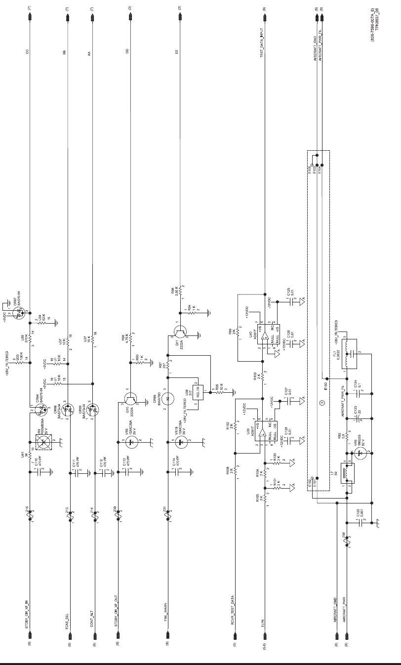
Video Processor Circuit Card A6 (CPN 687-0726-006) and Video Processor Circuit Card
Assembly A6 (CPN 983-8019-001), Schematic Diagram
Figure 2028 (Sheet 6 of 8)/GRAPHIC 34-50-96-99B-063-A01
34-50-96 Page 2215/2216
May 18/06
ROCKWELL COLLINS
COMPONENT MAINTENANCE MANUAL with IPL
TDR-94, PART NO 622-9352
(828-7566-006C_7)
TPH6410_07
+28V_FILTERED
+28V_FILTERED
BAS70-04
BAS70-04
BAS70-04
BAS70-04
BAS70-04
BAS70-04
BAS70-04
BAS70-04
BAS70-04
BAS70-04
BAS70-04
BAS70-04
BAS70-04
BAS70-04
BAS70-04
BAS70-04
BAS70-04
BAS70-04
BAS70-04
BAS70-04
+5VDC
+5VDC
+5VDC
+5VDC
+5VDC
+5VDC
+5VDC
470 PF
470 PF
470 PF
470 PF
470 PF
470 PF
470 PF
470 PF
470 PF
470 PF
470 PF
0.01
0.01
100 K
100 K
100 K
100 K
62 K
62 K
62 K
62 K
62 K
36
36
36
36
36
270 K
270 K
270 K
270 K
270 K
36
36
36
36
36
36
100 K
100 K
100 K
100 K
100 K
100 K
100 K
100 K
62 K
62 K
62 K
62 K
62 K
62 K
270 K
270 K
270 K
270 K
270 K
270 K
P6SMB36A
36 V
P6SMB36A
36 V
P6SMB36A
36 V
P6SMB36A
36 V
P6SMB36A
36 V
P6SMB36A
36 V
P6SMB36A
36 V
P6SMB36A
36 V
P6SMB36A
36 V
P6SMB36A
36 V
P6SMB36A
36 V
100 K
BAS70-04
BAS70-04
SN74ABT2244ADB
OEB
OEA
VCC
GND
OA0
OA1
OA2
OA3
OB0
OB1
OB2
OB3
DB3
DB2
DB1
DB0
DA3
DA2
DA1
DA0
SN74ABT2244ADB
OEBOEA
VCC
GND
OA0
OA1
OA2
OA3
OB0
OB1
OB2
OB3DB3
DB2
DB1
DB0
DA3
DA2
DA1
DA0
GILLHAM_C
2
4
6
8
11
13
15
17
119
3
5
7
9
12
14
16
18
20
10
U45
12
Z1
GILLHAM_ALT_B4
12
Z2
GILLHAM_ALT_B2
12
Z3
GILLHAM_ALT_B1
2
4
6
8
11
13
15
17
119
3
5
7
9
12
14
16
18
20
10
U44
DB[0:7]
DB7
DB6
DB5
DB4
DB3
DB2
DB1
DB0
DB7
DB6
DB5
DB4
DB3
DB2
DB1
DB0
12
Z9
12
Z10
12
Z11
GILLHAM_ALT_C1
21
3
CR80
21
3
CR77
12
Z8
GILLHAM_ALT_D4
12
Z7
GILLHAM_ALT_A1
12
Z6
GILLHAM_ALT_A2
12
Z5
611
U33
12
Z4
12
VR17
12
VR16
12
VR15
1
2
VR14
1
2
VR13
1
2
VR12
1
2
VR11
1
2
VR10
1
2
VR9
1
2
VR8
1
2
VR7
611
U46
512
U46
413
U46
314
U46
215
U46
116
U46
611
U43
512
U43
413
U43
314
U43
215
U43
116
U43
8
9
U42
710
U42
611
U42
512
U42
413
U42
314
U42
215
U42
116
U42
611
U41
512
U41
413
U41
314
U41
215
U41
116
U41
89
U36
710
U36
611
U36
512
U36
413
U36
89
U35
710
U35
611
U35
512
U35
413
U35
89
U34
710
U34
611
U34
512
U34
413
U34
89
U33
710
U33
512
U33
413
U33
1
2
C141
1
2
C140
12
C139
1
2
C138
12
C137
1
2
C136
1
2
C135
1
2
C134
1
2
C133
1
2
C132
1
2
C131
1
2
C130
1
2
C129
GILLHAM_BAD
GILLHAM_ALT_D2
GILLHAM_ALT_C4
GILLHAM_ALT_C2
GILLHAM_ALT_A4
GG
FF
CC
BB
AA
21
3
CR90
21
3
CR89
21
3
CR88
21
3
CR87
21
3
CR86
21
3
CR85
21
3
CR84
21
3
CR83
21
3
CR82
21
3
CR81
21
3
CR79
21
3
CR78
21
3
CR76
21
3
CR75
21
3
CR74
21
3
CR73
21
3
CR72
21
3
CR71
21
3
CR70
21
3
CR68
(1,3)
(6)
(6)
(6)
(5)
(5)
(8)
(8)
(8)
(8)
(8)
(8)
(8)
(8)
(8)
(8)
(8)
(8)
(8)
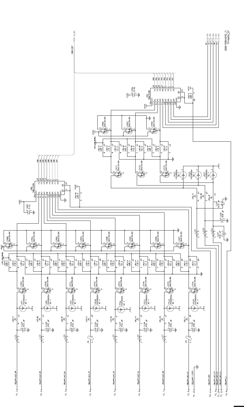
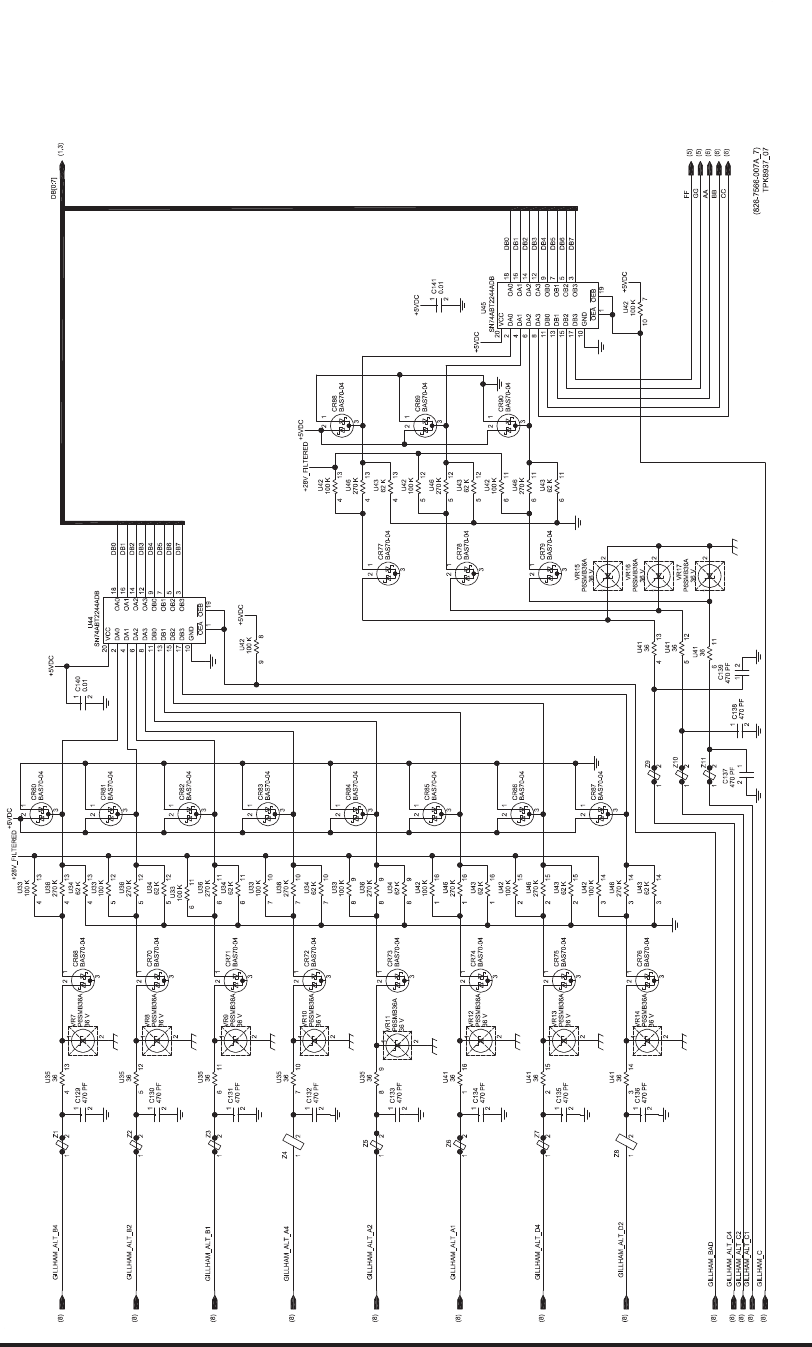
Video Processor Circuit Card A6 (CPN 687-0726-006) and Video Processor Circuit Card
Assembly A6 (CPN 983-8019-001), Schematic Diagram
Figure 2028 (Sheet 7 of 8)/GRAPHIC 34-50-96-99B-063-A01
34-50-96 Page 2217/2218
May 18/06
ROCKWELL COLLINS
COMPONENT MAINTENANCE MANUAL with IPL
TDR-94, PART NO 622-9352
(828-7566-006C_8)
TPH6410_08
+5VDC
33.2
33.2
33.2
33.2
33.2
-12VDC
+5VDC
A
A
1
+
0.01 1
+
0.01
1
+
1
+
+12VDC
-12VDC
-5VDC
+12VDC
+5VDC
+5VDC
+12VDC
+5VDC
+5VDC
+12VDC
-12VDC
-5VDC
+28V_FILTERED
+5VDC
A
33.2
33.2
33.2
33.2
33.2
33.2
33.2
33.2
33.2
33.2
33.2
33.2
33.2
33.2
33.2
1
+
A
A
A
P25
P22
P22
P25
P25
P25
P25
P25
P25
P25
P20
P20
P20
P20
P20 P3
P3
P3
P3
P3
24
P3
P3
P3
RESERVED_P3_23
MODE_S_COMM
WRH_LOOP
ROM_EN_LOOP
ROM_RDF_LOOP
GILLHAM_COMM
23
RESERVED_P3_19
RESERVED_P3_17
21
19
17
RESERVED_P3_21
RESERVED_P3_24
P3 P3
RESERVED_P3_22
RESERVED_P3_20
RESERVED_P3_18
22
20
18
14 RESERVED_10MHZ
8
14
P20P20 RESERVED_BVT
16
20
22 RESERVED_P20_22
RESERVED_P20_20
RESERVED_P20_16
RESERVED_TVT
RESERVED_P20_11
13
11
RESERVED_P20_34
34
10
P25
P25 6
5P25
SPARE_P25_5
SPARE_P25_9 9 P25
SPARE_P25_11 11
SPARE_P25_17 17
45
35
RESERVED_P25_45
RESERVED_P25_35
RESERVED_P25_10
RESERVED_P25_6
34
36
46 RESERVED_P25_46
RESERVED_P25_36
RESERVED_P25_34
P22
34
RESERVED_P34
30
RESERVED_P30 32
RESERVED_P32
22
SUPPRESSION_SHIELD
RESERVED_P25_22
ROM_VPP
ROM_VCC
ALE_LOOP
SPARE_P3_8
WRL_LOOP
TYPE_2
5
1
2
C116
WRL
RDF_IN
RDF_IN
(5)
(5)
(3)
(4)
12
R129
12
R116
21
R121
GILLHAM_BAD
21
R128
12
R127
21
R119
SELFTEST_INH-F
DB7
DB0
DB[0:7]
DB5
DB3
DB1
DB6
DB4
DB2
12
R125
21
R124
ALE
VP_WR_D
VP_WR_E
12
R112
2
1
R123
12
R122 VP_RD_D
TYPE_READ_F
2
1
R120
TOP_LOW_PWR
12
R107
SADD_17-24_EN
SADD_1-8_EN
21
R109
12
R108
BOT_LOW_PWR
MOD_TEMP
7P26
5P26
3P26
1P26
AIRCRAFT_PWR_FIL
AIRCRAFT_GND
AIRCRAFT_GND EX_SQUIT_DISABLE_F
A8
A[0:9]
A7
A5
A3
A1
A9
A6
A4
A2
A0
RCVR_TEST_ENABLE
RCVR_TEST_ENABLE
AIRCRAFT_GND
+35V_MON
ROM_EN
WRH
RST
RST
MOD_DOWN_LINK
32 P1
58 P1 57 P1
53 P1
49 P1
45 P1
41 P1
37 P1
33 P1
29
P1
25 P1
21 P1
17 P1
13 P1
54 P1
50 P1
46 P1
42 P1
38 P1
34 P1
30 P1
26 P1
22 P1
18 P1
14 P1
15 P1
19 P1
23 P1
27 P1
31 P1
35 P1
39 P1
43 P1
47 P1
51 P1
55 P1
59 P1
60 P1
56 P1
52 P1
48 P1
44 P1
40 P1
36 P1
28 P1
24 P1
20 P1
16 P1
12 P1 11 P1 10 P1 9P1
8P1 7P1 6P1 5P1
4P1 3P1 2P1
AIRCRAFT_PWR AIS/ADS_LO/HI_SEL
MODE_S_ADDR_B24 MODE_S_ADDR_B23 MODE_S_ADDR_B22 MODE_S_ADDR_B21
MODE_S_ADDR_B20 MODE_S_ADDR_B19 MODE_S_ADDR_B18 MODE_S_ADDR_B17
MODE_S_ADDR_B16 MODE_S_ADDR_B15 MODE_S_ADDR_B14 MODE_S_ADDR_B13
MODE_S_ADDR_B12 MODE_S_ADDR_B11 MODE_S_ADDR_B10 MODE_S_ADDR_B9
MODE_S_ADDR_B8 MODE_S_ADDR_B7 MODE_S_ADDR_B6 MODE_S_ADDR_B5
MODE_S_ADDR_B4 MODE_S_ADDR_B3 MODE_S_ADDR_B2 MODE_S_ADDR_B1
FAIL_WARN STDBY_ON_XF_OUT MUTUAL_SUPPRESSION
AUTO_/ALT_SEL AIR_GROUND_2
FMS/IRS_LO/HI_SEL TYPE_3 TYPE_1
TYPE_0 GPS_LO/HI_SEL IRS_ENABLE-F
SPI STDBY_ON_XF_IN CONT_ALT TCAS_SEL
GILLHAM_ALT_C1 GILLHAM_ALT_C2 GILLHAM_ALT_C4
GILLHAM_ALT_D2 GILLHAM_ALT_D4 GILLHAM_ALT_A1 GILLHAM_ALT_A2
GILLHAM_ALT_A4 GILLHAM_ALT_B1 GILLHAM_ALT_B2 GILLHAM_ALT_B4
DPSK_CHNL_SEL_BOT
1P1
TLP6
DPSK_DATA
DPSK_CHNL_SEL_TOP
TOP_BOT_TEST_SEL
TEST_DATA_INPUT
BOT_VIDEO
TOP_VIDEO
RCVR_VIDEO_SUPPRESS
+5_V_MON
P/S_MON
DPSK_EN
HV_OFF
+70V_MON
1
2
C117
1
2C118
1
2
C120
1
2
C115
1
2
C121
1
2C119
37 P22
13 P22
21 P22
17 P22
1P22
5P22
9P22
25 P22
29 P22
33 P22
8P22
7P22
6P22
4P22
12 P22
16 P22
20 P22
24 P22
28 P22
36 P22
40 P22
39 P22
35 P22
31 P22
27 P22
26 P22
23 P22
19 P22
15 P22
11 P22
3P22
2P22
10 P22
14 P22
18 P22
22 P22
38 P22
2_MHZ
28
P25
ATCRBS_LMT
DUAL_PORT_EN
HV_OFF
XMIT_TOP
XMIT_BOT ATCRBS
33 P25
37 P25
39 P25
41 P25
43 P25
47 P25 48
P25
44
P25
42
P25
40
P25
38
P25
32
P25
25 P25
27 P25
29 P25
31 P25
23 P25
21 P25
19 P25
30
P25
26
P25
24
P25
20
P25
18
P25
16
P25
14
P25
12
P25
8
P25
4
P25
2
P25
15 P25
13 P25
7P25
3P25
1P25
2
P3
4
P3
6
P3
10
P3
12
P3
16
P3
15 P3
13 P3
11 P3
9P3
7P3
5P3
3P3
1P3
12
P20
18
P20
24
P20
26
P20
28
P20
30
P20
32
P20
36
P20
38
P20
15 P20
17 P20
19 P20
21 P20
23 P20
25 P20
29 P20
31 P20
27 P20
33 P20
35 P20
37 P20
40
P20
39 P20
1_MHZ
MODES
LOOPBACK
MP_RST
P1/3/4
AIRCRAFT_PWR_FIL
AIRCRAFT_PWR_FIL
AIRCRAFT_PWR_FIL
A_PRA
A_PRB
A_SDO
A_MODE
A_SDI
A_DCLK
2
P26
4
P26
6
P26
8
P26
12
Z25
12
R110
21
R111
2
1
R113 12
R114 2
1
R115
VP_RD_C
SADD_9-16_EN
GILLHAM_C
(2)
(3)
(4,5)
(5)
(3)
(5)
(5)
(6)
(5)
(6)
(6)
(6)
(6)
(5)
(2,5)
(3)
(5,6)
(5)
(6)
(6)
(1)
(6)
(5)
(7)
(7)
(7)
(1)
(1)
(1)
(1)
(1)
(1)
(5)
(1)
(1)
(6)
(1)
(1)
(1)
(1)
(6)
(1)
(1)
(5)
(6)
(5)
(7)
(7)
(7)
(1)
(1)
(1)
(1)
(1)
(1)
(6)
(1)
(1)
(5)
(6)
(5)
(7)
(7)
(7)
(1)
(1)
(1)
(1)
(1)
(1)
(6)
(5)
(1)
(1)
(5)
(7)
(7)
(3)
(3)
(3)
(1)
(1)
(5)
(5)
(7)
(5)
(3)
(3)
(3)
(3)
(3)
(5)
(3)
(3)
(2)
(2)
(5)
(1)
(1)
(3)
(3)
(7)
(3)
(4)
(4)
(4)
(4)
(4)
(4,5)
5
5
5
6
B
A
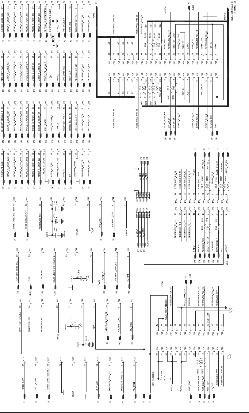
Video Processor Circuit Card A6 (CPN 687-0726-006) and Video Processor Circuit Card
Assembly A6 (CPN 983-8019-001), Schematic Diagram
Figure 2028 (Sheet 8 of 8)/GRAPHIC 34-50-96-99B-063-A01
34-50-96 Page 2219/2220
May 18/06

ROCKWELL COLLINS
COMPONENT MAINTENANCE MANUAL with IPL
TDR-94, PART NO 622-9352
MAINTENANCE AID/SCHEMATIC CHANGES
REVISION
IDENT
(SHEET)
DESCRIPTION OF REVISION AND CAUSE FOR CHANGE SERVICE
BULLETIN
EFFECTIVITY
MARKING
(This sheet will contain maintenance aid and schematic
revision data.)
Video Processor Circuit Card A6 (CPN 687-0726-007), Maintenance Aid and Schematic Changes
Table 2015.1/Table 34-50-96-99A-045-A01
34-50-96 Page 2220.1/2220.2
May 20/10
ROCKWELL COLLINS
COMPONENT MAINTENANCE MANUAL with IPL
TDR-94, PART NO 622-9352
Video Processor Circuit Card A6 (CPN 687-0726-007), Maintenance Aid Diagram
Figure 2028.1 (Sheet 1 of 4)/GRAPHIC 34-50-96-99B-100-A01
34-50-96 Page 2220.3/2220.4
May 20/10
ROCKWELL COLLINS
COMPONENT MAINTENANCE MANUAL with IPL
TDR-94, PART NO 622-9352
Video Processor Circuit Card A6 (CPN 687-0726-007), Maintenance Aid Diagram
Figure 2028.1 (Sheet 2 of 4)/GRAPHIC 34-50-96-99B-100-A01
34-50-96 Page 2220.5/2220.6
May 20/10
ROCKWELL COLLINS
COMPONENT MAINTENANCE MANUAL with IPL
TDR-94, PART NO 622-9352
Video Processor Circuit Card A6 (CPN 687-0726-007), Maintenance Aid Diagram
Figure 2028.1 (Sheet 3 of 4)/GRAPHIC 34-50-96-99B-100-A01
34-50-96 Page 2220.7/2220.8
May 20/10
ROCKWELL COLLINS
COMPONENT MAINTENANCE MANUAL with IPL
TDR-94, PART NO 622-9352
Video Processor Circuit Card A6 (CPN 687-0726-007), Maintenance Aid Diagram
Figure 2028.1 (Sheet 4 of 4)/GRAPHIC 34-50-96-99B-100-A01
34-50-96 Page 2220.9/2220.10
May 20/10
ROCKWELL COLLINS
COMPONENT MAINTENANCE MANUAL with IPL
TDR-94, PART NO 622-9352
Video Processor Circuit Card A6 (CPN 687-0726-007), Schematic Diagram
Figure 2028.2 (Sheet 1 of 8)/GRAPHIC 34-50-96-99B-101-A01
34-50-96
Page 2220.11/
2220.12
May 20/10
ROCKWELL COLLINS
COMPONENT MAINTENANCE MANUAL with IPL
TDR-94, PART NO 622-9352
Video Processor Circuit Card A6 (CPN 687-0726-007), Schematic Diagram
Figure 2028.2 (Sheet 2 of 8)/GRAPHIC 34-50-96-99B-101-A01
34-50-96
Page 2220.13/
2220.14
May 20/10
ROCKWELL COLLINS
COMPONENT MAINTENANCE MANUAL with IPL
TDR-94, PART NO 622-9352
Video Processor Circuit Card A6 (CPN 687-0726-007), Schematic Diagram
Figure 2028.2 (Sheet 3 of 8)/GRAPHIC 34-50-96-99B-101-A01
34-50-96
Page 2220.15/
2220.16
May 20/10
ROCKWELL COLLINS
COMPONENT MAINTENANCE MANUAL with IPL
TDR-94, PART NO 622-9352
Video Processor Circuit Card A6 (CPN 687-0726-007), Schematic Diagram
Figure 2028.2 (Sheet 4 of 8)/GRAPHIC 34-50-96-99B-101-A01
34-50-96
Page 2220.17/
2220.18
May 20/10
ROCKWELL COLLINS
COMPONENT MAINTENANCE MANUAL with IPL
TDR-94, PART NO 622-9352
Video Processor Circuit Card A6 (CPN 687-0726-007), Schematic Diagram
Figure 2028.2 (Sheet 5 of 8)/GRAPHIC 34-50-96-99B-101-A01
34-50-96
Page 2220.19/
2220.20
May 20/10
ROCKWELL COLLINS
COMPONENT MAINTENANCE MANUAL with IPL
TDR-94, PART NO 622-9352
Video Processor Circuit Card A6 (CPN 687-0726-007), Schematic Diagram
Figure 2028.2 (Sheet 6 of 8)/GRAPHIC 34-50-96-99B-101-A01
34-50-96
Page 2220.21/
2220.22
May 20/10
ROCKWELL COLLINS
COMPONENT MAINTENANCE MANUAL with IPL
TDR-94, PART NO 622-9352
Video Processor Circuit Card A6 (CPN 687-0726-007), Schematic Diagram
Figure 2028.2 (Sheet 7 of 8)/GRAPHIC 34-50-96-99B-101-A01
34-50-96
Page 2220.23/
2220.24
May 20/10
ROCKWELL COLLINS
COMPONENT MAINTENANCE MANUAL with IPL
TDR-94, PART NO 622-9352
Video Processor Circuit Card A6 (CPN 687-0726-007), Schematic Diagram
Figure 2028.2 (Sheet 8 of 8)/GRAPHIC 34-50-96-99B-101-A01
34-50-96
Page 2220.25/
2220.26
May 20/10

ROCKWELL COLLINS
COMPONENT MAINTENANCE MANUAL with IPL
TDR-94, PART NO 622-9352
MAINTENANCE AID/SCHEMATIC CHANGES
REVISION
IDENT
(SHEET)
DESCRIPTION OF REVISION AND CAUSE FOR CHANGE SERVICE
BULLETIN
EFFECTIVITY
MARKING
A (3) Deleted R435; it is not required. REV A
N/A Internal documentation change only. REV B
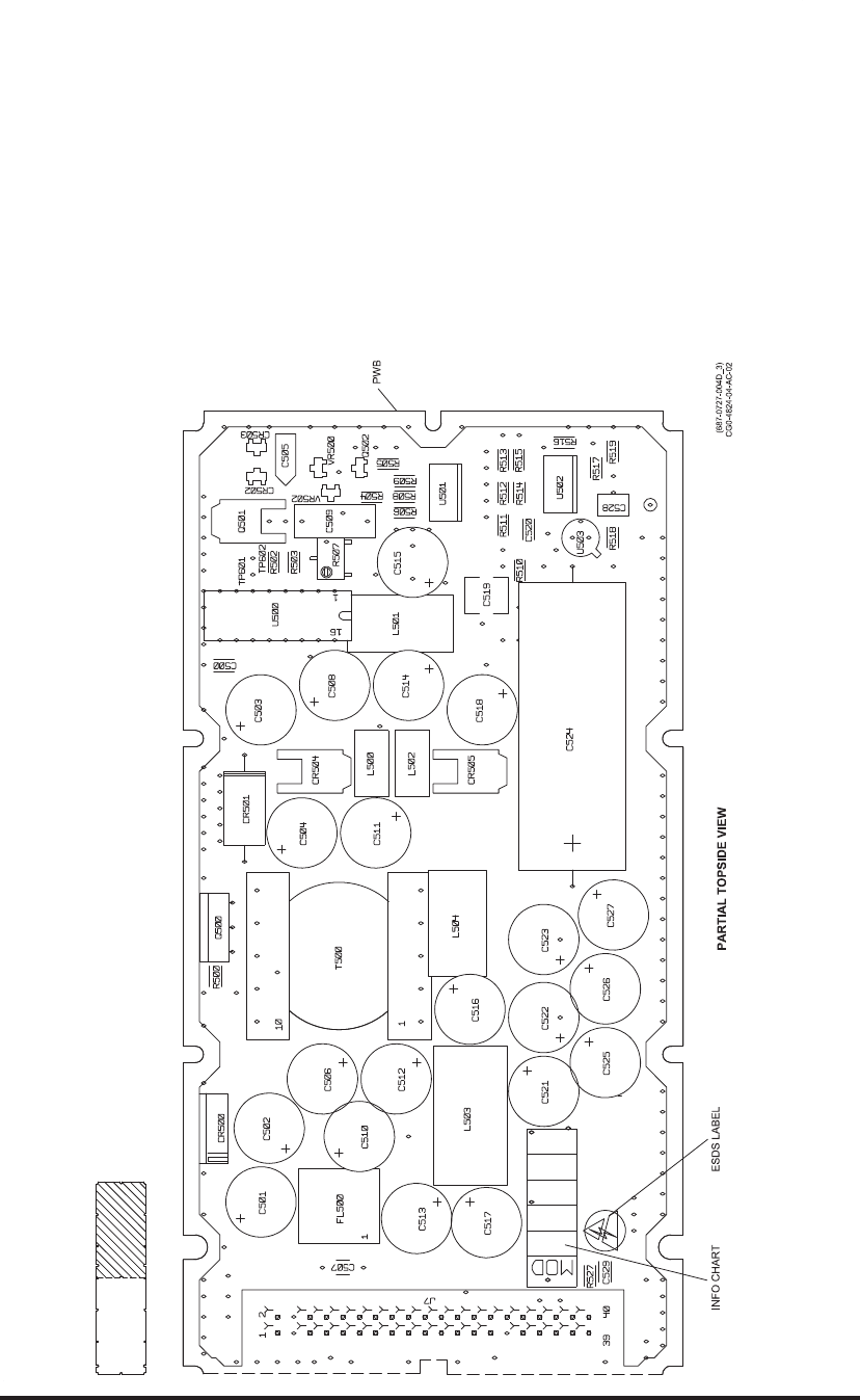
C (3) Changed R430 from 357വto a test selected value to account
for input trigger level differences in U301 at 70°C. Also added
info chart to circuit card.
REV C
N/A Changed ESDS label to the circular style. REV D
IF Receiver, DPSK Detector, and LVPS Circuit Card A7 (CPN 687-0727-004), Maintenance Aid and
Schematic Changes
Table 2016/Table 34-50-96-99A-027-A01
34-50-96 Page 2221/2222
May 18/06
ROCKWELL COLLINS
COMPONENT MAINTENANCE MANUAL with IPL
TDR-94, PART NO 622-9352
IF Receiver, DPSK Detector, and LVPS Circuit Card A7 (CPN 687-0727-
004), Maintenance Aid Diagram
Figure 2029 (Sheet 1 of 4)/GRAPHIC 34-50-96-99B-064-A01
34-50-96 Page 2223/2224
May 18/06
ROCKWELL COLLINS
COMPONENT MAINTENANCE MANUAL with IPL
TDR-94, PART NO 622-9352
IF Receiver, DPSK Detector, and LVPS Circuit Card A7 (CPN 687-0727-
004), Maintenance Aid Diagram
Figure 2029 (Sheet 2 of 4)/GRAPHIC 34-50-96-99B-064-A01
34-50-96 Page 2225/2226
May 18/06
ROCKWELL COLLINS
COMPONENT MAINTENANCE MANUAL with IPL
TDR-94, PART NO 622-9352
IF Receiver, DPSK Detector, and LVPS Circuit Card A7 (CPN 687-0727-
004), Maintenance Aid Diagram
Figure 2029 (Sheet 3 of 4)/GRAPHIC 34-50-96-99B-064-A01
34-50-96 Page 2227/2228
May 18/06
ROCKWELL COLLINS
COMPONENT MAINTENANCE MANUAL with IPL
TDR-94, PART NO 622-9352
IF Receiver, DPSK Detector, and LVPS Circuit Card A7 (CPN 687-0727-
004), Maintenance Aid Diagram
Figure 2029 (Sheet 4 of 4)/GRAPHIC 34-50-96-99B-064-A01
34-50-96 Page 2229/2230
May 18/06
ROCKWELL COLLINS
COMPONENT MAINTENANCE MANUAL with IPL
TDR-94, PART NO 622-9352
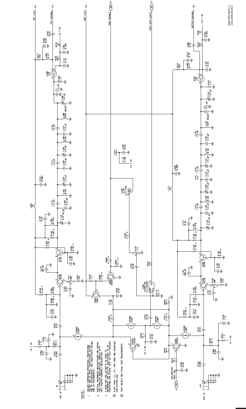
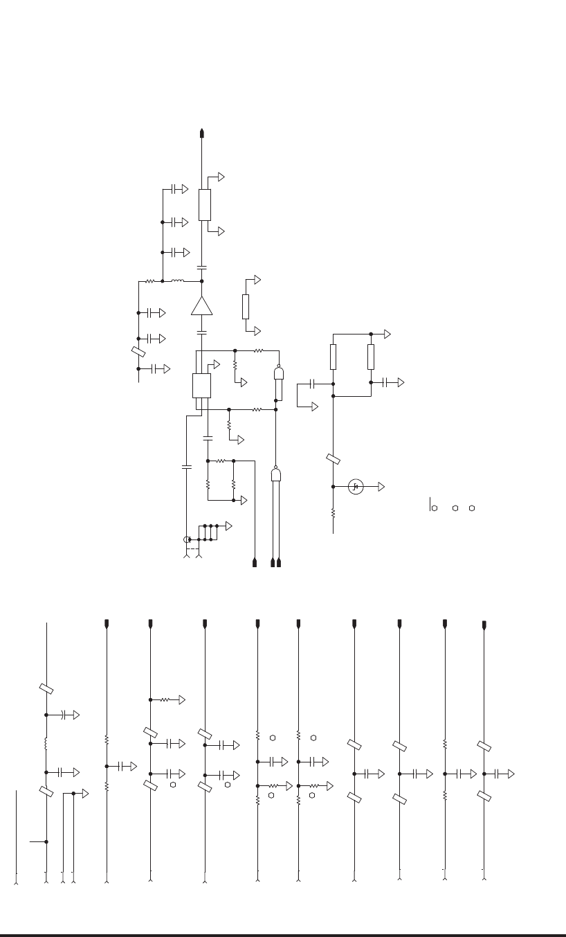
IF Receiver, DPSK Detector, and LVPS Circuit Card A7 (CPN 687-0727-004), Schematic Diagram
Figure 2030 (Sheet 1 of 4)/GRAPHIC 34-50-96-99B-065-A01
34-50-96 Page 2231/2232
May 18/06
ROCKWELL COLLINS
COMPONENT MAINTENANCE MANUAL with IPL
TDR-94, PART NO 622-9352
IF Receiver, DPSK Detector, and LVPS Circuit Card A7 (CPN 687-0727-004), Schematic Diagram
Figure 2030 (Sheet 2 of 4)/GRAPHIC 34-50-96-99B-065-A01
34-50-96 Page 2233/2234
May 18/06
ROCKWELL COLLINS
COMPONENT MAINTENANCE MANUAL with IPL
TDR-94, PART NO 622-9352
IF Receiver, DPSK Detector, and LVPS Circuit Card A7 (CPN 687-0727-004), Schematic Diagram
Figure 2030 (Sheet 3 of 4)/GRAPHIC 34-50-96-99B-065-A01
34-50-96 Page 2235/2236
May 18/06
ROCKWELL COLLINS
COMPONENT MAINTENANCE MANUAL with IPL
TDR-94, PART NO 622-9352
IF Receiver, DPSK Detector, and LVPS Circuit Card A7 (CPN 687-0727-004), Schematic Diagram
Figure 2030 (Sheet 4 of 4)/GRAPHIC 34-50-96-99B-065-A01
34-50-96 Page 2237/2238
May 18/06

ROCKWELL COLLINS
COMPONENT MAINTENANCE MANUAL with IPL
TDR-94, PART NO 622-9352
MAINTENANCE AID/SCHEMATIC CHANGES
REVISION
IDENT
(SHEET)
DESCRIPTION OF REVISION AND CAUSE FOR CHANGE SERVICE
BULLETIN
EFFECTIVITY
MARKING
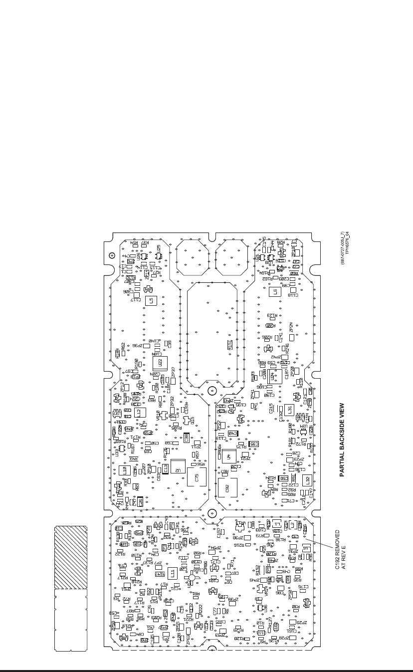
N/A Implemented circuit card into production. 25 REV D
N/A Removed C192. This component should not have been
populated on the circuit card.
REV E
N/A Internal documentation changes only. REV F
N/A FL3 and FL4 changed from CPN 241-5066-030 to CPN
241-5066-040. There are no value changes. CPN
241-5066-030 may be used as an alternate part if necessary.
REV G
H (2) Changed C201 from 0.001 μF 10 pF to reduce the amount of
60 MHz signal being coupled into RF mixer U103. This change
lowers the adjustment range of the self-test video pot, R155.
REV H
N/A Internal documentation changes only. REV J
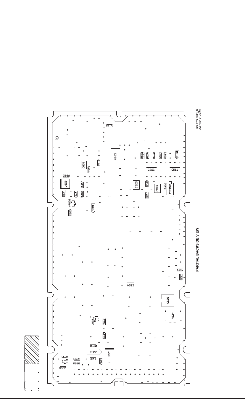
J1 (6) Revised L18 from 22nH to a test select. Variations observed
in the VCO IC U20 and inductor L19 caused excessive fallout.
REV L
J2 (7) Revised C610 from 1 μF to 0.1μF to address start-up
problems.
28 REV M
IF Receiver, DPSK Detector, and LVPS Circuit Card A7 (CPN 687-0727-005), Maintenance Aid and
Schematic Changes
Table 2017/Table 34-50-96-99A-028-A01
34-50-96 Page 2239/2240
May 20/10
ROCKWELL COLLINS
COMPONENT MAINTENANCE MANUAL with IPL
TDR-94, PART NO 622-9352
IF Receiver, DPSK Detector, and LVPS Circuit Card A7 (CPN 687-0727-
005), Maintenance Aid Diagram
Figure 2031 (Sheet 1 of 4)/GRAPHIC 34-50-96-99B-066-A01
34-50-96 Page 2241/2242
May 18/06
ROCKWELL COLLINS
COMPONENT MAINTENANCE MANUAL with IPL
TDR-94, PART NO 622-9352
IF Receiver, DPSK Detector, and LVPS Circuit Card A7 (CPN 687-0727-
005), Maintenance Aid Diagram
Figure 2031 (Sheet 2 of 4)/GRAPHIC 34-50-96-99B-066-A01
34-50-96 Page 2243/2244
May 18/06
ROCKWELL COLLINS
COMPONENT MAINTENANCE MANUAL with IPL
TDR-94, PART NO 622-9352
IF Receiver, DPSK Detector, and LVPS Circuit Card A7 (CPN 687-0727-
005), Maintenance Aid Diagram
Figure 2031 (Sheet 3 of 4)/GRAPHIC 34-50-96-99B-066-A01
34-50-96 Page 2245/2246
May 18/06
ROCKWELL COLLINS
COMPONENT MAINTENANCE MANUAL with IPL
TDR-94, PART NO 622-9352
IF Receiver, DPSK Detector, and LVPS Circuit Card A7 (CPN 687-0727-
005), Maintenance Aid Diagram
Figure 2031 (Sheet 4 of 4)/GRAPHIC 34-50-96-99B-066-A01
34-50-96 Page 2247/2248
May 18/06
ROCKWELL COLLINS
COMPONENT MAINTENANCE MANUAL with IPL
TDR-94, PART NO 622-9352
(828-7567-005D_1)
TPH6585_01
AG201-86
GND GND
AG201-86
200
A1
470 PF
470 PF
470 PF
470 PF
422
A1
+12VDC
100 PF
0.1
0.1
17.4
294
6800 PF
AS214-92
GND
J2
V2
J1
J3
V1
3
3
A1
A1
15
A1
56 PF
56 PF
0
0
470 PF
A1 A1
A1
INSTALLED ON FINAL ASSEMBLY.
SHOWN FOR REFERENCE ONLY AND IS NOT
3
A1
UNIT AND/OR ASSEMBLY DESIGNATION.
FOR COMPLETE DESIGNATION, PREFIX WITH
PARTIAL REFERENCE DESIGNATIONS ARE SHOWN;
ARE IN MICROHENRYS.
ARE IN MICROFARADS, AND INDUCTANCE VALUES
VALUES ARE IN OHMS, CAPACITANCE VALUES
UNLESS OTHERWISE SPECIFIED, RESISTANCE1
2
NOTES:
A1
A1
A1
1.5
A1
A1
6800 PF 6800 PF
A1
49.9
470 PF
A1
+8VDC
A1
47 PF
A1
A1
0
470 PF
49.9
0
3
3
1 K
1 K
A1
A1
A1
49.9 49.9
0.1
MMBZ5231B
5.1 V
A1
NC7SZ00P5
GND
VCC
NC7SZ00P5
GND
VCC
0.1
A1
A1
A1
NC7SZ00P5
NC7SZ00P5
60 MHZ
IN OUT
GND GND
3
+8VDC
0.01
6800 PF
A1
A1
A1
6800 PF
A1
294
3470 PF
1
+
0.010.1
A1
-12VDC
-12VDC_IF
A1
1 K
A1
1 K
A1
1 K
1 K
A1
1 K
A1
HIGH = TOP
TOP_IF
Gp=20dB
I=20MA
Vd=4V
1
2
R82
(3)
1
2
R37
12
R55
1
2
R12
12
R54
TOP/BOT_TST_SEL_IF
1
2
C17
2
1C1
1
2C159
21
ZP35
1
2
C155
SELF_TEST_SIG
1
2
3
4
5
J9
(2)
12
R49
DPSK_ENABLE_IF
(5)
(2)
21
ZP8
11
J7
36
J7
12
C56
(4)
(3)
(5)
1
2
C306
1
2
C4
39
J7
12
34
FL3
DPSK_TOP_SEL_IF
(3,4)
(5)
TOP/BOT_TST_SEL_IF
TEST_ENABLE_IF 1
24
U25
4
2
1
U26
(2)
2
1C115
35
U26
53
U25
3
1
VR4
12
ZP14
1
2
C114
(2)
38
J7
21
R10
12
R9
12
ZP30
2
1
ZP17
12
ZP16
2
1
ZP15
19
J7
21
J7
23
J7
25
J7
33
J7
31
J7
40
J7
27
J7
37
J7
12
ZP6
1
2
R173
1
2
R174
21
R128
12
R126
1
2
C160
12
R131
1
2
C117
12
ZP2
21
ZP29
2
1C161
12
ZP27
2
1
ZP26
21
R127
12
C32
21
C33
1
2
L5
12
ZP28
TOP_VIDEO_IF
BOT_VIDEO_IF
FROM_FILTER_1
DPSK_DATA_IF
1
2
C156
12
R129
12
R130
1
2
C164
1
2
C163
12
L15
(2)
(2)
53
1
46
2
U29
TEST_DATA_IF
TEST_ENABLE_IF
12
C55
12
ZP1
12
R50
1
2
R148
1
2
C15
1
2
C307
1
2
C111
12
R27
1
2
C105
1
2
C162
1
2
C107
1
2
C106
RCVR_VIDEO_SUPP_IF 1
2
R132
13
U42
24
U42
IF Receiver, DPSK Detector, and LVPS Circuit Card A7 (CPN 687-0727-005), Schematic Diagram
Figure 2032 (Sheet 1 of 7)/GRAPHIC 34-50-96-99B-067-A01
34-50-96 Page 2249/2250
May 18/06
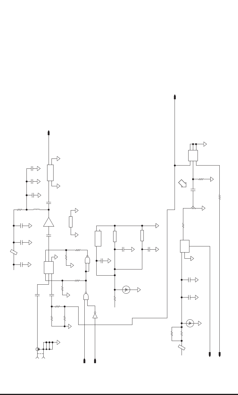
ROCKWELL COLLINS
COMPONENT MAINTENANCE MANUAL with IPL
TDR-94, PART NO 622-9352
(828-7567-005D_2)
TPH6585_02
10 PF
AG201-86
GND GND
AG201-86
200
422
0.1
0.1
0.1
17.4
294
294 6800 PF
A1
A1A1
0.01
+8VDC
MMBZ5231B
5.1 V
A1
A1
A1
0.01
0.1
0.1
+8VDC
A1
NC7SZ00P5
NC7SZ00P5
MMBZ5231B
5.1 V
A1
NC7SZ00P5
GND
VCC
A1
A1A1
A1A1
47 PF
1.5
A1
6800 PF 6800 PF
+8VDC
A1
60 MHZ
IN OUT
GND GND
0.01
A1
NC7SZ00P5
GND
VCC
0.1
A1
74AHC1G04
GND
VCC
NC
A1
74AHC1G04
A1
A1 6800 PF
AS214-92
GND
J2
V2
J1
J3
V1
A1
MIXER,RF
GND
GND
GND
IF
RF
LO
60.000 MHZ
OUT
GND
V+
ENBL
A1
A1
475
6800 PF
49.9
3.57 K
100
100
A1
1 K
A1
A1
A1
1 K
1 K
1 K
1 K
BOT_IF
Gp=20dB
I=20MA
Vd=4V
1
2
3
R155
12
R164
1
2
R162 1
2
R133
12
R163
12
R210
12
R151
21
ZP34
TEST_DATA_IF
12
R125
1
2
R118
SELF_TEST_SIG
TEST_ENABLE_IF
12
C60
(1)
12
R243
1
8
14
7
U104
4
1
56
3
2
U103
53
1
46
2
U35
1
2
C99
12
ZP18
1
2
3
4
5
J10
TOP/BOT_TST_SEL_IF
(1) 24
U21
53
1
U21
1
2
C116
35
U27
1
2
C7
12
34
FL4
12
C78
21
C74
1
2
L6 2
1C118
(4)
FROM_FILTER_2
53
U28
3
1
VR5
1
24
U28
4
2
1
U27
(1)
2
1C144
2
1C145
2
1C72
3
1
VR12 1
2
C5
12
C61
TEST_ENABLE_IF
12
R51
12
R53
1
2
R149
(1)
(1)
1
2
C148
1
2
C203
1
2
C37
12
R28
1
2
R60
13
U13
24
U13
12
C201
H
IF Receiver, DPSK Detector, and LVPS Circuit Card A7 (CPN 687-0727-005), Schematic Diagram
Figure 2032 (Sheet 2 of 7)/GRAPHIC 34-50-96-99B-067-A01
34-50-96 Page 2251/2252
May 18/06
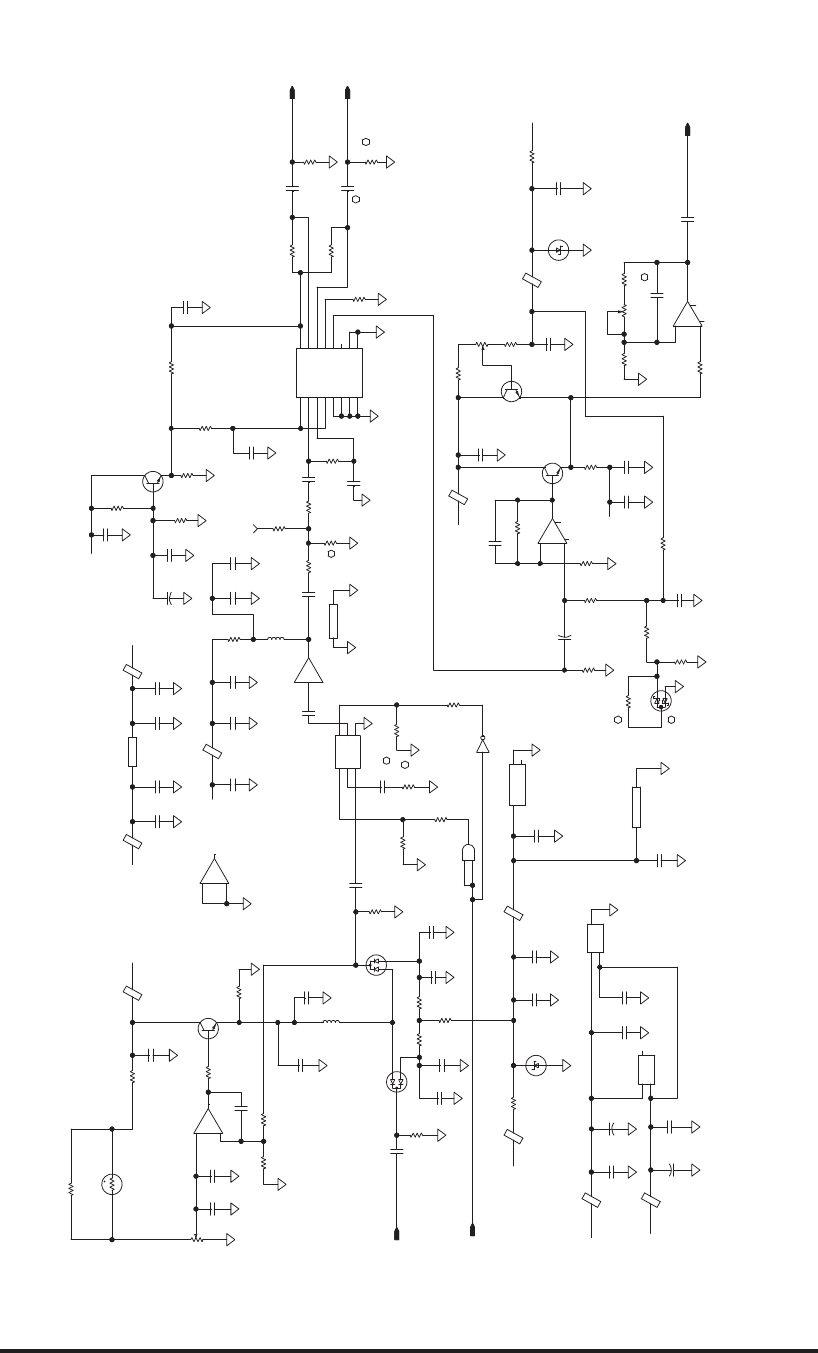
ROCKWELL COLLINS
COMPONENT MAINTENANCE MANUAL with IPL
TDR-94, PART NO 622-9352
(828-7567-005D_3)
TPH6585_03
AG201-86
GND GND
AG201-86
422
200
2 K
3
3
3
1 K
1
49.9
49.9
0.1
0.1
0.1
0.1
0.1
0.1
0.10.1
0.1
0.1
0.1
0.1
0.1
0.1
0.1
0.1
0.1
0.1 0.1
0.1 0.1
0.1
0.1
0.1
0.1
0.1
A1
1 K
1 K
66.5
A1
A1
3
A1
A1
1 K
5.62 K
1.5 K
A1
4.99 K
562
56 PF
+8VDC
1 K
+8VDC
1
+
1 K
A1A1
A1
A1A1
AD847
-
+
A1
0.01
A1A1
0.01
A1
A1
4.99 K
A1
A1
6800 PF
6800 PF A1
A1
A1
562
6800 PF
1 K
6800 PF
1.5
HSMP3814
A1A1
A1
52.3
A1
A1
A1
2 K
A1
A1
A1
A1
5.6
A1
A1
5.6
A1
A1
A1
A1
HSMP3814
1 K
6800 PF
562
0.01
A1
A1
6800 PF
1 K
+8VDC
2222A
A1
4.99 K
A1
A1
082
V+ V-
4.99 K
2222A
A1
+8VDC
A1
A1
A1
A1
A1
MMBT2369AL
AD847
-VS
NC
+VS
AD847
-VS
NC
+VS
AD8309ARU
PADL
VPS2
VPS1
LMLO
PADL
FLTR
VLOG
LMDR
PADL
PADL
COM2
COM1
ENBL
INLO
INHI LMHI
562
A1
A1
+8VDC
1
+
A1
+8VDC
AD847
-
+
MMBT2369AL
+8VDC
1 K
56 PF
562
4.99 K
0
2 K
A1
6800 PF
0
6800 PF
0
6800 PF6800 PF
6800 PF
A1
A1 A1
0.047
A1
A1
MMBZ5231B
5.1 V
MMBZ5231B
5.1 V
A1
5.62 K
1
+
1
+
1 K
A1
A1
511
511
0
A1
3
3
74AHC1G04
082
+
-
A1
A1
A1
74AHC1G04
GND
VCC NC
SN74AHCT1G08DBVR
1.5
AS214-92
GND
J2
V2
J1
J3
V1
3
3
SN74AHCT1G08DBVR
VCC GND
A1
4.32 K
6800 PF0.01 0.01
A1
2 K
-12VDC_IF
-12VDC_IF
-12VDC_IF
-12VDC_IF
49.9
1 K
1 K
1 K
1 K
A1
A1
A1
0.1
A1
0.1
082
-
+
1 K
1 K
BAS70-04
5.11 K
2 K
t
100mVp-p @ -57dBm
ADJ
GAIN
ADJ
TOP
LOG SLOPE
ADJUST
MTL
TOP
12
R189
12
R190
2
1
3
CR9
21
R57
1
2
3
R94
2
3
1
U22
1
2
C70 1
2
C39
12
R169
12
R171
1
2
R167
1
2
R168
2
1
R26
RCVR_VIDEO_SUPP_IF
1
2
R154
12
ZP19
2
1C65
1
2
C24
2
1C146
21
ZP32
12
R187
53
U37
21
ZP45
2
1
ZP13
53
1
46
2
U16
(1,4)
1
2
L10
1
24
U37
53
1
U33
TOP_VIDEO_IF
7
5
6U22
24
U33
12
R186
12
R194
1
2
R204
1
2
R191
12
C83
1
2
C26
1
2
R44
3
1
VR10
3
1
VR1
1
2
C214
(1)
21
ZP12
21
C227
21
C126
21
C66
12
R69
12
C67
12
R68
12
C64
12
R100
12
R176
1
2
R33
1
2
R106
12
C221
1
2
3
R178
3
1
2
Q15
2
3
1
8
6
U2
21
ZP4
(1)
1
2C38
2
1
R109
2
4
5
8
7
110
16
9
12
13
15
3
611
14
U11
5
4
7
U30
7
4
5
U2
2
1
3
Q13
12
ZP37
2
1
3
Q5
21
R8
21
ZP36
84
U22
12
R83
2
1
3
Q3
1
TP1
1
2
R76
12
C130
1
2
C16
2
1
R107 2
1C127
12
R58
1
2
3
CR2
12
ZP11
21
ZP10
12
R64
1
2
R63
1
2
R34
1
2
R52
12
3
CR1
2
1
L12
1
2
C128
21
R59
1
2
C129
12
R108
LMHI_TOP
LMLO_TOP
12
C23
12
C22
12
R145
FROM_FILTER_1
(5)
2
1C184 1
2
C185
6
8
1
3
2
U30
12
R182
1
2
C13
1
2
3
R195
12
C217
1
2
R207 1
2
R47
12
R185
12
R134
1
2
R24
1
2
R156
1
2
R5
2
1
R4
1
2
C150
1
2
C229
1
2
C206
1
2
C205
12
C204
1
2
C198
1
2
C197
1
2
C189
1
2
C140
1
2
C44
1
2
C42
1
2
C48
1
2
C68
1
2
C63
1
2
C69
1
2
C47
1
2
C194
1
2
C97
1
2
C50 1
2
C207
1
2
C193
1
2
C223
1
2
C124
1
2
C224
1
2
C149
1
2
C151
12
R79
12
R78
12
C75
12
R56
12
R62
1
2
R43
1
2
R77
13
U9
24
U9
IF Receiver, DPSK Detector, and LVPS Circuit Card A7 (CPN 687-0727-005), Schematic Diagram
Figure 2032 (Sheet 3 of 7)/GRAPHIC 34-50-96-99B-067-A01
34-50-96 Page 2253/2254
May 18/06
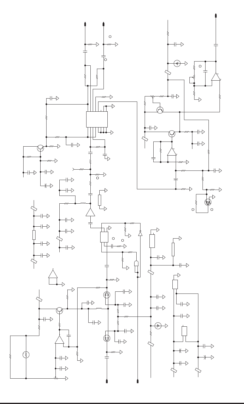
ROCKWELL COLLINS
COMPONENT MAINTENANCE MANUAL with IPL
TDR-94, PART NO 622-9352
(828-7567-005D_4)
TPH6585_04
AG201-86
GND GND
AG201-86
5.11 K
422
200
3
3
3
1 K
1
49.9
49.9
A1
0.1
0.1
0.1
0.1
0.1
0.1
0.1
0.1
0.1
0.1
0.1
0.1
0.1
0.1
0.1
0.1
0.1
0.1
0.1 0.1
0.1
0.1
0.1
0.1
0.1
0.1
0.1
0.01
A1
1 K
AS214-92
GND
J2
V2
J1
J3
V1
A1
A1
366.5
A1
A1
A1
511
511
1 K
5.62 K
A1
A1
4.99 K
56 PF
+8VDC
1
+
A1
A1
1 K
1 K
562
MMBT2369AL
A1A1
A1
A1
0.047
A1
AD847
-
+
AD847
-
+
A1
0.01
A1A1
0.01
A1
A1
4.99 K
4.99 K
A1
2222A
+8VDC
A1
A1
A1A1
562
6800 PF
1 K
1.5
A1A1
A1
A1
A1
6800 PF
52.3
A1
A1
A1
2222A
2 K
5.62 K
A1
A1
A1
A1
5.6
A1
A1
A1
5.6
A1
1
+
A1
1 K
6800 PF
562
0.01
1
+
6800 PF HSMP3814
HSMP3814
+8VDC
A1
A1
+8VDC
082
-
+
A1
A1
A1
1.5
A1
6800 PF
562
A1
+8VDC
MMBT2369AL
1 K
A1
1 K
A1 1 K
4.99 K
2 K
A1
0
0
A1
A1 A1
+8VDC
AD847
-VS
NC
+VS
6800 PF
A1
A1
MMBZ5231B
5.1 V
A1
A1
562
A1
6800 PF
0
AD8309ARU
PADL
VPS2
VPS1
LMLO
PADL
FLTR
VLOG
LMDR
PADL
PADL
COM2
COM1
ENBL
INLO
INHI LMHI
6800 PF
6800 PF
74AHC1G04
GNDVCC
NC
A1
3
A1
MMBZ5231B
5.1 V
3
0
A1
6800 PF
1 K
SN74AHCT1G08DBVR
VCC GND
082
V+ V-
082
+
-
A1
1.5 K
6800 PF
4.32 K
1
+
6800 PF
1 K
0.01
AD847
-VS
NC
+VS
2 K
+8VDC
56 PF
4.99 K
A1
74AHC1G04
-12VDC_IF
-12VDC_IF
-12VDC_IF
-12VDC_IF
1 K
0.1
49.9
A1
3
3
SN74AHCT1G08DBVR 1 K
1 K
1 K
A1
A1
A1
1 K
BAS70-04
2 K
t
2 K
100mVp-p @ -57dBm
GAIN
ADJ
BOTTOM
BOTTOM
ADJUST
MTL
ADJ
LOG SLOPE
12
R123
12
R205
2
1
3
CR12
1
2
3
R95
12
R197
12
R181
1
2
R180
1
24
U38
2
1
R38
1
2
C225
1
2
R172
24
U34
1
2
R41
1
TP2
12
C222
1
2
R170
12
ZP22
5
4
7
U31
(1,3)
1
2
C28
12
ZP23
1
2
R74
2
1C147
12
C91
12
R188
21
C228
12
R192
21
ZP43
7
5
6U24
84
U24
53
U38
BOT_VIDEO_IF
1
2
R16521
C134
12
R193
3
1
VR11
53
1
U34
21
ZP48
(2)
2
1
ZP20
21
C138
12
C27
2
4
5
8
7
110
16
9
12
13
15
3
611
14
U14
12
R101
12
C135
1
2
R112
3
1
VR2
1
2
C132
7
4
5
U4
21
ZP21
12
R175
12
R102
12
R88
1
2
R84
21
R66
1
2
3
R179
1
2
3
R196
3
1
2
Q16
21
ZP44
(1)
2
1
R113
12
C251
2
L32
2
3
1
U24
FROM_FILTER_2 1
2
3
CR4
1
23
CR3
12
C139
1
2
C58
1
2
C36
2
1
R111 2
1C137
12
R75
1
2C40
12
R105
1
2
R104
1
2
R92
1
2
R89
2
1
3
Q4
1
2
R93
12
C133
2
1
L31
21
R61
1
2
C131
12
R110
21
ZP24
2
1
3
Q6
12
R103
12
R146
(5)
2
1C187 1
2
C186
21
ZP42
12
ZP41
2
3
1
8
6
U4
6
8
1
3
2
U31
1
2
C215
2
1
3
Q14
1
2
R177
2
1
R46
12
R183
1
2
C35
12
C220
1
2
R48
LMHI_BOT
LMLO_BOT
12
R19
1
2
R184
12
R208
1
2
R209
1
2
R157
53
1
46
2
U32
2
1
R166
2
1C136
1
2
C154
1
2
C153
1
2
C230
1
2
C196
1
2
C211
1
2
C209
1
2
C199
1
2
C190
1
2
C142
1
2
C123
1
2
C141
1
2
C71
1
2
C79
1
2
C80
1
2
C119
1
2
C120
1
2
C121
1
2
C122
12
C208
1
2
C59
1
2
C94
1
2
C195
1
2
C210
1
2
C226
1
2
C125
1
2
C152
1
2
C200
RCVR_VIDEO_SUPP_IF
12
R114
12
R115
12
C92
12
R67
1
2
R91
1
2
R116
12
R206
13
U15
24
U15
IF Receiver, DPSK Detector, and LVPS Circuit Card A7 (CPN 687-0727-005), Schematic Diagram
Figure 2032 (Sheet 4 of 7)/GRAPHIC 34-50-96-99B-067-A01
34-50-96 Page 2255/2256
May 18/06
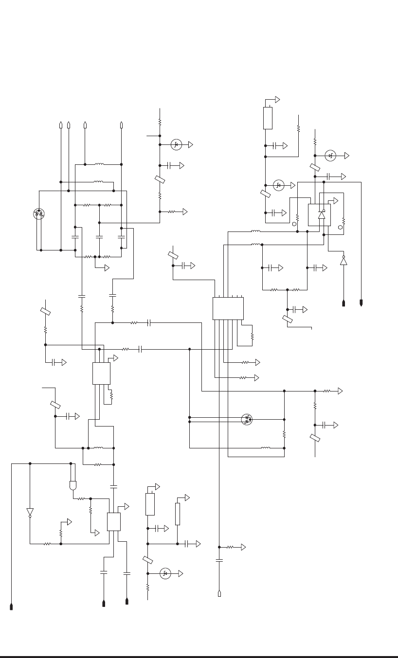
ROCKWELL COLLINS
COMPONENT MAINTENANCE MANUAL with IPL
TDR-94, PART NO 622-9352
(828-7567-005D_5)
TPH6585_05
0
2.74 K
2.74 K
2.74 K
2 K
10 K
+8VDC
2.87 K
4.75 K
6800 PF
+8VDC
A1
0.1
470 NH1 K
562
74AHC1G04
GND
VCC
NC
A1
A1
0.1
3.9
A1
74AHC1G04
A1
A1
A1
1016
LE GND
V-
V+
+
-
82.5
3
10 K
10 K
3.9
0.1
MMBZ5231B
5.1 V
A1
74AHC1G04
GND
VCC
NC
AS214-92
GND
J2
V2
J1
J3
V1
SN74AHCT1G08DBVR
74AHC1G04
A1
1 K
1 K
A1
0.1
6800 PF
6800 PF
UPC1663GV
OUT1
OUT2
V+
IN1
G1B
G1A
IN2
V-
A1
A1
A1
+8VDC
0.1
MMBZ5231B
5.1 V
MMBZ5231B
5.1 V
1 K
+8VDC
825
825 33 PF
825
33 PF
33 PF
17.8 K
17.8 K
A1
330 PF
17.8 K
0.1
MMBZ5231B
5.1 V
1 K
BAS70-04
3.9 3.9
33 PF
33 PF
17.8 K
A1
A1
A1
422
A1
1 K
-12VDC_IF
0.1
-12VDC_IF
A1
BAS70-04
49.9
A1
A1
0.1
1 K
A1
1 K
A1
6800 PF
0.1
A1
A1
0.1
+8VDC
A1
27 PF
27 PF
0.1
A1
A1
A1
+5V_A
+5V_A
3
SN74AHCT1G08DBVR
VCC GND
A1
A1
MC1496BD
OUT
OUT
CARRI
ICAR R
SIGI
SIGI
GNADJ
GNADJ
BIAS
NC
NC
NC
NC
VEE
294
825
33 PF
+8VDC
49.9
680 NH
HIGH = DATA OUTPUT
TOP_SEL=HIGH
1
2
L21
12
R21
1
2
C90
1
2
R39
12
R70
5
1
4
10
8
2
37
9
11
6
12
13
14
U3
53
U39
CARR-
CARR+
SIG+
SIG-
C192
(6)
(6)
(6)
(6)
(6)
1
2
C49
1
2
C86
1
2
C89
12
ZP51
1
2
C18
12
ZP49
21
ZP46
1
2
C46
21
C3
1
2
R36
1
2
R35
1
2
C45
2
1
ZP31
12
R1
21
3
CR7
1
2
C176
21
ZP50
1
2
R199
12
R142
1
2
R139
12
C100
12
C101
1
2
L20
1
2
L17
2
13
CR6
12
R32
1
3
VR3
1
2
C43
12
ZP25
1
2
R138
12
C10
1
2
R137
1
2
R122
12
C95
1
2
C93
1
2
R40
12
C98
12
R65
12
R42
12
R201
1
3
VR14
3
1
VR15
1
2
C41
12
ZP5
8
1
2
7
4
5
6
3
U41
12
ZP33
DPSK_TOP_SEL_IF
21
C2
2
1
C102
LMHI_TOP
LMHI_BOT
1
2
C96
1
2
R198
12
R200
2
4
U17
1
2
4
U39
53
1
46
2
U40
(4)
53
1
U17
(3)
(1)
1
3
VR9
1
2
C157
1
2
L14
12
R147
12
R153
12
R152
3
2
5
8
7
1
4
6
U7
(1)
24
U36
1
2
L13
2
1C175
53
1
U36
(1)
12
R30
1
2
R31
1
2
L7
12
ZP3
1
2
C34
DPSK_ENABLE_IF
DPSK_DATA_IF
2
1
C8
12
R120
1
2
R29
1
2
R99
12
R25
1
2
R121
1
2
R85
1
2
R80
12
R124
IF Receiver, DPSK Detector, and LVPS Circuit Card A7 (CPN 687-0727-005), Schematic Diagram
Figure 2032 (Sheet 5 of 7)/GRAPHIC 34-50-96-99B-067-A01
34-50-96 Page 2257/2258
May 18/06
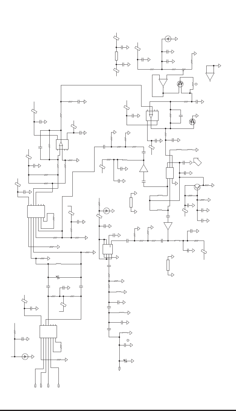
ROCKWELL COLLINS
COMPONENT MAINTENANCE MANUAL with IPL
TDR-94, PART NO 622-9352
(828-7567-005F_6)
TPH6585_06
768
2.74 K
0
33.2
3.65 K
18.2
34.8
34.8
AG201-86
GND GND
AG201-86
AG201-86
GND GND
AG201-86
3
A1
10 PF
200
2.7 PF
1.8 PF
1.8 PF
52.3
20
20
200
3.3 PF
A1
MMBZ5235B
6.8 V
4.99 K
A1
10 K
200
200
10 K
A1
-12VDC_IF
A1
A1
A1
1.07 K
768 768 6800 PF
A1
2222A
+8VDC
0.1
A1
5.11 K
A1
4.99 K
A1
49.9
A1
1 K
0.1
A1 A1
0.1
1800 PF
1 K
1.5
A1 A1
1800 PF
+8VDC
1800 PF
0.1
A1
A1A1
+8VDC
0.1
A1
4.99 K
4.99 K
0.1
A1
A1
12093
OUT
SW2
SW1
IN
INVCC
GND
SB
562
A1
A1
A1
330 NH 330 NH
2 K
0.1
A1
1800 PF
680 PF
6.19 K
560 PF
0.1
0.1
A1
BAS70-04
-12VDC_IF
TST SEL
A1
1800 PF
1800 PF
A1
470 NH
11 PF
470 NH
A1
A1
A1
A1
A1
0.1
+8VDC
OP291GS
V-
V+
A1
OP291GS
+
-
2 K 2 K
-12VDC_IF
A1
1 K
0.1
470 NH
A1
1800 PF
1.07 K
A1
0.1
A1
MMBZ5231B
5.1 V
MMBZ5231B
5.1 V
A1
0.1
+8VDC
562
0.1
A1
A1
+5V_B
0.1
A1
47 PF
47 PF
A1
1.5
A1
1800 PF
A1
+5V_B
1 K
0.1
A1
A1
3.57 K
+5V_B
+8VDC
A1
A1
A1
+8VDC
49.9
0.1
A1
0.1
0.1
A1
-12VDC_IF
BAS70-04
-12VDC_IF
.22
A1
0.1
0.1
A1
A1
10 PF
2.5-10 PF
2.5-10 PF
A1
470 NH
0
A1
MC1496BD
OUT
OUT
CARRI
ICARR
SIGI
SIGI
GNADJ
GNADJ
BIAS
NC
NC
NC
NC
VEE
MC1496BD
OUT
OUT
CARRI
ICARR
SIGI
SIGI
GNADJ
GNADJ
BIAS
NC
NC
NC
NC
VEE
100
2 K
AD797
V-
V+
OFFST
OFFST
COMP
+
-
4.99 K
22 PF
0.1
A1
-12VDC_IF
+8VDC
+8VDC
1 K
OP291GS
+
-
A1
1 K
22 PF
AD797
V-
V+
OFFST
OFFST
COMP
+
-
0.1
A1
A1
MAX2606EUT-T
VCC
IND
TUNE
OUT+
OUT-
GND
3
60 MHZ BPF
7.4dB
15dB
1
3
4
65
2
U20
1
2
C103
8
2
3
1
5
6
7
4
U1
12
C77
12
R6
2
3
1
U44
1
23
R223
12
ZP40
1
2
C51
12
C14
12
R144
8
2
3
1
5
6
7
4
U8
12
ZP62
12
R97
12
R72
5
1
4
10
8
2
37
9
11
6
12
13
14
U5
5
1
4
10
8
2
37
9
11
6
12
13
14
U6
(5)
(5) SIG-
(5)
(5)
SIG+
CARR-
12
R150
CARR+
1
2
L161
2
C110
1
2
C104
1
2
C188
1
2
C170 1
2
C169
1
2
L19 2
13
CR8
12
ZP55
1
2
C202
1
2
C109
1
2
C108
12
R22
(5)
12
ZP63
1
2
R203 1
2
C85
1
2
R96
12
ZP38
1
2
C9
1
2
L9
12
C31
12
C30
1
2
C57
1
2
C54
12
R219
1
2
C84
1
3
VR6
1
3
VR13
12
ZP61
12
ZP59
1
2
C172
12
R81
1
2
C76
1
2
L8
1
2
C53
1
2
R2
12
ZP58
12
ZP57
1
2
R98
1
2
R87
6
5
7
U44
84
U44
12
ZP56
1
2
C173
1
2
L2
1
2
C191
1
2
L1
1
2
C62
1
2
C73
1
2
L18
2
13
CR5
1
2
C174
1
2
C158
1
2
C12
1
2
R135
1
2
C81
12
C21
1
2
C112
1
2
R86
1
2
L4
1
2
L3
12
R216
1
8
6
3
7
4
2
5U19
12
ZP52
1
2
C19
12
R14
12
R13
12
ZP53
1
2
C165
12
ZP47
1
2
C113
1
2
C52
12
ZP7
1
2
C20
1
2
L11
12
ZP39
1
2
R7
1
2
C6
1
2
C88
1
2
C87
1
2
R3
12
R23
1
2
R71
1
2
R90
1
2
C171
12
ZP54
2
1
3
Q7
21
C183
12
R73
12
R136
1
2
R212
1
2
R119
1
2
R218
1
2
R217
1
2
R117
1
2
R11
3
1
VR7
12
C182
1
2
R20
1
2
R16
1
2
R18
12
R214
12
C216
12
C213
12
C181
1
2
R143
1
2
C192
C192
13
U10
24
U10
13
U12
24
U12
1
2
R15
1
2
R17
12
R215
1
2
R221
12
R158
12
R140
1
2
R222
12
R202
J1
IF Receiver, DPSK Detector, and LVPS Circuit Card A7 (CPN 687-0727-005), Schematic Diagram
Figure 2032 (Sheet 6 of 7)/GRAPHIC 34-50-96-99B-067-A01
34-50-96 Page 2259/2260
May 20/10
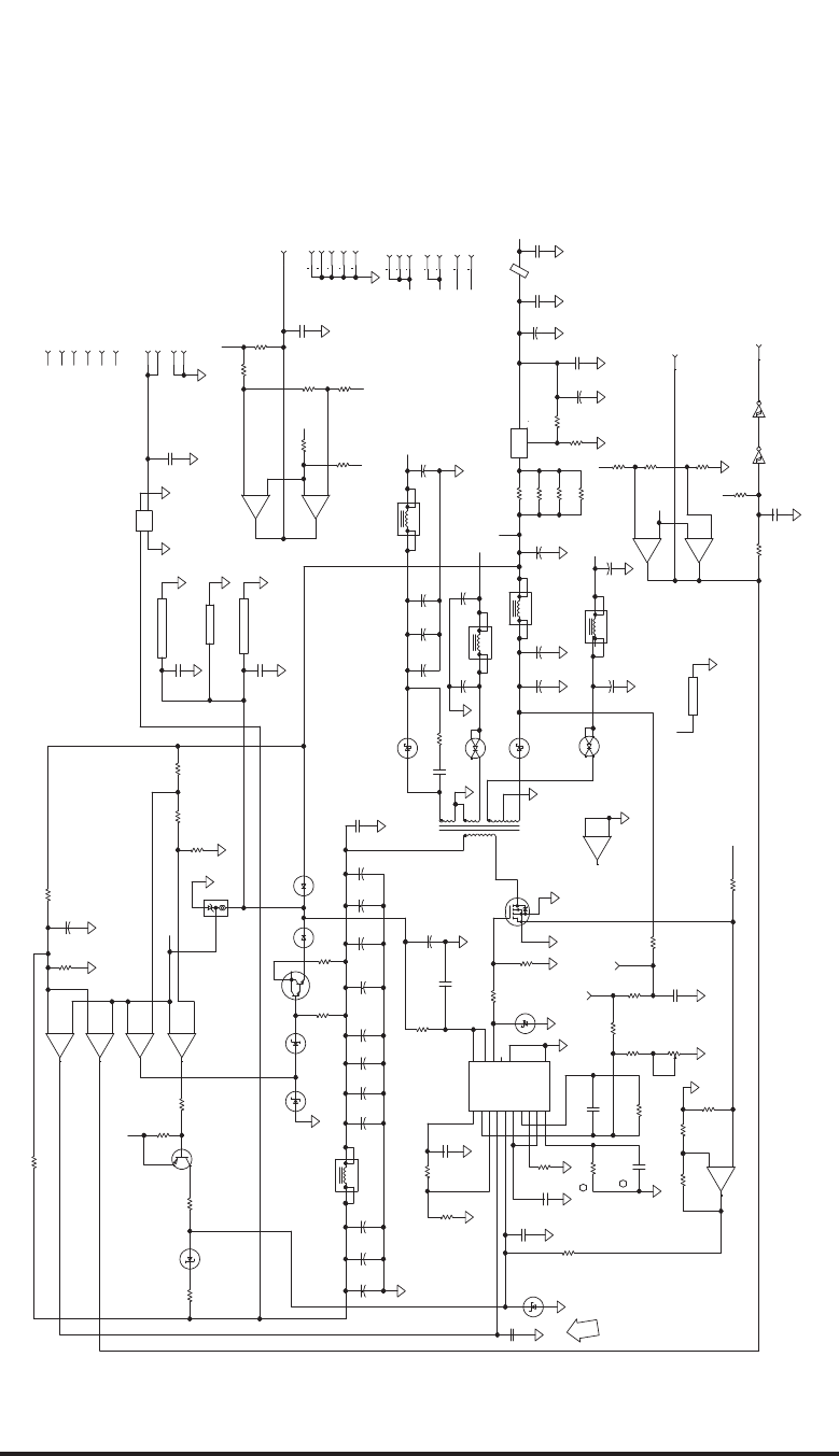
ROCKWELL COLLINS
COMPONENT MAINTENANCE MANUAL with IPL
TDR-94, PART NO 622-9352
(828-7567-005G_7)
TPH6585_07
10
10
10
0.001
0.047
0.33
0.01
0.01
4.7
+
0
A1
0.1
0.1
A1 A1
A1
A1
A1
A1
A1
A1 A1 A1
A1
A1
A1
A1
A1
A1
A1
A1
A1A1
A1
A1
A1
A1
A1 A1 A1
A1
A1
150
+
150
+
150
+
150
+
150
+
100
+
100
+
100
+
+5VDC
+5VDC
2901
VCC VEE/GND
+12VDC
-12VDC
+5VDC
+5VDC
10 K
74HC14
43.2 K
5.11 K 2.43 K
10 K
2907
5.11 K
MMBZ5257B
33 V
2901
+
-
2901
+
-
12.1 K
150 K
112
22.1
10 K
22
+
22
+
22
+
22
+
22
+
22
+
22
+
22
+
22
+
22
+
13 K
4.32 K 56.2 K
5.36 K
1825
VC
PGND
OUTB
OUTA
CT
RT
CLK
E/AOUT
RAMP
ILIM
SS
VREF
INV
NINV
VCC
GND
0.22
10 K
100 K
2 K
9.09 K
MBRS120T3
3.3
330 PF
0.22
10
1.21 K
MMBZ5231B
5.1 V
12.1 K 1.62 K
845
0.022 1300
+
320
320
50SQ080
357
2901
+
-
+2.5V_REF
39.2 K
10 K
2901
+
-
51.1 K
+12VDC
4.75 K
11 K
1 K
20 K
74HC14
22.1
221 K
-12VDC -5VDC
-12VDC
22
+
39.2 K
39.2
10
2901
+
-
0.0047
-5VDC
+5VDC
39.2 K
2901
+
-
2901
VCC VEE/GND
74HC14
VCC GND
75 K
33072
+
-
0.22
0.22
33072
VCC VEE
+2.5V_REF
AD580TH
+12VDC
2.21 K
+2.5V_REF
+5VDC
-5VDC
3
3
2901
+
-
2901
+
-
33072
+
-
IRC640
121 K
680 PF
MMBD6050X MMBD6050X
100
+
100
+
MMBZ5237B
8.2 V
A1
A1
A1
A1 A1
A1
A1
A1
A1
A1
A1
A1
A1
A1
A1
A1
A1
A1
A1
A1
A1
0.1
EMI
A1
90
90
43
43
108
MMBZ5245B
15 V
10
+12VDC
2 K
LM317M
RGLTR +8VDC
1
+
10
+
0.1
1
+
A1
A1
0
10 K
10
(N.C.)
(N.C.)
(N.C.)
HV OFF (N.C.)
+40 V MON (N.C.)
+70 V MON (N.C.)
VE
12
R45
1
2
R626
1
2
R622
1
2
C601
1
2
C610
1
2
C505
1
2
C11
12
ZP9
3
1
2
U601
1
2
R610
12
R625
31
VR502
1
23
4
L503
1
23
4
L500
1
23
4
L502
1
23
4
L501
1
23
4
L504
AIRCRAFT_PWR
PSG
BCG
CB
FL500
1
2
9
7
4
3
6
8
10
T500
1
2
C604
+5_V_MON
31
VR500
1
2C514
1
2C504
31
CR503
31
CR502
1
2
C606
12
R620
5
1
3
42
Q500
7
5
6
U600
13
11
10
U501
4
5
2
U501
LVPS_MON
32 J7
12
R607
1
2
3
U503
84
U600
1
2
C528
2
1C519
1
3
2
U600
12
R614
14 7
U602
312
U502
4
5
2
U502
PWR_ON_CLEAR
1
2
R519
13 J7
3J7
6J7
1
2
C507
12 J7
8
9
14
U502
12
R624
1
2
R500
12
R621
2
1C521
1
2
R612
12
R609
34
U602
1
2
R513
1
2
R511
12
R516
1
2
R515
1
2
R512
13
11
10
U502
1
2
R517
1
2
R518
1
7
6
U502
12
R611
12
CR501
2
41
3
CR504
3
14
2
CR505
1
2
C524
12
C609
12
CR500
12
R601
12
R600
3
1
VR600
1
2
R604
1
2
R510
12
C607
1
2
C500
1
2
C509
1
2
CR600
1
2
R617
1
2
3
R507
12
R501
1
2
R619 1
2
C605
4
5
6
7
1
2
8
9
3
14
11
16 15
13
12
10
U500
1
2
R623
12
R505
12
R509
1
2
R508
2
1C525
1
2
C513
2
1C517 1
2
C510
2
1C512 1
2
C506 1
2
C522 1
2
C527
2
1C523
1
2
C526
1
2
R503 1
2
R502
3
12
4
Q501
12
R615
1
2
R603
8
9
14
U501
1
7
6
U501
31
VR601
12
R506
2
1
3
Q502
1
2
R504
12
R608
12
R613
12
R514
12
U602
12
R618
10 J7
9J7
7J7
5J7
4J7
8J7
2J7
1J7
15 J7
16 J7
34 J7
30 J7
18 J7
28 J7
17 J7
26 J7
24 J7
22 J7
20 J7
14 J7
123
U501
VF
1
TP602
1
TP601
1
2
C503
1
2
C508 1
2
C515
1
2
C501 1
2
C502 1
2
C516
1
2
C511 1
2
C518
1
2
C180
2
1C218
12
R616
1
2
C602 1
2
C603
1
2
C520
1
2
C600
12
C608
1
2
C611
12
R159
12
R160
12
R161
J2
IF Receiver, DPSK Detector, and LVPS Circuit Card A7 (CPN 687-0727-005), Schematic Diagram
Figure 2032 (Sheet 7 of 7)/GRAPHIC 34-50-96-99B-067-A01
34-50-96 Page 2261/2262
May 20/10

ROCKWELL COLLINS
COMPONENT MAINTENANCE MANUAL with IPL
TDR-94, PART NO 622-9352
DISASSEMBLY
TASK 34-50-96-000-801-A01
1. Introduction
A. Disassemble the TDR-94/94D only when repair is necessary and only to the extent
necessary for repair or troubleshooting. Perform the Acceptance Test or Final Performance
Test given in the Testing and Fault Isolation section of this manual to determine if repair is
required. If repair is needed some disassembly will likely be required.
TASK 34-50-96-000-802-A01
2. Precautions and General Techniques
WARNING: REMOVE POWER CABLE BEFORE DISASSEMBLING ANY PORTION OF
THE EQUIPMENT. DISASSEMBLING THE EQUIPMENT WITH POWER
CABLE CONNECTED IS DANGEROUS TO LIFE AND MAY CAUSE VOLTAGE
TRANSIENTS THAT CAN DAMAGE THE EQUIPMENT.
CAUTION: THIS UNIT CONTAINS ESDS (ELECTROSTATIC DISCHARGE
SENSITIVE) COMPONENTS THAT CAN BE DAMAGED BY IMPROPER
HANDLING. BEFORE REMOVING THE COVER OR ATTEMPTING
TO REPAIR ANY OF THE CIRCUIT CARDS, CAREFULLY READ THE
ESDS HANDLING INSTRUCTIONS ON THE GENERAL ADVISORIES
PAGE IN THE FRONT OF THIS MANUAL.
A. Do not disassemble unless absolutely necessary and only to the extent necessary for repair
or troubleshooting. Carefully note the order of disassembly to ensure correct reassembly.
B. Mark or otherwise identify, all disconnected electrical wiring. Make a note of color coding,
placement of leads, and method of applying insulation (if any) before soldering or removing
any electrical parts. Refer to the advisories page in the front of this manual for cautions and
warnings that must be observed.
TASK 34-50-96-000-803-A01
3. Disassembly Procedures
SUBTASK 34-50-96-000-001-A01
A. General
(1) Refer the Assembly Identification Diagram, Figure 2/GRAPHIC 34-50-96-99B-002-A01,
in the Description and Operation section of this manual for a module location diagram of
the TDR-94/94D. The TDR-94/94D consists of three major subassemblies. The center
T-shaped module is called the Main Chassis Assembly and contains the High Voltage
Power Supply Circuit Card A1 at the front. The center section contains the CPU-I/O
Programmed Assembly A5 on the left (as viewed from the front) and the Video Processor
Circuit Card A6 on the right. Each of these cards is attached to a rear connector.
34-50-96 Page 3001
May 18/06

ROCKWELL COLLINS
COMPONENT MAINTENANCE MANUAL with IPL
TDR-94, PART NO 622-9352
(2) The module on the left is the RFPA Chassis Assembly. It consists of the Power Amplifier
Circuit Card A2 on the outer side directly under the outside cover, the Synthesizer
Circuit Card A4 on the inner side to the back of the unit, and the Modulator Circuit Card
A3, also on the inner side but at the front of the module.
(3) The module on the right is the IF Receiver Chassis Assembly. It consists of the IF
Receiver, DPSK Detector, and LVPS Circuit Card A7.
(4) If you are using a test panel built from procedures in an earlier version of the
TDR-94/94D Component Maintenance Manual, you must also remove the unit from the
MMT-150 Mounting Tray. When the modules are disassembled, you will find that you
must also disassemble the MMT-150 Mounting Tray. Refer to MMT-150 Mounting Tray
disassembly instructions in paragraph F below.
(5) To separate these three chassis assemblies make sure the unit is disconnected from
any power source. If you are using a test panel built from procedures in an earlier
version of the TDR-94/94D Component Maintenance Manual, you must also remove
the unit from the MMT-150 Mounting Tray.
SUBTASK 34-50-96-000-002-A01
B. Separation of the RFPA Chassis Assembly from the Main Chassis Assembly
(1) Locate the six screws which have noticeably larger heads than the others.
(a) Another two screws are located near the front edge of the assembly and are about
1/4-inch long.
(b) Two are located about 3/4-inch forward of the upper and lower corners at the rear of
the assembly. These screws are 2-inches long and extend into the Main Chassis
Assembly.
(c) The remaining two screws are located about 6-3/4 inches forward of the rear edge,
along the top and bottom edges. These two screws are also 2-inches long and
extend into the Main Chassis Assembly.
(2) With these six screws removed you should be able to separate the RFPA Chassis
Assembly from the Main Chassis Assembly. As soon as the assemblies are clear of
each other, you will notice the internal cabling. Try not to put stress on the cables,
especially the two RF coax cables/connectors at the rear. Excessive stress can cause
damage to the circuit board where the mating connectors are attached. These two
cables are the RF link to the receiver. If circuit testing is necessary on either of the two
circuit cards on the Main Chassis Assembly, disconnect the coax cables and install
extender cables. You will notice that the IF Receiver Chassis Assembly must also be
separated in order to do this. These extender cables will allow additional module
separation for increased access to the circuit cards.
34-50-96 Page 3002
May 18/06

ROCKWELL COLLINS
COMPONENT MAINTENANCE MANUAL with IPL
TDR-94, PART NO 622-9352
(3) At the front you will notice a cable that has of four separate conductors. This is the high
voltage power supply output cable; one pair each for ±70 V dc and ±35 V dc. The
Special Tools, Fixtures, Equipment, and Consumables Section also lists an extender
for this cable if needed.
(4) You will also notice a ribbon cable between the Main Chassis Assembly and the RFPA
Chassis Assembly. If it is necessary to disconnect this cable, pull straight away from the
connector using the white plastic cable pulls attached. Do not tug on the ribbon cable;
this can cause the connector to separate, possibly resulting in an open or intermittent
connection.
SUBTASK 34-50-96-000-003-A01
C. Separation of the IF Receiver Chassis Assembly from the Main Chassis Assembly
(1) Locate the six screws which have noticeably larger heads than the others.
(a) Two screws are located near the front edge of the assembly and are about 1/4-inch
long.
(b) Another two screws are located about 3/4-inch forward of the upper and lower
corners at the rear of the assembly. These screws are 2-inches long and extend
into the Main Chassis Assembly.
(c) The remaining two screws are located about 6-3/4 inches forward of the rear edge,
along the top and bottom edges. These two screws are also 2-inches long and
extend into the Main Chassis Assembly.
(2) With these six screws removed you should be able to separate the IF Receiver Chassis
Assembly from the Main Chassis Assembly. Separate the two assemblies slowly
and carefully. As soon as the assemblies are clear of each other you will notice
the internal cabling. Try not to put stress on the cables, especially the two RF coax
cables/connectors at the rear. Excessive stress can cause damage to the circuit board
where the mating connectors are attached. These two cables are the RF link to the
receiver. If circuit testing is necessary on either of the two circuit cards on the Main
Chassis Assembly, it is best to disconnect these coax cables and install extender
cables. You will notice that the PA Chassis Assembly must also be separated in order to
do this. These extender cables will allow additional module separation for increased
access to the circuit cards.
(3) You will also notice a wide cable connecting the Main Chassis Assembly to the IF
Receiver, DPSK Detector, Low Voltage Power Supply Chassis Assembly, with a shorter
and narrow ribbon cable at the front.
34-50-96 Page 3003
May 18/06

ROCKWELL COLLINS
COMPONENT MAINTENANCE MANUAL with IPL
TDR-94, PART NO 622-9352
SUBTASK 34-50-96-000-004-A01
D. RFPA Chassis Disassembly
(1) Repair, and consequently disassembly of the RFPA Chassis Assembly, is only
authorized for Collins Authorized Service Centers.
SUBTASK 34-50-96-000-005-A01
E. IF Receiver Chassis Disassembly
(1) The IF Receiver Chassis Assembly can be disassembled only to the extent needed to
gain access to the low voltage power supply. Repair, and consequently disassembly of
the remaining assembly, is only for Collins Authorized Service Centers.
NOTE: Any Collins Authorized Repair facility is authorized to disassemble and repair
any of the Main Chassis Assembly. This includes the two center digital circuit
card assemblies, as well as the high voltage power supply located at the front
of this assembly. Disassembly of this module is readily apparent.
SUBTASK 34-50-96-000-006-A01
F. MMT-150 Mounting Tray Disassembly Instructions
(1) If you are using a test panel built from procedures in an earlier version of the
TDR-94/94D Component Maintenance Manual, you must also disassemble the
MMT-150 Mounting Tray. This is necessary to allow the RFPA Chassis Assembly, which
contains the antenna connector(s), to separate from the Main Chassis Assembly, which
contains the two rear main connectors. With the UUT removed from the Mounting Tray,
do the steps that follow:
(a) Remove the four cross-point screws that hold the MMT-150 connector mounting
plate to the side rails.
(b) Remove the four hex keying socket screws that hold the two rear main connectors
in the MMT-150 rear plate.
(c) If the MOV suppressor is connected to the power wires, disconnect those wires
from the MOV and tape or cap the ends to prevent accidentally shorting of the
power source.
(d) Slide the two connectors forward from the connector mounting plate a few inches.
This should allow enough space to tip each connector slightly so that each
connector can be drawn back out through the connector mounting plate. Carefully
remove each connector separately to minimize stress on the wires and damage
to the connector pins. You should now have the cables and connectors free from
the connector mounting plate.
34-50-96 Page 3004
May 18/06

ROCKWELL COLLINS
COMPONENT MAINTENANCE MANUAL with IPL
TDR-94, PART NO 622-9352
CLEANING
TASK 34-50-96-100-801-A01
1. Introduction
A. Refer to Rockwell Collins Avionics Standard Shop Practices Manual (CPN 523-0768039).
34-50-96 Page 4001/4002
May 18/06

ROCKWELL COLLINS
COMPONENT MAINTENANCE MANUAL with IPL
TDR-94, PART NO 622-9352
INSPECTION/CHECK
TASK 34-50-96-200-801-A01
1. Introduction
A. This section gives special instructions necessary to examine the condition of assemblies in
this equipment. Refer to the Fits and Clearances section for applicable tolerances for parts
that wear. For standard equipment checks, obey the procedures given in the Rockwell
Collins Avionics Standard Shop Practices manual.
TASK 34-50-96-200-802-A01
2. Procedures
A. Refer to all warnings and cautions in the General Advisories paragraph in the Introduction
section of this manual. Refer to all warnings and cautions in the Rockwell Collins Avionics
Standard Shop Practices manual.
B. No special instructions are necessary for the inspection of this equipment.
34-50-96 Page 5001/5002
May 18/06
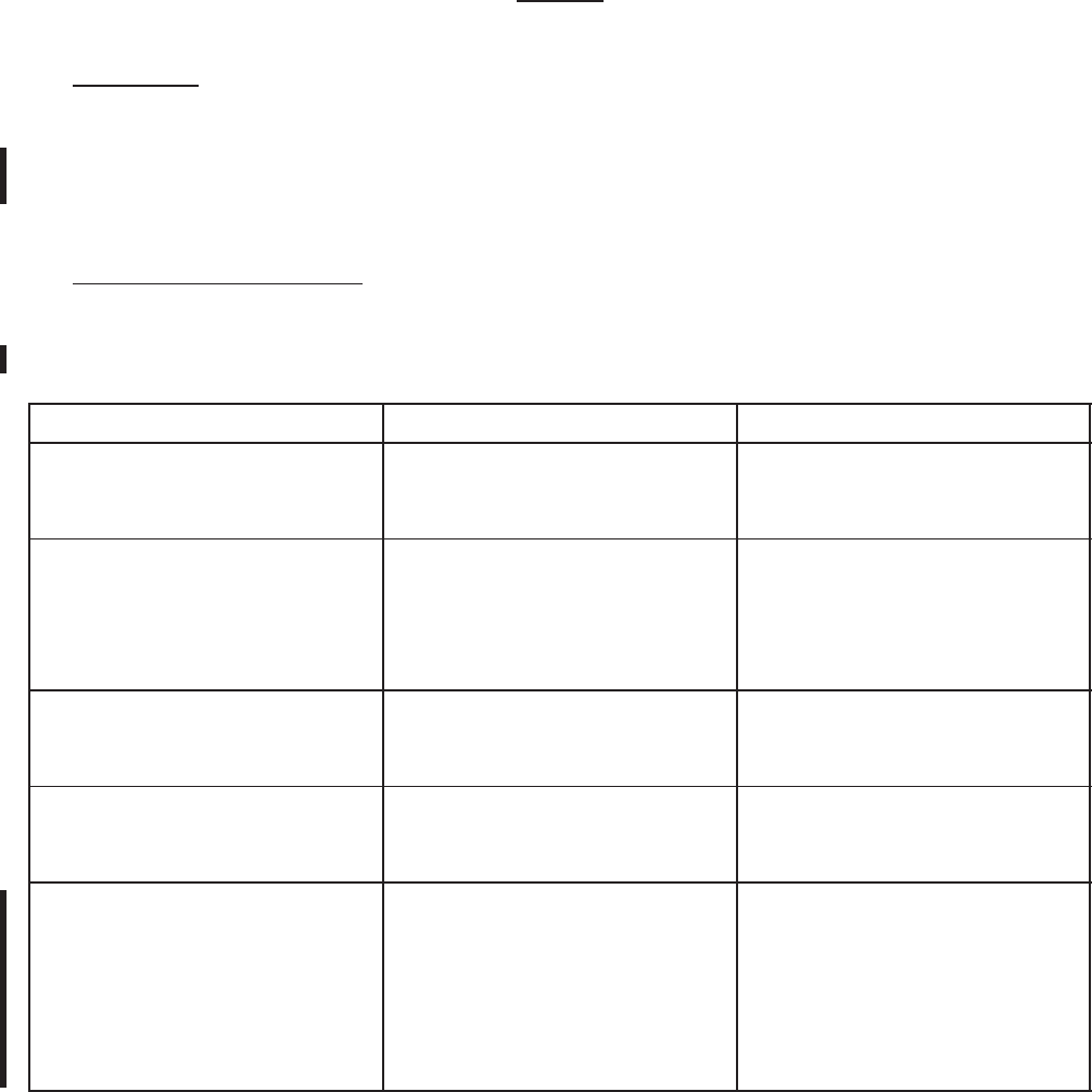
ROCKWELL COLLINS
COMPONENT MAINTENANCE MANUAL with IPL
TDR-94, PART NO 622-9352
REPAIR
TASK 34-50-96-300-801-A01
1. Introduction
A. This section provides repair information specifically for the TDR-94/94D ATC/Mode S
Transponder. This includes the use of adhesives, sealants, lubricants, etc. Refer to Rockwell
Collins Avionics Standard Shop Practices Instruction Manual for standard repair procedures.
TASK 34-50-96-300-802-A01
2. Repair Tools and Supplies
A. Refer to Table 6001/Table 34-50-96-99A-029-A01 below for a list of adhesives, sealants,
and lubricants that are used for repair of the TDR-94/94D.
DESCRIPTION SUPPLIER USE
Rosin-core solder (60% Sn/40%
Pb)
Cen-Tri-Core energized rosin core
or equivalent (CPN 005-0965-000
for a 1-lb spool)
General soldering
Acrylic coating Columbia Technical Corp.,
HumiSeal 1B31 (CPN
821-0650-020 for 1-gallon
container, CPN 821-0650-040 for
12-oz spray can)
Coat and seal repaired
components on circuit board
Cleaning solvent Barton Solvents Inc. Toluene
(CPN 838-2528-010 for 1-gallon
container)
Remove HumiSeal 1B31 from
circuit cards
Cleaning solvent Allied Signal Inc., Genesolv 2004M
(CPN 838-2526-020 for 5-gallon
container)
Remove flux residue from circuit
cards
I-inch wide electrical tape
(insulation)
CHR Ind. Inc., an ARMCO
Co., New Haven, CT,
CHR-K109 (CPN 014-1375-070)
Used on the RFPA chassis
assembly to insulate areas of
modulator cca A3 from the
chassis. Used on -004 and -005
status Video Processor cca A6
to insulate Y100 from the circuit
board.
Repair Materials Required. Cont.
Table 6001/Table 34-50-96-99A-029-A01
34-50-96 Page 6001
May 18/06

ROCKWELL COLLINS
COMPONENT MAINTENANCE MANUAL with IPL
TDR-94, PART NO 622-9352
DESCRIPTION SUPPLIER USE
RTV adhesive Dow Corning Corp., RTV-3145,
(CPN 005-3167-010 for a 3-oz
tube)
Used on the HVPS cca A1 to bond
capacitors C1 through C14 to the
circuit board. Used to bond RF
beads to pins of connector P2 on
cca A5A1 . Also used to bond Y1
to circuit board of cca A5A1, On
-004 status Video Processor cca
A6 used to bond Y100 to circuit
board and RF beads to pins of
connector P1. On -005 status
VideoProcessorccaA6usedto
bond Y100 and C123 to circuit
board and RF beads to pins of
connector P1. On -006 status
Video Processor cca A6 used
to C123 to circuit board and RF
beads to pins of connector P1. On
cca A7, used to bond numerous
capacitors to circuit board.
Conductive adhesive Emerson and Cuming Inc.,
Canton, MA, Eccodbond (CPN
005-0721-000), Specify size
(quantity) when ordering.
Used to secure FL301 and FL302
to cca A2.
Uniset adhesive Emerson and Cuming Specialty,
Canton, MA, D-124F-1RED (CPN
838-0002-010). Supplied in 10 cc
void-free syringes
Used to secure C129 to cca A2,
CR227 and CR228 to cca A5, and
several components on cca A6.
Heatsink compound Dow Corning Corp., DC340-5OZ,
(CPN 005-1234-020 for a 5-oz
tube)
Applied to mounting surface of
transistors Q102, Q103, Q104,
and Q105 on cca A2.
Thread sealant Loctite Corp., Vibratite (CPN
005-2308-0010), supplied in
10-cm3 bottles
Used to secure screws when no
other locking means is provided.
Repair Materials Required. Cont.
Table 6001/Table 34-50-96-99A-029-A01
34-50-96 Page 6002
May 18/06
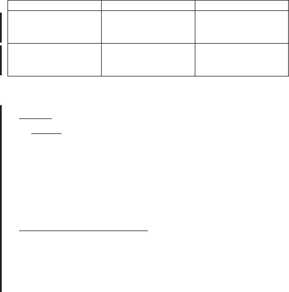
ROCKWELL COLLINS
COMPONENT MAINTENANCE MANUAL with IPL
TDR-94, PART NO 622-9352
DESCRIPTION SUPPLIER USE
High temperature adhesive Loctite Corp., Rocky Hill, CT,
TAK PAK 38240 (CPN
005-0225-010) Supplied in
20-gram containers.
Used to bond wires to the circuit
board on modulator cca A3.
Epoxy adhesive Armstrong Adhesive, Easton, MA,
A-12 "C" Kit (CPN 005-2826-010).
Supplied in 2-ounce tubes of parts
A and B.
Used on Video Processor cca A6
to bond C202 and R318 to circuit
board.
Repair Materials Required.
Table 6001/Table 34-50-96-99A-029-A01
TASK 34-50-96-300-803-A01
3. Procedures
CAUTION: DO NOT ALLOW ANY HUMISEAL TO GET ON CONNECTOR
OR IC SOCKET CONTACTS.
A. Refer to all warnings and cautions in the General Advisories paragraph in the Introduction
section of this manual. Also refer to all warnings and cautions in the Rockwell Collins
Avionics Standard Shop Practices manual.
B. No special repair procedures are necessary for this equipment.
C. Before you repair areas on the circuit cards, use Toluene to remove HumiSeal from those
areas. After the repair, apply HumiSeal 1B31 to all repaired areas on the circuit cards.
TASK 34-50-96-300-804-A01
4. Electrically Programmable Integrated Circuits
A. Electrically Programmable Read Only Memory (EPROM) integrated circuits are not available
in a programmed condition. The repair center can program replaced EPROM devices at
the circuit card level.
B. Refer to the LRU EPROM Card Program Guide using JcAir FMS7000 manual (Rockwell
Collins part number 523-0775960) for instructions on how to get software (PROM data).
Refer to this same manual for instructions on how to program the EPROM devices.
34-50-96 Page 6003/6004
May 18/06

ROCKWELL COLLINS
COMPONENT MAINTENANCE MANUAL with IPL
TDR-94, PART NO 622-9352
ASSEMBLY
TASK 34-50-96-440-801-A01
1. Introduction
A. This section describes the assembly of the TDR-94/94D.
TASK 34-50-96-440-802-A01
2. Precautions and General Techniques
CAUTION: USE A HEATSINK ON THE SOLDER LEADS WHEN YOU PUT SOLDER
ON OR REMOVE SOLDER FROM A SOLID-STATE PART. GROUND THE
SOLDER EQUIPMENT TO PREVENT DAMAGE TO THE EQUIPMENT.
CAUTION: BEFORE REPLACING MODULES OR SUBASSEMBLIES, DISCONNECT
POWER FROM THE TDR-94/94D. FAILURE TO COMPLY WILL CAUSE
DAMAGE TO THE ELECTRICAL COMPONENTS.
A. Refer to all warnings and cautions in the General Advisories paragraph of the Introduction
section of this manual. Also refer to the Rockwell Collins Avionics Standard Shop Practices
manual.
B. Before you put solder on a part, use notes made when you disassembled the unit for color
codes of wire insulation. Also, make sure about the position of leads.
TASK 34-50-96-400-801-A01
3. Assembly Procedures
SUBTASK 34-50-96-400-001-A01
A. General
CAUTION: BEFORE YOU START TO ASSEMBLE THE UNIT, MAKE SURE
ELECTRICAL CONNECTIONS ARE GOOD, AND REPAIR ANY
BENT ELECTRICAL PINS. CAREFULLY ATTACH CONNECTORS
TO PREVENT DAMAGE TO CONNECTOR PINS.
(1) Reassemble each of the major modules of the TDR-94/94D in the reverse order of
disassembly. Make sure all shields and covers are firmly in place, and all screws are
tight and secured. Refer to the Assembly Identification diagram in Figure 2/GRAPHIC
34-50-96-99B-002-A01 of the Description and Operation Section.
SUBTASK 34-50-96-440-002-A01
B. Installation of the RFPA Chassis and IF Receiver Chassis Assemblies to the Main Chassis
Assembly
(1) Be very careful when mounting the two side assemblies, the RFPA Chassis Assembly
and the IF Receiver Chassis Assembly, to the center Main Chassis Assembly. These
34-50-96 Page 7001
May 18/06

ROCKWELL COLLINS
COMPONENT MAINTENANCE MANUAL with IPL
TDR-94, PART NO 622-9352
assemblies must seat completely and uniformly along the perimeters. In mating the two
side chassis to the Main Chassis Assembly be sure to check the following:
(a) Inspect all mating edges to make sure there are no obstructions, dirt, paint chips,
wire clippings, solder deposits, etc, to prevent proper mating. HumiSeal or other
coatings can prevent good RF grounding. If necessary, use a small flat-blade
screwdriver, small stiff brush, or similar tool to lightly scrape and clean the mating
edges to remove any obstructions.
(b) As each side chassis is mounted to the center Main Chassis Assembly, make sure
that the interconnecting cables are properly connected with the respective mating
pin field or connector and are fully seated.
(c) Lay the Main Chassis Assembly on its side and install one of the side chassis
assemblies. It does not matter which side assembly you install first. These chassis
assemblies fit together tightly for good RF shielding and heat transfer purposes.
CAUTION: DO NOT USE THE SIX SCREWS (FOUR LONG AND TWO
SHORT) TO DRAW THE TWO CHASSIS TOGETHER; YOU
WILL LIKELY STRIP THE THREADS.
(d) Make sure each chassis is well seated before installing the screws.
(e) When properly seated and the screws installed, you should be able to see no more
than a paper-thin thickness of the unpainted metal along the top and bottom mating
grooves. The groove should be no wider than two thicknesses of the cover stock
used to bind this manual. (If you can fully insert three thicknesses of cover stock
into the groove, the space is marginal.)
(f) Use a thread sealant (refer to Repair section) to secure all screws when no other
locking method is provided (i.e., lockwashers, self locking nuts, etc.).
TASK 34-50-96-400-802-A01
4. Storage
A. Store the TDR-94/94D in its original packing material and shipping container. If placed in
long term storage, the unit should be packaged in an air-tight plastic bag with sufficient
desiccant to absorb moisture. At no time should the ambient temperature of the storage
area fall below -55 °C (-67 °F) or rise above +85 °C (+185 °F). The relative humidity should
never exceed 95 percent.
B. When the unit is stored for an extended period of time, you must retest the unit before
returning it to service. This is to make sure that possible component degradation has not
affected performance.
34-50-96 Page 7002
May 18/06

ROCKWELL COLLINS
COMPONENT MAINTENANCE MANUAL with IPL
TDR-94, PART NO 622-9352
FITS AND CLEARANCES
TASK 34-50-96-99E-801-A01
1. Introduction
A. This section gives the fits and clearances necessary for repair and assembly of the
TDR-94/94D.
TASK 34-50-96-99E-802-A01
2. Procedures
A. A list of clearances that should be observed when performing maintenance on the
TDR-94/94D are shown in Table 8001/Table 34-50-96-99A-041-A01.
MAXIMUM Z CLEARANCE
CIRCUIT BOARD
MAXIMUM LEAD
PROTRUSION TOP BOTTOM
SPECIFIC
COMPONENT
CLEARANCES
High Voltage Power
Supply Circuit Card
A1 (CPN 687-0721-
002/-003)
0.100 in 0.750 in. 0.169 in. except for
"X" contacts
"X" Contacts
to be 0.453 ±
0.010 in. above
bottom surface
of circuit board.
Space between
bottom of R1 to
surface of circuit
board to be 0.080
in. maximum.
Power Amplifier
Circuit Card A2
(CPN 687-0722-
003/-004)
0.100 in 0.350 in. 0.850 in. Trim leads of
CR203 thru
CR206 to 0.15
in. before installing
on circuit board.
Trim lead closest to
tabofU101tobe
flush with case of
component.
Circuit Board Fits and Clearances Cont.
Table 8001/Table 34-50-96-99A-041-A01
34-50-96 Page 8001
May 18/06

ROCKWELL COLLINS
COMPONENT MAINTENANCE MANUAL with IPL
TDR-94, PART NO 622-9352
MAXIMUM Z CLEARANCE
CIRCUIT BOARD
MAXIMUM LEAD
PROTRUSION TOP BOTTOM
SPECIFIC
COMPONENT
CLEARANCES
Power Amplifier
Circuit Card A2
(CPN 687-0722-
003/-004) (cont.)
On the -003 status
A2 circuit card only,
elevate the bottom
surface of C132
0.125 in. above
surface of circuit
card.
Modulator Circuit
Card A3 (CPN 687-
0723-004/-005)
0.060 in. 1.050 in. 0.166 in. "X" Contacts to be
0.300 ± 0.010 in.
above top surface
of circuit board.
On the -005 status
circuit board only,
"Y" contacts are to
be 0.390 ± 0.010 in.
above top surface
of circuit board.
Synthesizer Circuit
Card A4 (CPN 687-
0724-002/-003)
0.060 in. (-003
status circuit board)
0.460 in. (-002
status circuit board)
0.207 in. (-003
status circuit board)
0.400 in. (-002
status circuit board)
0.150 in. (-003
status circuit board)
Trim pin 8 of
connector P5 to
be flush to 0.20
above connector
body.
CPU I/O Circuit
Card A5A1 (CPN
828-2700-002/-
003)
0.060 in. 0.310 in. 0.350 in. except for
connector P2
Connector P2
to be 0.800 in.
maximum above
bottom surface
of circuit board.
"X" Contacts to
be 0.200 ± 0.010
in. above bottom
surface of circuit
board.
Circuit Board Fits and Clearances Cont.
Table 8001/Table 34-50-96-99A-041-A01
34-50-96 Page 8002
May 18/06

ROCKWELL COLLINS
COMPONENT MAINTENANCE MANUAL with IPL
TDR-94, PART NO 622-9352
MAXIMUM Z CLEARANCE
CIRCUIT BOARD
MAXIMUM LEAD
PROTRUSION TOP BOTTOM
SPECIFIC
COMPONENT
CLEARANCES
CPU I/O Circuit
Card A5A1 (CPN
828-2700-002/-
003) (cont.)
"Z" Contacts to be
0.300 ± 0.010 in.
above top surface
of circuit board.
"Y" Contacts to
be 0.245 ± 0.010
in. above bottom
surface of circuit
board.
Tr i m c o n t a c t s ' X "
and "Y" at locations
J4-11, -12, -15, -16,
-22, and -37 to be
0.030 in. maximum
above top surface
of circuit board.
Video Processor
Circuit Card A6
(CPN 687-0726-
004/-005/-006)
0.080 in. 0.927 in. 0.351 in.
IF Receiver/DPSK/
LVPS Circuit Card
A7 (CPN 687-0727-
004/-005)
0.080 in., except for
U302 and U303
1.000 in. 0.155 in. U302 and U303
maximum lead
protrusion not to
exceed 0.060 in.
Installed height of
U302 and U303 not
to exceed 0.250 in.
"X" Contacts to be
0.200 ± 0.010 in.
above top surface
of circuit board.
Circuit Board Fits and Clearances Cont.
Table 8001/Table 34-50-96-99A-041-A01
34-50-96 Page 8003
May 18/06

ROCKWELL COLLINS
COMPONENT MAINTENANCE MANUAL with IPL
TDR-94, PART NO 622-9352
MAXIMUM Z CLEARANCE
CIRCUIT BOARD
MAXIMUM LEAD
PROTRUSION TOP BOTTOM
SPECIFIC
COMPONENT
CLEARANCES
IF Receiver/DPSK/
LVPS Circuit Card
A7 (CPN 687-0727-
004/-005) (cont.)
"Y" Contacts to be
0.300 ± 0.010 in.
above top surface
of circuit board.
Installed height of
CR500 and Q105
to be 0.750 in. from
top surface of circuit
board to center of
mounting hole on
the component.
Circuit Board Fits and Clearances
Table 8001/Table 34-50-96-99A-041-A01
34-50-96 Page 8004
May 18/06

ROCKWELL COLLINS
COMPONENT MAINTENANCE MANUAL with IPL
TDR-94, PART NO 622-9352
SPECIAL TOOLS, FIXTURES, EQUIPMENT AND CONSUMABLES
TASK 34-50-96-94C-801-A01
1. Introduction
A. This section lists all test equipment and tools required to test and troubleshoot the
TDR-94/94D.
TASK 34-50-96-94C-802-A01
2. Standard Test Equipment
A. Table 9001/Table 34-50-96-99A-030-A01 lists the standard test equipment required for
testing and troubleshooting the TDR-94/94D. Equivalent equipment may be substituted.
TASK 34-50-96-94C-803-A01
3. Special Test Equipment
A. Table 9002/Table 34-50-96-99A-032-A01 lists the special test equipment that is preferred
for testing and troubleshooting the TDR-94/94D. Refer to Figure 1001/GRAPHIC
34-50-96-99B-020-A01 for the test setup diagram.
B. Table 9003/Table 34-50-96-99A-042-A01 is a list of alternate special test equipment that may
be used for testing and troubleshooting the TDR-94/94D. Refer to Figure 1002/GRAPHIC
34-50-96-99B-036-A01 for a test setup diagram.
EQUIPMENT MANUFACTURER CHARACTERISTIC FUNCTION
Dc power supply, qty 3
is convenient for some
tests - optional
Any At least one should be
capableof+5-Vdcat2
A. At least one should be
capable of +28 V dc at 5 A
Power for TDR-94/94D
and test equipment
Ac power supply Any 115 V ac, 60-Hz, 5 A Power for Test Equipment
Dvm Fluke 8010A 3-1/2 digit accuracy Measure ac and dc
voltages
Oscilloscope Tektronix 455, 2235,
2236
Dc to 10 MHz; dual trace,
storage preferred
Measure serial logic levels
Standard Test Equipment Required.
Table 9001/Table 34-50-96-99A-030-A01
34-50-96 Page 9001
May 18/06

ROCKWELL COLLINS
COMPONENT MAINTENANCE MANUAL with IPL
TDR-94, PART NO 622-9352
ITEM NO EQUIPMENT DESCRIPTION
1 IFR Model 1400A Mode-S Test Set (Updated
for Extended Squitter Testing) or equivalent
For diversity and mode S interference testing
in the FPT and DPT
2 IFR Model S-1403DL Mode-S Adapter With
Multilevel Diversity; firmware version V03.02
For multilevel diversity testing
3 Computer Pentium 133 MHz or better and with WIN95.
4 IEEE card National Instruments PCI-GPIB Card; used in
computer (item 3).
5 ARINC card Condor CEI-520 Card 0; used in computer
(item 3).
6 ATE chassis Keithley Scanner Model 702; connects to
TDR-94/94D Test Panel (item 10) through
cables (item 19).
7 Card, Keithley 7156 (qty 5) Installed in Keithley Scanner Chassis (item 6)
to provide required functions. Ribbon cables
are used for interconnections (see item 19).
8 & 9 Not used
10 TDR-94/94D Test Panel ASI CTS-940 test panel; Collins part number
628-8750-001; interconnects the unit under
test (UUT) with the rest of the test equipment.
11 Cable assembly Collins part number 628-8752-001 (REV A or
higher); connects TDR-94/94D to test panel
(item 10).
12 Cable assembly Collins part number 628-8753-001 (REV A or
higher); interconnects the computer-installed
Smart Card (item 5) to P3, P4, P5, P6, and
P15 on the test panel (item 10).
13 Cable assembly Collins part number 628-8754-001;
interconnects the computer-installed Contec
PIO 24/24L card (item 14) to P11 on the test
panel (item 10).
14 Card, input/output I/O card NI; used in computer (item 3).
Special Test Equipment Required. (Preferred List) Cont.
Table 9002/Table 34-50-96-99A-032-A01
34-50-96 Page 9002
May 18/06

ROCKWELL COLLINS
COMPONENT MAINTENANCE MANUAL with IPL
TDR-94, PART NO 622-9352
ITEM NO EQUIPMENT DESCRIPTION
15 RF cable (qty 2) Pasternack PE3568-48; initially connects
between the TDR-94/94D and the IFR test
equipment (items 1 and 2) as follows:
1. From ATC-1400C RF I/O to UUT bottom
channel
2. From S-1403DL RF I/O to UUT top
channel (for TDR-94D)
3. Disconnect and reconnect these cables
as directed by procedures or software.
16 Not used
17 RF adapters (qty 2) Sealectro SMS-SMA Adapter
050-674-6204-890; used between one
end of RF Cables (item 15) and the
TDR-94/94D.
18 Power supply Sorensen DCS40-25E; plugs into back of test
panel (item 10).
19 Cables, ribbon (qty 5) Keithley 7156-MTC-10 cable; interconnects
cards in Keithley Scanner Chassis (item 6)
and the TDR-94/94D Test Panel (item 10) as
follows:
1. Keithley card slot 5 to test panel P7
2. Keithley card slot 6 to test panel P8
3. Keithley card slot 7 to test panel P9
4. Keithley card slot 8 to test panel P10
5. Keithley card slot 9 to test panel P16
Special Test Equipment Required. (Preferred List) Cont.
Table 9002/Table 34-50-96-99A-032-A01
34-50-96 Page 9003
May 18/06
ROCKWELL COLLINS
COMPONENT MAINTENANCE MANUAL with IPL
TDR-94, PART NO 622-9352
ITEM NO EQUIPMENT DESCRIPTION
20 Cables, coaxial (qty 4) Pasternack PE3067-36; used to interconnect
various test equipment (items 1, 2, 10, and
24):
1. Connect a cable between ATC-1400C
GEN OUTPUT and oscilloscope CH 1.
2. Connect a cable between ATC-1400C
XMTR OUTPUT and oscilloscope CH 2
3. Connect a cable between ATC-1400C
T-connector (item 29 on SUPPRESSOR
jack) and oscilloscope AUX2.
4. Connect a cable between ATC-1400C
T-connector (item 29 on SUPPRESSOR
jack) and TDR-94/94D test panel (item
10) SUPPRESSION jack.
21 Interconnect cables (qty 4) HP-10833B IEEE; used to “Daisy Chain” the
IEEE card (item 4) with the Keithley Scanner
(item 6), the ATC-1400C Mode S Test Set
(item 1), the oscilloscope (item 24), and the
S-1403-DL Mode-S Adapter with multilevel
diversity (item 2).
22 Digital multimeter Agilent 34401A or equivalent; used for various
voltage readings.
23 Spectrum analyzer Agilent E4408B or equivalent; for spectrum
testing of the PA in the FPT and DPT.
24 Oscilloscope Tektronix TDS-724D or equivalent, used for
observing various signals.
25 20-dB directional coupler Loral Narda 3002-20, 3042B-20 or equivalent.
26 40-dB attenuator Pasternack PE7016 or equivalent.
27 Cable assembly (PN TBD) Use to interconnect I/O Card (item 14) to cable
assembly (item 13).
28 Cable assembly (PN TBD) Used to interconnect Card 0 and Card 1 to
cable assembly (item 12)
29 T-connector T-BNC coaxial; used on item 1
(SUPPRESSOR jack) to connect 2
coaxial cables.
Special Test Equipment Required. (Preferred List) Cont.
Table 9002/Table 34-50-96-99A-032-A01
34-50-96 Page 9004
May 18/06

ROCKWELL COLLINS
COMPONENT MAINTENANCE MANUAL with IPL
TDR-94, PART NO 622-9352
ITEM NO EQUIPMENT DESCRIPTION
30 ARINC card Condor CEI-520C Card 1; used in computer
(item 3).
31 Printer Epson FX-850 or equivalent.
32 TDR-94/94D Manual/ATE Test Software Collins Disk P/N 815-5058-010; install Disk 1
and run SETUP procedure.
33 Time Tag Generator CPN 983-8108-001 or equivalent. Provides
a GPS Time Tag Signal conforming to
Attachment 8 or ARINC-743-1 to test
transponders that perform Extended Squitter
Functions.
Special Test Equipment Required. (Preferred List)
Table 9002/Table 34-50-96-99A-032-A01
ITEM NO EQUIPMENT DESCRIPTION
1 IFR Model 1400A Mode-S Test Set (Updated
for Extended Squitter Testing) or equivalent
For diversity and mode S interference testing
intheFPTandDPT
2 IFR Model S-1403DL Mode-S Adapter With
Multilevel Diversity
For multilevel diversity testing
3 Computer Pentium 133 MHz (with 2 full length ISA slots)
or better and with WIN95.
4 IEEE card National Instruments PCI-GPIB Card; used in
computer (item 3).
5 ARINC (Smart) card Collins part number 687-0793-001; used in
computer (item 3).
6 ATE chassis Keithley Scanner; connects to TDR-94/94D
Test Panel (item 10) through cables (item 19).
7 Card, Keithley 7156 (qty 5) Installed in Keithley Scanner Chassis (item 6)
to provide required functions. Ribbon cables
are used for interconnections (see item 19).
8 and 9 Not used
10 TDR-94/94D Test Panel Collins part number 628-8750-001;
interconnects the unit under test (UUT) with
the rest of the test equipment.
Special Test Equipment Required. (Alternate List) Cont.
Table 9003/Table 34-50-96-99A-042-A01
34-50-96 Page 9005
May 20/10

ROCKWELL COLLINS
COMPONENT MAINTENANCE MANUAL with IPL
TDR-94, PART NO 622-9352
ITEM NO EQUIPMENT DESCRIPTION
11 Cable assembly Collins part number 628-8752-001 (REV A or
higher); connects the TDR-94/94D to the test
panel (item 10).
12 Cable assembly Collins part number 628-8753-001 (REV A or
higher); interconnects the computer-installed
Smart Card (item 5) to P3, P4, P5, P6, and
P15 on the test panel (item 10).
13 Cable assembly Collins part number 628-8754-001;
interconnects the computer-installed Contec
PIO 24/24L card (item 14) to P11 on the test
panel (item 10).
14 Card, input/output Contec PIO 24/24L; used in computer (item 3).
15 RF cable (qty 2) Pasternack PE3568-48; initially connects
between the TDR-94/94D and the IFR test
equipment (items 1 and 2) as follows:
1. From ATC-1400C RF I/O to UUT bottom
channel
2. From S-1403C RF I/O to UUT top
channel (for TDR-94D)
Disconnect and reconnect these cables as
directed by procedures or software.
16 Not used
17 RF adapters (qty 2) Sealectro SMS-SMA Adapter 050-674-6204-
890; used between one end of RF Cables
(item 15) and the TDR-94/94D.
18 Power supply HP-6291A; plugs into back of test panel (item
10).
Special Test Equipment Required. (Alternate List) Cont.
Table 9003/Table 34-50-96-99A-042-A01
34-50-96 Page 9006
May 18/06

ROCKWELL COLLINS
COMPONENT MAINTENANCE MANUAL with IPL
TDR-94, PART NO 622-9352
ITEM NO EQUIPMENT DESCRIPTION
19 Cables, ribbon (qty 5) Keithley 7156-MTC-10 cable; interconnects
cards in Keithley Scanner Chassis (item 6)
and the TDR-94/94D Test Panel (item 10) as
follows:
1. Keithley card slot 5 to test panel P7
2. Keithley card slot 6 to test panel P8
3. Keithley card slot 7 to test panel P9
4. Keithley card slot 8 to test panel P10
5. Keithley card slot 9 to test panel P16
20 Cables, coaxial (qty 4) Pasternack PE3067-36; used to interconnect
various test equipment (items 1, 2, 10, and 24)
1. Connect one cable between S-1403DL
SYNC output and oscilloscope EXT
TRIG input.
2. Connect one cable between ATC-1400C
XMTR OUTPUT and oscilloscope CH 1.
3. Connect one cable between ATC-1400C
GEN OUTPUT and oscilloscope CH 2.
21 Interconnect cables (qty 4) HP-10833B IEEE; used to “Daisy Chain” the
IEEE card (item 4) with the Keithley Scanner
(item 6), the ATC-1400C Mode S Test Set
(item 1), the oscilloscope (item 24), and the
S-1403-DL Mode-S Adapter with multilevel
diversity (item 2).
22 Digital multimeter Keithley 196; used for various voltage readings.
23 Spectrum analyzer HP-8566A/TEK 2755AP/HP8592L (or
equivalent); for spectrum testing of the PA in
theFPTandDPT.
24 Oscilloscope LeCroy 9370M, used for observing various
signals.
25 20-dB directional coupler Loral Narda 30-12B
26 40-dB attenuator Pasternack PE7016
Special Test Equipment Required. (Alternate List) Cont.
Table 9003/Table 34-50-96-99A-042-A01
34-50-96 Page 9007
May 18/06

ROCKWELL COLLINS
COMPONENT MAINTENANCE MANUAL with IPL
TDR-94, PART NO 622-9352
ITEM NO EQUIPMENT DESCRIPTION
27 TDR-94/94D Manual/ATE Test Software Collins Disk P/N 831-0311-012; install Disk 1
and run SETUP procedure.
28 Time Tag Generator CPN 983-8108-001 or equivalent. Provides
aGPSTimeTagSignalconformingto
Attachment 8 of ARINC-743A-1 to test
transponders that perform Extended Squitter
Functions.
Special Test Equipment Required. (Alternate List)
Table 9003/Table 34-50-96-99A-042-A01
TASK 34-50-96-94D-802-A01
4. T
ools
A. Refer to the Rockwell Collins Avionics Standard Shop Practices Manual (CPN 523-0768039)
for the tools necessary to disassemble, repair, and assemble the TDR-94/94D. Equivalent
tools can be used if necessary.
TASK 34-50-96-94D-801-A01
5. Consumables
A. Refer to Table 6001/Table 34-50-96-99A-029-A01 in the Repair section for all consumables
used in the assembly, disassembly, and repair of the TDR-94/94D.
34-50-96 Page 9008
May 18/06

ROCKWELL COLLINS
COMPONENT MAINTENANCE MANUAL with IPL
TDR-94, PART NO 622-9352
ILLUSTRATED PARTS LIST
TASK 34-50-96-950-801-A01
1. Introduction
SUBTASK 34-50-96-950-001-A01
A. General
(1) The purpose of this parts list is the identification and procurement of parts.
The parts shown in this manual are aligned with important equipment
specifications. Use only part numbers specified in this parts list as
replacement parts.
SUBTASK 34-50-96-950-002-A01
B. How to Use This Illustrated Parts List
(1) This Illustrated Parts List is broken down into six sections:
· Manufacturer's Code, Name, and Address Index;
· Equipment Designator Index;
· Numerical Index;
· Optional Vendor Index;
· Detailed Parts List;
· Equipment Designator Prefixes.
(2) Refer to the following subtasks for a description of the six sections and how to
use them.
SUBTASK 34-50-96-950-003-A01
C. Manufacturer’s Code, Name, and Address Index
(1) This index gives vendor data for the vendors shown in the Detailed Parts List.
It includes the manufacturer’s code, name, and address data.
(a) MFR CODE Column - CAGE/FSCM codes are shown in sequence by
number.
(b) MANUFACTURER’S NAME AND ADDRESS Column - Gives the
related manufacturers’ names and addresses.
SUBTASK 34-50-96-960-001-A01
D. Equipment Designator Index
(1) To find the illustration for a part if the equipment designator is known, refer to
the Equipment Designator Index to find the equipment designator. Then go to
the Detailed Parts List to find the figure and index number shown in the index.
(a) EQUIPMENT DESIGNATOR Column - Equipment designators are
shown in alphanumeric sequence.
(b) FIG-ITEM Column - Numbers before the dash refer to the figure
numbers. Numbers after the dash are item numbers.
34-50-96 Page 10001
Apr 17/07

ROCKWELL COLLINS
COMPONENT MAINTENANCE MANUAL with IPL
TDR-94, PART NO 622-9352
SUBTASK 34-50-96-970-001-A01
E. Numerical Index
(1) To find the illustration for a part if the part number is known, refer to the
Numerical Index to find the part number. Go to the Detailed Parts List to find
the first figure and the index number shown in the Numerical Index for that part.
If this figure shows a part of the equipment other than the one that is necessary,
refer to the Numerical Index for other figure numbers.
(a) PART NUMBER Column - Part numbers are shown in alphanumeric
sequence.
(b) AIRLINE PART NO Column - Part numbers will be included by the
airlines when necessary.
(c) FIG-ITEM Column - Numbers before the dash refer to figure numbers.
Numbers after the dash are item numbers.
(d) TTL REQ Column - The total quantity of parts or assemblies that are in
the Detailed Parts List.
SUBTASK 34-50-96-980-001-A01
F. Optional Vendor Index
(1) This index gives alternative vendors to the vendors shown in the Detailed Parts
List. To find more vendors, find the Collins part number and then refer to the
Optional Vendor Index. If a part has only one vendor, it is shown in the Detailed
Parts List section.
(a) PART NUMBER Column - Shows the part numbers in sequence by
number.
(b) VENDOR PART NO Column - Shows the part numbers that have a
select-from-range grouping.
(c) VENDOR CODE Column - Shows the related CAGE/FSCM codes.
(d) TTL REQ Column - Shows the total quantity of parts or assemblies that
are in the Detailed Parts List.
SUBTASK 34-50-96-950-004-A01
G. Detailed Parts List
(1) To find a known part number in an assembly, identify the illustration that shows
the parts of the assembly. On illustrations that contain a GEO LOC table, the
components with reference designators are not shown with a leader.
Mechanical components are shown with a leader. Use the GEO LOC table
(vertical and horizontal location) or the index number on the illustration to find
a part. Refer to the Equipment Designator Index to find the figure and index
number for electrical parts. Refer to the Detailed Parts List to find the
description of the part and the part number.
NOTE: Use Collins part numbers to get parts from Rockwell Collins.
34-50-96 Page 10002
Apr 17/07

ROCKWELL COLLINS
COMPONENT MAINTENANCE MANUAL with IPL
TDR-94, PART NO 622-9352
(a) FIG-ITEM Column - Numbers before the dash refer to figure numbers.
Numbers after the dash are item numbers given in sequence to agree
with numbers on the illustration.
(b) PART NUMBER Column - Shown are the MIL standard, the vendor, or
the Collins part numbers. If a MIL standard or a vendor part number is
shown, the equivalent Collins part number will be in the
NOMENCLATURE Column.
(c) AIRLINE PART NO Column - Part numbers will be included by the
airlines when necessary.
(d) INDENT Column - Items are coded 1, 2, 3, etc., to show the relationship
to the next higher assembly.
(e) NOMENCLATURE Column - Items in this column are:
· Noun name
· Modifier
· Descriptive data
· CAGE code (federal manufacturer’s code)
· Attaching part
· Reference to other figures
· Effectivities - (Identified by the methods in the paragraphs that
follow.)
1 OPTION TO - Shown in the preferred part number
nomenclature, identifies as interchangeable with an alternate
part in the same variant group (original item plus added items).
2 MCN (Manufacturer Control Number) - 101 and up.
3 CI (Configuration Identifier) - 5-digit number (YYMMD).
4 REV (Revision Level Identifier) - Dash (-) is the initial unit, letter
A is the first change, letter B is the second change, etc.
NOTE: A revision level identifier is on each chassis or
assembly that can be replaced. Service Bulletins are
identified by SB 1, SB 2, etc. Electrostatic Discharge
Sensitive devices are identified by (ESDS). Refer to
the Advisories paragraph in the introduction section of
this manual for instructions to prevent damage when
these parts are moved.
(f) EFFECT CODE Column - Parts used in a group of equipment are
identified by a letter code (A, B, C, etc.). When a code is not shown, the
part applies to all models.
(g) UNITS PER ASSY Column - Quantities specified are for each item
number. Letters AR show the selection of parts “as required”. Letters
RF refer to a fully assembled component in a different figure and
illustration.
34-50-96 Page 10003
Apr 17/07

ROCKWELL COLLINS
COMPONENT MAINTENANCE MANUAL with IPL
TDR-94, PART NO 622-9352
NAME/PREFIX UNIT PART NUMBER FIG-ITEM CI/REV LTR
SUBTASK 34-50-96-950-005-A01
H. Equipment Designator Prefixes
(1) Equipment designator prefixes are shown with the name, part number, figure-
item number, and revision level at the time of print.
TDR-94D ATC/Mode S Transponder 622-9210-004 1-1 BD
TDR-94D ATC/Mode S Transponder 622-9210-005 1-1A BD
TDR-94D ATC/Mode S Transponder 622-9210-006 1-1B BD
TDR-94D ATC/Mode S Transponder 622-9210-007 1-1C BD
TDR-94D ATC/Mode S Transponder 622-9210-008 1-1D BD
TDR-94D ATC/Mode S Transponder 622-9210-108 1-1E BD
TDR-94 ATC/Mode S Transponder 622-9352-004 1-1F BB
TDR-94 ATC/Mode S Transponder 622-9352-005 1-1G BB
TDR-94 ATC/Mode S Transponder 622-9352-006 1-1H BB
TDR-94 ATC/Mode S Transponder 622-9352-007 1-1J BB
TDR-94 ATC/Mode S Transponder 622-9352-008 1-1K BB
TDR-94 ATC/Mode S Transponder 622-9352-108 1-1L BB
TDR-94 ATC/Mode S Transponder 622-9352-207 1-1M BK
TDR-94D ATC/Mode S Transponder 622-9210-207 1-1N BK
TDR-94 ATC/Mode S Transponder 622-9352-309 1-1P BM
TDR-94 ATC/Mode S Transponder 622-9352-409 1-1R BM
TDR-94D ATC/Mode S Transponder 622-9210-309 1-1S BM
TDR-94D ATC/Mode S Transponder 622-9210-409 1-1T BM
TDR-94D ATC/Mode S Transponder 622-9210-308 1-1U BN
TDR-94D ATC/Mode S Transponder 622-9210-408 1-1V BN
TDR-94 ATC/Mode S Transponder 622-9352-308 1-1W BN
TDR-94 ATC/Mode S Transponder 622-9352-408 1-1X BN
TDR-94D ATC/Mode S Transponder 622-9210-310 1-1Y BY
TDR-94D ATC/Mode S Transponder 622-9210-410 1-1Z BY
TDR-94 ATC/Mode S Transponder 622-9352-310 1-2 BY
TDR-94 ATC/Mode S Transponder 622-9352-410 1-2A BY
Chassis Assembly, RFPA 653-2255-001 2-1 AH
Chassis Assembly, RFPA 653-2255-003 2-1A AH
Chassis Assembly, RFPA 653-2255-004 2-1B AH
Chassis Assembly, RFPA 653-2255-005 2-1C AH
Chassis Assembly, RFPA 653-2255-006 2-1D AK
Chassis Assembly, Receiver 653-2256-005 3-1 AB
Chassis Assembly, Receiver 653-2256-006 3-1A AB
34-50-96 Page 10004
May 20/10

ROCKWELL COLLINS
COMPONENT MAINTENANCE MANUAL with IPL
TDR-94, PART NO 622-9352
NAME/PREFIX UNIT PART NUMBER FIG-ITEM CI/REV LTR
Chassis Assembly, Main 653-2254-011 4-1 AD
Chassis Assembly, Main 653-2254-012 4-1A B
Chassis Assembly, Main 653-2254-015 4-1B K
Chassis Assembly, Main 653-2254-016 4-1C J
Chassis Assembly, Main 653-2254-017 4-1D G
Chassis Assembly, Main 653-2254-018 4-1E F
Chassis Assembly, Main 653-2254-019 4-1F D
Chassis Assembly, Main 653-2254-020 4-1G E
Chassis Assembly, Main 653-2254-021 4-1H F
Chassis Assembly, Main 653-2254-022 4-1J F
Chassis Assembly, Main 653-2254-023 4-1K C
Chassis Assembly, Main 653-2254-024 4-1L D
34-50-96
Page 10004.1/
10004.2
May 20/10

ROCKWELL COLLINS
COMPONENT MAINTENANCE MANUAL with IPL
TDR-94, PART NO 622-9352
NAME/PREFIX UNIT PART NUMBER FIG-ITEM CI/REV LTR
Chassis Assembly, Main 653-2254-025 4-1M A
Chassis Assembly, Main 653-2254-026 4-1N A
Chassis Assembly, Main 653-2254-027 4-1P B
Chassis Assembly, Main 653-2254-028 4-1R B
Chassis Assembly, Main 653-2254-029 4-1S B
Chassis Assembly, Main 653-2254-030 4-1T B
Chassis Assembly, Main 653-2254-039 4-1U -
Chassis Assembly, Main 653-2254-040 4-1V -
Chassis Assembly, Main 653-2254-041 4-1W -
Chassis Assembly, Main 653-2254-042 4-1X -
Synthesizer Circuit Card A4 687-0724-003 5-1 D
Modulator Circuit Card A3 687-0723-005 6-1 B
Power Amplifier Circuit Card A2 687-0722-004 7-1 K
IF Receiver, DPSK Detector, 687-0727-005 8-1 J
and LVPS Circuit Card A7
High Voltage Power Supply 687-0721-003 9-1 C
Circuit Card A1
CPU-I/O Circuit Card A5 828-2700-002 10-1 M
CPU I/O Circuit Card A5 828-2700-003 11-1 C
Video Processor Circuit Card A6 687-0726-006 12-1 D
Power Amplifier Circuit Card A2 687-0722-003 13-1 AA
Modulator Circuit Card A3 687-0723-004 14-1 K
Synthesizer Assembly A4 687-0724-002 15-1 K
High Voltage Power Supply 687-0721-002 16-1 L
Circuit Card A1
Video Processor Circuit Card A6 687-0726-004 17-1 R
Video Processor Circuit Card A6 687-0726-005 18-1 J
IF Receiver, DPSK Detector, 687-0727-004 19-1 D
and LVPS Circuit Card A7
Video Processor Circuit Card A6 687-0726-007 20-1 B
CPU I/O Circuit Card A5 828-2700-004 21-1 A
Power Amplifier Circuit Card A2 687-0722-006 22-1 A
Test Select Resistor 653-0030-002 23-1 C
Test Select Resistor 653-0030-003 24-1 C
34-50-96 Page 10005/10006
May 20/10
ROCKWELL COLLINS
COMPONENT MAINTENANCE MANUAL with IPL
TDR-94, PART NO 622-9352
2. MANUFACTURER'S CODE, NAME AND ADDRESS INDEX
MFR
CODE
MANUFACTURER'S
NAME AND ADDRESS
MFR
CODE
MANUFACTURER'S
NAME AND ADDRESS
00136 VECTRON INTERNATIONAL
100 WATTS ST
MOUNT HOLLY SPRINGS PA 17065-1821
00204 ELECTRONIC COILS
PO BOX 1536
22 MAIN LINE DRIVE
WESTFIELD MA 01085
00779 TYCO ELECTRONICS CORP/AMP DIV
PO BOX 3608
HARRISBURG PA 17105
00853 CORNELL-DUBILIER
140 TECHNOLOGY PL
LIBERTY SC 29657
01086 USE CAGE 1R4E4, LUND MFG CO
01086 CANCELLED
01295 TEXAS INSTRUMENTS INC
12500 T I BLVD
DALLAS TX 75243-0592
019L2 MAC LEAN ESNA
611 COUNTRY CLUB ROAD
POCAHONTAS AR 72455-0611
02113 COILCRAFT
1102 SILVER LAKE RD
CARY IL 60013
02114 AMPEREX ELECTRONIC CORP
5083 KINGS HWY
SAUGERTIES NY 12477
03550 VANGUARD ELECTRONICS INC
7412 PRINCE DR
HUNTINGTON BEACH CA 92647
04222 AVX/KYOCERA
801 17TH AVE S
MYRTLE BEACH SC 29578-0867
04713 FREESCALE SEMICONDUCTOR
2100 E ELLIOT RD
TEMPE AZ 85284-1806
04866 N-D INDUSTRIES INC
1893 BARRET RD
TROY MI 48084-5369
06665 ANALOG DEVICES INC
1525 COMSTOCK ST
SANTA CLARA CA 95054-3408
07263 FAIRCHILD SEMICONDUCTOR CORP
333 WESTERN AVE
SOUTH PORTLAND ME 04106
07980 AGILENT TECHNOLOGIES INC
150 GREEN POND RD
ROCKAWAY NJ 07866-2004
08JA0 MICROSEMI CORPORATION
75 TECHNOLOGY DR
LOWELL MA 01851
0BU16 DATA GRAPHICS INC
3800 PROGRESS BLVD
MOUNT DORA FL 32757
0C7V7 QP SEMI
2945 OAKMEAD VILLAGE CT
SANTA CLARA CA 95051
0EUG1 HIREL SYSTEMS LLC
140 CROSBY RD
DOVER NH 03820-4371
0FB81 S-MOS SYSTEMS INC
2460 N 1ST ST
SAN JOSE CA 95131
0GUF9 MRL MANUFACTURING
59 LEE AVE
PATERSON NJ 07509-1201
0J4Z0 ACTEL CORPORATION
2061 STIERLIN COURT
MOUNTAIN VIEW CA 94043-4655
0P569 BARKER MICROFARADS INC
205 MILL ST
HILLSVILLE VA 24343
0PJR2 APT-RF, MICROSEMI RF POWER PRODUCTS
3350 SCOTT BLVD, #27
SANTA CLARA CA 95054-3104
0S4G1 PRECISION DEVICES INC
PO BOX 620155
MIDDLETON WI 53562-0155
0S6S8 MICRO CRYSTAL
OBSOLETE PER BINCS
ARLINGTON HEIGHTS IL 60005
11236 CTS OF BERN
406 E PARR RD
BERNE IN 46711-1251
34-50-96 Page 10007
May 20/10
ROCKWELL COLLINS
COMPONENT MAINTENANCE MANUAL with IPL
TDR-94, PART NO 622-9352
MANUFACTURER'S CODE, NAME AND ADDRESS INDEX
MFR
CODE
MANUFACTURER'S
NAME AND ADDRESS
MFR
CODE
MANUFACTURER'S
NAME AND ADDRESS
11402 HISONIC INC
PO BOX 1130
OLATHE KS 66051
12294 MURATA ERIE NORTH AMERICA
OBSOLETE PER BINCS
TRENTON ONTAR CA K8V 5S1
12954 MICROSEMI CORP-SCOTTSDALE
8700 E THOMAS RD
SCOTTSDALE AZ 85251-5073
12969 MICRO USPD INC
580 PLEASANT ST
WATERTOWN MA 02472-2408
12998 QUALITY NAME PLATE INC
PO BOX 308
EAST GLASTONBURY CT 06025-0308
13103 THERMALLOY INC
2700 RESEARCH DR, STE 200
PLANO TX 75381-0839
14099 SEMTECH
652 MITCHELL ROAD
NEWBURY PARK CA 91320-2211
14552 MICROSEMI/SANTA ANA
2830 SO FAIRVIEW STREET
SANTA ANA CA 92704
14936 GENERAL SEMICONDUCTOR INC
10 MELVILLE PARK RD
MELVILLE NY 11747
15542 MINI-CIRCUITS LAB
13 NEPTUNE AVENUE
BROOKLYN NY 11235
16941 LONG-LOK FASTENERS CORP
10630 CHESTER RD
CINCINNATI OH 45215
18324 PHILIPS SEMICONDUCTORS INC
811 E ARQUES AVE
SUNNYVALE CA 94088-3409
18796 MURATA ERIE NORTH AMERICA
1900 W COLLEGE AVE
STATE COLLEGE PA 16801-2723
19505 RADIALL AEP, RADIALL AMERICA
104 JOHN W MURPHY DR
NEW HAVEN CT 06513-3504
1ES66 MAXIM INTEGRATED PRODUCTS INC
120 SAN GABRIEL DR
SUNNYVALE CA 94086
1FN41 ATMEL CORPORATION
2325 ORCHARD PARKWAY
SAN JOSE CA 95131-1034
1GP79 PILGRIM SCREW CORP
1430 W 12TH PL
TEMPE AZ 85281
1MQ07 SEMICONDUCTOR COMPONENTS (ON SEMI)
5005 EAST MCDOWELL ROAD
PHOENIX AZ 85008-4229
1QY90 USE CAGE 05375, SIRENZA
MICRODEVICES INC, 1QY90 CANCELED
1W698 SIEMENS COMPONENTS INC
186 WOOD AVE S
ISELIN NJ 08830-2704
20293 IRVING TOOL & MFG CO INC
PO BOX 461586
GARLAND TX 75046
22526 FCI/BERG ELECTRONICS
825 OLD TRAIL RD
ETTERS PA 17319
22929 DALE ELECTRONICS INC
1155 W 23RD ST
TEMPE AZ 85282-1822
23730 MARK EYELET INC
18 PARK RD
WATERTOWN CT 06795
24355 ANALOG DEVICES INC.
ONE TECHNOLOGY WAY
NORWOOD MA 02062-2634
24539 AGILENT TECHNOLOGIES INC
5301 STEVENS CREEK BOULEVARD
SANTA CLARA CA 95051-7201
25120 PIEZO TECHNOLOGY INC
2525 SHADER RD
ORLANDO FL 32804-2780
25403 PHILIPS CIRCUIT ASSEMBLIES
100 PROVIDENCE PIKE
SLATERSVILLE RI 02876
34-50-96 Page 10008
May 20/10

ROCKWELL COLLINS
COMPONENT MAINTENANCE MANUAL with IPL
TDR-94, PART NO 622-9352
MANUFACTURER'S CODE, NAME AND ADDRESS INDEX
MFR
CODE
MANUFACTURER'S
NAME AND ADDRESS
MFR
CODE
MANUFACTURER'S
NAME AND ADDRESS
26618 PICONICS
PO BOX 387
TYNGSBOROUGH MA 01879
34-50-96
Page 10008.1/
10008.2
May 20/10

ROCKWELL COLLINS
COMPONENT MAINTENANCE MANUAL with IPL
TDR-94, PART NO 622-9352
MANUFACTURER'S CODE, NAME AND ADDRESS INDEX
MFR
CODE
MANUFACTURER'S
NAME AND ADDRESS
MFR
CODE
MANUFACTURER'S
NAME AND ADDRESS
26769 SPRAGUE PALM BEACH INC
5900 AUSTRALIAN AVE
WEST PALM BEACH FL 33407
27014 NATIONAL SEMICONDUCTOR CORP
2900 SEMICONDUCTOR DR
SANTA CLARA CA 95051-0606
27264 MOLEX INCORPORATED
2222 WELLINGTON CT
LISLE IL 60532-1682
30983 MEPCOPAL CO
11525 SORRENTO VALLEY RD
SAN DIEGO CA 92121
31433 KEMET ELECTRONICS CORPORATION
2835 KEMET WAY
SIMPSONVILLE SC 29681-2457
32421 MICROWAVE SEMICONDUCTOR CORP
100 SCHOOL HOUSE RD
SOMERSET NJ 08873-7254
32997 BOURNS INC
1200 COLUMBIA AVE
RIVERSIDE CA 92507-2114
33095 SPECTRUM CONTROL INC
8061 AVONIA RD
FAIRVIEW PA 16415-2829
34335 ADVANCED MICRO DEVICES INC
901 THOMPSON PL
SUNNYVALE CA 94086-3453
34371 INTERSIL CORPORATION
1001 MURPHY RANCH ROAD
MILPITAS CA 95035-5680
34576 ROCKWELL TELECOMMUNICATIONS
4311 JAMBOREE RD
NEWPORT BEACH CA 92658-8902
34649 INTEL CORP
2200 MISSION COLLEGE BLVD
SANTA CLARA CA 95052-8119
34899 FAIR-RITE PRODUCTS CORP
PO BOX J
WALLKILL NY 12589-0288
3KAH6 WJ COMMUNICATIONS
401 RIVER OAKS PARKWAY
SAN JOSE CA 95134
3N087 MILL-MAX MFG CORPORATION
190 PINE HOLLOW ROAD
OYSTER BAY NY 11771-4711
3RMR9 FERROXCUBE USA INC
12375-B PINE SPRINGS
EL PASO TX 79927
4V792 ROCKWELL COLLINS INC
400 COLLINS RD NE
CEDAR RAPIDS IA 52498-0001
50101 MICROSEMI MICROWAVE PRODUCTS INC
75 TECHNOLOGY DRIVE
LOWELL MA 01851-2729
50434 AVAGO TECHNOLOGIES PTE
350 W TRIMBLE RD
SAN JOSE CA 95131
50558 ELECTRONIC CONCEPTS INC
526 INDUSTRIAL WAY W
EATONTOWN NJ 07724
51406 MURATA ERIE NORTH AMERICA INC
2200 LAKE PARK DR
SMYRNA GA 30080
51506 ASM/ACCURATE SCREW MACHINE
10 AUDREY PLACE
FAIRFIELD NJ 07004-3402
52648 PLESSEY TRADING CORP
OBSOLETE PER BINCS
IRVINE CA 92619
52769 SPRAGUE-GOODMAN ELECTRONICS INC
1700 SHAMES DRIVE
WESTBURY NY 11590
53174 APX PLASTICS INC
615 109TH ST
ARLINGTON TX 76011
55322 SAMTEC INC
PO BOX 1147
NEW ALBANY IN 47151-1147
55464 CENTRAL SEMICONDUCTOR CORP
145 ADAMS AVENUE
HAUPPAUGE NY 11788
56289 SPRAGUE ELECTRIC CO
678 MAIN ST
SANFORD ME 04073
34-50-96 Page 10009
May 20/10
ROCKWELL COLLINS
COMPONENT MAINTENANCE MANUAL with IPL
TDR-94, PART NO 622-9352
MANUFACTURER'S CODE, NAME AND ADDRESS INDEX
MFR
CODE
MANUFACTURER'S
NAME AND ADDRESS
MFR
CODE
MANUFACTURER'S
NAME AND ADDRESS
56845 VISHAY DALE ELECTRONICS INC
2300 RIVERSIDE BLVD
PO BOX 74
NORFOLK NE 68701-0074
56866 QUALITY THERMISTOR INC
2108 CENTURY WAY
BOISE CITY ID 83709
57771 STIMPSON CO INC
900 SYLVAN AVE
BAYPORT NY 11705-1012
57863 NAS INTERPLEX INC
120-12 28TH AVENUE
FLUSHING NY 11354
59124 KOA SPEER ELECTRONICS INC
PO BOX 547
BRADFORD PA 16701
59660 TUSONIX INC
PO BOX 37144
TUCSON AZ 85740-7144
59993 INTERNATIONAL RECTIFIERS
233 KANSAS ST
EL SEGUNDO CA 90245-4315
60395 XICOR INC
1511 BUCKEYE DR
MILPITAS CA 95035
61271 FUJITSU
3545 N 1ST ST BLDG 1
SAN JOSE CA 95134-1804
61722 EPSON AMERICA INC
3840 KILROY AIRPORT WAY
LONG BEACH CA 90806
61772 INTEGRATED DEVICE TECHNOLOGY
2975 STENDER WAY
SANTA CLARA CA 95054
62104 CALIFORNIA EASTERN LABS (CEL)
2013-B EAST PRAIRIE CIRCLE
OLATHE KS 66062
63020 CRESCENT MFG CO
GEORGE WASHINGTON TURNPIKE
BURLINGTON CT 06013
63155 SYNERGY MICROWAVE CORPORATION
201 MCLEAN BLVD
PATERSON NJ 07504-1000
64155 LINEAR TECHNOLOGY, DBA LINEAR EXPRESS
1630 MCCARTHY BLVD
MILPITAS CA 95035-7417
65786 CYPRESS SEMICONDUCTOR INC
3901 N 1ST ST
SAN JOSE CA 53072-5541
66886 ABELCONN LLC
9210 SCIENCE CENTER DR
NEW HOPE MN 55428-3621
66958 STMICROELECTRONICS INC
10 MCGUIRE RD 3RD FL
LEXINGTON CORP CENTER
LEXINGTON MA 02421
67041 TYCO ELECTRONICS/IDENTIFICATION
76 COMMERICAL WAY
EAST PROVIDENCE RI 02914
76978 MOTOROLA COMPONENT DIV CERAMIC PROD
4800 ALAMEDA BLVD NE
ALBUQUERQUE NM 87113
78189 ITW SHAKEPROOF
10818 N 2ND ST
MACHESNEY PARK IL 61115-1406
79963 ZIERICK MFG CO
131 RADIO CIR
MOUNT KISCO NY 10549
7D893 FAIRCHILD SEMICONDUCTOR
5401 W KENNEDY BLVD #1060
TAMPA FL 33609
7J069 TDK
4015 W VINCENNES RD
INDIANAPOLIS IN 46268-3008
7M138 UNITED CHEMI-CON INC
185 MCNEIL RD
LANSING NC 28643
80205 NATIONAL AEROSPACE STANDARDS
1250 EYE ST NW
WASHINGTON DC 20005
34-50-96 Page 10010
May 20/10

ROCKWELL COLLINS
COMPONENT MAINTENANCE MANUAL with IPL
TDR-94, PART NO 622-9352
MANUFACTURER'S CODE, NAME AND ADDRESS INDEX
MFR
CODE
MANUFACTURER'S
NAME AND ADDRESS
MFR
CODE
MANUFACTURER'S
NAME AND ADDRESS
80294 BOURNS INSTRUMENTS INC
1200 COLUMBIA AVE BLDG C
RIVERSIDE CA 92507
81349 MILITARY SPECIFICATIONS
PROMULGATED BY MILITARY
DEPARTMENTS/AGENCIES
UNDER AUTHORITY OF DEFENSE
STANDARDIZATION
MANUAL 4120 3-M
81483 INTERNATIONAL RECTIFIER
233 KANSAS ST
EL SEGUNDO CA 90245-4316
85446 BOKERS INCORPORATED
3104 SNELLING AVENUE
MINNEAPOLIS MN 55406
91293 JOHANSON MFG CORP
301 ROCKAWAY VALLEY RD
BOONTON NJ 07005-9192
91637 VISHAY AMERICAS
1122 23RD ST
COLUMBUS NE 68601
96341 M/A-COM INC.
1011 PAWTUCKET BLVD
LOWELL MA 01854-1040
34-50-96
Page 10010.1/
10010.2
May 20/10

ROCKWELL COLLINS
COMPONENT MAINTENANCE MANUAL with IPL
TDR-94, PART NO 622-9352
MANUFACTURER'S CODE, NAME AND ADDRESS INDEX
MFR
CODE
MANUFACTURER'S
NAME AND ADDRESS
MFR
CODE
MANUFACTURER'S
NAME AND ADDRESS
96906 MILITARY STANDARDS
PROMULGATED BY MILITARY DEPARTMENTS
UNDER AUTHORITY OF DEFENSE
STANDARDIZATION MANUAL 4120 3-M
98291 ITT CANNON/RF PRODUCTS
100 NEW WOOD RD
WATERTOWN CT 06795
99800 AMERICAN PRECISION INDUSTRIES INC
270 QUAKER RD
EAST AURORA NY 14052-2114
C6489 INFINEON TECHNOLOGIES AG ZENTRAL
PO BOX 80 09 49
ST-MARTIN-STRASSE 53
MUENCHEN -- DE 81669
K7766 BRITISH STANDARDS INSTITUTION
389 CHISICK HIGH ROAD
LONDON UNITED KINGDOM W4 4AL
34-50-96 Page 10011/10012
May 20/10

ROCKWELL COLLINS
COMPONENT MAINTENANCE MANUAL with IPL
TDR-94, PART NO 622-9352
3. EQUIPMENT DESIGNATOR INDEX
EQUIPMENT
DESIGNATOR
FIG-
ITEM
EQUIPMENT
DESIGNATOR
FIG-
ITEM
EQUIPMENT
DESIGNATOR
FIG-
ITEM
A1 4-53
4-53A
9-1
16-1
A1C1 9-89
16-89
A1C10 9-89
16-89
A1C11 9-89
16-89
A1C12 9-89
16-89
A1C13 9-89
16-89
A1C14 9-89
16-89
A1C15 9-89
16-89
A1C16 9-89
16-89
A1C17 9-89
16-89
A1C2 9-91
16-91
A1C20 9-85
16-85
A1C21 9-85
16-85
A1C22 9-87
16-87
A1C24 9-81
16-81
A1C25 9-85
16-85
A1C26 9-83
16-83
A1C27 9-93
16-93
A1C28 9-79
16-79
A1C29 9-109
16-109
A1C3 9-91
16-91
A1C30 9-111
16-21
A1C4 9-89
16-89
A1C5 9-89
16-89
A1C6 9-89
16-89
A1C7 9-89
16-89
A1C8 9-89
16-89
A1C9 9-89
16-89
A1CR1 9-29
16-29
A1CR2 9-27
16-27
A1CR20 9-31
16-31
A1CR21 9-95
16-95
A1FL1 9-103
16-103
A1L1 9-99
16-99
A1L2 9-5
16-5
A1L20 9-97
16-97
A1L21 9-97
16-97
A1P24 9-33
16-33
A1Q1 9-105
16-105
A1R1 9-35
16-35
A1R20 9-45
16-45
A1R21 9-67
16-67
A1R22 9-63
16-63
A1R23 9-71
16-71
A1R24 9-41
16-41
A1R25 9-41
16-41
A1R26 9-65
16-65
A1R27 9-43
16-43
A1R28 9-43
16-43
A1R29 9-45
16-45
A1R30 9-69
16-69
A1R31 9-53
16-53
A1R32 9-49
16-49
A1R33 9-55
16-55
A1R34 9-57
16-57
A1R36 9-59
16-59
A1R37 9-51
16-51
A1R38 9-75
16-75
A1R39 9-37
16-37
A1R40 9-39
16-39
A1R41 9-47
16-47
A1R42 9-61
16-61
A1R43 9-73
16-73
A1R44 9-43
16-43
A1R45 9-39
16-39
A1R46 9-47
16-47
A1T1 9-101
16-101
A1U1 9-23
16-23
A1U2 9-25
16-25
34-50-96 Page 10013
Apr 17/07

ROCKWELL COLLINS
COMPONENT MAINTENANCE MANUAL with IPL
TDR-94, PART NO 622-9352
EQUIPMENT DESIGNATOR INDEX
EQUIPMENT
DESIGNATOR
FIG-
ITEM
EQUIPMENT
DESIGNATOR
FIG-
ITEM
EQUIPMENT
DESIGNATOR
FIG-
ITEM
A1U20 9-77
16-77
A1U21 9-107
16-107
A2 2-25
2-25A
2-25B
2-25C
2-25D
7-1
13-1
22-1
A2314 13-91
A2C1 7-125
22-230
A2C101 7-135
13-99
22-255
A2C102 7-141
13-103
22-270
A2C103 7-125
13-95
22-230
A2C104 7-135
13-99
22-255
A2C106 7-143
13-105
22-275
A2C109 7-143
13-105
22-275
A2C110 7-143
13-105
22-275
A2C111 7-143
13-105
22-275
A2C112 7-143
13-105
22-275
A2C113 7-139
13-121
22-265
A2C114 7-143
13-105
22-275
A2C115 7-143
13-105
22-275
A2C116 7-139
13-121
22-265
A2C117 7-143
13-105
22-275
A2C118 7-143
13-105
22-275
A2C119 7-137
13-101
22-260
A2C120 7-143
13-105
22-275
A2C121 7-137
13-101
22-260
A2C122 7-137
13-101
22-260
A2C123 7-135
13-99
22-255
A2C124 7-135
13-99
22-255
A2C125 7-135
13-99
22-255
A2C126 7-125
13-95
22-230
A2C127 7-135
13-99
22-255
A2C128 7-125
13-95
22-230
A2C129 7-127
13-97
22-235
A2C130 7-131
13-109
22-245
A2C131 13-127
A2C132 7-129
13-115
22-240
A2C133 7-133
13-123
22-250
A2C2 7-125
22-230
A2C201 7-121
13-91
22-220
A2C203 7-135
13-99
22-255
A2C204 7-135
13-99
22-255
A2C205 7-135
13-99
22-255
A2C206 7-135
13-99
22-255
A2C207 7-121
13-91
22-220
A2C301 7-121
13-91
22-220
A2C302 7-121
13-91
22-220
A2C303 7-121
13-91
22-220
A2C304 7-125
13-95
22-230
A2C305 7-125
13-95
22-230
A2C306 7-123
13-93
22-225
A2C307 7-125
13-95
22-230
A2C308 7-125
13-95
22-230
A2C309 7-123
13-93
22-225
A2C310 7-123
13-93
22-225
A2C311 7-125
13-95
22-230
34-50-96 Page 10014
May 20/10

ROCKWELL COLLINS
COMPONENT MAINTENANCE MANUAL with IPL
TDR-94, PART NO 622-9352
EQUIPMENT DESIGNATOR INDEX
EQUIPMENT
DESIGNATOR
FIG-
ITEM
EQUIPMENT
DESIGNATOR
FIG-
ITEM
EQUIPMENT
DESIGNATOR
FIG-
ITEM
A2C312 7-123
13-93
22-225
A2C313 7-121
13-91
22-220
A2C314 7-121
13-91
22-220
A2C315 7-121
13-91
22-220
A2C316 7-119
13-89
22-215
A2C317 7-125
13-95
22-230
A2C318 13-129
A2C319 13-125
A2C320 7-121
22-220
A2C321 7-121
22-220
A2C322 7-125
22-230
A2C323 7-125
22-230
A2C324 7-121
22-220
A2C325 7-121
22-220
A2C401 7-119
13-89
22-215
A2C402 7-119
13-89
22-215
A2C403 7-119
13-89
22-215
A2C404 7-119
13-89
22-215
A2C405 7-119
13-89
22-215
A2C406 7-119
13-89
22-215
34-50-96
Page 10014.1/
10014.2
May 20/10

ROCKWELL COLLINS
COMPONENT MAINTENANCE MANUAL with IPL
TDR-94, PART NO 622-9352
EQUIPMENT DESIGNATOR INDEX
EQUIPMENT
DESIGNATOR
FIG-
ITEM
EQUIPMENT
DESIGNATOR
FIG-
ITEM
EQUIPMENT
DESIGNATOR
FIG-
ITEM
A2C407 7-119
13-89
22-215
A2C501 7-119
13-89
22-215
A2C502 7-119
13-89
22-215
A2C503 7-119
13-89
22-215
A2C504 7-119
13-89
22-215
A2C505 7-119
13-89
22-215
A2C506 7-119
13-89
22-215
A2CR1 7-31
22-100
A2CR101 13-117
A2CR201 7-33
13-33
22-105
A2CR203 7-145
13-107
22-280
A2CR204 7-145
13-107
22-280
A2CR205 7-145
13-107
22-280
A2CR206 7-145
13-107
22-280
A2CR207 7-33
13-33
22-105
A2CR301 7-111
13-119
22-195
A2CR302 7-111
13-119
22-195
A2FL301 7-115
13-85
22-205
A2FL302 7-115
13-85
22-205
A2J13 7-35
13-35
22-110
A2L101 7-37
13-43
22-90
A2L102 7-37
13-43
22-90
A2L103 7-37
13-43
22-90
A2L104 7-37
13-43
22-90
A2L105 7-37
13-43
22-90
A2L106 7-29
13-131
22-85
A2L201 7-29
13-113
22-85
A2L202 7-29
13-113
22-85
A2L305 7-113
13-29
22-200
A2L306 7-113
13-29
22-200
A2Q101 7-103
13-81
22-190
A2Q102 7-109
13-31
22-5
A2Q103 7-5
13-5
22-25
A2Q104 7-105
13-83
22-45
A2Q105 7-107
13-79
22-65
A2R101 7-93
13-55
22-165
A2R102 7-93
13-55
22-165
A2R103 7-93
13-55
22-165
A2R104 7-93
13-55
22-165
A2R105 7-79
13-45
22-130
A2R106 7-85
13-53
22-145
A2R107 7-77
13-41
22-125
A2R108 7-93
13-133
22-165
A2R109 7-93
13-133
22-165
A2R110 7-89
13-111
22-155
A2R201 7-81
13-49
22-135
A2R202 7-81
13-49
22-135
A2R203 7-81
13-49
22-135
A2R204 7-81
13-49
22-135
A2R301 13-53
A2R302 7-59
13-57
22-120
A2R303 7-39
13-137
22-115
A2R304 7-59
13-57
22-120
34-50-96 Page 10015
May 20/10

ROCKWELL COLLINS
COMPONENT MAINTENANCE MANUAL with IPL
TDR-94, PART NO 622-9352
EQUIPMENT DESIGNATOR INDEX
EQUIPMENT
DESIGNATOR
FIG-
ITEM
EQUIPMENT
DESIGNATOR
FIG-
ITEM
EQUIPMENT
DESIGNATOR
FIG-
ITEM
A2R305 7-95
13-51
22-170
A2R306 7-91
13-39
22-160
A2R307 7-59
13-57
22-120
A2R308 7-39
13-137
22-115
A2R309 7-59
13-57
22-120
A2R310 7-95
13-51
22-170
A2R311 7-91
13-39
22-160
A2R312 13-157
A2R313 7-147
22-285
A2R314 7-87
22-150
A2R315 7-87
22-150
A2R316 7-83
22-140
A2R317 7-83
22-140
A2R318 7-95
22-170
A2R319 7-95
22-170
A2U101 7-97
13-75
22-175
A2U301 7-117
13-87
13-87B
22-210
A2U302 7-99
13-37
22-180
A2U303 7-101
13-77
22-185
A2U304 7-117
13-87
13-87B
22-210
A2U305 7-99
13-37
22-180
A2U306 7-101
13-77
22-185
A2U307 7-99
22-180
A2U308 7-99
22-180
A3 2-17
2-17A
6-1
14-1
A3283 6-87
A3C101 6-29
14-21
A3C102 6-199
14-197
A3C103 6-35
14-27
A3C104 6-233
14-231
A3C105 6-233
14-231
A3C106 6-199
14-197
A3C107 6-233
14-231
A3C108 6-199
14-197
A3C109 6-233
14-231
A3C110 6-5
14-5
A3C111 6-173
14-169
A3C112 6-199
14-197
A3C113 6-199
14-197
A3C114 6-233
14-231
A3C115 6-3
14-7
A3C116 6-235
14-233
A3C117 6-233
14-231
A3C118 6-235
14-233
A3C119 6-233
14-231
A3C120 6-233
14-231
A3C121 6-233
14-231
A3C122 6-31
14-23
A3C123 6-199
14-197
A3C124 6-173
14-169
A3C125 6-233
14-231
A3C126 6-223
14-221
A3C127 6-231
14-229
A3C128 6-199
14-197
A3C129 6-199
14-197
A3C130 6-199
14-197
A3C131 6-33
14-25
A3C132 6-237
14-235
A3C201 6-199
14-197
A3C202 6-199
14-197
A3C203 6-199
14-197
A3C205 6-199
14-197
A3C206 6-219
14-217
A3C207 6-233
14-231
34-50-96 Page 10016
May 20/10

ROCKWELL COLLINS
COMPONENT MAINTENANCE MANUAL with IPL
TDR-94, PART NO 622-9352
EQUIPMENT DESIGNATOR INDEX
EQUIPMENT
DESIGNATOR
FIG-
ITEM
EQUIPMENT
DESIGNATOR
FIG-
ITEM
EQUIPMENT
DESIGNATOR
FIG-
ITEM
A3C208 6-199
14-197
A3C209 6-225
14-223
A3C210 6-233
14-231
A3C211 6-233
14-231
A3C212 6-195
14-193
A3C213 6-227
14-225
A3C215 6-199
14-197
A3C216 6-203
14-201
A3C217 6-199
14-197
A3C218 6-199
14-197
A3C219 6-233
14-231
A3C220 6-233
14-231
A3C221 6-233
14-231
A3C222 6-233
14-231
A3C223 6-199
14-197
A3C224 6-199
14-197
A3C225 6-233
14-231
A3C226 6-197
14-195
A3C227 6-197
14-195
A3C228 6-221
14-219
A3C232 6-237
A3C233 6-197
14-195
A3C234 6-197
14-195
A3C235 6-197
14-195
A3C236 6-197
14-195
A3C237 6-197
14-195
A3C238 6-199
14-197
34-50-96
Page 10016.1/
10016.2
May 20/10

ROCKWELL COLLINS
COMPONENT MAINTENANCE MANUAL with IPL
TDR-94, PART NO 622-9352
EQUIPMENT DESIGNATOR INDEX
EQUIPMENT
DESIGNATOR
FIG-
ITEM
EQUIPMENT
DESIGNATOR
FIG-
ITEM
EQUIPMENT
DESIGNATOR
FIG-
ITEM
A3C240 6-193
14-191
A3C241 6-199
14-197
A3C242 6-199
14-197
A3C243 6-233
14-231
A3C244 6-197
14-195
A3C245 6-197
14-195
A3C246 6-197
14-195
A3C247 6-197
14-195
A3C248 6-201
14-199
A3C249 6-233
14-231
A3C250 6-233
14-231
A3C251 6-233
14-231
A3C252 6-35
14-27
A3C253 6-197
14-195
A3C254 6-197
14-195
A3C255 6-233
14-231
A3C256 6-233
14-231
A3C257 6-199
14-197
A3C258 6-233
14-231
A3C259 6-199
14-197
A3C260 6-197
14-195
A3C261 6-197
14-195
A3C263 6-199
14-197
A3C264 6-219
14-217
A3C265 6-229
14-227
A3C266 6-229
14-227
A3CR101 6-189
14-187
A3CR102 6-189
14-187
A3CR202 6-189
14-187
A3CR203 6-71
14-67
A3CR204 6-189
14-187
A3CR205 6-189
14-187
A3CR206 6-189
14-187
A3CR207 6-189
14-187
A3CR208 6-189
14-187
A3CR209 6-73
14-69
A3CR210 6-67
14-63
A3CR211 6-189
14-187
A3CR212 6-69
14-65
A3CR214 6-73
14-69
A3CR215 6-189
14-187
A3CR216 6-189
14-187
A3CR218 6-189
14-187
A3CR219 6-71
14-67
A3CR220 6-189
14-187
A3CR221 6-189
14-187
A3L101 6-79
14-75
A3L201 6-37
14-29
A3L202 6-37
14-29
A3L203 6-37
14-29
A3L204 6-37
14-29
A3L205 6-37
14-29
A3L206 6-37
14-29
A3L207 6-37
14-29
A3L208 6-37
14-29
A3L209 6-37
14-29
A3L210 6-37
14-29
A3L211 6-37
14-29
A3L212 6-37
14-29
A3L213 6-191
14-189
A3L214 6-191
14-189
A3L215 6-191
14-189
A3L216 6-191
14-189
A3L217 6-191
14-189
A3L218 6-191
14-189
A3L219 6-191
14-189
A3L220 6-191
14-189
A3L221 6-191
14-189
A3L222 6-191
14-189
34-50-96 Page 10017
Apr 17/07

ROCKWELL COLLINS
COMPONENT MAINTENANCE MANUAL with IPL
TDR-94, PART NO 622-9352
EQUIPMENT DESIGNATOR INDEX
EQUIPMENT
DESIGNATOR
FIG-
ITEM
EQUIPMENT
DESIGNATOR
FIG-
ITEM
EQUIPMENT
DESIGNATOR
FIG-
ITEM
A3L223 6-191
14-189
A3L224 6-191
14-189
A3Q101 6-63
14-59
A3Q102 6-21
14-177
A3Q103 6-17
14-53
A3Q104 6-57
14-51
A3Q105 6-57
14-51
A3Q106 6-59
14-55
A3Q107 6-17
14-53
A3Q108 6-57
14-51
A3Q109 6-17
14-53
A3Q110 6-55
14-49
A3Q111 6-187
14-185
A3Q201 6-181
14-179
A3Q202 6-63
14-59
A3Q203 6-61
14-57
A3Q204 6-187
14-185
A3Q205 6-187
14-185
A3Q206 6-187
14-185
A3Q207 6-65
14-61
A3Q208 6-61
14-57
A3Q211 6-183
14-181
A3Q212 6-187
14-185
A3Q215 6-61
14-57
A3Q216 6-185
14-183
A3Q217 6-187
14-185
A3Q218 6-187
14-185
A3Q219 6-61
14-57
A3R101 6-77
14-73
A3R102 6-135
14-129
A3R103 6-117
14-113
A3R104 6-135
14-129
A3R105 6-85
14-81
A3R106 6-81
14-77
A3R107 6-133
14-131
A3R108 6-141
14-137
A3R109 6-77
14-73
A3R110 6-171
14-167
A3R111 6-119
14-115
A3R112 6-157
14-153
A3R113 6-89
14-85
A3R114 6-125
14-121
A3R115 6-137
14-133
A3R116 6-115
14-111
A3R117 6-119
14-115
A3R118 6-83
14-79
A3R119 6-117
14-113
A3R120 6-131
14-127
A3R121 6-119
14-115
A3R122 6-89
14-85
A3R123 6-169
14-165
A3R124 6-141
14-137
A3R125 6-81
14-77
A3R126 6-133
14-131
A3R127 6-135
14-129
A3R128 6-85
14-81
A3R129 6-105
14-101
A3R130 6-109
14-105
A3R131 6-167
14-163
A3R132 6-87
14-83
A3R201 6-143
14-139
A3R202 6-87
14-83
A3R203 6-113
14-109
A3R204 6-87
14-83
A3R205 6-105
14-101
A3R206 6-83
14-79
A3R207 6-87
14-83
A3R208 6-87
14-83
A3R209 6-81
14-77
34-50-96 Page 10018
Apr 17/07

ROCKWELL COLLINS
COMPONENT MAINTENANCE MANUAL with IPL
TDR-94, PART NO 622-9352
EQUIPMENT DESIGNATOR INDEX
EQUIPMENT
DESIGNATOR
FIG-
ITEM
EQUIPMENT
DESIGNATOR
FIG-
ITEM
EQUIPMENT
DESIGNATOR
FIG-
ITEM
A3R210 6-81
14-77
A3R211 6-123
14-119
A3R212 6-87
14-83
A3R213 6-87
14-83
A3R214 6-151
14-147
A3R215 6-147
14-143
A3R216 6-91
14-87
A3R217 6-149
14-145
A3R218 6-101
14-97
A3R219 6-107
14-103
A3R221 6-161
14-157
A3R222 6-145
14-141
A3R223 6-81
14-77
A3R224 6-127
14-123
A3R225 6-81
14-77
A3R226 6-81
14-77
A3R227 6-151
14-147
A3R228 6-153
14-149
A3R229 6-123
14-119
A3R230 6-131
14-127
A3R231 6-165
14-161
A3R232 6-105
14-101
A3R233 6-159
14-155
A3R234 6-145
14-141
A3R235 6-99
14-95
A3R236 6-113
14-109
A3R237 6-161
14-239
A3R238 6-151
14-147
A3R239 6-141
14-137
A3R242 6-87
14-83
A3R243 6-83
14-79
A3R246 6-93
14-89
A3R247 6-87
14-83
A3R248 6-151
14-147
A3R249 6-151
14-147
A3R250 6-161
14-239
A3R251 6-87
14-83
A3R252 6-103
14-99
A3R253 6-111
14-107
A3R254 6-129
14-125
A3R255 6-97
14-93
A3R256 6-87
14-83
A3R257 6-87
14-83
A3R258 6-153
14-149
A3R259 6-149
14-145
A3R260 6-129
14-125
A3R261 6-117
14-113
A3R262 6-129
14-125
A3R263 6-121
14-117
A3R264 6-115
14-111
A3R265 6-87
14-83
A3R266 6-139
14-135
A3R267 6-91
14-87
A3R268 6-155
14-151
A3R269 6-87
14-83
A3R270 6-87
14-83
A3R271 6-103
14-99
A3R272 6-117
14-113
A3R273 6-81
14-77
A3R274 6-141
14-137
A3R275 6-93
14-89
A3R276 6-87
14-83
A3R279 6-153
14-149
A3R281 6-163
14-159
A3R282 6-95
14-91
A3R283 6-87
14-83
A3R284 6-151
14-147
A3R285 6-153
14-149
A3R286 6-81
14-77
34-50-96 Page 10019
Apr 17/07

ROCKWELL COLLINS
COMPONENT MAINTENANCE MANUAL with IPL
TDR-94, PART NO 622-9352
EQUIPMENT DESIGNATOR INDEX
EQUIPMENT
DESIGNATOR
FIG-
ITEM
EQUIPMENT
DESIGNATOR
FIG-
ITEM
EQUIPMENT
DESIGNATOR
FIG-
ITEM
A3R287 6-123
14-119
A3R288 6-123
14-119
A3R289 6-87
14-83
A3R290 6-131
14-127
A3R291 6-87
14-83
A3R292 6-165
14-161
A3R293 6-147
14-143
A3R294 6-151
14-147
A3R295 6-239
14-237
A3R296 6-145
14-141
A3R297 6-161
14-241
A3TP101 6-39
14-31
A3TP102 6-39
14-31
A3TP103 6-39
14-31
A3TP104 6-39
14-31
A3TP105 6-39
14-31
A3TP106 6-39
14-31
A3TP107 6-39
14-31
A3TP108 6-39
14-31
A3TP109 6-39
14-31
A3TP110 6-39
14-31
A3TP111 6-39
14-31
A3TP112 6-39
14-31
A3TP113 6-39
14-31
A3TP114 6-39
14-31
A3TP115 6-39
14-31
A3TP116 6-39
14-31
A3TP117 6-39
14-31
A3TP118 6-39
14-31
A3U101 6-19
14-33
A3U102 6-49
14-43
A3U103 6-179
14-175
A3U104 6-175
14-171
A3U105 6-47
14-41
A3U106 6-53
14-47
A3U107 6-19
14-33
A3U108 6-41
14-35
A3U109 6-47
14-41
A3U110 6-51
14-45
A3U111 6-177
14-173
A3U112 6-175
14-171
A3U201 6-43
14-37
A3U202 6-45
14-39
A3U203 6-175
14-171
A3U204 6-53
14-47
A3U205 6-53
14-47
A4 2-39
2-39A
5-1
15-1
A4C1 5-105
15-71
A4C10 5-119
15-77
A4C11 5-119
15-75
A4C12 5-119
15-89
A4C13 15-85
A4C14 15-115
A4C15 15-97
A4C16 15-11
A4C17 15-129
A4C18 5-121
15-69
A4C19 15-69
A4C2 5-129
15-69
A4C20 15-69
A4C21 15-129
A4C22 5-121
15-129
A4C23 5-121
15-69
A4C24 5-121
15-77
A4C25 15-69
A4C26 5-121
15-69
A4C27 15-69
A4C28 5-121
15-9
A4C28A 15-9
A4C29 15-85
A4C3 5-105
15-77
A4C30 15-9
A4C31 5-121
15-9
34-50-96 Page 10020
Apr 17/07

ROCKWELL COLLINS
COMPONENT MAINTENANCE MANUAL with IPL
TDR-94, PART NO 622-9352
EQUIPMENT DESIGNATOR INDEX
EQUIPMENT
DESIGNATOR
FIG-
ITEM
EQUIPMENT
DESIGNATOR
FIG-
ITEM
EQUIPMENT
DESIGNATOR
FIG-
ITEM
A4C32 15-83
A4C33 15-69
A4C34 15-69
A4C35 5-121
15-73
A4C36 5-121
15-77
A4C37 15-9
A4C38 5-121
15-69
A4C39 15-69
A4C4 5-119
15-109
A4C40 15-79
A4C402 5-105
A4C408 5-119
A4C409 5-119
A4C41 5-121
15-129
A4C412 5-119
A4C413 5-105
A4C414 5-105
A4C415 5-105
A4C416 5-105
A4C417 5-121
A4C419 5-121
A4C42 5-117
15-117
A4C420 5-121
A4C421 5-121
A4C425 5-121
A4C429 5-121
A4C43 5-131
15-81
A4C430 5-121
A4C432 5-121
A4C433 5-121
A4C434 5-121
A4C437 5-121
A4C439 5-121
A4C44 5-131
15-99
A4C440 5-121
A4C45 5-127
15-127
A4C453 5-131
A4C455 5-131
A4C456 5-131
A4C457 5-131
A4C46 5-127
15-113
A4C462 5-131
A4C464 5-131
A4C466 5-131
A4C468 5-131
A4C47 5-127
A4C470 5-121
A4C48 5-127
A4C49 5-129
A4C5 5-119
A4C51 5-125
A4C52 5-123
A4C54 5-131
A4C58 5-131
A4C59 5-131
A4C6 5-119
15-103
A4C60 5-131
A4C61 5-131
A4C63 5-131
A4C65 5-131
A4C67 5-131
A4C69 5-103
A4C7 5-119
15-69
A4C8 15-87
A4C9 15-85
A4CR1 15-61
A4CR2 15-23
A4CR3 15-63
A4CR4 15-63
A4J13 5-31
15-25
A4L1 5-7
15-111
A4L2 5-7
15-13
A4L3 5-7
15-111
A4L4 5-7
15-13
A4L5 5-11
15-13
A4L6 5-9
15-13
A4L7 5-9
A4P2 5-33
A4P5 5-35
15-67
A4Q1 15-17
A4Q2 15-21
A4Q3 5-25
15-19
A4Q401 5-25
A4Q402 5-25
A4Q404 5-25
A4Q405 5-25
A4Q407 5-25
A4Q6 5-25
A4Q8 5-27
A4R1 5-67
15-51
A4R10 5-45
15-31
A4R109 5-45
A4R11 15-121
A4R12 5-49
15-51
34-50-96 Page 10021
Apr 17/07

ROCKWELL COLLINS
COMPONENT MAINTENANCE MANUAL with IPL
TDR-94, PART NO 622-9352
EQUIPMENT DESIGNATOR INDEX
EQUIPMENT
DESIGNATOR
FIG-
ITEM
EQUIPMENT
DESIGNATOR
FIG-
ITEM
EQUIPMENT
DESIGNATOR
FIG-
ITEM
A4R127 5-53
A4R13 5-53
15-53
A4R133 5-53
A4R137 5-75
A4R14 15-41
A4R15 5-135
15-35
A4R16 15-53
A4R17 5-89
15-95
A4R18 15-33
A4R185 5-91
A4R186 5-91
A4R19 5-69
15-33
A4R2 5-41
15-51
A4R20 5-63
15-93
A4R21 15-131
A4R23 5-63
A4R25 5-63
15-27
A4R26 5-63
15-37
A4R28 15-39
A4R29 5-89
15-27
A4R3 5-41
A4R31 5-59
15-55
A4R32 5-55
15-29
A4R33 15-27
A4R34 15-51
A4R35 15-51
A4R36 5-75
15-31
A4R37 15-49
A4R38 5-75
15-49
A4R39 5-75
15-49
A4R4 5-83
A4R40 15-45
A4R41 15-51
A4R411 5-49
A4R414 5-97
A4R416 5-63
A4R418 5-69
A4R42 5-85
15-57
A4R421 5-63
A4R422 5-63
A4R424 5-63
A4R427 5-63
A4R428 5-63
A4R43 15-123
A4R430 5-63
A4R433 5-75
A4R434 5-75
A4R435 5-75
A4R44 5-135
15-47
A4R440 5-75
A4R441 5-71
A4R443 5-85
A4R445 5-73
A4R446 5-77
A4R447 5-77
A4R448 5-77
A4R45 15-31
A4R451 5-77
A4R452 5-81
A4R453 5-79
A4R454 5-79
A4R457 5-79
A4R458 5-65
A4R459 5-65
A4R46 15-27
A4R466 5-57
A4R47 15-57
A4R474 5-101
A4R475 5-101
A4R476 5-99
A4R477 5-99
A4R478 5-99
A4R479 5-99
A4R48 15-125
A4R49 5-77
A4R5 5-45
A4R50 5-77
A4R55 5-79
A4R56 5-79
A4R6 5-45
15-119
A4R60 5-93
A4R61 5-93
A4R62 5-87
A4R63 5-87
A4R64 5-95
A4R65 5-37
A4R68 5-39
A4R69 5-39
A4R7 5-45
A4R70 5-43
A4R71 5-43
A4R72 5-61
A4R73 5-47
A4R8 5-45
15-101
A4R80 5-51
A4R83 5-37
A4R9 15-43
34-50-96 Page 10022
Apr 17/07
ROCKWELL COLLINS
COMPONENT MAINTENANCE MANUAL with IPL
TDR-94, PART NO 622-9352
EQUIPMENT DESIGNATOR INDEX
EQUIPMENT
DESIGNATOR
FIG-
ITEM
EQUIPMENT
DESIGNATOR
FIG-
ITEM
EQUIPMENT
DESIGNATOR
FIG-
ITEM
A4TP2 5-133
A4U1 5-21
15-59
A4U10 5-109
A4U12 5-111
A4U2 15-15
A4U24 10-101
A4U3 15-107
A4U4 5-13
15-91
A4U402 5-21
A4U403 5-137
A4U408 5-109
A4U409 5-109
A4U411 5-23
A4U413 5-17
A4U5 5-107
15-105
A4U6 5-113
A4U7 5-15
A4VR401 5-29
A4Y1 5-115
15-65
A4ZP2 5-5
A4ZP403 5-5
A4ZP404 5-5
A4ZP5 5-5
A4ZP6 5-5
A4ZP7 5-5
A5 4-59
4-59A
4-59B
4-59C
4-59D
4-59E
4-59F
4-59G
4-59H
4-59J
4-59K
4-59L
4-59M
4-59N
4-59P
4-59R
4-59S
4-59T
4-59U
4-59V
4-81B
10-1
11-1
21-1
A5C1 10-135
11-135
21-330
A5C10 10-89
11-85
21-210
A5C100 10-89
11-85
21-210
A5C101 10-135
11-135
21-330
A5C101A5 11-135
A5C102 10-135
11-135
21-330
A5C103 10-135
11-135
21-330
A5C104 10-135
11-135
21-330
A5C105 10-89
11-85
21-210
A5C106 10-89
11-85
21-210
A5C107 10-89
11-85
21-210
A5C108 10-89
11-85
21-210
A5C109 10-89
11-85
21-210
A5C11 10-89
11-85
21-210
A5C110 10-89
11-85
21-210
A5C111 10-139
11-139
21-340
A5C112 10-137
11-137
21-335
A5C113 10-133
11-133
21-325
A5C114 10-133
11-133
21-325
A5C115 10-91
11-87
21-215
A5C116 10-91
11-87
21-215
A5C119 10-89
11-85
21-210
A5C12 10-87
11-83
21-205
A5C120 10-85
11-81
21-200
A5C121 10-89
11-85
21-210
A5C122 10-89
11-85
21-210
A5C123 10-89
11-85
21-210
A5C124 10-89
11-85
21-210
A5C125 10-89
11-85
21-210
34-50-96 Page 10023
May 20/10

ROCKWELL COLLINS
COMPONENT MAINTENANCE MANUAL with IPL
TDR-94, PART NO 622-9352
EQUIPMENT DESIGNATOR INDEX
EQUIPMENT
DESIGNATOR
FIG-
ITEM
EQUIPMENT
DESIGNATOR
FIG-
ITEM
EQUIPMENT
DESIGNATOR
FIG-
ITEM
A5C126 10-89
11-85
21-210
A5C127 10-89
11-85
21-210
A5C128 10-89
11-85
21-210
A5C129 10-89
11-85
21-210
A5C13 10-87
11-83
21-205
A5C130 10-89
11-85
21-210
A5C131 10-135
11-135
21-330
A5C132 10-135
11-135
21-330
A5C133 10-135
11-135
21-330
A5C134 10-135
11-135
21-330
A5C135 10-135
11-135
21-330
A5C136 10-135
11-135
21-330
A5C137 10-135
11-135
21-330
A5C138 10-135
11-135
21-330
A5C14 10-87
11-83
21-205
A5C140 10-89
11-85
21-210
A5C142 10-89
11-85
21-210
A5C143 10-89
11-85
21-210
A5C144 10-89
11-85
21-210
A5C145 10-89
11-85
21-210
A5C146 10-135
11-135
21-330
A5C147 10-135
11-135
21-330
A5C15 10-87
11-83
21-205
A5C16 10-135
11-135
21-330
A5C17 10-141
11-143
21-345
A5C18 10-135
11-135
21-330
A5C19 10-135
11-135
21-330
A5C2 10-135
11-135
21-330
A5C20 10-135
11-135
21-330
A5C21 10-141
11-143
21-345
A5C22 10-135
11-135
21-330
A5C23 10-135
11-135
21-330
A5C24 10-141
11-143
21-345
A5C25 10-135
11-135
21-330
A5C26 10-129
11-129
21-315
A5C27 10-135
11-135
21-330
A5C28 10-135
11-135
21-330
A5C29 10-135
11-135
21-330
A5C3 10-135
11-135
21-330
A5C30 10-129
11-129
21-315
A5C31 10-135
11-135
21-330
A5C32 10-135
11-135
21-330
A5C33 10-129
11-129
21-315
A5C34 10-89
11-85
21-210
A5C35 10-89
11-85
21-210
A5C36 10-89
11-85
21-210
A5C37 10-89
11-85
21-210
A5C38 10-89
11-85
21-210
A5C39 10-129
11-129
21-315
A5C4 10-135
11-135
21-330
A5C40 10-135
11-135
21-330
34-50-96 Page 10024
May 20/10

ROCKWELL COLLINS
COMPONENT MAINTENANCE MANUAL with IPL
TDR-94, PART NO 622-9352
EQUIPMENT DESIGNATOR INDEX
EQUIPMENT
DESIGNATOR
FIG-
ITEM
EQUIPMENT
DESIGNATOR
FIG-
ITEM
EQUIPMENT
DESIGNATOR
FIG-
ITEM
A5C41 10-89
11-85
21-210
A5C42 10-89
11-85
21-210
A5C43 10-135
11-135
21-330
A5C44 10-135
11-135
21-330
A5C45 10-129
11-129
21-315
A5C46 10-135
11-135
21-330
A5C47 10-135
11-135
21-330
A5C48 10-129
11-129
21-315
A5C49 10-89
11-85
21-210
A5C5 10-135
11-135
21-330
A5C50 10-89
11-85
21-210
A5C51 10-135
11-135
21-330
A5C52 10-89
11-85
21-210
A5C53 10-89
11-85
21-210
A5C54 10-131
11-131
21-320
A5C55 10-131
11-131
21-320
A5C56 10-89
11-85
21-210
A5C57 10-135
11-135
21-330
A5C58 10-131
11-131
21-320
A5C59 10-131
11-131
21-320
A5C6 10-135
11-135
21-330
A5C60 10-131
11-131
21-320
A5C61 10-131
11-131
21-320
A5C62 10-135
11-135
21-330
A5C63 10-135
11-135
21-330
A5C64 10-135
11-135
21-330
A5C65 10-131
11-131
21-320
A5C66 10-131
11-131
21-320
A5C67 10-135
11-135
21-330
34-50-96
Page 10024.1/
10024.2
May 20/10

ROCKWELL COLLINS
COMPONENT MAINTENANCE MANUAL with IPL
TDR-94, PART NO 622-9352
EQUIPMENT DESIGNATOR INDEX
EQUIPMENT
DESIGNATOR
FIG-
ITEM
EQUIPMENT
DESIGNATOR
FIG-
ITEM
EQUIPMENT
DESIGNATOR
FIG-
ITEM
A5C68 10-89
11-85
21-210
A5C69 10-127
11-127
21-310
A5C7 10-135
11-135
21-330
A5C70 10-127
11-127
21-310
A5C71 10-135
11-135
21-330
A5C72 10-135
11-135
21-330
A5C73 10-127
11-127
21-310
A5C74 10-127
11-127
21-310
A5C75 10-135
11-135
21-330
A5C76 10-129
11-129
21-315
A5C77 10-127
11-127
21-310
A5C78 10-127
11-127
21-310
A5C79 10-135
11-135
21-330
A5C8 10-135
11-135
21-330
A5C80 10-135
11-135
21-330
A5C81 10-127
11-127
21-310
A5C82 10-127
11-127
21-310
A5C83 10-135
11-135
21-330
A5C84 10-89
11-85
21-210
A5C85 10-89
11-85
21-210
A5C86 10-127
11-127
21-310
A5C87 10-135
11-135
21-330
A5C88 10-135
11-135
21-330
A5C89 10-135
11-135
21-330
A5C9 10-89
11-85
21-210
A5C90 10-127
11-127
21-310
A5C91 10-127
11-127
21-310
A5C92 10-129
11-129
21-315
A5C93 10-127
11-127
21-310
A5C94 10-135
11-135
21-330
A5C95 10-89
11-85
21-210
A5C96 10-89
11-85
21-210
A5C97 10-89
11-85
21-210
A5C98 10-135
11-135
21-330
A5C99 10-135
11-135
21-330
A5CR1 10-37
11-39
21-110
A5CR10 10-37
11-39
21-110
A5CR11 10-37
11-39
21-110
A5CR12 10-37
11-39
21-110
A5CR13 10-37
11-39
21-110
A5CR14 10-37
11-39
21-110
A5CR15 10-37
11-39
21-110
A5CR16 10-37
11-39
21-110
A5CR17 10-37
11-39
21-110
A5CR18 10-37
11-39
21-110
A5CR19 10-37
11-39
21-110
A5CR2 10-37
11-39
21-110
A5CR20 10-37
11-39
21-110
A5CR21 10-37
11-39
21-110
A5CR22 10-37
11-39
21-110
A5CR23 10-37
11-39
21-110
34-50-96 Page 10025
May 20/10

ROCKWELL COLLINS
COMPONENT MAINTENANCE MANUAL with IPL
TDR-94, PART NO 622-9352
EQUIPMENT DESIGNATOR INDEX
EQUIPMENT
DESIGNATOR
FIG-
ITEM
EQUIPMENT
DESIGNATOR
FIG-
ITEM
EQUIPMENT
DESIGNATOR
FIG-
ITEM
A5CR24 10-37
11-39
21-110
A5CR25 10-37
11-39
21-110
A5CR26 10-37
11-39
21-110
A5CR27 10-37
11-39
21-110
A5CR28 10-37
11-39
21-110
A5CR29 10-37
11-39
21-110
A5CR3 10-37
11-39
21-110
A5CR30 10-37
11-39
21-110
A5CR31 10-37
11-39
21-110
A5CR32 10-37
11-39
21-110
A5CR33 10-37
11-39
21-110
A5CR34 10-37
11-39
21-110
A5CR35 10-37
11-39
21-110
A5CR36 10-37
11-39
21-110
A5CR37 10-37
11-39
21-110
A5CR38 10-37
11-39
21-110
A5CR39 10-37
A5CR4 10-37
11-39
21-110
A5CR40 10-37
A5CR41 10-37
11-39
21-110
A5CR42 10-37
11-39
21-110
A5CR43 10-37
11-39
21-110
A5CR44 10-37
11-39
21-110
A5CR45 10-37
11-39
21-110
A5CR46 10-37
11-39
21-110
A5CR47 10-37
11-39
21-110
A5CR48 10-37
11-39
21-110
A5CR49 10-37
11-39
21-110
A5CR5 10-37
11-39
21-110
A5CR6 10-37
11-39
21-110
A5CR7 10-37
11-39
21-110
A5CR8 10-37
11-39
21-110
A5CR9 10-37
11-39
21-110
A5P2 10-45
11-13
A5Q1 10-31
11-33
21-100
A5QP1 10-95
11-91
21-225
A5QP2 10-95
10-97
11-93
21-230
A5QP3 10-95
11-91
21-225
A5QP4 10-97
11-93
21-230
A5QP5 10-95
11-91
21-225
A5QP6 10-97
11-93
21-230
A5R1 10-51
11-47
21-115
A5R10 10-51
11-47
21-115
A5R14 10-51
11-47
21-115
A5R15 10-51
11-145
21-350
A5R16 11-47
21-115
A5R2 10-51
11-47
21-115
A5R3 10-55
11-51
21-125
A5R4 10-57
11-53
21-130
A5R5 10-53
11-49
21-120
A5R7 10-51
11-47
21-115
A5RN1 10-73
11-69
21-170
A5RN10 10-83
11-79
21-195
34-50-96 Page 10026
May 20/10

ROCKWELL COLLINS
COMPONENT MAINTENANCE MANUAL with IPL
TDR-94, PART NO 622-9352
EQUIPMENT DESIGNATOR INDEX
EQUIPMENT
DESIGNATOR
FIG-
ITEM
EQUIPMENT
DESIGNATOR
FIG-
ITEM
EQUIPMENT
DESIGNATOR
FIG-
ITEM
A5RN11 10-83
11-79
21-195
A5RN12 10-83
11-79
21-195
A5RN13 10-59
11-55
21-135
A5RN133 10-83
11-79
21-195
A5RN14 10-83
11-79
21-195
A5RN15 10-83
11-79
21-195
A5RN16 10-83
11-79
21-195
A5RN17 10-83
11-79
21-195
A5RN18 10-83
11-79
21-195
A5RN19 10-59
11-55
21-135
A5RN2 10-71
11-67
21-165
A5RN20 10-59
11-55
21-135
A5RN21 10-75
11-71
21-175
A5RN22 10-75
11-71
21-175
A5RN23 10-63
11-59
21-145
A5RN24 10-65
11-61
21-150
A5RN25 10-65
11-61
21-150
A5RN26 10-75
11-71
21-175
A5RN27 10-83
11-79
21-195
A5RN28 10-83
11-79
21-195
A5RN29 10-75
11-71
21-175
A5RN3 10-73
11-69
21-170
A5RN30 10-59
11-55
21-135
A5RN31 10-83
11-79
21-195
A5RN32 10-83
11-79
21-195
A5RN33 10-75
11-71
21-175
A5RN34 10-65
11-61
21-150
A5RN35 10-63
11-59
21-145
A5RN36 10-59
11-55
21-135
A5RN37 10-61
11-57
21-140
A5RN38 10-67
11-63
21-155
A5RN39 10-69
11-65
21-160
A5RN4 10-59
11-55
21-135
A5RN40 10-77
11-73
21-180
A5RN41 10-81
11-77
21-190
A5RN42 10-79
11-75
21-185
34-50-96
Page 10026.1/
10026.2
May 20/10

ROCKWELL COLLINS
COMPONENT MAINTENANCE MANUAL with IPL
TDR-94, PART NO 622-9352
EQUIPMENT DESIGNATOR INDEX
EQUIPMENT
DESIGNATOR
FIG-
ITEM
EQUIPMENT
DESIGNATOR
FIG-
ITEM
EQUIPMENT
DESIGNATOR
FIG-
ITEM
A5RN43 10-71
11-67
21-165
A5RN44 10-69
11-65
21-160
A5RN45 10-83
11-79
21-195
A5RN46 10-59
11-55
21-135
A5RN47 10-83
11-79
21-195
A5RN48 10-83
11-79
21-195
A5RN49 10-83
11-79
21-195
A5RN5 10-83
11-79
21-195
A5RN6 10-83
11-79
21-195
A5RN7 10-83
11-79
21-195
A5RN8 10-83
11-79
21-195
A5RN9 10-83
11-79
21-195
A5U1 10-21
11-23
21-75
A5U10 10-93
11-89
21-220
A5U11 10-93
11-89
21-220
A5U12 10-115
11-113
21-280
A5U13 10-109
11-105
21-260
A5U15 10-99
11-95
21-235
A5U16 10-117
11-115
21-285
A5U17 10-19
11-21
21-70
A5U18 10-17
11-19
21-65
A5U19 10-107
11-103
21-255
A5U2 10-21
11-23
21-75
A5U20 10-103
11-99
21-245
A5U21 10-145
11-109
21-270
A5U22 10-145
11-109
21-270
A5U24 10-101
11-97
21-240
A5U25 10-101
11-97
21-240
A5U26 10-113
11-111
21-275
A5U27 10-113
11-111
21-275
A5U3 10-99
11-95
21-235
A5U30 10-29
11-31
21-95
A5U31 10-29
11-31
21-95
A5U32 10-27
11-29
21-90
A5U33 10-27
11-29
21-90
A5U34 10-25
11-27
21-85
A5U35 10-105
11-101
21-250
A5U4 10-99
11-95
21-235
A5U5 10-99
11-95
21-235
A5U6 10-99
11-95
21-235
A5U7 10-99
11-95
21-235
A5U8 10-23
11-25
21-80
A5U9 10-93
11-89
21-220
A5VR1 10-35
11-37
21-105
A5VR10 11-37
21-105
A5VR11 10-121
11-121
A5VR12 10-121
11-121
A5VR13 10-121
11-121
A5VR14 10-121
11-121
A5VR15 10-121
11-121
A5VR16 10-121
11-121
A5VR17 10-121
11-121
A5VR18 10-121
11-121
A5VR19 10-121
11-121
21-295
34-50-96 Page 10027
May 20/10
ROCKWELL COLLINS
COMPONENT MAINTENANCE MANUAL with IPL
TDR-94, PART NO 622-9352
EQUIPMENT DESIGNATOR INDEX
EQUIPMENT
DESIGNATOR
FIG-
ITEM
EQUIPMENT
DESIGNATOR
FIG-
ITEM
EQUIPMENT
DESIGNATOR
FIG-
ITEM
A5VR2 10-35
11-37
21-105
A5VR20 10-121
11-121
21-295
A5VR21 10-121
11-121
21-295
A5VR22 10-121
11-121
21-295
A5VR23 10-121
11-121
A5VR24 10-121
11-121
A5VR25 10-121
11-121
A5VR26 10-121
11-121
A5VR27 10-121
11-121
A5VR28 10-121
11-121
A5VR29 10-121
11-121
A5VR3 10-35
11-37
21-105
A5VR30 10-121
11-121
A5VR31 10-121
11-121
21-295
A5VR32 10-121
11-121
21-295
A5VR33 10-121
11-121
21-295
A5VR34 10-121
11-121
21-295
A5VR35 10-121
11-121
A5VR36 10-121
11-121
A5VR37 10-121
11-121
A5VR38 10-121
11-121
A5VR39 10-121
11-121
A5VR4 10-35
11-37
21-105
A5VR40 10-121
11-121
A5VR41 10-121
11-121
A5VR42 10-121
11-121
A5VR43 10-121
11-121
21-295
A5VR44 10-121
11-121
21-295
A5VR45 10-121
11-121
A5VR46 10-121
11-121
A5VR47 10-143
11-119
A5VR48 10-143
11-119
A5VR49 10-143
11-119
A5VR5 10-35
11-37
21-105
A5VR50 10-143
11-119
A5VR51 10-143
11-119
A5VR52 10-143
11-119
A5VR53 10-143
11-119
A5VR54 10-143
11-119
A5VR55 10-121
11-121
A5VR56 10-121
11-121
A5VR57 10-121
11-121
A5VR58 10-121
11-121
A5VR59 10-121
11-121
A5VR6 10-35
11-37
21-105
A5VR60 10-121
11-121
A5VR61 11-121
21-355
A5VR62 11-121
21-355
A5VR7 10-33
11-35
A5VR8 10-33
11-35
A5VR9 11-37
21-105
A5Y1 10-123
11-123
21-300
A5Z1 10-125
11-125
21-305
A5Z10 10-15
11-11
21-20
A5Z11 10-15
11-11
21-20
A5Z12 10-15
11-11
21-20
A5Z13 10-125
11-125
21-305
A5Z14 10-15
11-11
21-20
A5Z15 10-15
11-11
21-20
A5Z16 10-15
11-11
21-20
A5Z17 10-125
11-125
21-305
34-50-96 Page 10028
May 20/10

ROCKWELL COLLINS
COMPONENT MAINTENANCE MANUAL with IPL
TDR-94, PART NO 622-9352
EQUIPMENT DESIGNATOR INDEX
EQUIPMENT
DESIGNATOR
FIG-
ITEM
EQUIPMENT
DESIGNATOR
FIG-
ITEM
EQUIPMENT
DESIGNATOR
FIG-
ITEM
A5Z18 10-15
11-11
21-20
A5Z19 10-15
11-11
21-20
A5Z2 10-15
11-11
21-20
A5Z20 10-15
11-11
21-20
A5Z21 10-125
11-125
21-305
A5Z22 10-15
11-11
21-20
A5Z23 10-15
11-11
21-20
A5Z24 10-15
11-11
21-20
A5Z25 10-125
11-125
21-305
A5Z26 10-15
11-11
21-20
A5Z29 10-125
11-125
21-305
A5Z3 10-15
11-11
21-20
A5Z30 10-15
11-11
21-20
A5Z31 10-15
11-11
21-20
A5Z32 10-15
11-11
21-20
A5Z33 10-125
11-125
21-305
A5Z34 10-15
11-11
21-20
A5Z35 10-15
11-11
21-20
A5Z36 10-15
11-11
21-20
A5Z37 10-125
11-125
21-305
A5Z38 10-15
11-11
21-20
A5Z39 10-15
11-11
21-20
A5Z4 10-15
11-11
21-20
A5Z40 10-15
11-11
21-20
A5Z41 10-125
11-125
21-305
34-50-96
Page 10028.1/
10028.2
May 20/10
ROCKWELL COLLINS
COMPONENT MAINTENANCE MANUAL with IPL
TDR-94, PART NO 622-9352
EQUIPMENT DESIGNATOR INDEX
EQUIPMENT
DESIGNATOR
FIG-
ITEM
EQUIPMENT
DESIGNATOR
FIG-
ITEM
EQUIPMENT
DESIGNATOR
FIG-
ITEM
A5Z42 10-15
11-11
21-20
A5Z43 10-15
11-11
21-20
A5Z44 10-15
11-11
21-20
A5Z45 10-125
11-125
21-305
A5Z46 10-15
11-11
21-20
A5Z47 10-15
11-11
21-20
A5Z48 10-15
11-11
21-20
A5Z49 10-15
11-11
21-20
A5Z5 10-125
11-125
21-305
A5Z50 10-15
11-11
21-20
A5Z51 10-15
11-11
21-20
A5Z52 10-15
11-11
21-20
A5Z53 10-125
11-125
21-305
A5Z54 10-15
11-11
21-20
A5Z55 10-15
11-11
21-20
A5Z56 10-15
11-11
21-20
A5Z57 10-125
11-125
21-305
A5Z58 10-15
11-11
21-20
A5Z59 10-15
11-11
21-20
A5Z6 10-15
11-11
21-20
A5Z60 10-15
11-11
21-20
A5Z61 10-125
11-125
21-305
A5Z62 10-15
11-11
21-20
A5Z7 10-15
11-11
21-20
A5Z8 10-15
11-11
21-20
A5Z9 10-125
11-125
21-305
A6 4-63
4-63A
4-63C
4-63D
4-63E
4-63F
4-63G
4-63H
4-63J
4-63K
4-63L
4-63M
4-63N
4-63P
4-63R
4-63S
4-63T
4-63U
4-63V
4-63W
4-63X
4-63Y
4-63Z
4-64
4-64A
4-64B
4-64C
4-64D
4-79
4-79A
4-79B
12-1
17-1
18-1
20-1
A6C1 12-191
17-185
18-191
20-470
A6C10 12-191
17-185
18-191
20-470
A6C100 12-135
17-127
18-133
20-330
A6C101 12-141
17-133
18-139
20-345
A6C102 12-191
17-185
18-191
20-470
A6C103 12-191
17-185
18-191
20-470
A6C104 12-191
17-185
18-191
20-470
34-50-96 Page 10029
May 20/10

ROCKWELL COLLINS
COMPONENT MAINTENANCE MANUAL with IPL
TDR-94, PART NO 622-9352
EQUIPMENT DESIGNATOR INDEX
EQUIPMENT
DESIGNATOR
FIG-
ITEM
EQUIPMENT
DESIGNATOR
FIG-
ITEM
EQUIPMENT
DESIGNATOR
FIG-
ITEM
A6C105 12-191
17-185
18-191
20-470
A6C106 12-191
17-185
18-191
20-470
A6C107 12-191
17-185
18-191
20-470
A6C108 12-191
17-185
18-191
20-470
A6C109 12-191
17-185
18-191
20-470
A6C11 12-191
17-185
18-191
20-470
A6C110 12-191
17-185
18-191
20-470
A6C111 12-191
17-185
18-191
20-470
A6C112 12-191
17-185
18-191
20-470
A6C113 12-191
17-185
18-191
20-470
A6C114 12-191
17-185
18-191
20-470
A6C115 12-141
17-133
18-139
20-345
A6C116 12-141
17-133
18-139
20-345
A6C117 12-141
17-133
18-139
20-345
A6C118 12-141
17-133
18-139
20-345
A6C119 12-141
17-133
18-139
20-345
A6C12 12-191
17-185
18-191
20-470
A6C120 12-145
17-137
18-143
20-355
A6C121 12-145
17-137
18-143
20-355
A6C122 12-181
17-175
18-181
20-445
A6C123 12-133
17-125
18-131
20-325
A6C124 12-143
17-135
18-141
20-350
A6C125 12-145
17-137
18-143
20-355
A6C126 12-145
17-137
18-143
20-355
A6C127 12-145
17-137
18-143
20-355
A6C128 12-145
17-137
18-143
20-355
A6C129 12-191
17-185
18-191
20-470
A6C13 12-191
17-185
18-191
20-470
A6C130 12-191
17-185
18-191
20-470
A6C131 12-191
17-185
18-191
20-470
A6C132 12-191
17-185
18-191
20-470
A6C133 12-191
17-185
18-191
20-470
A6C134 12-191
17-185
18-191
20-470
A6C135 12-191
17-185
18-191
20-470
A6C136 12-191
17-185
18-191
20-470
A6C137 12-191
17-185
18-191
20-470
A6C138 12-191
17-185
18-191
20-470
A6C139 12-191
17-185
18-191
20-470
A6C14 12-191
17-185
18-191
20-470
A6C140 12-145
17-137
18-143
20-355
A6C141 12-145
17-137
18-143
20-355
A6C142 12-137
17-129
18-135
20-335
34-50-96 Page 10030
May 20/10

ROCKWELL COLLINS
COMPONENT MAINTENANCE MANUAL with IPL
TDR-94, PART NO 622-9352
EQUIPMENT DESIGNATOR INDEX
EQUIPMENT
DESIGNATOR
FIG-
ITEM
EQUIPMENT
DESIGNATOR
FIG-
ITEM
EQUIPMENT
DESIGNATOR
FIG-
ITEM
A6C143 12-137
17-129
18-135
20-335
A6C15 12-191
17-185
18-191
20-470
A6C16 12-191
17-185
18-191
20-470
A6C17 12-145
17-137
18-143
20-355
A6C171 12-145
17-137
18-143
20-355
A6C176 12-183
17-177
18-183
20-450
A6C18 12-191
17-185
18-191
20-470
A6C19 12-191
17-185
18-191
20-470
A6C2 12-191
17-185
18-191
20-470
A6C20 12-191
17-185
18-191
20-470
A6C202 12-147
17-139
18-145
20-360
A6C203 12-145
17-137
18-143
20-355
A6C206 12-145
17-137
18-143
20-355
A6C209 12-185
17-179
18-185
20-455
A6C21 12-191
17-185
18-191
20-470
A6C210 12-145
17-137
18-143
20-355
A6C211 12-145
17-137
18-143
20-355
A6C212 12-145
17-137
18-143
20-355
A6C213 12-145
17-137
18-143
20-355
A6C214 12-145
17-137
18-143
20-355
A6C217 12-193
17-193
18-195
20-475
A6C218 12-193
17-193
18-195
20-475
A6C22 12-191
17-185
18-191
20-470
A6C220 12-145
17-137
18-143
20-355
A6C221 12-195
17-69
18-193
20-480
A6C222 12-145
17-137
18-143
20-355
A6C223 12-145
17-137
18-143
20-355
A6C228 12-183
17-177
18-183
20-450
A6C23 12-191
17-185
18-191
20-470
A6C232 12-187
17-181
18-187
20-460
A6C233 12-187
17-181
18-187
20-460
A6C234 12-187
17-181
18-187
20-460
34-50-96
Page 10030.1/
10030.2
May 20/10

ROCKWELL COLLINS
COMPONENT MAINTENANCE MANUAL with IPL
TDR-94, PART NO 622-9352
EQUIPMENT DESIGNATOR INDEX
EQUIPMENT
DESIGNATOR
FIG-
ITEM
EQUIPMENT
DESIGNATOR
FIG-
ITEM
EQUIPMENT
DESIGNATOR
FIG-
ITEM
A6C235 12-187
17-181
18-187
20-460
A6C236 12-189
17-183
18-189
20-465
A6C237 12-145
17-137
18-143
20-355
A6C24 12-191
17-185
18-191
20-470
A6C241 12-195
17-69
18-193
20-480
A6C25 12-145
17-137
18-143
20-355
A6C250 17-195
A6C251 17-195
A6C26 12-191
17-185
18-191
20-470
A6C27 12-191
17-185
18-191
20-470
A6C28 12-191
17-185
18-191
20-470
A6C29 12-191
17-185
18-191
20-470
A6C3 12-191
17-185
18-191
20-470
A6C30 12-191
17-185
18-191
20-470
A6C31 12-191
17-185
18-191
20-470
A6C32 12-191
17-185
18-191
20-470
A6C33 12-191
17-185
18-191
20-470
A6C34 12-145
17-137
18-143
20-355
A6C35 12-191
17-185
18-191
20-470
A6C36 12-145
20-355
A6C37 12-145
20-355
A6C4 12-191
17-185
18-191
20-470
A6C49 12-147
17-139
18-145
20-360
A6C5 12-191
17-185
18-191
20-470
A6C50 12-137
17-129
18-135
20-335
A6C51 12-195
17-69
18-193
20-480
A6C52 12-195
17-69
18-193
20-480
A6C53 12-139
17-131
18-137
20-340
A6C55 12-189
17-183
18-189
20-465
A6C58 12-139
17-131
18-137
20-340
A6C59 12-139
17-131
18-137
20-340
A6C6 12-191
17-185
18-191
20-470
A6C60 12-189
17-183
18-189
20-465
A6C61 12-185
17-179
18-185
20-455
A6C64 12-139
17-131
18-137
20-340
A6C65 12-139
17-131
18-137
20-340
A6C67 12-139
17-131
18-137
20-340
A6C7 12-191
17-185
18-191
20-470
A6C73 12-189
17-183
18-189
20-465
A6C75 12-137
17-129
18-135
20-335
A6C78 12-145
17-137
18-143
20-355
A6C79 12-145
17-137
18-143
20-355
A6C8 12-145
17-137
18-143
20-355
A6C80 12-145
17-137
18-143
20-355
34-50-96 Page 10031
May 20/10

ROCKWELL COLLINS
COMPONENT MAINTENANCE MANUAL with IPL
TDR-94, PART NO 622-9352
EQUIPMENT DESIGNATOR INDEX
EQUIPMENT
DESIGNATOR
FIG-
ITEM
EQUIPMENT
DESIGNATOR
FIG-
ITEM
EQUIPMENT
DESIGNATOR
FIG-
ITEM
A6C81 12-145
17-137
18-143
20-355
A6C82 12-145
17-137
18-143
20-355
A6C83 12-145
17-137
18-143
20-355
A6C84 12-145
17-137
18-143
20-355
A6C85 12-145
17-137
18-143
20-355
A6C86 12-145
17-137
18-143
20-355
A6C87 12-145
17-137
18-143
20-355
A6C88 12-145
17-137
18-143
20-355
A6C89 12-145
17-137
18-143
20-355
A6C9 12-191
17-185
18-191
20-470
A6C90 12-145
17-137
18-143
20-355
A6C91 12-145
17-137
18-143
20-355
A6C92 12-145
17-137
18-143
20-355
A6C93 12-145
17-137
18-143
20-355
A6C94 12-145
17-137
18-143
20-355
A6C95 17-197
A6C96 12-145
17-137
18-143
20-355
A6C97 12-145
17-137
18-143
20-355
A6C98 17-183
18-189
A6C99 17-183
18-189
A6CR1 12-59
17-59
18-61
20-110
A6CR10 12-59
17-59
18-61
20-110
A6CR11 12-59
17-59
18-61
20-110
A6CR12 12-59
17-59
18-61
20-110
A6CR120 12-163
17-155
18-161
20-400
A6CR13 12-59
17-59
18-61
20-110
A6CR14 12-59
17-59
18-61
20-110
A6CR15 12-59
17-59
18-61
20-110
A6CR16 12-59
17-59
18-61
20-110
A6CR17 12-59
17-59
18-61
20-110
A6CR18 12-59
17-59
18-61
20-110
A6CR19 12-59
17-59
18-61
20-110
A6CR2 12-59
17-59
18-61
20-110
A6CR20 12-59
17-59
18-61
20-110
A6CR206 12-163
17-155
18-161
20-400
A6CR207 12-163
17-155
18-161
20-400
A6CR208 12-163
17-155
18-161
20-400
A6CR209 12-163
17-155
18-161
20-400
A6CR21 12-59
17-59
18-61
20-110
A6CR210 12-163
17-155
18-161
20-400
A6CR211 12-163
17-155
18-161
20-400
A6CR22 12-59
17-59
18-61
20-110
A6CR224 12-163
17-155
18-161
20-400
34-50-96 Page 10032
May 20/10

ROCKWELL COLLINS
COMPONENT MAINTENANCE MANUAL with IPL
TDR-94, PART NO 622-9352
EQUIPMENT DESIGNATOR INDEX
EQUIPMENT
DESIGNATOR
FIG-
ITEM
EQUIPMENT
DESIGNATOR
FIG-
ITEM
EQUIPMENT
DESIGNATOR
FIG-
ITEM
A6CR226 12-163
17-155
18-161
20-400
A6CR23 12-59
17-59
18-61
20-110
A6CR231 12-163
17-155
18-161
20-400
A6CR232 12-163
17-155
18-161
20-400
A6CR234 12-163
17-155
18-161
20-400
A6CR236 12-163
17-155
18-161
20-400
A6CR238 12-163
17-155
18-161
20-400
A6CR24 12-59
17-59
18-61
20-110
A6CR240 12-163
17-155
18-161
20-400
A6CR25 12-59
17-59
18-61
20-110
A6CR26 12-59
17-59
18-61
20-110
A6CR27 12-59
17-59
18-61
20-110
A6CR28 12-59
17-59
18-61
20-110
A6CR29 12-59
17-59
18-61
20-110
A6CR3 12-59
17-59
18-61
20-110
A6CR30 12-59
17-59
18-61
20-110
A6CR31 12-59
17-59
18-61
20-110
A6CR32 12-59
20-110
A6CR4 12-59
17-59
18-61
20-110
34-50-96
Page 10032.1/
10032.2
May 20/10

ROCKWELL COLLINS
COMPONENT MAINTENANCE MANUAL with IPL
TDR-94, PART NO 622-9352
EQUIPMENT DESIGNATOR INDEX
EQUIPMENT
DESIGNATOR
FIG-
ITEM
EQUIPMENT
DESIGNATOR
FIG-
ITEM
EQUIPMENT
DESIGNATOR
FIG-
ITEM
A6CR46 12-163
17-155
18-161
20-400
A6CR48 12-163
17-155
18-161
20-400
A6CR49 12-163
17-155
18-161
20-400
A6CR5 12-59
17-59
18-61
20-110
A6CR50 17-199
A6CR51 12-163
17-155
18-161
20-400
A6CR52 12-61
17-61
18-63
20-115
A6CR53 12-59
17-59
18-61
20-110
A6CR54 12-59
17-59
18-61
20-110
A6CR55 12-59
17-59
18-61
20-110
A6CR56 12-59
17-59
18-61
20-110
A6CR57 12-59
17-59
18-61
20-110
A6CR58 12-59
17-59
18-61
20-110
A6CR59 12-59
17-59
18-61
20-110
A6CR6 12-59
17-59
18-61
20-110
A6CR60 12-59
17-59
18-61
20-110
A6CR61 12-59
17-59
18-61
20-110
A6CR62 12-59
17-59
18-61
20-110
A6CR63 12-59
17-59
18-61
20-110
A6CR64 12-59
17-59
18-61
20-110
A6CR65 12-59
17-59
18-61
20-110
A6CR66 12-59
17-59
18-61
20-110
A6CR67 12-59
17-59
18-61
20-110
A6CR68 12-59
17-59
18-61
20-110
A6CR69 12-61
17-61
18-63
20-115
A6CR7 12-59
17-59
18-61
20-110
A6CR70 12-59
17-59
18-61
20-110
A6CR71 12-59
17-59
18-61
20-110
A6CR72 12-59
17-59
18-61
20-110
A6CR73 12-59
17-59
18-61
20-110
A6CR74 12-59
17-59
18-61
20-110
A6CR75 12-59
17-59
18-61
20-110
A6CR76 12-59
17-59
18-61
20-110
A6CR77 12-59
17-59
18-61
20-110
A6CR78 12-59
17-59
18-61
20-110
A6CR79 12-59
17-59
18-61
20-110
A6CR8 12-59
17-59
18-61
20-110
A6CR80 12-59
17-59
18-61
20-110
A6CR81 12-59
17-59
18-61
20-110
A6CR82 12-59
17-59
18-61
20-110
A6CR83 12-59
17-59
18-61
20-110
A6CR84 12-59
17-59
18-61
20-110
34-50-96 Page 10033
May 20/10

ROCKWELL COLLINS
COMPONENT MAINTENANCE MANUAL with IPL
TDR-94, PART NO 622-9352
EQUIPMENT DESIGNATOR INDEX
EQUIPMENT
DESIGNATOR
FIG-
ITEM
EQUIPMENT
DESIGNATOR
FIG-
ITEM
EQUIPMENT
DESIGNATOR
FIG-
ITEM
A6CR85 12-59
17-59
18-61
20-110
A6CR86 12-59
17-59
18-61
20-110
A6CR87 12-59
17-59
18-61
20-110
A6CR88 12-59
17-59
18-61
20-110
A6CR89 12-59
17-59
18-61
20-110
A6CR9 12-59
17-59
18-61
20-110
A6CR90 12-59
17-59
18-61
20-110
A6FL1 12-173
17-167
18-173
20-425
A6L101 12-169
17-163
18-169
20-415
A6L102 12-169
17-163
18-169
20-415
A6L103 12-169
17-163
18-169
20-415
A6L104 12-169
17-163
18-169
20-415
A6L106 12-171
17-165
18-171
20-420
A6L5 12-171
17-165
18-171
20-420
A6L7 12-179
17-171
18-177
20-440
A6P1 12-71
17-187
18-71
A6P20 12-69
17-67
18-69
20-45
A6P25 12-63
17-63
18-65
20-120
A6P3 12-77
17-173
18-179
20-180
A6Q1 12-53
17-53
18-55
20-95
A6Q10 12-53
17-53
18-55
20-95
A6Q11 12-53
17-53
18-55
20-95
A6Q113 12-53
17-53
18-55
20-95
A6Q14 12-53
17-53
18-55
20-95
A6Q2 12-37
20-55
A6Q203 12-53
17-53
18-55
20-95
A6Q204 12-53
17-53
18-55
20-95
A6Q205 12-53
17-53
18-55
20-95
A6Q206 12-53
17-53
18-55
20-95
A6Q210 12-53
17-53
18-55
20-95
A6Q213 12-53
17-53
18-55
20-95
A6Q214 12-53
17-53
18-55
20-95
A6Q216 12-53
17-53
18-55
20-95
A6Q243 12-53
17-53
18-55
20-95
A6Q6 12-53
17-53
18-55
20-95
A6Q7 12-55
17-55
18-57
20-100
A6Q9 12-53
17-53
18-55
20-95
A6R1 12-81
17-73
18-79
20-195
A6R100 12-91
17-83
18-89
20-220
A6R101 12-91
17-83
18-89
20-220
A6R102 12-91
17-83
18-89
20-220
A6R103 12-91
17-83
18-89
20-220
34-50-96 Page 10034
May 20/10

ROCKWELL COLLINS
COMPONENT MAINTENANCE MANUAL with IPL
TDR-94, PART NO 622-9352
EQUIPMENT DESIGNATOR INDEX
EQUIPMENT
DESIGNATOR
FIG-
ITEM
EQUIPMENT
DESIGNATOR
FIG-
ITEM
EQUIPMENT
DESIGNATOR
FIG-
ITEM
A6R104 12-91
17-83
18-89
20-220
A6R105 12-91
17-83
18-89
20-220
A6R106 12-91
17-83
18-89
20-220
A6R107 12-197
20-485
A6R108 12-197
20-485
A6R109 12-197
20-485
A6R11 12-83
17-75
18-81
20-200
A6R110 12-197
20-485
A6R111 12-197
20-485
A6R112 12-197
20-485
A6R113 12-197
20-485
A6R114 12-197
20-485
A6R115 12-197
20-485
A6R116 12-197
20-485
A6R117 12-67
17-65
18-67
20-125
A6R118 12-67
17-65
18-67
20-125
A6R119 12-197
20-485
A6R120 12-197
20-485
A6R121 12-197
20-485
A6R122 12-197
20-485
A6R123 12-197
20-485
A6R124 12-197
20-485
A6R125 12-197
20-485
A6R126 12-197
20-485
A6R127 12-197
20-485
A6R128 12-197
20-485
A6R129 12-197
20-485
A6R14 12-109
17-101
18-107
20-265
A6R16 12-79
17-71
18-77
20-190
A6R17 12-111
20-270
A6R18 12-107
17-99
18-105
20-260
A6R19 12-79
17-71
18-77
20-190
34-50-96
Page 10034.1/
10034.2
May 20/10

ROCKWELL COLLINS
COMPONENT MAINTENANCE MANUAL with IPL
TDR-94, PART NO 622-9352
EQUIPMENT DESIGNATOR INDEX
EQUIPMENT
DESIGNATOR
FIG-
ITEM
EQUIPMENT
DESIGNATOR
FIG-
ITEM
EQUIPMENT
DESIGNATOR
FIG-
ITEM
A6R2 12-81
17-73
18-79
20-195
A6R20 12-81
17-73
18-79
20-195
A6R21 12-103
17-95
18-101
20-250
A6R211 12-87
17-79
18-85
20-210
A6R216 12-93
17-85
18-91
20-225
A6R22 12-91
17-83
18-89
20-220
A6R221 12-83
17-75
18-81
20-200
A6R227 12-207
17-71
18-77
20-505
A6R228 12-79
17-71
18-77
20-190
A6R23 12-91
17-83
18-89
20-220
A6R230 12-207
17-71
18-77
20-505
A6R232 12-99
17-91
18-97
20-240
A6R24 12-99
17-91
18-97
20-240
A6R241 12-83
17-75
18-81
20-200
A6R242 12-91
17-83
18-89
20-220
A6R243 12-91
17-83
18-89
20-220
A6R249 12-91
17-83
18-89
20-220
A6R25 12-93
17-85
18-91
20-225
A6R256 12-91
17-83
18-89
20-220
A6R26 12-197
20-485
A6R265 12-83
17-75
18-81
20-200
A6R267 12-85
17-77
18-83
20-205
A6R27 12-105
17-97
18-103
20-255
A6R271 12-101
17-93
18-99
20-245
A6R28 12-95
17-87
18-93
20-230
A6R282 12-107
17-99
18-105
20-260
A6R283 12-79
17-71
18-77
20-190
A6R286 12-83
17-75
18-81
20-200
A6R29 12-95
17-87
18-93
20-230
A6R294 12-93
17-85
18-91
20-225
A6R296 12-93
17-85
18-91
20-225
A6R3 12-81
17-73
18-79
20-195
A6R30 12-95
17-87
18-93
20-230
A6R31 12-91
17-83
18-89
20-220
A6R311 12-103
17-95
18-101
20-250
A6R313 12-83
17-75
18-81
20-200
A6R314 12-91
17-83
18-89
20-220
A6R316 12-79
17-71
18-77
20-190
A6R317 12-205
20-500
A6R318 12-205
20-500
A6R32 12-91
17-83
18-89
20-220
A6R33 12-197
20-485
A6R34 12-87
17-79
18-85
20-210
34-50-96 Page 10035
May 20/10

ROCKWELL COLLINS
COMPONENT MAINTENANCE MANUAL with IPL
TDR-94, PART NO 622-9352
EQUIPMENT DESIGNATOR INDEX
EQUIPMENT
DESIGNATOR
FIG-
ITEM
EQUIPMENT
DESIGNATOR
FIG-
ITEM
EQUIPMENT
DESIGNATOR
FIG-
ITEM
A6R35 12-81
12-119
20-195
A6R36 12-111
20-270
A6R37 12-81
17-73
18-79
20-195
A6R38 12-111
20-270
A6R39 12-111
20-270
A6R4 12-81
17-73
18-79
20-195
A6R40 12-197
20-485
A6R41 12-119
12-197
20-485
A6R42 12-197
20-485
A6R43 12-105
17-97
18-103
20-255
A6R44 12-91
17-83
18-89
20-220
A6R45 12-95
17-87
18-93
20-230
A6R46 12-95
17-87
18-93
20-230
A6R47 12-197
20-485
A6R48 12-95
17-87
18-93
20-230
A6R49 12-197
20-485
A6R50 12-197
20-485
A6R51 12-197
20-485
A6R52 12-197
20-485
A6R53 12-93
17-85
18-91
20-225
A6R54 12-109
17-101
18-107
20-265
A6R55 12-93
17-85
18-91
20-225
A6R56 12-79
17-71
18-77
20-190
A6R57 12-79
17-71
18-77
20-190
A6R58 12-79
17-71
18-77
20-190
A6R59 12-197
20-485
A6R60 12-197
20-485
A6R61 12-101
17-93
18-99
20-245
A6R62 12-81
17-73
18-79
20-195
A6R63 12-81
17-73
18-79
20-195
A6R64 12-79
17-71
18-77
20-190
A6R65 12-79
17-71
18-77
20-190
A6R66 12-81
17-73
18-79
20-195
A6R67 12-111
17-103
18-109
20-270
A6R68 12-111
17-103
18-109
20-270
A6R69 12-197
17-75
18-81
20-485
A6R70 12-197
17-75
18-81
20-485
A6R71 12-79
17-71
18-77
20-190
A6R72 12-197
17-201
20-485
A6R73 12-197
17-203
20-485
A6R74 12-197
17-205
20-485
A6R75 12-79
17-207
20-190
A6R76 12-83
17-75
18-81
20-200
A6R77 12-83
17-75
18-81
20-200
A6R78 12-83
17-75
18-81
20-200
A6R79 12-83
17-75
18-81
20-200
A6R80 12-79
17-71
18-77
20-190
A6R81 12-79
17-71
18-77
20-190
34-50-96 Page 10036
May 20/10

ROCKWELL COLLINS
COMPONENT MAINTENANCE MANUAL with IPL
TDR-94, PART NO 622-9352
EQUIPMENT DESIGNATOR INDEX
EQUIPMENT
DESIGNATOR
FIG-
ITEM
EQUIPMENT
DESIGNATOR
FIG-
ITEM
EQUIPMENT
DESIGNATOR
FIG-
ITEM
A6R82 12-95
17-87
18-93
20-230
A6R83 12-95
17-87
18-93
20-230
A6R84 12-97
17-89
18-95
20-235
A6R85 12-89
17-81
18-87
20-215
A6R86 12-197
17-71
18-77
20-485
A6R87 12-79
17-71
18-77
20-190
A6R88 12-79
17-71
18-77
20-190
A6R89 12-79
17-71
18-77
20-190
A6R90 12-79
17-71
18-77
20-190
A6R91 12-79
17-71
18-77
20-190
A6R92 12-131
17-123
18-129
20-320
A6R93 12-83
17-75
18-81
20-200
A6R94 12-83
17-75
18-81
20-200
A6R95 12-79
17-71
18-77
20-190
A6R96 12-97
17-89
18-95
20-235
A6R97 12-113
17-105
18-111
20-275
A6R98 12-95
17-87
18-93
20-230
A6R99 12-91
17-83
18-89
20-220
A6U1 12-123
17-115
18-121
20-300
A6U10 12-123
17-115
18-121
20-300
A6U101 12-47
17-43
18-45
20-80
34-50-96
Page 10036.1/
10036.2
May 20/10

ROCKWELL COLLINS
COMPONENT MAINTENANCE MANUAL with IPL
TDR-94, PART NO 622-9352
EQUIPMENT DESIGNATOR INDEX
EQUIPMENT
DESIGNATOR
FIG-
ITEM
EQUIPMENT
DESIGNATOR
FIG-
ITEM
EQUIPMENT
DESIGNATOR
FIG-
ITEM
A6U103 12-47
17-43
18-45
20-80
A6U104 12-161
17-153
18-159
A6U108 12-157
17-49
18-51
20-385
A6U109 12-157
17-49
18-51
20-385
A6U11 12-121
17-113
18-119
20-295
A6U116 12-159
17-149
18-155
20-390
A6U118 12-153
17-147
18-153
20-375
A6U12 12-47
17-43
18-45
20-80
A6U121 12-201
17-51
18-53
20-490
A6U128 12-115
17-107
18-113
20-280
A6U13 12-43
20-70
A6U14 12-45
20-75
A6U15 20-395
A6U16 12-155
20-380
A6U17 12-39
20-60
A6U2 12-121
17-113
18-119
20-295
A6U203 12-149
17-141
18-147
20-365
A6U204 12-149
17-141
18-147
20-365
A6U205 12-149
17-141
18-147
20-365
A6U208 12-149
17-141
18-147
20-365
A6U214 12-149
17-141
18-147
20-365
A6U215 12-49
17-145
18-151
20-85
A6U24 12-41
17-45
18-47
20-65
A6U29 12-51
17-47
18-49
20-90
A6U3 12-47
17-43
18-45
20-80
A6U30 17-151
18-157
A6U31 17-209
A6U32 17-211
A6U33 12-127
17-119
18-125
20-310
A6U34 12-125
17-117
18-123
20-305
A6U35 12-119
17-111
18-117
20-290
A6U36 12-129
17-121
18-127
20-315
A6U37 12-121
17-113
18-119
20-295
A6U38 12-5
17-7
18-7
20-5
A6U39 12-151
17-143
18-149
20-370
A6U4 12-123
17-115
18-121
20-300
A6U40 12-151
17-143
18-149
20-370
A6U41 12-119
17-111
18-117
20-290
A6U42 12-127
17-119
18-125
20-310
A6U43 12-125
17-117
18-123
20-305
A6U44 12-47
17-43
18-45
20-80
A6U45 12-47
17-43
18-45
20-80
A6U46 12-129
17-121
18-127
20-315
A6U5 12-121
17-113
18-119
20-295
A6U6 12-47
17-43
18-45
20-80
34-50-96 Page 10037
May 20/10
ROCKWELL COLLINS
COMPONENT MAINTENANCE MANUAL with IPL
TDR-94, PART NO 622-9352
EQUIPMENT DESIGNATOR INDEX
EQUIPMENT
DESIGNATOR
FIG-
ITEM
EQUIPMENT
DESIGNATOR
FIG-
ITEM
EQUIPMENT
DESIGNATOR
FIG-
ITEM
A6U7 12-123
17-115
18-121
20-300
A6U8 12-121
17-113
18-119
20-295
A6U9 12-47
17-43
18-45
20-80
A6VR1 12-165
17-157
18-163
A6VR10 12-165
17-157
18-163
A6VR11 12-165
17-157
18-163
A6VR12 12-165
17-157
18-163
A6VR13 12-165
17-157
18-163
A6VR14 12-165
17-157
18-163
A6VR15 12-165
17-157
18-163
A6VR16 12-165
17-157
18-163
A6VR17 12-165
17-157
18-163
A6VR18 12-167
17-159
18-165
20-410
A6VR19 12-165
17-157
18-163
20-405
A6VR2 12-165
17-157
18-163
A6VR3 12-165
17-161
18-167
A6VR4 12-165
17-157
18-163
A6VR5 12-167
17-159
18-165
20-410
A6VR6 12-57
17-57
18-59
20-105
A6VR7 12-165
17-157
18-163
A6VR8 12-165
17-157
18-163
A6VR9 12-165
17-157
18-163
A6Y100 17-41
18-43
A6Z1 12-175
17-39
18-41
20-430
A6Z10 12-175
17-39
18-41
20-430
A6Z11 12-175
17-39
18-41
20-430
A6Z13 12-175
17-39
18-41
20-430
A6Z14 12-175
17-39
18-41
20-430
A6Z15 12-175
17-39
18-41
20-430
A6Z16 12-177
17-169
18-175
20-435
A6Z17 12-175
17-39
18-41
20-430
A6Z18 12-175
17-39
18-41
20-430
A6Z19 12-175
17-39
18-41
20-430
A6Z2 12-175
17-39
18-41
20-430
A6Z20 12-177
17-169
18-175
20-435
A6Z21 12-175
17-39
18-41
20-430
A6Z22 12-175
17-39
18-41
20-430
A6Z23 12-175
17-39
18-41
20-430
A6Z24 12-177
17-169
18-175
20-435
A6Z25 12-175
17-39
18-41
20-430
A6Z26 12-175
17-39
18-41
20-430
A6Z27 12-175
17-39
18-41
20-430
A6Z28 12-177
17-169
18-175
20-435
A6Z29 12-175
17-39
18-41
20-430
A6Z3 12-175
17-39
18-41
20-430
34-50-96 Page 10038
May 20/10

ROCKWELL COLLINS
COMPONENT MAINTENANCE MANUAL with IPL
TDR-94, PART NO 622-9352
EQUIPMENT DESIGNATOR INDEX
EQUIPMENT
DESIGNATOR
FIG-
ITEM
EQUIPMENT
DESIGNATOR
FIG-
ITEM
EQUIPMENT
DESIGNATOR
FIG-
ITEM
A6Z30 12-175
17-39
18-41
20-430
A6Z31 12-175
17-39
18-41
20-430
A6Z33 12-175
17-39
18-41
20-430
A6Z34 12-175
17-39
18-41
20-430
A6Z35 12-175
17-39
18-41
20-430
A6Z36 12-177
17-169
18-175
20-435
A6Z37 12-175
17-39
18-41
20-430
A6Z38 12-175
17-39
18-41
20-430
A6Z39 12-175
17-39
18-41
20-430
A6Z4 12-177
17-169
18-175
20-435
A6Z40 12-177
17-169
18-175
20-435
A6Z41 12-175
17-39
18-41
20-430
A6Z42 12-175
17-39
18-41
20-430
A6Z43 12-175
17-39
18-41
20-430
A6Z44 12-177
17-169
18-175
20-435
A6Z45 12-175
17-39
18-41
20-430
A6Z46 12-175
17-39
18-41
20-430
A6Z47 12-175
17-39
18-41
20-430
34-50-96
Page 10038.1/
10038.2
May 20/10

ROCKWELL COLLINS
COMPONENT MAINTENANCE MANUAL with IPL
TDR-94, PART NO 622-9352
EQUIPMENT DESIGNATOR INDEX
EQUIPMENT
DESIGNATOR
FIG-
ITEM
EQUIPMENT
DESIGNATOR
FIG-
ITEM
EQUIPMENT
DESIGNATOR
FIG-
ITEM
A6Z48 12-177
17-169
18-175
20-435
A6Z49 12-175
17-39
18-41
20-430
A6Z5 12-175
17-39
18-41
20-430
A6Z50 12-175
17-39
18-41
20-430
A6Z51 12-175
17-39
18-41
20-430
A6Z52 12-177
17-169
18-175
20-435
A6Z53 12-175
17-39
18-41
20-430
A6Z54 12-175
17-39
18-41
20-430
A6Z55 12-175
17-39
18-41
20-430
A6Z56 12-177
17-169
18-175
20-435
A6Z57 12-175
17-39
18-41
20-430
A6Z58 12-175
17-39
18-41
20-430
A6Z59 12-175
17-39
18-41
20-430
A6Z6 12-175
17-39
18-41
20-430
A6Z7 12-175
17-39
18-41
20-430
A6Z8 12-177
17-169
18-175
20-435
A6Z9 12-175
17-39
18-41
20-430
A7 3-25
3-25A
8-1
19-1
A7C1 8-295
A7C10 8-309
A7C100 8-303
19-313
A7C101 8-303
A7C102 8-293
19-301
A7C103 8-279
19-301
A7C104 8-281
19-315
A7C105 8-311
19-215
A7C106 8-311
19-215
A7C107 8-311
19-297
A7C108 8-279
19-301
A7C109 8-279
19-301
A7C11 8-219
A7C110 8-281
19-311
A7C111 8-307
19-307
A7C112 8-279
19-297
A7C113 8-279
19-297
A7C114 8-279
19-297
A7C115 8-279
19-283
A7C116 8-279
19-311
A7C117 8-327
19-329
A7C118 8-327
19-301
A7C119 8-279
19-317
A7C12 8-313
A7C120 8-279
19-215
A7C121 8-279
19-297
A7C122 8-279
19-307
A7C123 8-279
19-313
A7C124 8-279
19-299
A7C125 8-279
19-297
A7C126 8-293
19-271
A7C127 8-293
19-289
A7C128 8-293
19-289
A7C129 8-293
A7C13 8-219
A7C130 8-293
19-283
A7C131 8-293
19-215
A7C132 8-293
19-215
A7C133 8-293
19-313
A7C134 8-293
19-13
A7C135 8-293
19-283
A7C136 8-295
19-301
34-50-96 Page 10039
May 20/10

ROCKWELL COLLINS
COMPONENT MAINTENANCE MANUAL with IPL
TDR-94, PART NO 622-9352
EQUIPMENT DESIGNATOR INDEX
EQUIPMENT
DESIGNATOR
FIG-
ITEM
EQUIPMENT
DESIGNATOR
FIG-
ITEM
EQUIPMENT
DESIGNATOR
FIG-
ITEM
A7C137 8-293
19-301
A7C138 8-293
19-311
A7C139 8-293
19-307
A7C14 8-333
A7C140 8-279
19-297
A7C141 8-279
19-297
A7C142 8-279
19-297
A7C143 19-297
A7C144 8-279
19-311
A7C145 8-279
19-329
A7C146 8-293
A7C147 8-293
19-307
A7C148 8-279
19-315
A7C149 8-279
19-317
A7C15 8-279
A7C150 8-279
19-215
A7C151 8-279
19-297
A7C152 8-279
19-297
A7C153 8-279
19-299
A7C154 8-279
19-313
A7C155 19-297
A7C157 8-279
19-299
A7C158 8-279
A7C159 8-219
19-17
A7C16 8-295
A7C160 8-287
19-301
A7C161 8-287
A7C162 8-311
A7C165 8-279
A7C169 8-279
A7C17 8-279
A7C170 8-279
A7C171 8-279
A7C172 8-279
A7C173 8-279
A7C174 8-279
A7C175 8-279
A7C176 8-279
A7C18 8-279
A7C180 8-279
A7C181 8-335
A7C182 8-337
A7C183 8-293
A7C184 8-295
A7C185 8-295
A7C186 8-295
A7C187 8-295
A7C188 8-323
A7C189 8-279
A7C19 8-279
A7C190 8-279
A7C191 8-325
A7C193 8-279
A7C194 8-279
A7C195 8-279
A7C196 8-279
A7C197 8-279
A7C198 8-279
A7C199 8-279
A7C2 8-293
A7C20 8-291
A7C200 8-279
19-301
A7C201 8-339
19-297
A7C202 8-279
19-305
A7C203 8-279
19-279
A7C204 8-279
19-301
A7C205 8-279
19-301
A7C206 8-279
19-297
A7C207 8-279
19-297
A7C208 8-279
19-307
A7C209 8-279
19-307
A7C21 8-291
A7C210 8-279
19-17
A7C211 8-279
19-301
A7C212 19-297
A7C213 8-321
19-277
A7C214 8-297
19-307
A7C215 8-297
19-301
A7C216 8-321
19-299
A7C217 8-285
19-301
A7C218 8-279
19-289
A7C219 19-307
A7C22 8-293
A7C220 8-285
19-325
A7C221 19-299
A7C222 19-15
A7C223 19-301
34-50-96 Page 10040
May 20/10

ROCKWELL COLLINS
COMPONENT MAINTENANCE MANUAL with IPL
TDR-94, PART NO 622-9352
EQUIPMENT DESIGNATOR INDEX
EQUIPMENT
DESIGNATOR
FIG-
ITEM
EQUIPMENT
DESIGNATOR
FIG-
ITEM
EQUIPMENT
DESIGNATOR
FIG-
ITEM
A7C224 8-279
19-289
A7C225 19-289
A7C226 8-279
19-301
A7C227 8-293
19-271
A7C228 8-293
19-289
34-50-96
Page 10040.1/
10040.2
May 20/10

ROCKWELL COLLINS
COMPONENT MAINTENANCE MANUAL with IPL
TDR-94, PART NO 622-9352
EQUIPMENT DESIGNATOR INDEX
EQUIPMENT
DESIGNATOR
FIG-
ITEM
EQUIPMENT
DESIGNATOR
FIG-
ITEM
EQUIPMENT
DESIGNATOR
FIG-
ITEM
A7C229 8-279
19-301
A7C230 8-279
19-301
A7C231 19-301
A7C232 19-297
A7C233 19-283
A7C234 19-277
A7C235 19-297
A7C236 19-17
A7C237 19-305
A7C238 19-297
A7C239 19-301
A7C24 8-295
A7C240 19-297
A7C241 19-13
A7C242 19-325
A7C243 19-299
A7C244 19-279
A7C245 19-307
A7C246 19-307
A7C247 19-301
A7C248 19-297
A7C249 19-297
A7C25 8-293
A7C250 19-301
A7C252 19-307
A7C253 19-17
A7C254 19-307
A7C255 19-301
A7C256 19-17
A7C257 19-301
A7C259 19-301
A7C26 8-219
A7C260 19-301
A7C261 19-299
A7C262 19-301
A7C28 8-295
A7C3 8-293
A7C30 8-305
A7C300 19-297
A7C301 19-317
A7C302 19-283
A7C303 19-211
A7C304 19-283
A7C305 19-299
A7C306 8-293
19-319
A7C307 8-279
19-281
A7C308 19-281
A7C309 19-299
A7C31 8-305
A7C310 19-301
A7C311 19-279
A7C312 19-279
A7C313 19-299
A7C314 19-301
A7C315 19-301
A7C316 19-279
A7C317 19-279
A7C318 19-301
A7C319 19-277
A7C32 8-293
A7C320 19-281
A7C321 19-301
A7C322 19-281
A7C33 8-293
A7C34 8-279
A7C35 8-219
A7C352 19-317
A7C36 8-295
A7C37 8-279
A7C38 8-219
A7C39 8-279
A7C4 8-295
A7C40 8-219
A7C400 19-285
A7C401 19-301
A7C402 19-301
A7C403 19-301
A7C404 19-279
A7C405 19-279
A7C406 19-301
A7C407 19-297
A7C408 19-15
A7C409 19-299
A7C41 8-279
A7C410 19-297
A7C411 19-301
A7C412 19-301
A7C413 19-301
A7C414 19-281
A7C415 19-281
A7C416 19-301
A7C417 19-301
A7C418 19-295
A7C419 19-271
A7C42 8-279
A7C420 19-293
A7C421 19-283
A7C422 19-295
A7C423 19-277
A7C424 19-293
A7C425 19-299
A7C426 19-283
A7C427 19-275
34-50-96 Page 10041
Apr 17/07

ROCKWELL COLLINS
COMPONENT MAINTENANCE MANUAL with IPL
TDR-94, PART NO 622-9352
EQUIPMENT DESIGNATOR INDEX
EQUIPMENT
DESIGNATOR
FIG-
ITEM
EQUIPMENT
DESIGNATOR
FIG-
ITEM
EQUIPMENT
DESIGNATOR
FIG-
ITEM
A7C428 19-273
A7C429 19-283
A7C43 8-279
A7C44 8-279
A7C45 8-279
A7C46 8-279
A7C47 8-279
A7C48 8-279
A7C49 8-279
A7C5 8-295
A7C50 8-279
A7C500 8-309
19-297
A7C501 8-9
19-11
A7C502 8-9
19-11
A7C503 8-7
19-9
A7C504 8-7
19-9
A7C505 8-223
19-21
A7C506 8-217
19-207
A7C507 8-233
19-213
A7C508 8-7
19-9
A7C509 8-299
19-269
A7C51 8-279
A7C510 8-217
19-207
A7C511 8-9
19-11
A7C512 8-217
19-207
A7C513 8-217
19-207
A7C514 8-7
19-9
A7C515 8-7
19-9
A7C516 8-9
19-11
A7C517 8-217
19-207
A7C518 8-9
19-11
A7C519 8-227
19-309
A7C52 8-291
A7C520 8-295
19-301
A7C521 8-217
19-207
A7C522 8-217
19-207
A7C523 8-217
19-207
A7C524 8-5
19-7
A7C525 8-217
19-207
A7C526 8-217
19-207
A7C527 8-217
19-207
A7C528 8-227
19-303
A7C529 19-299
A7C53 8-279
A7C54 8-279
A7C55 8-293
A7C56 8-293
A7C57 8-279
A7C58 8-219
A7C59 8-279
A7C6 8-291
A7C60 8-293
A7C600 8-229
19-327
A7C601 8-219
19-13
A7C602 8-221
19-19
A7C603 8-295
19-301
A7C604 8-225
19-209
A7C605 8-227
19-303
A7C606 8-315
19-287
A7C607 8-227
19-303
A7C609 8-319
19-291
A7C61 8-293
A7C610 8-219
19-13
A7C611 8-317
19-289
A7C62 8-291
A7C63 8-279
A7C64 8-293
A7C65 8-295
A7C66 8-293
A7C67 8-293
A7C68 8-279
A7C69 8-279
A7C7 8-295
A7C70 8-279
A7C71 8-279
A7C72 8-295
A7C73 8-291
A7C74 8-293
A7C75 8-231
A7C76 8-291
A7C77 8-283
A7C78 8-293
A7C79 8-279
A7C8 8-293
A7C80 8-279
34-50-96 Page 10042
Apr 17/07

ROCKWELL COLLINS
COMPONENT MAINTENANCE MANUAL with IPL
TDR-94, PART NO 622-9352
EQUIPMENT DESIGNATOR INDEX
EQUIPMENT
DESIGNATOR
FIG-
ITEM
EQUIPMENT
DESIGNATOR
FIG-
ITEM
EQUIPMENT
DESIGNATOR
FIG-
ITEM
A7C81 8-289
A7C83 8-219
A7C84 8-279
A7C85 8-279
A7C86 8-301
A7C87 8-279
A7C88 8-279
A7C89 8-301
A7C9 8-291
A7C90 8-303
A7C91 8-219
A7C92 8-231
A7C93 8-303
A7C94 8-279
A7C95 8-303
A7C96 8-279
A7C97 8-279
A7C98 8-303
A7C99 8-293
A7CR1 8-61
A7CR100 19-59
A7CR101 19-73
A7CR102 19-59
A7CR103 19-59
A7CR104 19-73
A7CR105 19-73
A7CR2 8-61
A7CR200 19-59
A7CR201 19-59
A7CR202 19-73
A7CR203 19-71
A7CR204 19-59
A7CR205 19-71
A7CR206 19-59
A7CR207 19-73
A7CR208 19-59
A7CR3 8-61
A7CR300 19-61
A7CR301 19-75
A7CR302 19-69
A7CR4 8-61
A7CR400 19-75
A7CR5 8-75
A7CR500 8-63
19-57
A7CR501 8-259
19-245
A7CR502 8-73
19-69
A7CR503 8-73
19-69
A7CR504 8-255
19-241
A7CR505 8-255
19-241
A7CR6 8-75
A7CR600 8-257
19-243
A7CR7 8-75
A7CR8 8-75
A7FL3 8-29
A7FL4 8-29
A7FL500 8-261
19-253
A7J10 8-77
19-77
A7J9 8-77
19-77
A7L1 8-19
A7L10 8-25
A7L100 19-331
A7L101 19-247
A7L102 19-25
A7L103 19-29
A7L104 19-25
A7L105 19-251
A7L106 19-249
A7L107 19-31
A7L108 19-25
A7L109 19-247
A7L11 8-25
A7L110 19-25
A7L111 19-39
A7L112 19-39
A7L113 19-259
A7L114 19-33
A7L115 19-31
A7L116 19-331
A7L117 19-29
A7L118 19-33
A7L119 19-251
A7L12 8-25
A7L120 19-247
A7L121 19-33
A7L122 19-249
A7L123 19-31
A7L124 19-247
A7L13 8-23
A7L14 8-23
A7L15 8-27
A7L16 8-19
A7L17 8-23
A7L18 8-13
A7L19 8-15
A7L2 8-19
A7L20 8-23
A7L200 19-249
A7L201 19-259
A7L202 19-249
A7L21 8-21
34-50-96 Page 10043
Apr 17/07

ROCKWELL COLLINS
COMPONENT MAINTENANCE MANUAL with IPL
TDR-94, PART NO 622-9352
EQUIPMENT DESIGNATOR INDEX
EQUIPMENT
DESIGNATOR
FIG-
ITEM
EQUIPMENT
DESIGNATOR
FIG-
ITEM
EQUIPMENT
DESIGNATOR
FIG-
ITEM
A7L3 8-17
A7L300 19-27
A7L301 19-41
A7L302 19-35
A7L303 19-23
A7L304 19-23
A7L305 19-33
A7L306 19-37
A7L307 19-39
A7L308 19-27
A7L309 19-37
A7L31 8-25
A7L310 19-29
A7L311 19-259
A7L312 19-39
A7L313 19-39
A7L314 19-323
A7L32 8-25
A7L4 8-17
A7L400 19-259
A7L401 19-259
A7L402 19-259
A7L403 19-259
A7L5 8-25
A7L500 8-273
19-263
A7L501 8-271
19-261
A7L502 8-273
19-263
A7L503 8-275
19-265
A7L504 8-271
19-261
A7L6 8-25
A7L7 8-19
A7L8 8-19
A7L9 8-25
A7Q100 19-237
A7Q101 19-55
A7Q102 19-55
A7Q103 19-237
A7Q104 19-55
A7Q105 19-55
A7Q13 8-11
A7Q14 8-11
A7Q15 8-11
A7Q16 8-11
A7Q200 19-239
A7Q201 19-51
A7Q202 19-51
A7Q203 19-53
A7Q204 19-239
A7Q205 19-51
A7Q206 19-51
A7Q207 19-51
A7Q3 8-57
A7Q300 19-53
A7Q4 8-57
A7Q400 19-51
A7Q5 8-57
A7Q500 8-253
19-235
A7Q501 8-251
19-233
A7Q502 8-59
19-53
A7Q6 8-57
A7Q600 19-51
A7Q7 8-57
A7R1 8-95
A7R10 8-95
A7R100 8-121
19-93
A7R101 8-83
19-83
A7R102 8-83
19-83
A7R103 8-133
19-107
A7R104 8-85
19-179
A7R105 8-85
19-141
A7R106 8-109
19-107
A7R107 8-109
19-107
A7R108 8-109
19-121
A7R109 8-109
19-131
A7R11 8-133
A7R110 8-109
19-121
A7R111 8-109
19-193
A7R112 8-109
19-205
A7R113 8-109
19-107
A7R114 8-95
19-169
A7R115 8-95
19-179
A7R116 8-105
19-121
A7R117 8-141
19-125
A7R118 8-95
19-175
A7R119 8-141
19-87
A7R12 8-115
A7R120 8-177
19-93
A7R121 8-125
19-149
A7R122 8-143
19-195
A7R123 8-121
19-197
34-50-96 Page 10044
Apr 17/07

ROCKWELL COLLINS
COMPONENT MAINTENANCE MANUAL with IPL
TDR-94, PART NO 622-9352
EQUIPMENT DESIGNATOR INDEX
EQUIPMENT
DESIGNATOR
FIG-
ITEM
EQUIPMENT
DESIGNATOR
FIG-
ITEM
EQUIPMENT
DESIGNATOR
FIG-
ITEM
A7R124 8-83
19-197
A7R125 8-127
19-129
A7R126 8-95
19-149
A7R127 8-95
19-199
A7R128 8-83
19-87
A7R129 8-83
19-93
A7R13 8-133
A7R130 8-83
19-83
A7R131 8-83
19-197
A7R132 8-211
19-141
A7R133 8-115
19-197
A7R134 8-137
19-107
A7R135 8-139
19-107
A7R136 8-111
A7R137 8-143
19-199
A7R138 8-143
19-131
A7R139 8-143
19-121
A7R14 8-133
A7R140 19-193
A7R141 19-179
A7R142 8-105
19-169
A7R143 8-211
19-121
A7R144 8-133
19-169
A7R145 8-133
A7R146 8-133
A7R147 19-199
A7R148 8-87
A7R149 8-87
19-107
A7R15 8-89
A7R150 8-83
19-199
A7R151 8-209
19-93
A7R152 8-207
A7R154 8-121
A7R155 8-81
A7R158 8-97
A7R159 8-201
A7R16 8-91
A7R160 8-201
A7R161 8-201
A7R162 8-115
A7R163 8-115
A7R164 8-115
A7R165 8-115
A7R167 8-115
A7R168 8-115
A7R169 8-115
A7R17 8-89
A7R170 8-121
A7R171 8-115
A7R172 8-115
A7R175 8-83
A7R176 8-83
A7R177 8-109
A7R178 8-81
A7R179 8-81
A7R18 8-91
A7R180 8-115
A7R181 8-115
A7R182 8-115
A7R183 8-115
A7R184 8-115
A7R185 8-119
A7R187 8-131
A7R188 8-131
A7R189 8-331
A7R19 8-137
A7R190 8-135
A7R191 8-115
A7R192 8-119
A7R194 8-107
A7R195 8-81
A7R196 8-81
A7R197 8-115
A7R198 8-115
A7R199 8-115
A7R2 8-115
A7R20 8-211
A7R200 8-115
A7R201 8-115
19-121
A7R202 8-111
19-205
A7R203 8-127
19-321
A7R204 8-107
19-183
A7R205 8-331
19-121
A7R206 8-135
19-169
A7R207 8-109
19-121
A7R208 8-107
19-169
A7R209 8-107
19-169
A7R21 8-95
A7R210 8-209
19-169
A7R211 19-179
34-50-96 Page 10045
Apr 17/07

ROCKWELL COLLINS
COMPONENT MAINTENANCE MANUAL with IPL
TDR-94, PART NO 622-9352
EQUIPMENT DESIGNATOR INDEX
EQUIPMENT
DESIGNATOR
FIG-
ITEM
EQUIPMENT
DESIGNATOR
FIG-
ITEM
EQUIPMENT
DESIGNATOR
FIG-
ITEM
A7R212 8-117
19-121
A7R213 19-179
A7R214 8-145
19-169
A7R215 8-93
19-121
A7R216 8-109
19-179
A7R217 8-103
19-179
A7R218 8-103
19-203
A7R219 8-109
19-131
A7R22 8-95
A7R220 19-177
A7R221 8-129
19-153
A7R222 8-125
19-107
A7R223 8-81
19-85
A7R224 19-179
A7R225 19-121
A7R226 19-179
A7R227 19-125
A7R228 19-107
A7R229 19-125
A7R23 8-95
A7R230 19-107
A7R231 19-175
A7R232 19-107
A7R233 19-105
A7R234 19-141
A7R235 19-93
A7R236 19-109
A7R237 19-125
A7R238 19-83
A7R24 8-115
A7R240 19-93
A7R241 19-125
A7R242 19-85
A7R243 8-163
19-109
A7R244 19-101
A7R245 19-85
A7R246 19-87
A7R247 19-85
A7R248 19-175
A7R249 19-125
A7R25 8-121
A7R250 19-93
A7R251 19-125
A7R252 19-175
A7R253 19-97
A7R254 19-85
A7R255 19-153
A7R256 19-169
A7R257 19-121
A7R258 19-121
A7R259 19-179
A7R260 19-169
A7R261 19-179
A7R262 19-321
A7R263 19-169
A7R264 19-169
A7R265 19-183
A7R266 19-93
A7R267 19-109
A7R268 19-179
A7R27 8-105
A7R270 19-141
A7R271 19-177
A7R272 19-125
A7R273 19-121
A7R274 19-121
A7R275 19-179
A7R276 19-203
A7R277 19-105
A7R278 19-83
A7R279 19-179
A7R28 8-105
A7R280 19-169
A7R281 19-121
A7R282 19-169
A7R283 19-107
A7R284 19-107
A7R285 19-107
A7R286 19-131
A7R289 19-167
A7R29 8-123
A7R290 19-167
A7R291 19-83
A7R292 19-167
A7R293 19-167
A7R3 8-115
A7R30 8-109
A7R300 19-183
A7R301 19-83
A7R302 19-85
A7R303 19-119
A7R304 19-187
A7R305 19-195
A7R306 19-151
A7R307 19-151
A7R308 19-115
A7R309 19-171
A7R31 8-115
A7R310 19-115
A7R311 19-89
34-50-96 Page 10046
Apr 17/07

ROCKWELL COLLINS
COMPONENT MAINTENANCE MANUAL with IPL
TDR-94, PART NO 622-9352
EQUIPMENT DESIGNATOR INDEX
EQUIPMENT
DESIGNATOR
FIG-
ITEM
EQUIPMENT
DESIGNATOR
FIG-
ITEM
EQUIPMENT
DESIGNATOR
FIG-
ITEM
A7R312 19-101
A7R313 19-101
A7R314 19-171
A7R315 19-111
A7R32 8-115
A7R33 8-133
A7R34 8-121
A7R35 8-115
A7R36 8-115
A7R37 8-115
A7R39 8-113
A7R4 8-115
A7R40 8-113
A7R400 19-141
A7R401 19-101
A7R402 19-101
A7R403 19-141
A7R404 19-115
A7R405 19-83
A7R406 19-115
A7R407 19-141
A7R408 19-129
A7R409 19-157
A7R41 8-133
A7R410 19-145
A7R411 19-187
A7R412 19-151
A7R413 19-151
A7R414 19-145
A7R415 19-145
A7R416 19-109
A7R417 19-109
A7R42 8-113
A7R421 19-109
A7R422 19-109
A7R423 19-113
A7R424 19-185
A7R425 19-101
A7R426 19-101
A7R427 19-125
A7R428 19-125
A7R429 19-83
A7R43 8-211
A7R430 19-339
A7R431 19-199
A7R432 19-189
A7R433 19-199
A7R44 8-137
A7R45 8-201
A7R46 8-115
A7R47 8-133
A7R48 8-133
A7R49 8-101
A7R50 8-101
A7R500 8-205
19-173
A7R502 8-203
19-167
A7R503 8-149
19-85
A7R504 8-149
19-85
A7R505 8-195
19-161
A7R506 8-179
19-137
A7R507 8-213
19-191
A7R508 8-187
19-147
A7R509 8-175
19-133
A7R51 8-101
A7R510 8-147
19-83
A7R511 8-155
19-93
A7R512 8-193
19-159
A7R513 8-151
19-87
A7R514 8-191
19-157
A7R515 8-177
19-135
A7R516 8-185
19-145
A7R517 8-149
19-85
A7R518 8-189
19-155
A7R519 8-189
19-155
A7R52 8-145
A7R527 19-109
A7R53 8-101
A7R54 8-115
A7R55 8-115
A7R56 8-115
A7R57 8-115
A7R58 8-115
A7R59 8-115
A7R6 8-115
A7R60 8-211
A7R600 8-157
19-95
A7R601 8-167
19-119
A7R602 19-97
A7R603 8-157
19-95
A7R604 8-165
19-117
A7R605 19-159
A7R606 19-137
A7R607 8-171
19-125
34-50-96 Page 10047
Apr 17/07

ROCKWELL COLLINS
COMPONENT MAINTENANCE MANUAL with IPL
TDR-94, PART NO 622-9352
EQUIPMENT DESIGNATOR INDEX
EQUIPMENT
DESIGNATOR
FIG-
ITEM
EQUIPMENT
DESIGNATOR
FIG-
ITEM
EQUIPMENT
DESIGNATOR
FIG-
ITEM
A7R608 8-173
19-127
A7R609 8-203
19-167
A7R61 8-115
A7R610 8-169
19-123
A7R611 8-161
19-103
A7R612 8-199
19-165
A7R613 8-179
19-137
A7R614 8-159
19-99
A7R615 8-153
19-91
A7R616 8-83
19-199
A7R617 8-183
19-143
A7R618 8-149
19-85
A7R619 8-149
19-85
A7R62 8-121
A7R620 8-197
19-163
A7R621 8-189
19-155
A7R622 8-83
19-199
A7R623 8-181
19-139
A7R624 8-215
19-201
A7R625 8-147
19-83
A7R626 8-149
19-85
A7R63 8-85
A7R64 8-85
A7R65 8-113
A7R66 8-115
A7R67 8-115
A7R68 8-83
A7R69 8-83
A7R7 8-115
A7R70 8-101
A7R71 8-133
A7R72 8-99
A7R73 8-111
A7R74 8-115
A7R75 8-115
A7R76 8-115
A7R77 8-105
A7R78 8-95
A7R79 8-95
A7R8 8-133
A7R80 8-125
A7R81 8-117
A7R82 8-115
A7R83 8-133
A7R84 8-133
A7R85 8-125
A7R86 8-121
A7R87 8-121
A7R88 8-121
A7R89 8-121
A7R9 8-95
A7R90 8-135
A7R91 8-211
A7R92 8-137
A7R93 8-145
A7R94 8-81
A7R95 8-81
A7R96 8-115
A7R97 8-121
A7R98 8-121
A7R99 8-141
A7T500 8-277
19-267
A7U1 8-239
A7U10 8-51
A7U100 19-229
A7U101 19-229
A7U102 19-229
A7U103 8-263
19-255
A7U104 8-265
19-257
A7U105 19-229
A7U106 19-229
A7U107 19-229
A7U11 8-53
A7U12 8-51
A7U13 8-51
A7U14 8-53
A7U15 8-51
A7U16 8-49
A7U17 8-55
A7U19 8-247
A7U2 8-235
A7U20 8-39
A7U200 19-229
A7U21 8-55
A7U22 8-37
A7U24 8-37
A7U25 8-41
A7U26 8-41
A7U27 8-41
A7U28 8-41
A7U29 8-49
A7U3 8-249
A7U30 8-235
A7U300 19-223
A7U301 19-231
34-50-96 Page 10048
Apr 17/07