SABINE SW70-HD3 Handheld Microphone User Manual B1 SWM7000 OpGuide pmd
Sabine, Inc. Handheld Microphone B1 SWM7000 OpGuide pmd
SABINE >
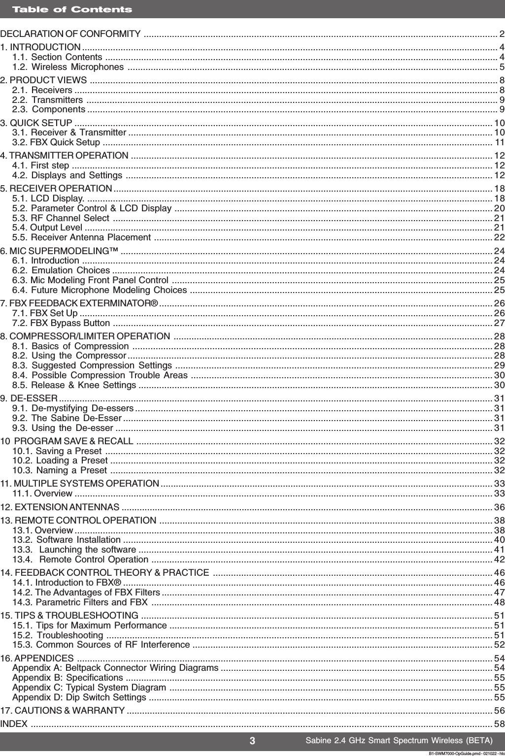
Contents
- 1. users manual 2
- 2. users manual 1a
- 3. users manual 1b
- 4. users manual 1c
- 5. users manual 1d
users manual 1a