SABINE SW70-HD3 Handheld Microphone User Manual B1 SWM7000 OpGuide pmd
Sabine, Inc. Handheld Microphone B1 SWM7000 OpGuide pmd
SABINE >
Contents
- 1. users manual 2
- 2. users manual 1a
- 3. users manual 1b
- 4. users manual 1c
- 5. users manual 1d
users manual 1c
38
Sabine 2.4 GHz Smart Spectrum Wireless (BETA)
Multiple Systems Operation
13. REMOTE CONTROL OPERATION
13.1. Overview
In many circumstances you will adjust and control your Sabine
SWM7000 wireless microphone system using the front panel controls,
as outlined in previous sections of this operating guide. In circum-
stances where an enhanced level of control over a single receiver is
desired, or to enable simultaneous computer-based control of multiple
receivers, you will need to install (on either a laptop or desktop com-
puter) the free Sabine SWM Remote Control Software Software included
with your system. Only receivers may be remotely controlled; handheld
and belt pack transmitters cannot be remotely controlled.
For online instructions for any function in the software, you may also
refer to the Help menu.
13.1.1. Single Receiver vs. Multiple Receiver
Remote Control
All SWM7000 series receivers have an RS-232 jack on the back for
serial connection to your computer. Thus, any single receiver can be
controlled remotely. Control over multiple receivers from a single com-
puter is possible only for ND-series (SW51ND-R and SW52ND-R) re-
ceivers. These units have additional RS-485 network connections (RJ-
45 jacks) for daisy-chain connection from one receiver to the next. Up
to 35 receivers (70 transmission channels if all receivers are 2-channel)
may be connected in this network, all under the control of a single
computer. Single and dual channel receivers can be mixed in the same
network. The first receiver in such a network can be connected to the
computer via an RS-232 or RS-485 serial cable; the remaining units will
then be connected via RS-485.
It is not possible to upgrade/retrofit a standard receiver to make it an
ND-series unit.
13.1.2 Features & Controls Added by SWM
Remote Software
All front panel controls and displays are duplicated in the software. In
addition, a deeper level of software control over receiver operation is
enabled. These new controls are complete and independent for each
transmission/reception channel, meaning there are two sets of con-
trols for dual channel receivers. These controls and displays include:
•Parametric filter access and control. FBX filters can be changed
to parametric filters, and their width, depth, and frequency can be
adjusted. Changes can be made at any time, both before and after
FBX filters have been set. Parametric and FBX filters can be mixed
in any combination, totaling 12 for each receiver channel.
•Adjustable FBX parameter control. Maximum depth of FBX fil-
ters can be adjusted globally; filter width can be adjusted globally
or individually. Two controls, Sensitivity and Persistence, can be
tweaked to tailor the operation of automatic FBX filter placement to
match the audio program. Proper settings will optimize the bal-
ance between false filtering and delayed response to feedback (the
factory default settings should operate excellently in the vast ma-
jority of conditions and may never need to be changed).
•Control over balance of FBX Fixed and Dynamic filters. Any
FBX filter can be set to be either fixed or dynamic.
Tech Tip
Front Panel Control
LOCK 1 —All front panel controls
are locked.
LOCK 2 —Programmable lock; you
can select which con-
trols are locked.

39 Sabine 2.4 GHz Smart Spectrum Wireless (BETA)
B3-SWM7000-OpGuide.pmd - 021022 - hto
Multiple Systems Operation
•Adjustable high and low cut filters. High Cut Filter, user-control-
lable between 3 KHz and 20 KHz; 12dB/octave roll-off
•Additional compressor controls. Aside from adjustments for
ratio, threshold, and attack (which duplicate front panel controls),
the Remote Software provides control of compressor release time
and knee. The effect of compression on the output signal as a
function of input signal strength and parameter settings is displayed
in Sabine’s unique dynamic ColorComp graph, in addition to the
traditional opposing-meter indicators.
•RF Scan and Report, which measures strength for each of the 70
transmission channels, and displays a hierarchical ordering of the
clearest, strongest channels to use during system setup and op-
eration. You can print a copy of the scan results.
•Additional memory options. In addition to saving presets in re-
ceiver memory, channel configuration settings can be saved to and
recalled from disc or hard drive. All parameter settings made with
the remote control, including adjustments that are not accessible
from front panel controls (e.g., compressor knee and release), are
saved with presets. All software settings stored for each of the 15
presets, including settings not accessible from the front panel, will
be loaded whether presets are recalled by remote control or from
the front panel. Note that all settings made in Off-line/Edit mode
can be saved and applied in online operation..
•Ability to print a report of all parameter settings, creating hard
copy documentation.
•A receiver channel output mute button.
•The ability to custom name each RF channel and receiver. This
name will be displayed in both software operation, and on the re-
ceiver front panel.
•Display of important transmitter status information. In addi-
tion to duplicating the battery charge status, battery warning mes-
sage, and transmitter on/off/mute status from the front panel dis-
play, the Remote Software displays the type of battery in use, the
number of hours the battery has been in use, the frequency mid-
point (in GHz) of the transmission channel chosen, the transmitter
pad and low cut filter settings, and a warning indication in the case
of low RF signal strength. For handheld transmitters, the software
display also shows the type of mic capsule in use.
•Improved and expanded operational displays. In addition to
organizing all front panel displays on a single computer screen, the
Remote Software also displays the exact frequency, width, and
depth of FBX filters. The frequency response curve resulting from
combined filter settings (including FBX, parametric, and high and
low cut) is graphically displayed in the software. Frequency re-
sponse changes imposed by choosing various microphone models
are also shown.
•Customizable front panel lock settings. Software control allows
you to program selective access to front panel controls to be made
available once the Remote Control is disconnected. Customizable
front panel lock settings are saved and recalled as part of each
receiver’s settings. All software-only accessible settings are saved
with presets. Careful programming enables some powerful opera-
tional features — for example, locking Program Save but enabling
other front panel controls (including Program Load) will let front

40
Sabine 2.4 GHz Smart Spectrum Wireless (BETA)
Remote Control Operation
panel users update settings temporarily, yet reload the original set-
tings at the push of a button. Such a temporary adjustment would
not permanently alter a setup designed to work in most situations,
but would allow tweaking to address unusual situations.
13.1.3. Multiple Unit Control by Remote Software
The true extent of the power of the SWM Remote Software is realized
when it is used to control multiple wireless receivers. When ND-series
receivers are connected in a network, the additional controls offered by
the Remote Software over the entire system include:
•Simultaneous multiple channel/system monitoring. The Re-
mote Software “All Channel View” (figure 13g) shows all important
status conditions for up to 50 transmission channels. Color-coded
warnings and alerts draw attention to potential problems.
•Detailed, quick access to a single set of controls. The “Com-
mand View” (figure 13c) displays comprehensive information about
a single selected RF channel, and easy adjustment of all its con-
trols. Command View channel is selected by clicking the appropri-
ate All Channel View button. (NOTE: Each channel display in the
All Channel View also allows quick access to parameter adjust-
ments, by using the right mouse button to popup a parameter con-
trol menu.)
•Quick, interactive control of wireless network channels. All or
selected parameter settings for a given channel can be copied to
one or more additional channels, using the Copy Parameters op-
tion.
13.2. Software Installation
13.2.1. System Requirements/Recommendations
•PC computer equipped with Pentium processor 100 MHz or faster
•Hard disc with at least 10 MB of available space for program files.
•Windows 95 or higher.
•SVGA or greater resolution graphic card and monitor.
•Recommended minimum monitor resolution: 1024 x 768 pixels (or
800 x 600 pixels for 15 inch monitors). Select “small fonts” and 16
bit color as defaults for monitor display.
•One COM port for a serial connection, with a 16550 or faster COM
chip.
13.2.2. Connections
There are two types of connections that are used in a remote controlled
Sabine SWM7000 system:
•For connecting from the serial port on your computer to either a
single receiver, or to the first unit in a multiple receiver system, use
a cable with standard 9-pin D-connectors (male on one end, female
on the other). This plugs into the RS-232 jack on the receiver rear
panel. One connection is all that is necessary even if the receiver
is a 2-channel unit.
NOTE: for connections using a USB connector, a USB to RS-232
adaptor is necessary (see Appendix).
•For connecting to additional (ND-series only) receivers (beyond the
first unit) in a multiple receiver system, use cable adhering to RS-
41 Sabine 2.4 GHz Smart Spectrum Wireless (BETA)
B3-SWM7000-OpGuide.pmd - 021022 - hto
485 standards, with RJ-45 connectors on either end. There are two
such jacks on the back of all ND-series receivers. Either jack can
connect to another receiver either “upstream” or “downstream” from
the computer remote control. As signals travel in both directions
(from computer to receiver and back), it is not necessary to con-
nect the last receiver in a network back to the computer (you do
not need to make a “loop”). Up to 35 two-channel (or one-channel,
or any combination) receivers (up to 70 transmission channels)
can be connected in a single network.
13.2.3. Installing the Software
Follow these simple instructions for installing the Sabine SWM Re-
mote Software on your computer:
1. Start Windows 95 or higher.
2. Insert the Sabine software CD into your PC’s CD ROM drive and
wait a few seconds for the auto-start software installer to open.
Select the SWM7000 Remote Control Software installation icon
and follow the instructions given in the dialog boxes that appear.
NOTE: For best results, allow the installation program to install the
software within the default directories. If you choose to install in
other than the default directories, be sure to remember program
storage location.
13.3. Launching the software
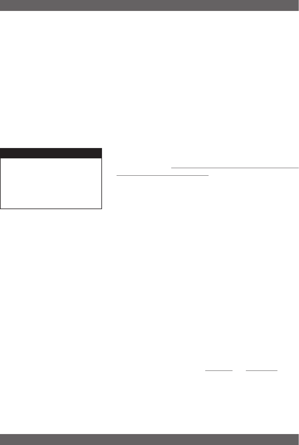
Launching the software produces the Startup Screen (Fig. 13a).
13.3.1. Off-Line Edit/Demo
Clicking the right button (“Off-Line Edit/Demo”) will open the
main software screen regardless of whether any SWM re-
ceivers are connected. The software functions in Off-Line
mode are completely programmable, and may be saved and
downloaded to a connected receiver at a later time. Display
settings (e.g., level, compression, transmitter settings) which
are dependent on the presence of actual signal are simu-
lated, for demonstration only. You may turn the simulated
displays on or off using the OPTIONS menu.
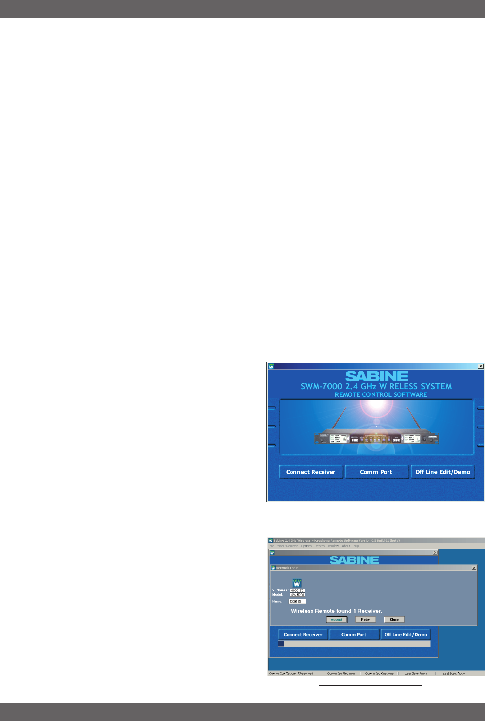
13.3.2. Connecting Receivers.
Clicking “Connect Receiver” will direct the software to poll
the bus on the designated COMM port to detect connected,
powered-on receivers. If no receivers are detected, you
may change the designated COMM port by clicking the
appropriate button. If this also proves ineffective, check
your cables and connections, and make sure the connected
receivers are powered on. In very rare instances you may
need to reset your COMM port settings on your computer.
Once polling is completed, the software will display all the
receivers detected, in sequence, and the model of each
receiver (ND series or standard; 1 or 2-channel). (See fig-
ure 13b for a sample opening display)
Once you confirm that the information reported is correct,
proceed to the main screen, and you may begin remote
control operation.
Fig. 13a Control Software Startup window
Remote Control Operation
Fig. 13b - Connection Screen
42
Sabine 2.4 GHz Smart Spectrum Wireless (BETA)
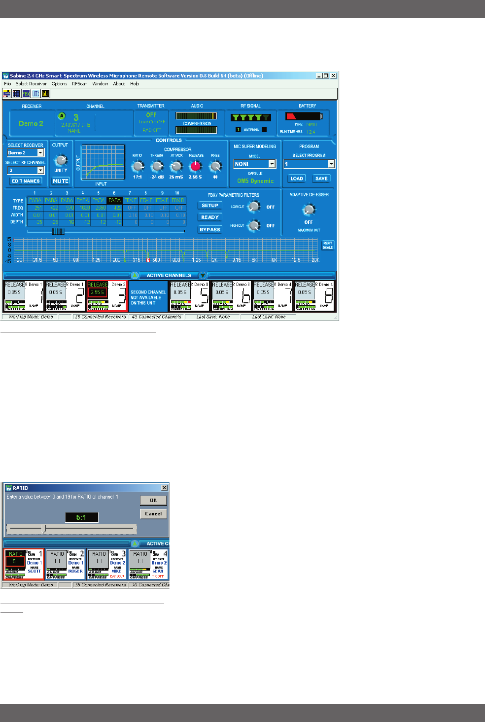
13.4. Remote Control Operation
13.4.1. Two Views, Two Sets of Controls
The default main screen appears
as shown in figure 13c.
The top portion of the screen
(above the “Active Channels” bar
and two arrow buttons) is the
Command View, showing details
and allowing parameter adjust-
ments for a single receiver chan-
nel at a time.
The bottom portion (below “Ac-
tive Channels”) is the All Chan-
nel View, capable of simulta-
neously showing the most im-
portant (but less detailed) infor-
mation for multiple channels.
Each audio (RF) channel in the
system has its own display box,
arranged in rows of eight chan-
nels each, organized in order to
correspond to the string of receiv-
ers in the serial bus.
If you have 8 or fewer RF chan-
nels, both View Modes will fit on
your monitor. For more than 8 channels, there are quick shortcuts for
optimizing your display and switching and mixing View Modes:
•Click and drag the Active Channel bar to pull the All Channel View
up or down, partially or completely covering the Command View.
You cursor will change to a hand icon.
•Use the up/down arrows flanking “Active Channel” to scroll the rows
displayed in the space allocated to the All Channel View.
•Click on the Command View or All Channel View button in the
upper left menu bar (or use F2 and F3), to immediately change
from one to the other.
•To select a channel to edit in either view, left click on a channel in
All Channel View (indicated by a red border around the selected
channel). This displays that channel’s settings in the Command
View. A right mouse click on a single channel shown in the All
Channel View pops up a menu of parameters. The value of the
parameter selected is displayed in the All Channel View for each
RF channel, and also pops up an adjustment screen for the se-
lected channel. You can review and compare settings on all chan-
nels, one parameter at a time, and adjust any setting on any unit
from the All Channel View.
•Parameter adjustments in the Command View can be made by
clicking and turning any knob; or by a right-clicking on a parameter
to pop up an adjustment window, and keying in a value.
Fig. 13c - Control Software Command View
Remote Control Operation
Fig. 13d - All Channel View (with right click on
Ratio).
43 Sabine 2.4 GHz Smart Spectrum Wireless (BETA)
B3-SWM7000-OpGuide.pmd - 021022 - hto
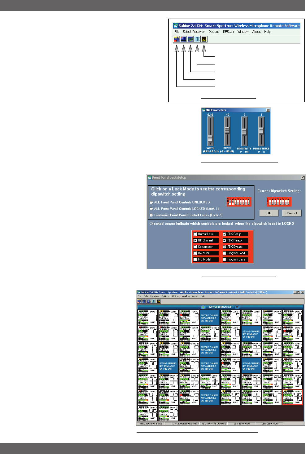
13.4.2. Menus and Icons
Quick access to the features described above, plus some
additional software control, is available from four pull-down
menus (File, Select Receiver, Options, and RF Scan) and
five icons (FBX, Lock, Command View, All Channel View,
and RF Scan) at the top of the screen. The controls asso-
ciated with the five icons can also be accessed using func-
tion keys F2 through F6, respectively. Figure 13e shows
the location of the menus and icons, and describes asso-
ciated controls which are accessed.
13.4.2.1. FBX Settings (F6)
Allows global settings of FBX filter width and maximum
allowed FBX filter depth. As filters are set, they will conform to the
global width chosen at the time of setting. It is thus possible to mix
filter widths by changing the width value in between setting FBX
filters. Maximum depth will be common to all FBX filters, and the
value will update if the global setting is changed.
Sensitivity and Persistence are controls that allow the speed and
analysis of the FBX algorithm to match the type of audio program.
Some audio programs, notably certain types of
classical music, produce occasional waveforms
that are difficult to distinguish from acoustic feed-
back. The factory default Sensitivity and Per-
sistence values should work in almost all con-
ditions; however, you may change them if nec-
essary to prevent the possibility of triggering a
false filter, or to more quickly set the FBX fil-
ters. There is a trade off between speed of filter
placement and how carefully the filter is placed.
More demanding audio sources may require
higher Sensitivity & Persistence settings, which
will slightly slow down the speed of filter place-
ment, but decrease any possibility of mistak-
ing program audio for feedback.
13.4.2.2. Lock (F5)2. Lock (F5)
2. Lock (F5)2. Lock (F5)
2. Lock (F5)
You can customize the mix of functions that
will be locked when choosing Front Panel
Lock 2 (figure 13g).
13.4.2.3. All Channel View (F3)13.4.2.3. All Channel View (F3)
13.4.2.3. All Channel View (F3)13.4.2.3. All Channel View (F3)
13.4.2.3. All Channel View (F3)
Shows the All Channel View as a (vertically)
resizable window (figure 13h).
13.4.2.4. Command View (F4)13.4.2.4. Command View (F4)
13.4.2.4. Command View (F4)13.4.2.4. Command View (F4)
13.4.2.4. Command View (F4)
Shows the Command View on the screen (fig-
ure 13c).
Fig. 13h - Active Channels Window - All Channel View
Remote Control Operation
Fie. 13f - FBX Parameters window
FIg. 13g - Front Panel Lock Setup
RF Scan (F6)
Front Panel Lock Control (F5)
Set FBX Parameters (F4)
All Channel View (F3)
Command View (F2)
Fig. 13e Menu Bar Icons
Remote Control Operation
44
Sabine 2.4 GHz Smart Spectrum Wireless (BETA)
13.4.2.5. R13.4.2.5. R
13.4.2.5. R13.4.2.5. R
13.4.2.5. RF Scan (F6)F Scan (F6)
F Scan (F6)F Scan (F6)
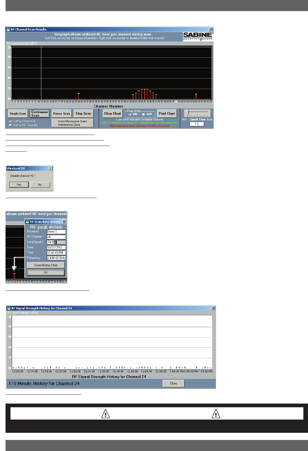
F Scan (F6) Use the RF scan to get a “picture”
of the potential RF interference in
your location. You should perform
a scan before every program so you
can see the ambient RF levels on
all 70 channels of your system.
Caution: The RF Scan mutes and
takes control of the selected re-
ceiver. All other functions are dis-
abled on the selected receiver. Do
not perform an RF scan during
your program!
Select RF Scan by using the
toolbar button, the F6 hot key, or
the RF Scan menu tem. You will see the screen shown in Figure 13i.
Select Single Scan or Continuous scan if you want to look at the RF
levels over time. The software will take control of the selected receiver,
and will step through all 70 channels. You can control the speed of the
scan using the Dwell Time adjustment.
Scan results are shown in several ways. A green line indicates a Sabine
transmitter is active on the associated channel. A red line indicates
ambient RF is present on the channel, at a level indicated by the scale
on the left side of the chart. A dotted red line indicates a previous RF
level from an earlier scan, and a small yellow “T” indicates the peak RF
level observed over the entire time. Left click on any line brings up a
window allowing you to disable the specific channel (figure 13J). If you
chose Continuous Scan you can also choose to see the Channel De-
tails (figure 13k) and a history of all RF activity on a particular channel
for the duration of the Continuous scan (figure 13L).
Channels with very low RF signals (below -70 dBm) should be consid-
ered open channels. We include this low level measurement so you
can see the activity in your location, but the Sabine transmitters will
overpower and ignore those very low signals.
Fig. 13L RF Scan Channel History
Remote Control Operation
Fig. 13i RF Scanner results: one Sabine
Transmitter (will display as a green line) and
some low-level RF interference (will display as
red lines)
Fig. 13k RF Scan Channel Information
RF Scan CAUTION
Do not perform an RF scan during your program!
Fig. 13J Delete Channel confirmation box