SABINE SW70-HD3 Handheld Microphone User Manual B1 SWM7000 OpGuide pmd
Sabine, Inc. Handheld Microphone B1 SWM7000 OpGuide pmd
SABINE >
Contents
- 1. users manual 2
- 2. users manual 1a
- 3. users manual 1b
- 4. users manual 1c
- 5. users manual 1d
users manual 1b

30
Sabine 2.4 GHz Smart Spectrum Wireless (BETA)
8.3.3. Bass Guitar Settings
Bass players use a variety of techniques, often in the same song, that
can benefit from compression. Compressing bass evens out peaks
and keeps the bass level in the mix.
Ratio: set to 4:1
Thresh: set to compress peaks only
Attack: quick attack, medium release, hard knee; (try various re-
lease settings, depending on the speed of notes played)
Gain: output boosted slightly
8.4. Possible Compression Trouble Areas
Like any signal processing, compression can be misused, and im-
proper application may cause undesirable side effects in the audio sig-
nal. Some of these problems include:
1. Noise. If the threshold for compression is set too low, and the
output gain is raised substantially to make up for the gain loss of
compression, the resulting output signal can be noisy. This is
because the overall signal must be raised significantly to produce
the same audible level, and the noise floor of your equipment will
be amplified unnecessarily. This problem will be exaggerated if the
input signal level to the compressor is very low (which will already
degrade the signal-to-noise ratio).
2. Breathing. In situations where the compression ratio is high, the
threshold is low, and the release time of the compressor is short,
the noise floor will modulate up and down as the audio signal rises
above and falls below the threshold.
3. Over-compression. Applying too much compression to a mix
can sometimes result in such evened-out dynamics that the “life”
of the music or speech has been removed or curtailed. Dynamic
variation may be a major component of a performer’s message and
command of the audience; don’t remove dynamics, just control
them. This may be particularly true for percussive musical instru-
ments such as drums.
8.5. Release & Knee Settings
Two other important compressor variables are
release time
and
knee
.
Release time adjusts the speed with which compression stops and
output gain returns to unity with input gain, once the input signal falls
below the compression threshold. Knee refers to the degree with which
the full ratio of compression is imposed once the input level threshold is
approached and exceeded. A “hard knee” changes from no compres-
sion to maximum compression exactly and immediately at the thresh-
old crossing; a “soft knee” gradually imposes the full compression ratio
as the input gain approaches and exceeds the threshold. In Sabine
products, the “softness” of a knee can vary from 1-40, with the higher
level representing the “softest” character. In such a setting, slight com-
pression will begin well below the compression threshold, increase as
the input gain crosses the threshold, and reach full compression well
above the nominal threshold.
Values for release time and knee are set at the factory: default release
time is 400 mSec, and the default knee setting is a “soft” setting of 20.
These defaults can be temporarily changed or reprogrammed using the
Sabine True MobilityTM Remote Software (see Section 13 for details).
Compressor Limiter
31 Sabine 2.4 GHz Smart Spectrum Wireless (BETA)
B2-SWM7000-OpGuide.pmd - 021022 - hto
9. DE-ESSER
9.1. De-mystifying De-essers
Certain consonant sounds produced by the human voice contain more
energy than others, and have the potential to overload a microphone
capsule. This can produce a disproportionately harsh result when
amplified through a sound system, and/or recorded to analog or digital
storage media. The most common and obvious of these sounds (in
English and many languages) is the “ssss” sound, associated with
pronunciation of both “s” and soft “c” consonants, also the consonants
“t,” “f,” “x” and sometimes “d.” The technical term for this particular
vocal sound is “sibilance,” and the devices that control such sounds
are typically called “de-essers” (or sometimes sibilance controllers).
The frequency range of sibilance will vary depending on the singer/
speaker, the consonant involved, the orientation to the microphone, the
microphone itself, and the normal variations in human vocalization.
Cardioid- pattern condenser microphones are especially susceptible to
sibilance problems, but the problem can also occur with other types
and patterns of microphones. The range of frequencies affected by
sibilance starts above 2 KHz, and generally tapers off above 10 KHz; in
other words, sibilance is primarily a problem associated with higher
frequencies (though not the upper octave of human hearing).
9.2. The Sabine De-Esser
The Sabine De-Esser is essentially a type of frequency-band compres-
sor, active in the 2-10 KHz range, and inactive below 2KHz and above
10 KHz. Sabine’s algorithm works by dynamically comparing band-
specific and associated harmonic energy levels to the total signal en-
ergy. When spikes are detected that correspond to sibilance, a shelv-
ing filter is imposed on the appropriate frequency bands, and remains
in place only for the duration of the sibilance. High frequency energy
levels that remain below the comparison threshold do not trigger de-
essing, and lows and highs outside the sibilance range are also passed
unprocessed and unaffected. This means the Sabine De-Esser is ef-
fective but transparent.
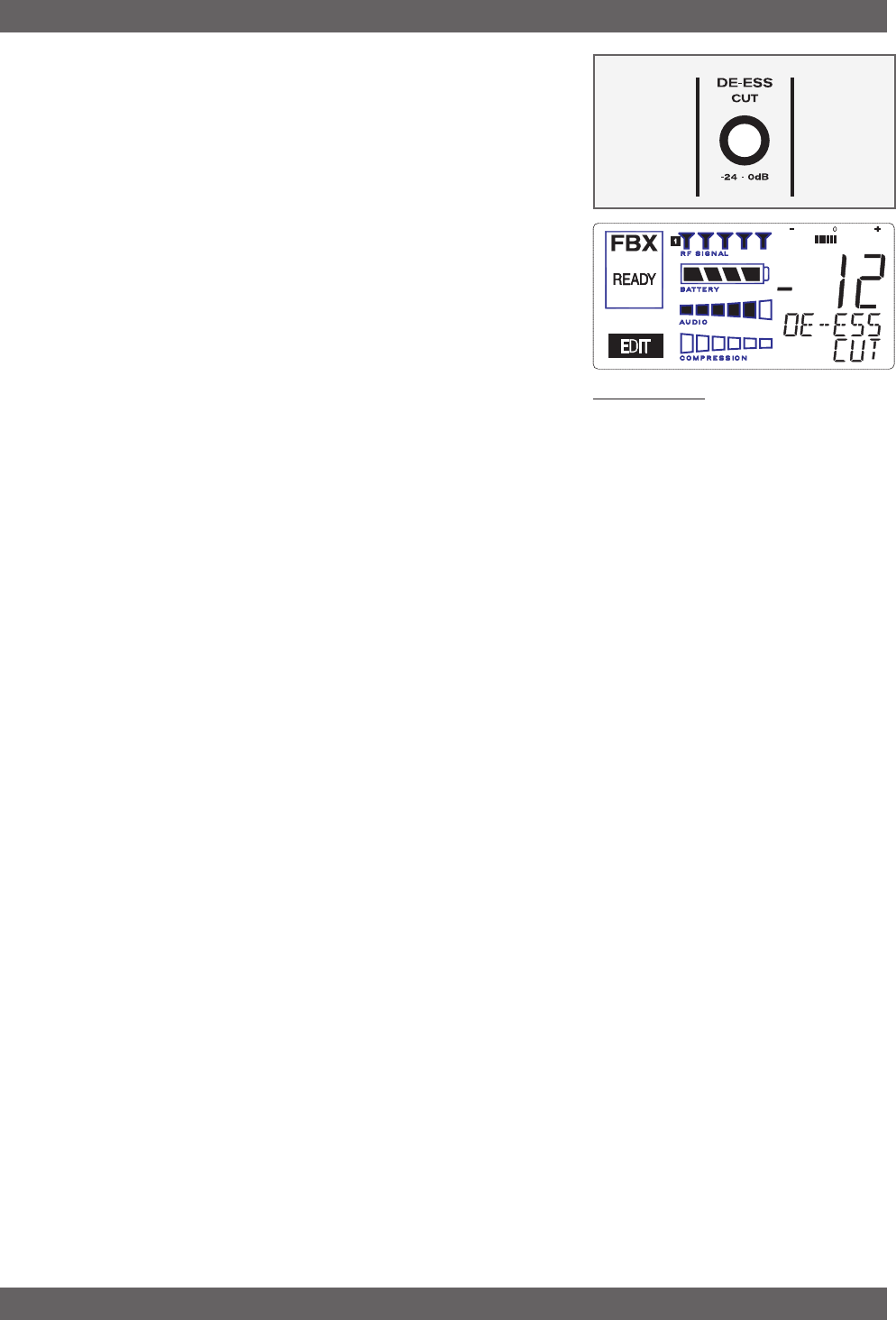
9.3. Using the De-esser
Using the Sabine De-Esser is simplicity itself. Turning the knob la-
beled “DE-ESS CUT” counter-clockwise will increase the amount of
sibilance reduction, by increasing the maximum depth of the shelving
filter. The maximum allowable cut is 24 dB.
Fig. 9a: De-esser
De-esser
32
Sabine 2.4 GHz Smart Spectrum Wireless (BETA)
Fig. 10b
10 PROGRAM SAVE & RECALL
Most wireless microphone systems provide control of one or two set-
tings (RF channel and maybe gain). With so little to remember, the
ability to save and recall system settings has not been necessary.
With the Sabine SWM7000 series, however, you get a very sophisti-
cated processor with a variety of adjustable parameters. The ability to
save and recall your carefully programmed setups can be a tremen-
dous time-saver. Your SWM7000 allows you to store and recall up to
15 different presets.
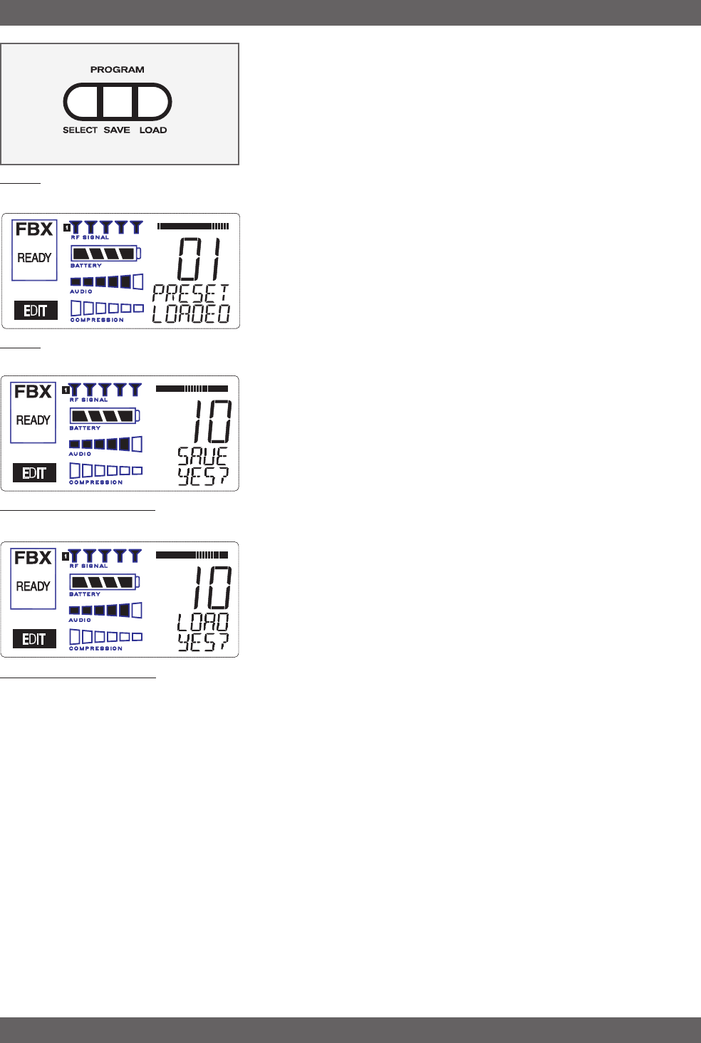
10.1. Saving a Preset
To save a program, press the SELECT button. The next available loca-
tion (numbered 00 - 15) will be shown in the LCD Display. If you want to
replace an existing program, press SELECT until you reach that
program’s number. Then press the SAVE button. The function display
will show “YES?”. If you are ready to save, immediately press the
SAVE button again, and your settings will be saved to that program
number. The message SAVED will be shown for four seconds in the
text display to confirm this action, as the LCD Display continues to
show the number (00-09) of the preset. After four seconds, the LCD
Display will revert to an indication of the RF channel.
10.2. Loading a Preset
Loading a program is just as easy. Press SELECT until you locate the
program number you wish to load. Press LOAD. The function display
will show “YES?”. Immediately press the LOAD button again and your
new program, including all the parameters, will be loaded for that chan-
nel. The message LOADED will appear in confirmation.
10.3. Naming a Preset
Presets, channels and receivers can be named using the Sabine True
Mobility Remote Software. Refer to Section 14 for details.
Program Save & Recall
Fig. 10b
Fig. 10b: Program SAVE YES?
Fig. 10b: Program LOAD YES?

33 Sabine 2.4 GHz Smart Spectrum Wireless (BETA)
B3-SWM7000-OpGuide.pmd - 021022 - hto
Multiple Systems Operation
11. MULTIPLE SYSTEMS OPERATION
11.1. Overview
In many circumstances a single wireless microphone system is all
that will be in use at any one time. Larger applications (church, con-
cert hall, theater stage, conference room, etc), however, can often re-
quire a large array of wireless microphones, all demanding flawless
uninterrupted simultaneous operation.
Multiple system operation presents at least two important operational
challenges: interference among transmission channels, and setup com-
plexity. The Sabine SWM7000 provides powerful solutions to both,
particularly the interference problems associated with two or more RF
channels at work at the same time, at the same location.
11.1.1. Multiple System Interference
Sabine’s SWM7000 addresses multiple system interference with two
strategies. First, greater available bandwidth in the 2.4-2.4835 GHz
range means more channels can occupy the band, i.e., the expanded
range can be divided into a greater number of separate transmission/
reception bands. Second, with Smart Spectrum transmission and re-
ception, channels are more tolerant of interference. The net result is
that the SWM7000 offers the potential for many more simultaneous
transmission channels than conventional UHF or VHF systems.
While such performance benefits are one of the major advantages of
the SWM7000, more systems working at the same time leads to a
greater potential for complexity. Fortunately, the SWM7000 also offers
tools to simplify setup and operation.
11.1.2. Setup Complexity
Multiple wireless systems in a large installation are of course more
complicated than a single transmitter/receiver. More space is needed,
and the sheer quantity of transmitters and receivers that may be in use
at a single installation can prove difficult to manage. The SWM7000
series helps manage such potential complexity with four strategies
and/or system accessories:
1. First, the SW72 and SW72-NDR receivers offer a 50% space-sav-
ing advantage with 2-channel receivers that occupy the same 1U
space as single channel receivers. Each channel in a 2-channel
system shares the true diversity operation of the two antennas
connected to the single receiver chassis.
2. Second, the optional SWA6SS (six-system antenna distribution
amplifier) greatly reduces the complexities of multiple receiver an-
tenna deployment. Since each receiver has two (diversity) anten-
nas, which can be mounted on either the rear or front panel, mul-
tiple receivers at one location can potentially create a forest of
antennas protruding from the front or back of a rack. The SWA6SS
Antenna Distributor reduces the number of antennas to as few as
1/6 what would otherwise be needed. An added important advan-
tage of using the SWA6SS is its distributed signal boost provided
to all the antenna outputs, delivered while maintaining diversity in
all attached reception channels.
34
Sabine 2.4 GHz Smart Spectrum Wireless (BETA)
Multiple Systems Operation
3. Third, large installations often entail long distances from transmit-
ters to receivers, or the presence of obstacles (walls, for example)
in the transmission path that can interfere with clear reception.
While the SWM7000 series is designed to minimize these kinds of
problems without accessories, the SWASS-EXT (set of two exten-
sion antennas, shown in figure 12b on next page) may prove helpful
or even necessary in some situations. In addition to providing re-
mote and/or desirable low profile positioning with improved recep-
tion, the SWASS-EXT also adds another 18 dB of antenna gain for
even more reliable system performance. The Extension Antenna
and Distribution Amplifier components are also designed to oper-
ate in tandem, with the Extension Antenna plugged directly into
the amp, which can then feed (via cable) the antenna inputs of 6
receivers. A combination of 2-channel receivers (SW72-R or SW72-
NDR), a set (2 pieces) of SWASS-EXT, and one SWA6SS, would
reduce the antenna clutter of 12 transmission channels to a single
pair of extension antennas. (See section 12 for more information
about setup and use of the SWASS-EXT).
4. Fourth, software control for the ND series receivers allows up to 70
receiver channels to be controlled from a single computer. This
quick and powerful control methodology means you can monitor
and change transmission channels, mic modeling, compression
and de-essing — in short, all front panel controls — from a remote
laptop or desktop. In addition to simplifying multiple unit operation
with remote front panel controls, the remote software provides ad-
ditional features and functions not available from front panel con-
trol. (See Section 13 for more information about setup and use of
the Remote Software).
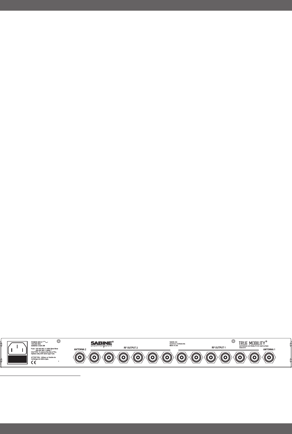
11.1.2.1. SWA6SS Antenna Distribution Amplifier
Sabine’s optional accessory SWA6SS Antenna Distribution Amplifier
is ideal for simplifying antenna set up when multiple receivers are used,
by using a single pair of antennas to replace pairs for up to 6 different
receivers. Standard equipment packed with each Antenna Distributor
includes an AC power cable, and 6 pairs of 1-meter long jumper cables
(RG-58 AU foam core) for connecting the Antenna Distributor to receiv-
ers (2 cables provide true diversity reception to each receiver).
For best results, the Antenna Distribution Amplifier should be positioned
close enough to the receivers to minimize cable runs. In most applica-
tions, you can use the standard Sabine 2.4 GHz antennas supplied
with any of the receivers to connect to the terminals on the Antenna
Distributor, and then connect (in matching pairs) the jumpers to all your
receiver antenna connections (up to 6 receivers, 1 pair per receiver).
Care should be exercised when using longer cables, due to possible
transmission signal loss (approximately 1.7 dB/meter). Using the “rule-
of-thumb” that a signal loss no greater than 6 dB will prove acceptable
in many circumstances, you may be able to use RG-58 cable up to 3
meters or so in length. However, a better strategy than moving the
Fig. 12a SWA6SS Antanna Distributor

35 Sabine 2.4 GHz Smart Spectrum Wireless (BETA)
B3-SWM7000-OpGuide.pmd - 021022 - hto
Multiple Systems Operation
Antenna Distributor to a better position, and risking excessive trans-
mission loss back to the receivers or requiring an upgrade to more
expensive cable, is to utilize a pair of Sabine Extension Antennas
(SWASS-EXT Kit). These will connect to the antenna inputs of the
Antenna Distributor, and offer increased range; better rear-source RF
rejection; an expanded 180 degree forward sensitivity; flexible mount-
ing options; and signal boost (see Section 12).
For more details regarding specifications and operation of the SWA6SS
Antenna Distribution Amplifier, please refer to the operating guide in-
cluded with that product.
Mounting Receiver Antennas: These should be mounted so they face
the transmitters. For example, if the antennas are mounted on the rear
of the receiver, then the back of the receiver should face the transmit-
ters. Use the optional SWA700 Front-to-Rear antenna mounting kit to
mount the antennas on the front of the receiver if necessary.
Stacking Receivers: Avoid stacking receivers with antennas mounted
to each one. Antennas from various receivers in close proximity can
increase the likelihood for interference. Mount your receivers with at
least QQQ space between them, or use the SW6SS Antenna Distribu-
tion Amplifier to rout the signal from one pair of antennas to up to six
receivers.
Extension Antennas: If the receivers must be mounted a so they
cannot "see" the transmitters, then use the SWASS-EXT Extension
Antennas (sold as a pair) in a position that allows a line of sight be-
tween transmitters and the antennas. The SWASS-EXT provide the
following benefits:
•Wall mount or mic-stand mount
•Straight and right angle TNC connectors
•1800 reception pattern
•+18 dB boost in RF
•Matched pairs
•Wood-tone finish
•Phantom-powered from either the receiver or the distribution amp
Antenna Distribution: For best results when using many receivers in
one location use the SWA6SS Antenna Distribution Amplifier. The RF
signal from one pair of antennas can be routed to up to 6 receivers, or
12 channels. This improves RF performance because the interaction
from many receiver antennas is eliminated, and you get a much "cleaner"
looking installation. Each SWA6SS comes with the cables to rout the
signal from the distribution amp to the receivers. For best RF perfor-
mance use the Extension Antennas with the distribution amp rather
than the standard receiver antennas.
36
Sabine 2.4 GHz Smart Spectrum Wireless (BETA)
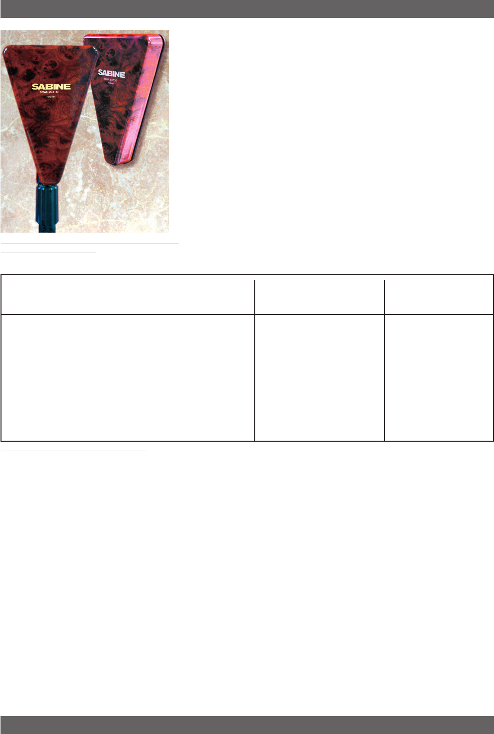
12. EXTENSION ANTENNAS
Sabine’s SWM7000 series receivers are designed for easy interface
with Sabine’s SWA-SSEXT Extension Antenna Kit (figure 12b). This
triangular, attractive wood-grained unit is designed to mount easily and
unobtrusively on a wall (allowing either a through-the-wall or out-the-
bottom connection), or (by threading) atop a microphone stand for a
more portable or temporary positioning. Each package contains 2 Ex-
tension Antennas, all necessary mounting hardware (screws and mic
stand thread connectors), both right-angle and straight connectors for
mating with RG-58 cable (for connections to a receiver or Antenna Dis-
tribution Amplifier), and an adapter to allow connection to thicker, less
lossy cables such as RG-8 (which allow a greater cable run from an-
tenna to receiver).
While an extension antenna affords the opportunity to increase the
distance from transmitter to receiver, there is a loss of signal in the
interconnecting cable that limits that distance. The maximum connec-
tion length is determined by the type of cable used, and the degree of
signal attenuation acceptable.
Cable TypeBelden # Insulation Center Conductor 900 MHz 1.8 GHz 2.4 GHz 900 MHz 1.8 GHz 2.4 GHz
RG58 9203 Polyethelene #20 Stranded -10.00 -14.35 -16.29 22 15 14
RG58/AU 9311 Foam Polyethelyne #20 Stranded -7.64 -9.88 -11.10 29 22 20
RG212/U 9861 Polyethelene #15.5 solid, -3.83 -5.34 -6.11 57 41 36
silver plated
RG8/U 9913 semi-solid Polyethelyne #10 solid -1.40 -2.00 -2.50 157 110 88
RG142 83242 Teflon #18 solid, -4.10 -5.72 -6.54 54 38 34
silver plated
10 Meter Attenuation Maximum Practical
Distance Using SWASS-EXT
(in meters)
Coaxial Cable Attenuation Table
Fig. 12c Coaxial Cable Attenuation Table
Let’s presume that an acceptable degree of loss over the total cable
run is 6 dB. Without external signal boosts, the different cables shown
in the table would then allow maximum lengths ranging from less than
4 M (RG-58) to 24 M (RG8/U). Thus, for a passive extension antenna,
your choices are to limit the cable run, or increase your budget and buy
the more expensive, thicker cable.
Fortunately, Sabine’s SWASS-EXT Active Extension Antenna offers a
far better, more cost-effective solution, due to its built-in active 18 dB
signal boost. In the case of low-cost RG-58 cable, adding an SWASS-
EXT to your setup increases the acceptable maximum cable run by
more than 4 times, to 14 meters. With RG-8 cable, the maximum
length is extended to 88 meters!
Power for the Extension Antenna is delivered from any Sabine SWM7000
series receiver or SWA6SS Antenna Distribution Amplifier (see Section
11).
An additional advantage of using Sabine’s SWASS-EXT Extension An-
tenna stems from its more focused, directional nature. Sabine receiver’s
coaxial dipole antennas (standard equipment that mount directly on
the front or rear panels of the receiver or SWA6SS) are more omni-
directional in nature. In contrast, the Sabine’s Extension Antenna is
Extension Antennas
Fig. 12b SWASS-EXT Mic-stand mount and wall-
mount extension antennas

37 Sabine 2.4 GHz Smart Spectrum Wireless (BETA)
B3-SWM7000-OpGuide.pmd - 021022 - hto
sensitive to RF reception in a 180-degree arc in front of its mounted
position. It extends sensitivity to the front and off-axis side locations
as it increases rear RF rejection.
The multiple functions (relocation of antenna, boost of signal, direc-
tional sensitivity) of Sabine’s Extension Antenna mean there are many
applications in which its addition to your system can greatly enhance
performance. Here’s a short list of such applications:
1. Antenna repositioning. Provides solutions when receiver place-
ment options are limited or challenging. Sabine’s Extension
Antenna’s multiple mounting options allow higher placement (wall
mount or microphone stand mount).
2. Barriers interrupting transmission. Anytime a barrier interferes
with transmission and reception, Sabine’s SWA-SSEXT can be
mounted on the transmitter side of the barrier with cable connec-
tions made on the receiver side. Perhaps the most common situ-
ation of this nature would arise when receiver and transmitter are
located in separate rooms.
3. Expanded or directional sensitivity required. Sabine’s Exten-
sion Antenna picks up in a 180-degree arc, focused towards the
front. Reception in this arc is enhanced.
4. Rear RF rejection required. Because Sabine’s Extension An-
tenna is less sensitive to signals received from the rear, it can be
positioned to reject any such directional RF interference.
5. Extended operational range. Given a potential maximum cable
length of almost 100 meters from Extension Antenna to receiver,
Sabine’s SWASS-EXT allows more options for extending the dis-
tance between transmitter and receiver. (It should be noted that
the typical range of Sabine’s SWM7000 series systems without
the Extension Antenna is already 100 meters in typical circum-
stances). Consider that RF signal strength through the air is di-
minished by the square of the distance (twice as far away = ¼ the
signal strength), while signal loss through cable is (roughly) in-
versely proportional (twice as far away = ½ the signal). That means
you can use an extension antenna to replace transmission-through-
air with transmission-through-cable, to help minimize signal loss.
Extension Antennas