Contents
- 1. unsers manual-01
- 2. unsers manual-02
- 3. unsers manual-03
- 4. unsers manual-04
- 5. unsers manual-05
unsers manual-04
Confidential & Proprietary 63/99
If ODU is not connected in the right order, related devices may fail to communicate with
each other or the unit may read wrong information. Given this, you need to connect the unit with
accurate RF Port and Signal Port in a corresponding number.
For unused RF Ports for ODU expansion, make sure to terminate them using SMA Term.
When you put ODU on the top of BIU, it is recommended to install the unit at least 1U
apart from BIU. Heat from BIU climbes up to reach ODU.
5.1.6 Consumption Power of BIU
The table below shows power consumption of BIU:
Part Unit Consumption Power Remark
Shelf
MCDU
MCPU
Common Part
MPSU
7.5 W
MDBU 800PS 12W
MDBU 800PS+900I+Paging 20W
MDBU 850C 12W
MDBU 850C+700PS 19W
MDBU 1900P 20W
MDBU
MDBU AWS-1 12W
BIU supplies power for ODU. Therefore, when you want to calculate total power consumption of
BIU, you need to add power consumption of ODU to the total value.
Power consumption of ODU is given in the later paragraph describing ODU.

Confidential & Proprietary 64/99
5.2 ODU Installation
ODU should be, in any case, put on the top of BIU. This unit gets required power and RF
signals from BIU. The following table shows components of ODU:
No. Unit Description Remark
Shelf Including Main Board, 19”,1U 1EA
RF Cable SMA(F) to SMA(F), 400mm 2EA
Common Part
Signal Cable 2Row(15P_F) to 2Row(15P_M),650mm 1EA
Optional Part DOU Optical Module with 4 Optic Port Up to 2EA to be
inserted
5.2.1 ODU Shelf Installation
ODU is a shelf in around 1U size. Its width is 19” and so this unit should be inserted into a 19”
Standard Rack. ODU should be, in any case, put on the top of BIU. BIU should be distant
around 1U when the unit is installed.
5.2.2 ODU Power Cabling
ODU does not operate independently. The unit should get power from BIU.
When you connect 2-column, 15-pin D-SUB Signal cable from BIU and install DOU, LED on the
front panel is lit. Through this LED, you can check state values of LD and PD of DOU.
5.2.3 ODU Optic Cabling
As optical module shelf, ODU makes electronic-optical conversion of TX signals and then
makes optical-electronic conversion of RX signals. ODU can be equipped with up to two DOUs.
One DOU supports four optical ports and one optical port can be connected with ROU.
Optionally, only optical port 4 can be connected with OEU.
As WDM is installed in DOU, the unit can concurrently send and receive two pieces of
wavelength (TX:1310nm, RX:1550nm) through one optical core. DOU has SC/APC of optical
adaptor type.
Confidential & Proprietary 65/99
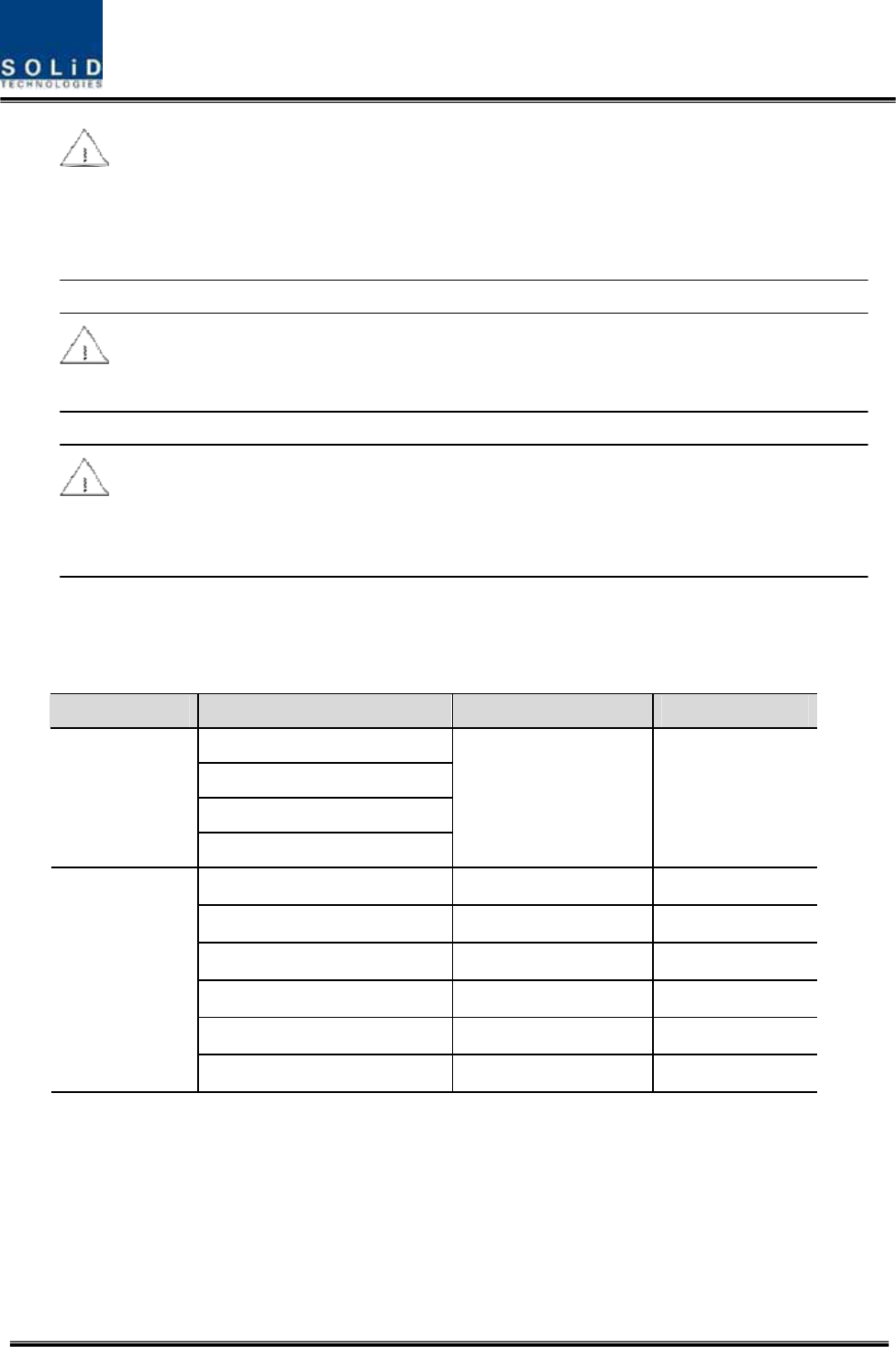
Figure 5.4 – Optical cable of SC/ACP Type
For optical adaptor, SC/APC type should be used. To prevent the optical access part from being
marred with dirt, it should be covered with a cap during move. When devices are connected
through optical cables, you need to clear them using alcohocol to remove dirt.
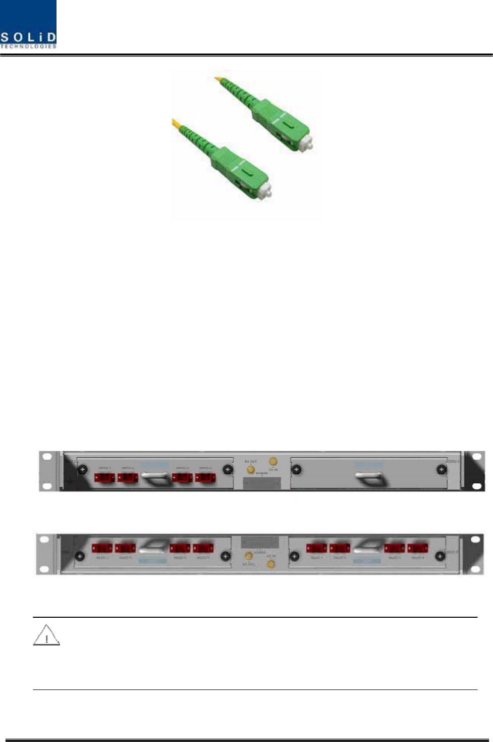
5.2.4 Insert DOU to ODU
In an ODU Shelf, up to two DOUs can be installed. DOU module is in Plug in Play type.
When you insert DOU in ODU, insert the unit into the left DOU1 slot first. You can be careful as
the number is silk printed at the left.
The following figure shows installation diagram of ODU with one DOU inserted in it.
The following figure shows installation diagram of ODU with two DOUs inserted in it.
When you insert DOU into ODU, insert the unit into the left DOU1 slot first. Into unused
slot, you need to insert BLANK UNIT in any case.
Confidential & Proprietary 66/99
5.2.5 Consumption Power of ODU
ODU gets power from BIU. One ODU can be equipped with up to two DOUs. Depending on
how many DOUs are installed, power consumption varies. The table below shows power
consumption of ODU:
Part Unit Consumption Power Remark
ODU_4 DOU 1 EA 13W
ODU_8 DOU 2 EA 26W
5.3 ROU Installation
5.3.1 ROU Enclosure installation
ROU is designed to be water- and dirt-proof. The unit has the structure of One-Body enclosure.
It satisfies water-proof and quake-proof standards equivalent of NEMA4.
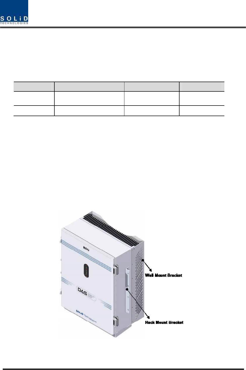
ROU can be mounted into either of a 19” Standard Rack or on a Wall.
Basically, ROU has both of a Wall Mount Bracket and a Rack Mount Bracket.
Depending on the use of the Rack Mount Bracket, the bracket can be removed.
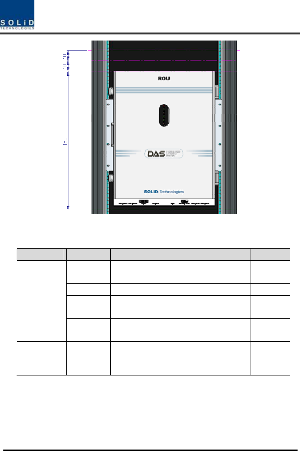
The following shows dimension of the fixing point for the Wall Mount Bracket.
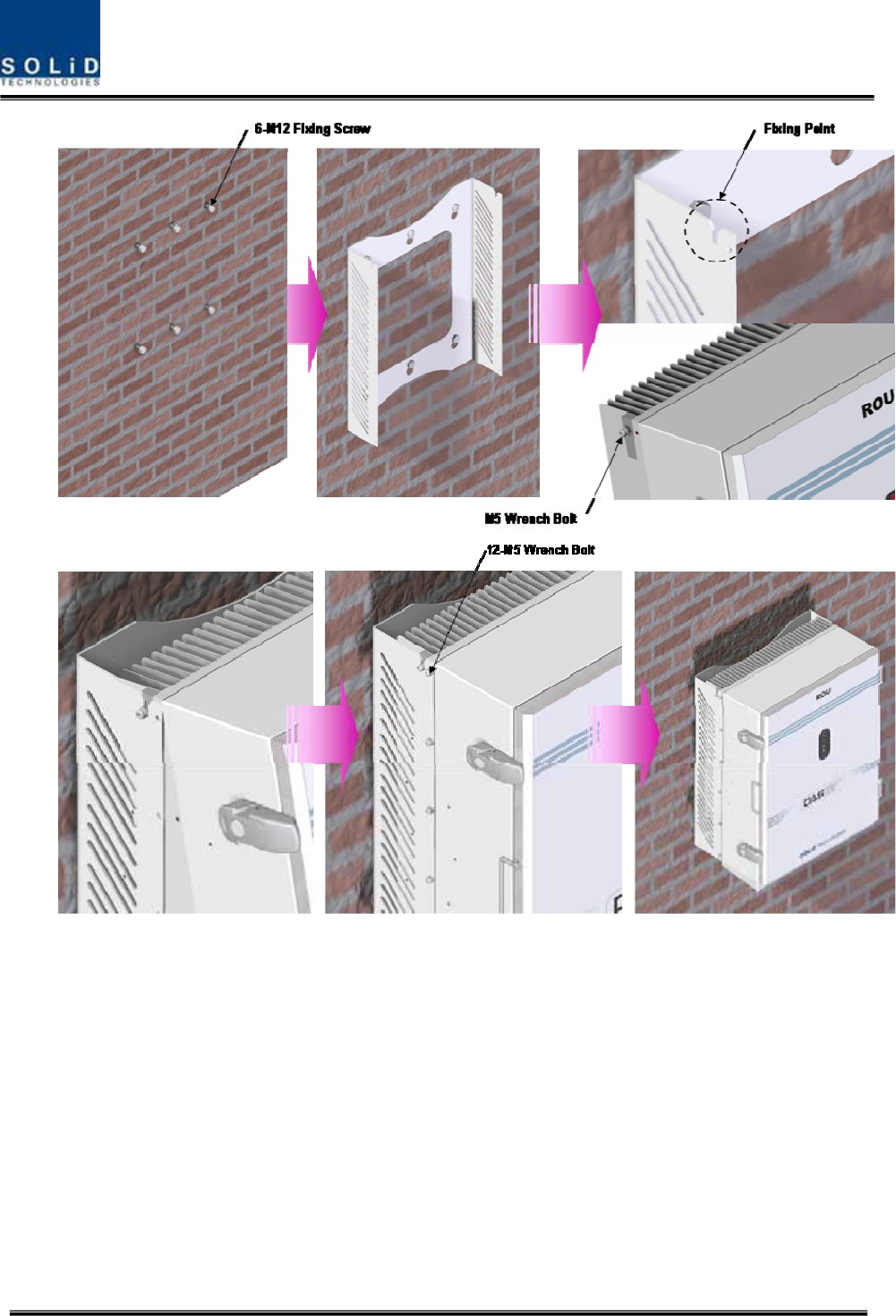
Figure 5.5 – How to install ROU
Confidential & Proprietary 67/99
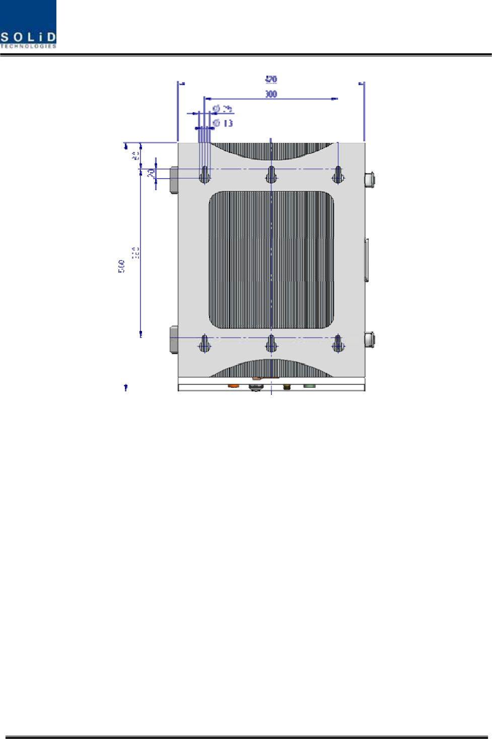
Figure 5.6 – Dimension used to install ROU on the WALL
ROU Wall Mount Installation
Turn M12 Fixing Screws by half on the wall and fully fix the screw with a Wall Mount Bracket on
it.
For convenience, the Wall Mount Bracket has fixing holes to let you easily mount an enclosure.
Turn the M5 Wrench Bolt by half at each side of the Heatsink of the enclosure.
Confidential & Proprietary 68/99
Put the enclosure with the M5 Wrench Bolt fixed on the fixing groove and fix the M5 Wrench
Bolts into the remaining fixing holes.
In this case, you will use 12 M5 Wrench Bolts in total except bolts used for the fixing groove.
ROU Rack Mount Installation
Like other units, ROU is designed to be inserted into a rack. The unit occupies around 13U of
space except cable connection.
Confidential & Proprietary 69/99
ROU component
ROU has the following components:
No. Unit Description Remark
Enclosure Including Rack & Wall cradle 1EA
RCPU - 1EA
R_OPTIC With SC/ACP adaptor 1EA
RPSU Alternative DC-48V or AC 120V 1EA
Multi-Plexer - 1EA
Common Part
Power Cable - MS Connector with 3 hole to AC 120 plug(AC)
- MS Connector with 2 lug termination(DC)
Optional Part RDU+BPF 800PS,800PS+900I+Paging,850C,850C+700PS,
1900P+ AWS-1 RDU, VHF+UHF(NO BPF)
Up to 3EA
to be
inserted
Basically, the common part of ROU should have an enclosure and it is equipped with RCPU to
inquire and control state of each module, R_OPTIC to make both of electronic-optical and
optical-electronic conversions, RPSU to supply power for ROU and a Multi-Plexer to help share
multiple TX/RX signals through one antenna. It should have Power Cable for external rectifier or
to supply required power.
Confidential & Proprietary 70/99
In addition, RDU can be inserted and removed to provide service for desired band (Optional).
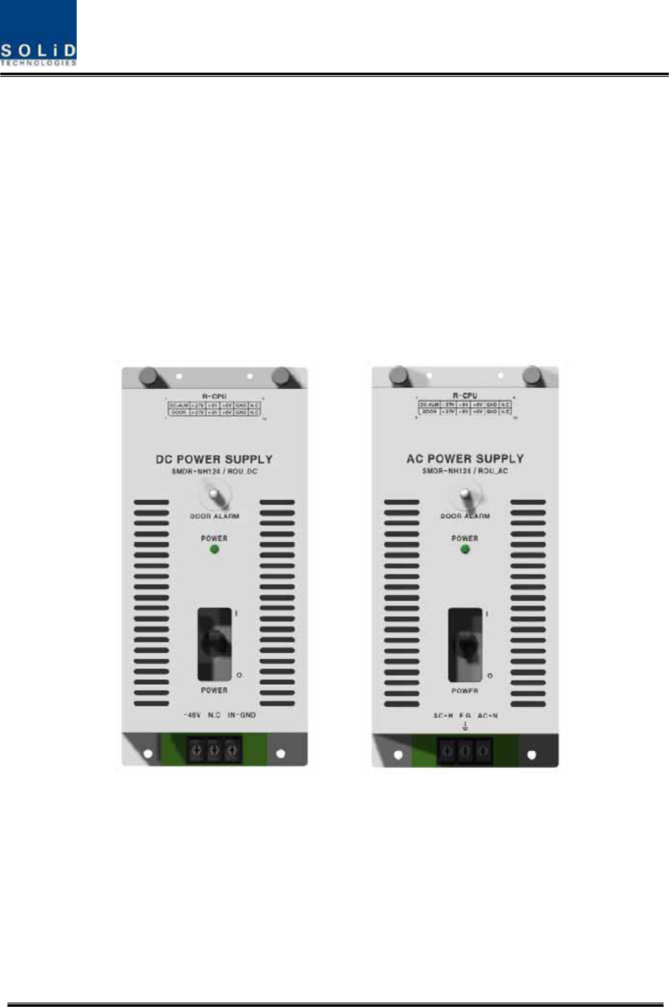
5.3.2 ROU Power Cabling
ROU supports both of DC-48V and AC120V of input power. As RPSU for DC-48 and RPSU for
AC120V are separated from each other, you need to select one of them in case of purchase
order.
RPSU for DC -48V and RSPU for AC 120V have the same configuration and capacity while
each of the units uses different input voltage from each other.
The following figure shows configuration of RPSUs for DC -48V and AC 120V.
Confidential & Proprietary 71/99
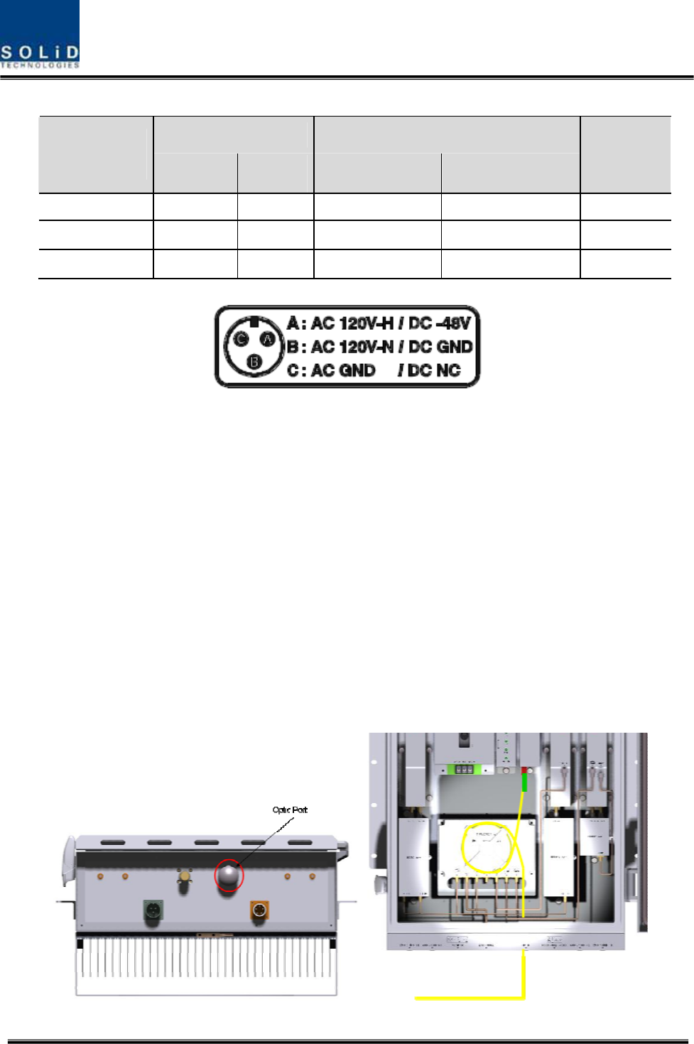
Lug Naming RPSU Terminal naming
MC Connector
numbering AC DC AC DC
Remark
A AC_H -48V AC-H -48V
B AC_N GND AC-N IN_GND
C GND DC NC FG FG
Check if the connection is the same as one seen in the table above and make sure to turn the
power ON.
5.3.3 Optical Cabling
ROU makes optical-electronic conversion of TX signals from upper ODU and OEU and makes
electronic- optical conversion of RX signals. ROU has one optical module in it. As WDM is
installed in the R_OPTIC module, two pieces of wavelength (TX:1310nm, RX:1550nm) can be
sent/received with one optical core at the same time. ROU has SC/APC of optical adaptor type.
For optical adaptor, SC/APC type can be used. To prevent the optical access part from being
marred with dirt, it should be covered with a cap during move. When devices are connected
through optical cables, you need to clear them using alcohocol to remove dirt.
Confidential & Proprietary 72/99
Optical cables should be inserted into Optic Port outside of ROU. Using an optical slack devices
in ROU, you need to coil around one or two roll of cables to be connected with the optical
adaptor of ROPTIC.
At this time, curvature of the optical cable should be at least 10Ø to prevent insertion loss from
being increased.
Through GUI, check if PD value of ROPTIC is in a tolerable range (+4~-1dBm).
5.3.4 Insertion of RDU
ROU has slots to enable up to three RDU modules to be inserted into the unit.
You can insert a RDU into any slot. It is not possible to provide services with a RDU
module alone; you need to connect the module with Cavity BPF in any case.
The table below shows types of RDU and CAVITY BPF:
Multiplexer Interface
No Unit naming Cavity BPF RF CABLE
TX RX
1 RDU 800PS 800PS BPF TX CABLE 1EA
RX CABLE 1EA BPF OUT RDM RX IN
2 RDU 850C 850C BPF TX CABLE 1EA
RX CABLE 1EA
BPF TX
OUT BPF RX IN
3RDU
1900P+AWS-1 1900P DUP TX/RX CABLE 1EA RDM AWS+1900P
5RDU
800PS+900I+PA
800PS+900I+PA
BPF
TX CABLE 1EA
RX CABLE 1EA
RDM TX
OUT RDM RX IN
6RDU
850C+700PS
850C+700PS
BPF
TX CABLE 1EA
RX CABLE 1EA
RDM TX
OUT RDM RX IN
7RDU
VHF+UHF -TX CABLE 1EA
RX CABLE 1EA - -
The following describes how to install RDU in ROU.
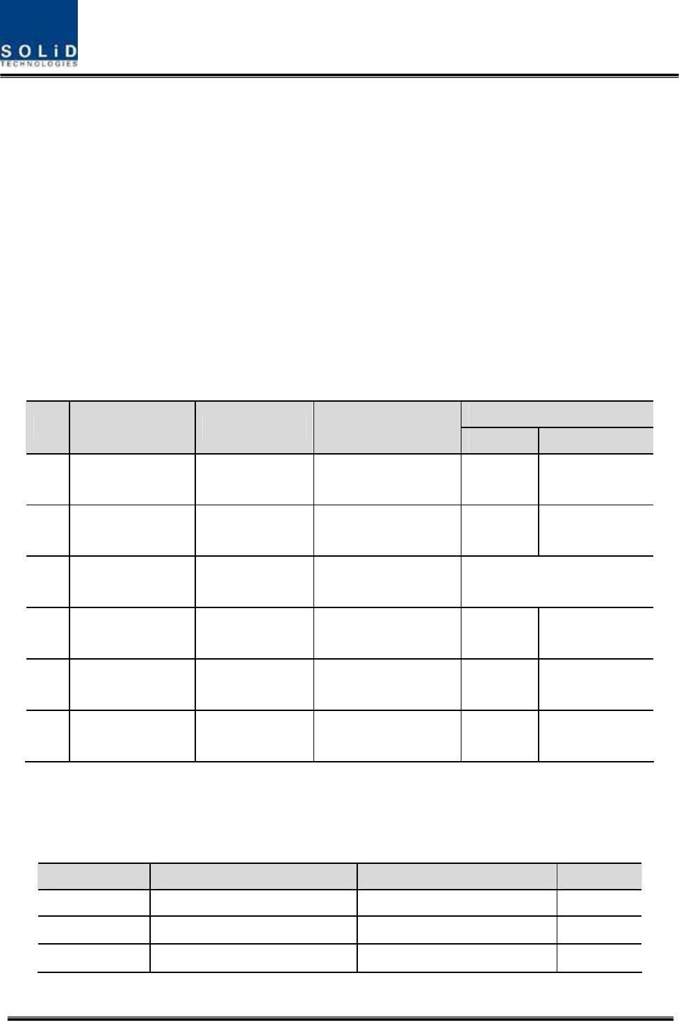
How to install RDU 800PS Ass’y
The following components are required:
No. Unit Description Remark
1 RDU 800PS RF Module
2 800PS BPF BPF
3 800PS TX RF CABLE SMA(M) to SMA(M), 360mm
Confidential & Proprietary 73/99
4 800PS RX RF CABLE SMA(M) to SMA(M), 410mm
Combine ྙRDU 800PS with 800PS BPF (As it is a plug type, push the unit to
combine with BPF.)
Insert the combined 800PS+850C BPF Ass’y into any slot of ROU.ྚ
Combination point of 800PS+800PS BPF Ass’y of the multiplexerྛ
Interface Point
Multiplexer Port naming
800PS RDU 800PS BPF
Remark
800PS+900I+PA TX - TX OUT

Confidential & Proprietary 74/99
800PS+900I+PA RX RX IN -
How to RDU install 850C Ass’y
The following components are required:
No. Unit Description Remark
1 RDU 850C RF Module
2 850C BPF BPF
3 850C TX RF CABLE SMA(M) to SMA(M), 310mm
4 850C RX RF CABLE SMA(M) to SMA(M), 310mm
Combine 850C RDU with 850C BPF (As it is a plug type, push the unit to combine ྙ
with BPF.)
Insert the combined 850C+850C BPF Ass’y into any slot of ROU.ྚ
Combination point of 850C+850C BPF Ass’y of the multiplexerྛ
Interface Point
Multiplexer Port naming
850C RDU 850C BPF
Remark
Confidential & Proprietary 75/99
850C TX - TX OUT
850C RX - RX IN
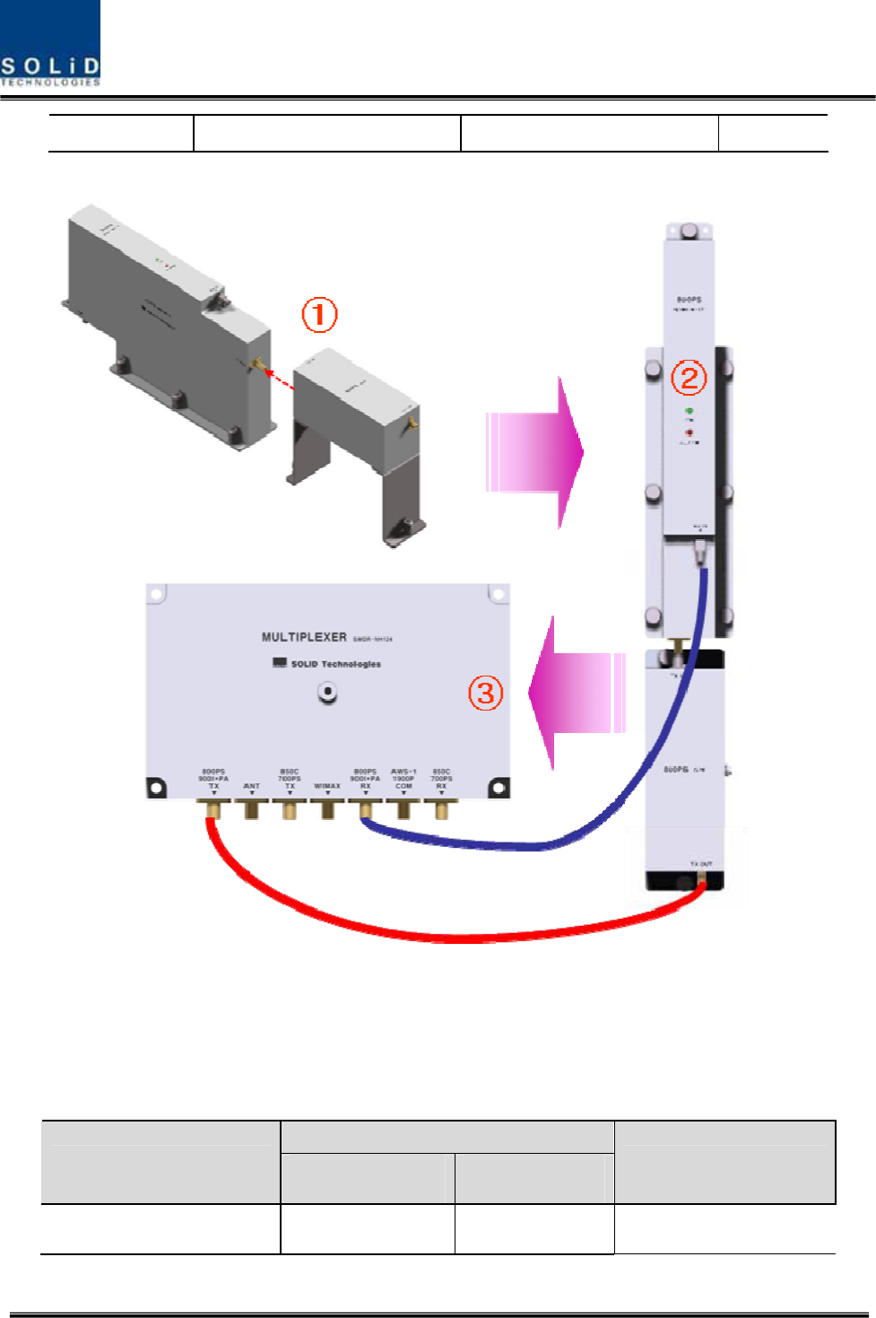
How to install RDU 800PS+900I+PA Ass’y
The following components are required:
No. Unit Description Remark
1 RDU 800PS+900I+PA RF Module
2 800PS+900I+PA BPF BPF
3 800PS+900I+PA TX RF CABLE SMA(M) to SMA(M), 460mm
4 800PS+900I+PA RX RF CABLE SMA(M) to SMA(M), 380mm
Combine ྙRDU 800PS+900I+PA with 800PS+900I+PA BPF (As it is a plug type, push
the unit to combine with BPF.)
Insert the combined ྚ800PS+900I+PA BPF Ass’y into any slot of ROU.
Combination point of ྛ800PS+900I+PA BPF Ass’y of the multiplexer
Confidential & Proprietary 76/99
Interface Point
Multiplexer Port naming
800PS+900I+PA RDU 800PS+900I+PA BPF
Remark
800PS+900I+PA TX TX OUT -
800PS+900I+PA RX RX IN -
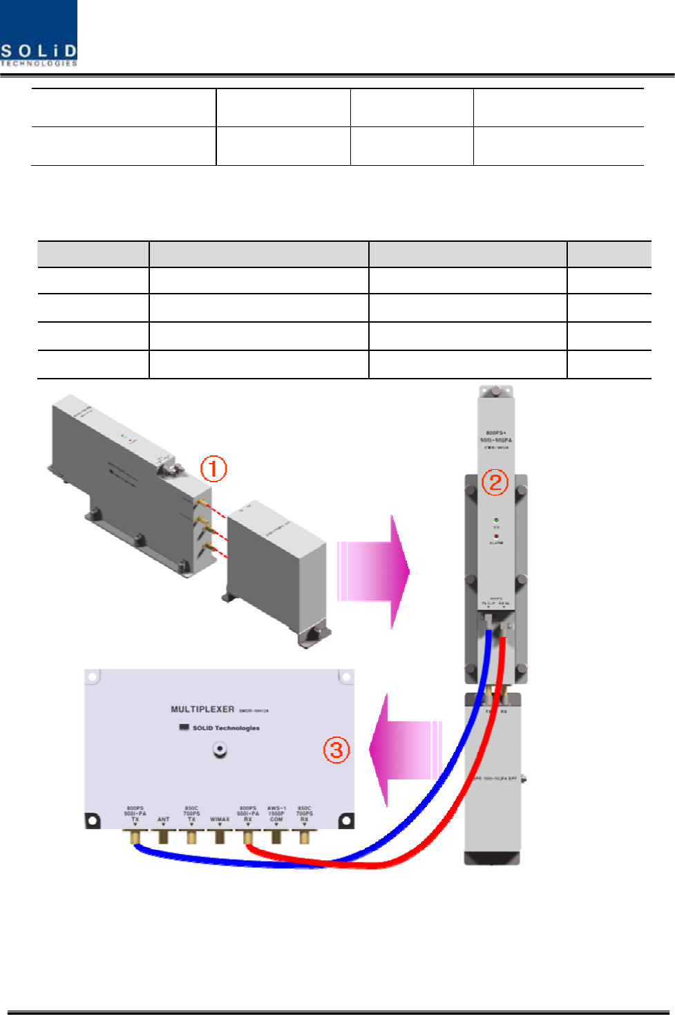
How to install RDU 850C+700PS Ass’y
The following components are required:
No. Unit Description Remark
1 RDU 850C+700PS RF Module
2 850C+700PS BPF BPF
3 850C+700PS TX RF CABLE SMA(M) to SMA(M), 470mm
4 850C+700PS RX RF CABLE SMA(M) to SMA(M), 400mm
Combine ྙRDU 850C+700PS with 850C+700PS BPF (As it is a plug type, push the unit
to combine with BPF.)
Insert the combined ྚ850C+700PS BPF Ass’y into any slot of ROU.
Combination point of ྛ850C+700PS BPF Ass’y of the multiplexer
Confidential & Proprietary 77/99
Interface Point
Multiplexer Port naming
850C+700PS RDU 850C+700PS BPF
Remark
850C+700PS TX TX OUT -
850C+700PS RX RX IN -
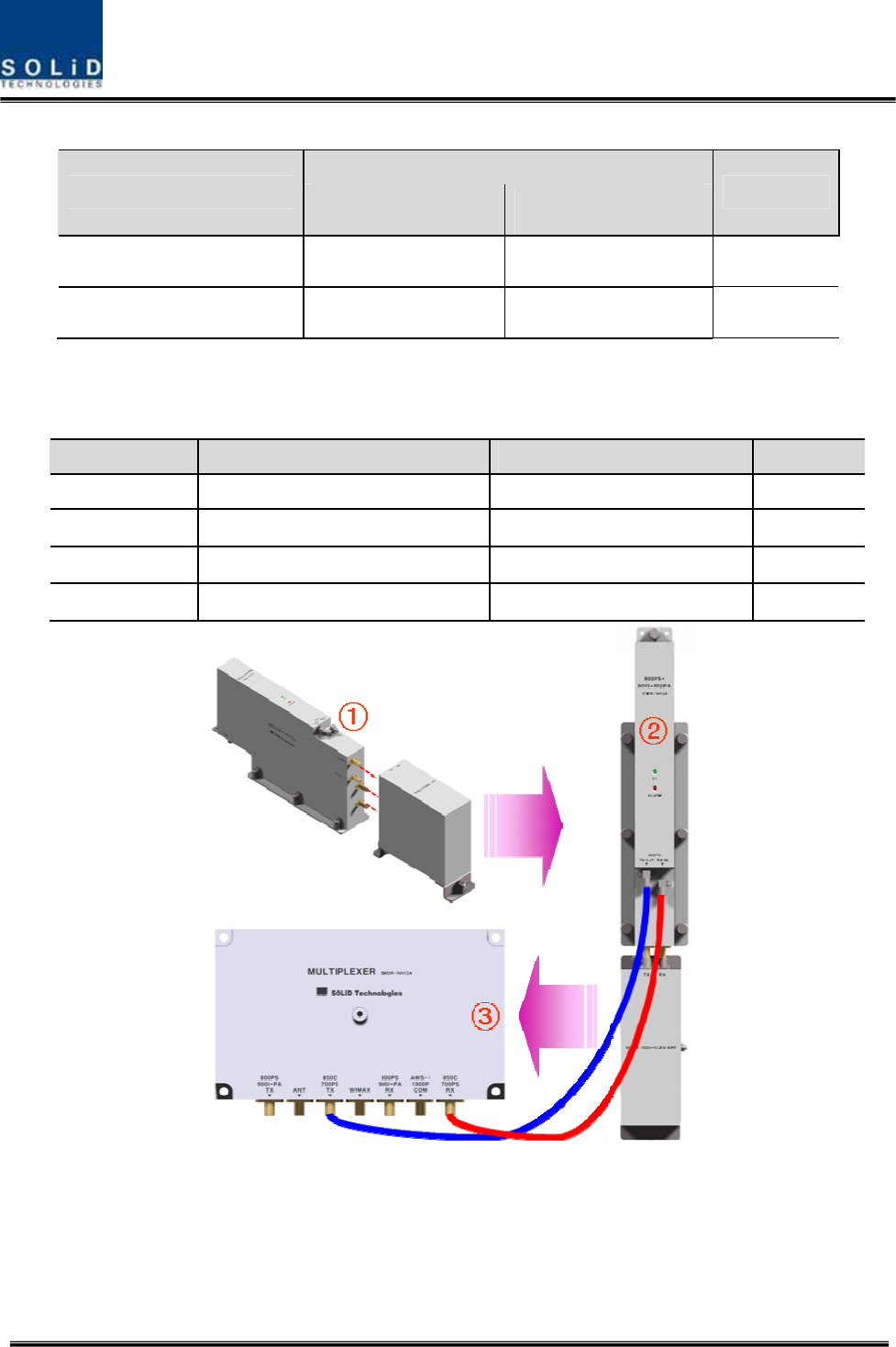
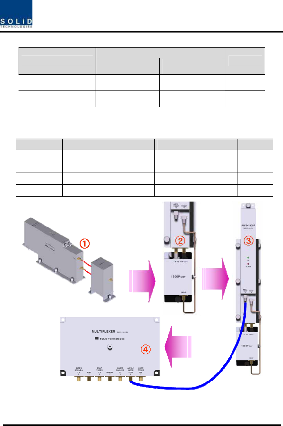
How to install RDU 1900P+AWS-1 Ass’y
The following components are required:
No. Unit Description Remark
1 RDU 1900P+AWS-1 RF Module
2 1900P+AWS-1 BPF BPF
3 1900P+AWS-1 RF CABLE SMA(M) to SMA(M), 390mm
4 1900P+AWS-1 RF-01 SMA(M) to SMA(M) Semirigid
Combine ྙRDU 1900P+AWS-1 with 1900P BPF (As it is a plug type, push the unit to
combine with BPF.)