Sanwa Electronic Instrument Co 90486 2.4GHz Radio Control System User Manual 1
Sanwa Electronic Instrument Co Ltd 2.4GHz Radio Control System 1
Contents
- 1. User Manual-1
- 2. User Manual-2
- 3. User Manual-3
- 4. User Manual-4
- 5. User Manual-5
User Manual-1

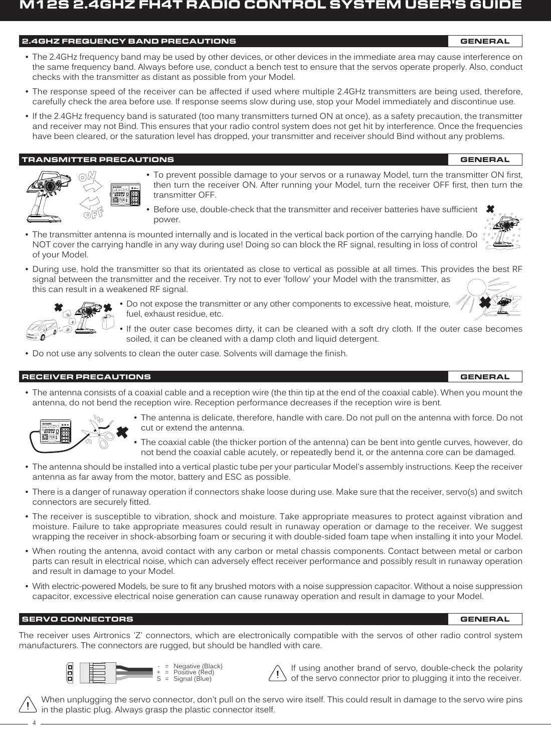
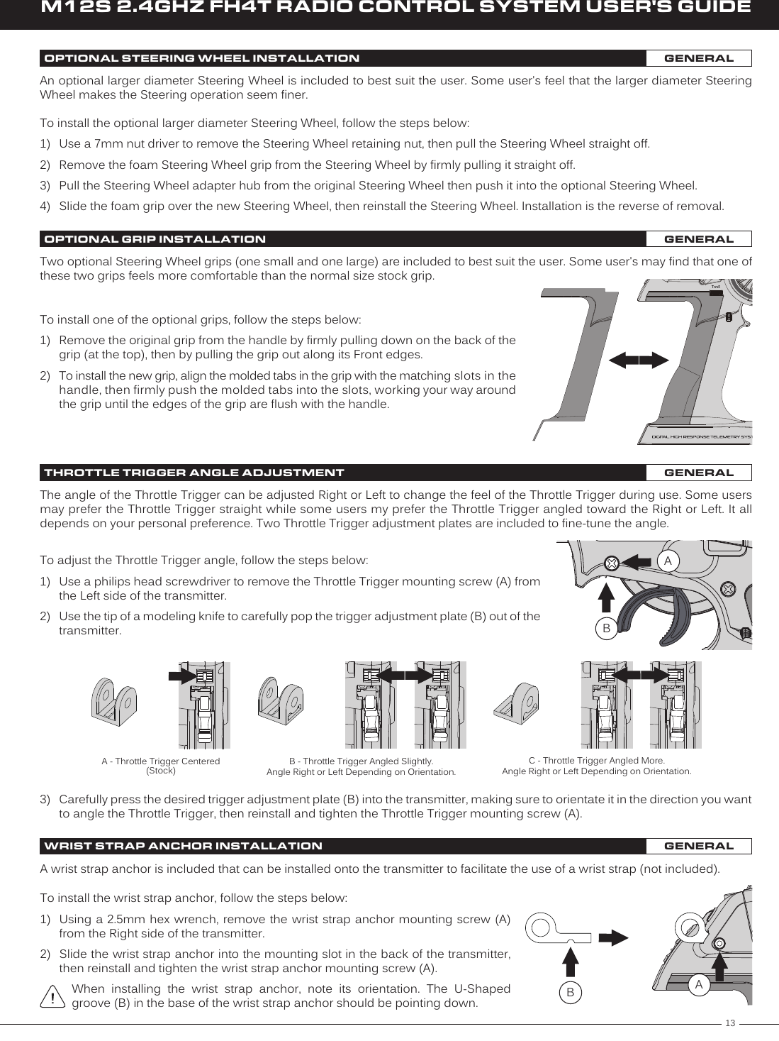
![23M12S 2.4GHZ FH4T RADIO CONTROL SYSTEM USER'S GUIDETR7) Move the Steering Wheel and Throttle Trigger to verify that the servos are operating normally, then repeatedly press theBACK key to return to the STATUS screen.Under some circumstances, the receiver may not operate after turning the transmitter and receiver ON. If this occurs, perform the Binding procedure again.3) Scroll UP or DOWN to highlight the BIND menu, then press the ENTER key toopen the BIND menu.4) While holding down the Bind Button on the receiver, turn the receiver ON. TheBind LED on the receiver will flash slowly. Release the Bind Button. The BindLED on the receiver will continue to flash slowly.The Binding function allows you to Bind the transmitter and receiver pair. When new, it is necessary to pair the transmitter and receiver to prevent interference from transmitters operated by other users. This operation is referred to as 'Binding'. Once the Binding procedure is complete, the setting is remembered even when the transmitter and receiver are turned OFF, therefore, this procedure usually only needs to be done once.The M12S transmitter features a Safety Link function that is used to program a unique code to each receiver/Model pair, preventing the transmitter from controlling a Model that it's not currently programmed for. The Safety Link function is compatible only with FH4 or FH4T receivers. It's not compatible with FH2 or FH3 receivers.Before beginning the Binding procedure, connect the switch harness, servos and the receiver battery to your receiver, using the diagram in the Receiver Overview Diagram, Connections and Mounting section on page 8. Make sure that both the transmitter and the receiver are turned OFF.IMPORTANT: This section details Binding the RX-471 FH4 Super Response receiver with a Safety Link Model number of 1 and with the Servo Operating Mode set to Normal mode. If you are Binding an FH2 or FH3 receiver, or if you prefer to change the Safety Link Number or the Servo Operating Mode, see the BIND Menu section on pages 30 ~ 32.5) Scroll DOWN to highlight the BIND [ENTER] option, then press the ENTER key.The [ENTER] command and LED1 on the transmitter will begin to flash andthe Bind LED on the receiver will flash rapidly, then go out.6) After the Bind LED on the receiver goes out, press the ENTER key a second time. Both the Bind LED on the receiver and LED1 ontransmitter will illuminate solid blue, indicating that the Binding procedure is complete.You must complete step 5 below within 10 seconds or the Bind LED will go out, indicating the receiver has timed out. If this occurs, turn the receiver OFF, then repeat step 4.1) Turn the transmitter ON. The STATUS screen should be displayed.2) Press the SELECT switch to highlight the SYSTEM menu, then press the ENTERkey to open the SYSTEM menu.Double-check that the Modulation is set to FH4T, Telemetry is turned ON, Safety Link is set to 01 and CH1, CH2, CH3 and CH4 are each set to NOR. If you want to change any of these settings, see the BIND Menu section on pages 30 ~ 32.TRANSMITTER AND RECEIVER BINDING GENERAL](https://usermanual.wiki/Sanwa-Electronic-Instrument-Co/90486.User-Manual-1/User-Guide-2587747-Page-24.png)