Sanwa Electronic Instrument Co 90486 2.4GHz Radio Control System User Manual 3
Sanwa Electronic Instrument Co Ltd 2.4GHz Radio Control System 3
Contents
- 1. User Manual-1
- 2. User Manual-2
- 3. User Manual-3
- 4. User Manual-4
- 5. User Manual-5
User Manual-3
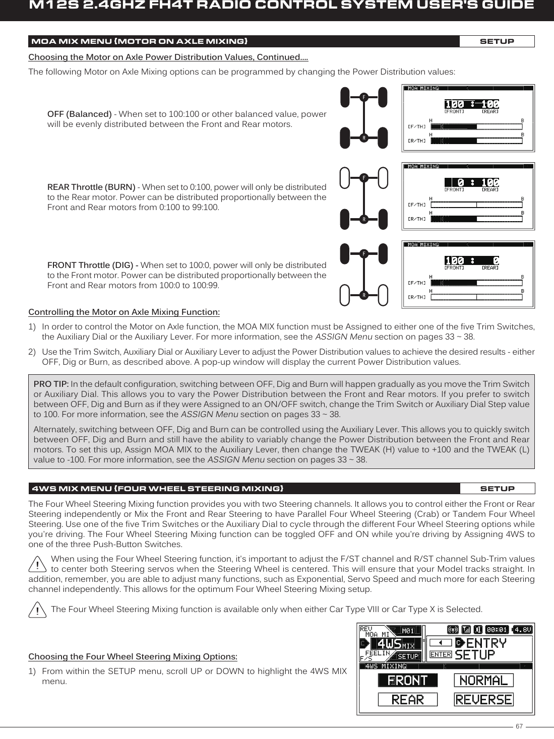
![54M12S 2.4GHZ FH4T RADIO CONTROL SYSTEM USER'S GUIDELOG SETUP MENU {DISPLAY ONLY TELEMETRY OPTIONS}SYSTEM5) Turn your other transmitter ON, then navigate to that transmitter's BIND menu and highlight the [ENTER] option. For more information, refer to your transmitter's User's Guide.4) Press the ENTER key to open the BIND menu. The Bind screen will be displayed and [ENTER] will be highlighted.7) Press the ENTER key on your other transmitter. RECEIVE will flash fast on the M12S transmitter.8) Press the BACK key, first on the M12S transmitter, then on your other transmitter, to complete the Binding process. The Bind LED on your other transmitter should illuminate solid and both LED1 and LED2 on the M12S transmitter should be extinguished. 9) Press the BACK key to return to the STATUS screen, then scroll UP or DOWN to open the TELEMETRY screen. You should now be able to view the other transmitter's Steering and Throttle Output Data on the M12S TELEMETRY screen. In addition, if your other transmitter supports Telemetry,you should be able to view that transmitter's Telemetry Data on the M12S TELEMETRY screen.6) Press the ENTER key on the M12S transmitter to begin the Binding process. SEARCH will flash slowly.Enabling Receiver Mode, Continued....3) Press the ENTER key to open the LOG SETUP menu, then scroll UP or DOWN to highlight the RXMODE menu.Steering and Throttle Output Data Display AdjustmentsThe Steering Point and Throttle Point functions allow you to calibrate the M12S transmitter's TELEMETRY screen ALL page Steer-ing and Throttle Output Data Displays, so the Output Data displayed matches your paired transmitter's Steering Wheel and Throttle Trigger movement.If you don't use the Steering Point and Throttle Point functions to calibrate the Steering and Throttle Output Data Displays, incorrect data will be displayed. These steps should be performed after placing the M12S in Receiver Mode and Binding it to your other transmitter.Calibrating the Steering Output Data Display:1) With the transmitter turned OFF, press and HOLD the DISPLAY key to turn only the Display ON.2) From within the SYSTEM menu, scroll UP or DOWN to highlight the LOG SETUP menu.](https://usermanual.wiki/Sanwa-Electronic-Instrument-Co/90486.User-Manual-3/User-Guide-2587749-Page-8.png)
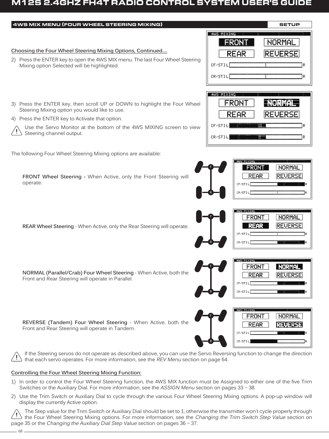
![66M12S 2.4GHZ FH4T RADIO CONTROL SYSTEM USER'S GUIDEPOINT AUX2 MENU {AUXILIARY 2 POINT VALUES}SETUPP1 though P6 setting range is H100 to L100. The default setting for P1 is L100, for P2 is L60, for P3 is L20, for P4 is H20, for P5 is H60 and for P6 is H100. These values are a percentage of Auxiliary 2 servo travel. Changing the Auxiliary 2 Point Values, Continued....3) Scroll UP or DOWN to highlight the desired Point value you would like to change.4) Press the ENTER key, then scroll UP or DOWN to change the Point value. Choosing an H or L value will determine the direction the servo travels.5) Press the ENTER key, then repeat steps 3 and 4 to change any other desired Point values.6) Cycle forward and backward through the Points using the Auxiliary Dial or the Trim Switch you Assigned AUX2 to. You will notice that as you cycle through the Points, the current Point will be highlighted and in addition, the current Point will be displayed in a pop-up window.MOA MIX MENU {MOTOR ON AXLE MIXING}SETUPThe Motor on Axle Mixing function provides you with two Throttle channels. It is typically used for Rock Crawlers and allows you to control either the Front and Rear motors together or independently, giving you Dig and Burn functions. In addition, you can variably change the power distribution between the Front and Rear motors, allowing you the utmost in functionality.Use one of the five Trim Switches, the Auxiliary Dial or the Auxiliary Lever to Activate the Dig and Burn functions while you're driving.When using the Motor on Axle function, it's important to adjust the F/TH channel and R/TH channel Sub-Trim values so both motors are OFF when the Throttle Trigger is in the Neutral Point. In addition, remember, you are able to adjust many functions, such as Exponential, Servo Speed and much more for each Throttle channel independently to allow for the optimum Motor on Axle Mixing setup.The Motor on Axle Mixing function is available only when either Car Type IX or Car Type X is Selected.1) From within the SETUP menu, scroll UP or DOWN to highlight the MOA MIX menu.2) Press the ENTER key to open the MOA MIX menu. 100 [FRONT] : 100 [REAR] will be highlighted.3) Press the ENTER key, then scroll UP or DOWN to change the Power Distribution between the Front and Rear motors. Reducing the [REAR] value will reduce the available power to the Rear motor (Dig) and reducing the [FRONT] value will reduce the power to the Front motor (Burn).Use the Servo Monitor at the bottom of the MOA MIXING screen to view Throttle channel output.Choosing the Motor on Axle Power Distribution Values:You are able to program Dig and Burn functions by changing the Power Distribution between the two motors. When both Front and Rear values are balanced, Dig and Burn functions are Inhibited.](https://usermanual.wiki/Sanwa-Electronic-Instrument-Co/90486.User-Manual-3/User-Guide-2587749-Page-20.png)