Sanwa Electronic Instrument Co 90486 2.4GHz Radio Control System User Manual 3
Sanwa Electronic Instrument Co Ltd 2.4GHz Radio Control System 3
Contents
- 1. User Manual-1
- 2. User Manual-2
- 3. User Manual-3
- 4. User Manual-4
- 5. User Manual-5
User Manual-3
47
M12S 2.4GHZ FH4T RADIO CONTROL SYSTEM USER'S GUIDE
TR
The Low Voltage Alert alarm voltage value cannot be set Lower than the Low Voltage Limit alarm voltage value.
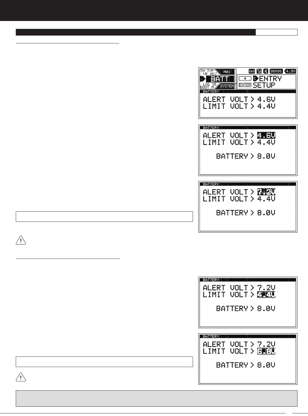
1) From within the SYSTEM menu, scroll UP or DOWN to highlight the BATT
menu.
2) Press the ENTER key to open the BATT menu. ALERT VOLT > 4.6V will be
highlighted and the current transmitter battery voltage will be displayed.
3) Press the ENTER key, then scroll UP or DOWN to choose the desired Low Volt-
age Alert alarm voltage value. We suggest using the value listed in the table
on the previous page that matches the type of transmitter battery you're using.
ALERT VOLT setting range is 4.4V to 9.0V. The default setting is 4.6V.
Changing the Low Voltage Alert Alarm Value:
The Low Voltage Alert alarm will sound to indicate the transmitter batteries are getting low and should be replaced or recharged.
We suggest stopping use as soon as safely possible and replacing or recharging the transmitter batteries. The Low Voltage Alert
alarm will sound for approximately 5 seconds each time the transmitter battery voltage decreases by 0.1 volt. To clear this alarm
before it turns off automatically, press the BACK key or the ENTER key.
BATT MENU {LOW VOLTAGE ALERT AND LIMIT ALARMS}SYSTEM
Changing the Low Voltage Limit Alarm Value:
The Low Voltage Limit alarm will sound to indicate the transmitter batteries are dangerously low and should be replaced or
recharged Right away. The Low Voltage Limit alarm cannot be cancelled. When the Low Voltage Limit alarm sounds, you should
stop use as soon as it's safe, then replace or recharge the transmitter batteries.
WARNING: Continuing to use the transmitter after the Low Voltage Limit alarm sounds can result in loss of control of your
Model. When the Low Voltage Limit alarm sounds, stop use as soon as is safe, then replace or recharge the transmitter batteries.
1) From within the BATT menu, scroll UP or DOWN to highlight LIMIT VOLT > 4.4V.
LIMIT VOLT setting range is 4.0v to 9.0v. The default setting is 4.4V.
2) Press the ENTER key, then scroll UP or DOWN to choose the desired Low
Voltage Limit alarm value. We suggest using the value listed in the table on
the previous page that matches the type of transmitter battery you're using.
The Low Voltage Limit alarm voltage value cannot be set Higher than the
Low Voltage Alert alarm voltage value.
48
M12S 2.4GHZ FH4T RADIO CONTROL SYSTEM USER'S GUIDE
For information about using an optional Telemetry receiver with your M12S transmitter, plugging the Telemetry Sensors into
your receiver and installing them into your Model, see the
Telemetry Connections and Mounting
section on pages 96 ~ 97.
LOG SETUP MENU {TELEMETRY DISPLAY AND RECORDING OPTIONS}SYSTEM
The LOG SETUP menu allows you to turn Telemetry Recording ON and OFF and configure how Telemetry Data is displayed on
the TELEMETRY screen. For example, you are able to change the Telemetry Temperature reading from Fahrenheit to Celsius,
change the values at which the different Telemetry Sensor alarms sound, change how Speed and RPM are displayed and
much more.
In addition, when only the DISPLAY is turned ON using the DISPLAY key, the M12S can be placed in Receiver Mode, allowing it to
Bind with another Airtronics FH3 or FH4T transmitter and read Telemetry Data from it. For example, if using an FH4T transmitter
like the MT-4, MT-4 Telemetry Data can be viewed on the M12S TELEMETRY screen, or, if using an FH3 transmitter like the MX-3X
or M11X that doesn't support Telemetry, Steering and Throttle Output Data can still be viewed on the M12S TELEMETRY screen.
This capability allows the M12S to be used as a separate Telemetry Viewer and Recorder, much like the Airtronics TLS-01
Telemetry Logger.
For information about saving Telemetry Data to a PC, see the
PC
LINK
Menu
section on page 58. For information about using the
TELEMETRY screen and viewing Telemetry Data, see the
TELEMETRY Screen Overview
section on pages 21 ~ 22.
Turning Telemetry Data Recording ON and OFF:
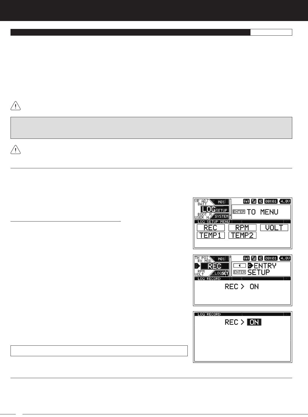
1) From within the SYSTEM menu, scroll UP or DOWN to highlight the LOG SETUP
menu.
2) Press the ENTER key to open the LOG SETUP menu, then scroll UP or DOWN
to highlight the REC menu.
Telemetry Data Recording
The Telemetry Data Recording function records Telemetry Data when the Lap Timer is Started. When the Lap Timer is Stopped,
Telemetry Recording is also Stopped. One Telemetry Data Log is kept in memory at a time and will be available for viewing even
after the transmitter is turned OFF. When the Lap Timer is Started again, the current Telemetry Data Log will be erased and a new
one Started. If you want to Save the current Telemetry Data Log, use the Save Log option in the PCLINK menu.
IMPORTANT: Full Telemetry integration requires the use of an Airtronics RX-461, RX-462 or other Airtronics FH4T Telemetry
receiver (available separately), although Throttle and Steering Output Data can still be viewed on the TELEMETRY screen and
recorded if using an FH2, FH3 or FH4 receiver.
3) Press the ENTER key to open the REC menu. REC > ON will be highlighted.
4) Scroll UP or DOWN to choose the desired Record value, either ON or OFF.
When ON is chosen, Telemetry Data will be Recorded. When OFF is chosen,
Telemetry Data will not be Recorded.
REC setting range is ON or OFF. The default setting is ON.
RPM and Speed Telemetry Data Display Options
The RPM menu allows you to change the way RPM and Speed information is displayed on the TELEMETRY screen ALL and RPM
pages. For example, you can choose to display RPMs, MPH or KM/H. The RPM Gauge and the RPM Digital Display names will
even change from RPM to MPH or KM/H depending on the RPM Unit value chosen. On top of that, you can choose the Maximum
Telemetry Data values that are displayed and the RPM sensor can be calibrated to ensure the most accurate RPM or speed in
MPH or KM/H is displayed for your specific Model.
49
M12S 2.4GHZ FH4T RADIO CONTROL SYSTEM USER'S GUIDE
TR
When you choose UNIT > MPH or UNIT > KM/H the RATIO > value will be replaced with a 10COUNT DIST. > value.
LOG SETUP MENU {TELEMETRY DISPLAY AND RECORDING OPTIONS}SYSTEM
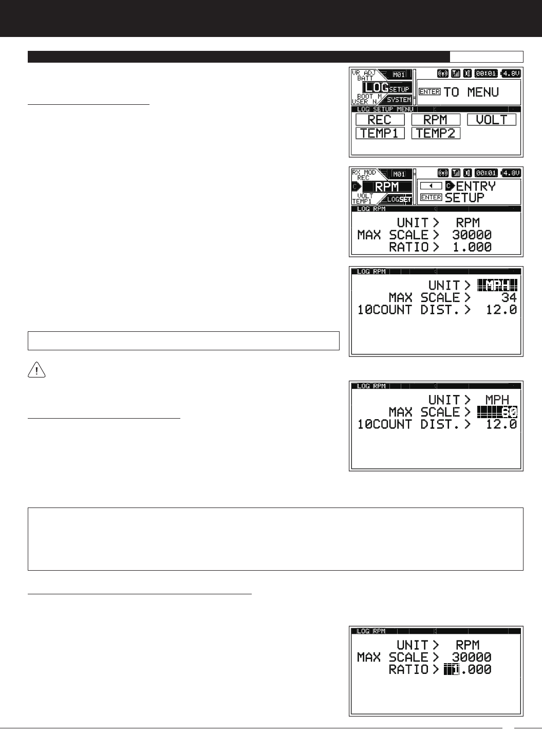
2) Press the ENTER key to open the LOG SETUP menu, then scroll UP or DOWN
to highlight the RPM menu.
UNIT setting range is RPM, MPH and KM/H. The default setting is RPM.
3) Press the ENTER key to open the RPM menu. UNIT > RPM will be highlighted.
4) Press the ENTER Key, then scroll UP or DOWN to change the RPM Unit to the
desired value. When RPM is chosen, the RPM of whatever the RPM Sensor is
attached to will be displayed. When MPH or KM/H is chosen, the speed of your
Model will be displayed in either MPH or KM/H, respectively.
Changing the RPM Unit Value:
1) From within the SYSTEM menu, scroll UP or DOWN to highlight the LOG SETUP
menu.
Changing the Maximum Scale Value:
1) From within the RPM menu, scroll UP or DOWN to highlight the MAX SCALE >
value. This value will vary depending on the UNIT > value chosen previously.
MAX SCALE setting range is 500 to 127500 RPM, 1 to 999 MPH and 1 to 999 KM/H. The default setting is 30000 RPM, 34 MPH
and 54 KM/H.
The Maximum Scale MPH and KM/H setting range will vary based on the 10Count Distance value programmed when you
calibrate the RPM Sensor. For more information, see the
Calibrating the RPM Sensor - Changing the 10Count Distance Value
section on page 50.
Calibrating the RPM Sensor - Changing the Ratio Value:
The Ratio value can be changed if you've Selected UNIT > RPM. By changing the Ratio value you are able to read actual motor or
engine RPM even though the RPM sensor may be mounted to your Model's spur gear and not to the motor's pinion gear or the
engine's flywheel.
1) From within the RPM menu and with UNIT > RPM Selected, scroll UP or
DOWN to highlight RATIO > 1.000.
2) Press the ENTER key, then scroll UP or DOWN to change the Maximum Scale value. This value determines the maximum
RPM, MPH or KM/H value that will be displayed on the TELEMETRY screen ALL and RPM pages.
50
M12S 2.4GHZ FH4T RADIO CONTROL SYSTEM USER'S GUIDE
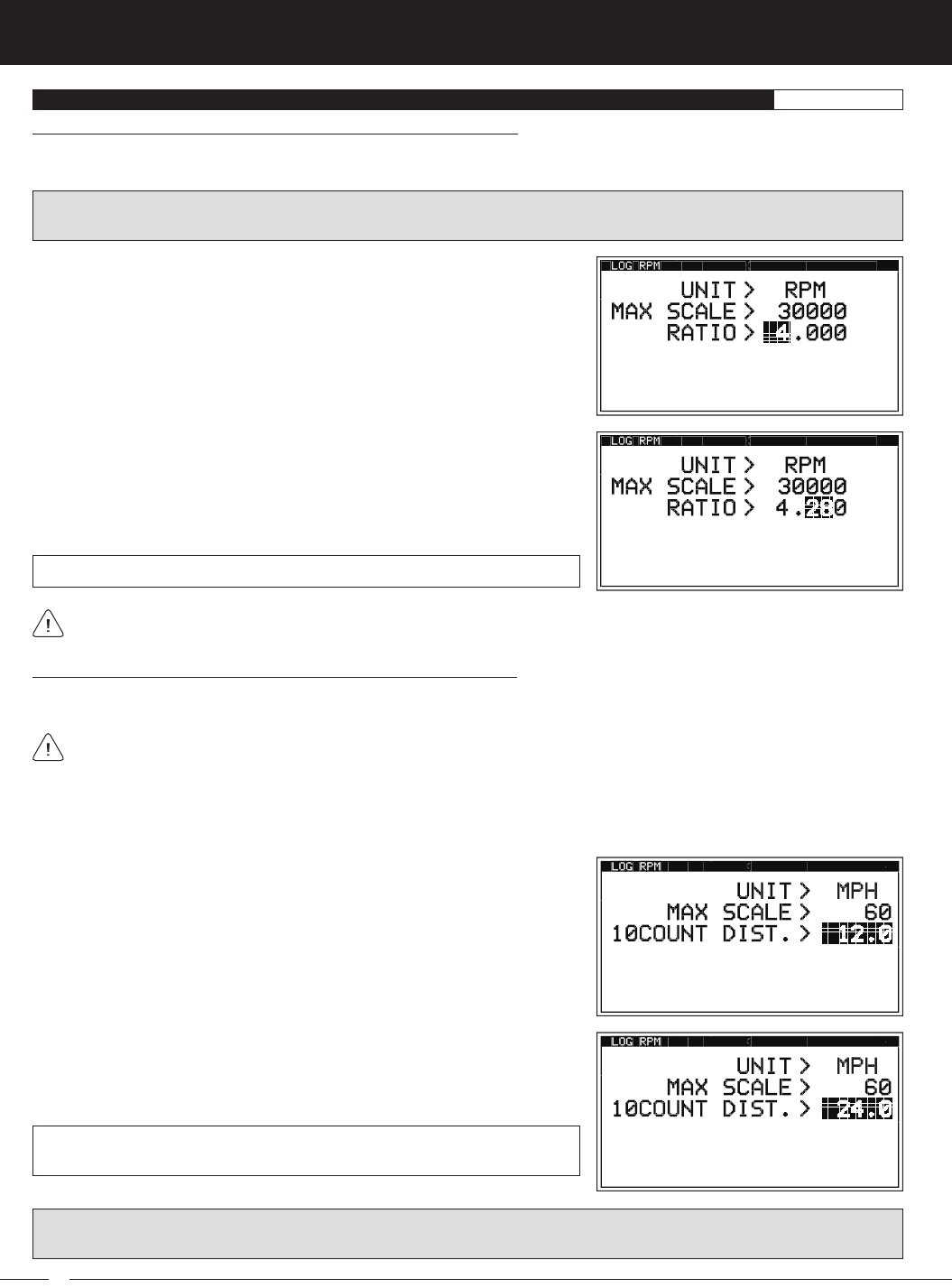
If the RPM sensor is mounted to your engine's flywheel or your motor's pinion gear to read the RPM directly, the Ratio value
should be set to 1.000.
LOG SETUP MENU {TELEMETRY DISPLAY AND LOGGING OPTIONS}SYSTEM
Calibrating the RPM Sensor - Changing the Ratio Value, Continued....
The Ratio value is the gear ratio between the two gears that the RPM sensor is mounted to. For example, if the RPM sensor is
mounted to your spur gear, the Ratio value will be the gear ratio of your spur gear and pinion gear.
RATIO setting range is 1.000 to 64.999. The default setting is 1.000.
3) Press the ENTER key, then scroll DOWN to highlight the second Ratio
value. Press the ENTER key, then scroll UP or DOWN to choose the desired
second Ratio value. If using the example above, choose 28.
4) If necessary, press the ENTER key, then scroll DOWN to highlight the third
ratio value. Press the ENTER key, then scroll UP or DOWN to choose the
desired third Ratio value.
IMPORTANT: To calculate the gear ratio, divide the number of teeth in the spur gear by the number of teeth in the pinion gear.
For example, if your spur gear is 60T and your pinion gear is 14T, the gear ratio is 60 / 14 = 4.28.
2) Press the ENTER key, then scroll UP or DOWN to choose the desired first Ratio
value. If using the example above, choose 4.
Calibrating the RPM Sensor - Changing the 10Count Distance Value:
The 10Count Distance value can be changed if you've Selected UNIT > MPH or UNIT > KM/H. By changing the 10Count Distance
value you are able to calibrate the RPM sensor to read your specific Model's actual speed, in either MPH or KM/H.
Prior to calibrating the RPM sensor, you must connect the RPM sensor to your receiver and correctly install the RPM sensor
into your Model. For more information, see the
Telemetry Connections and Mounting
section on pages 96 ~ 97.
3) From within the RPM menu and with UNIT > MPH or UNIT > KM/H Selected,
scroll UP or DOWN to highlight 10COUNT DIST > 12.0 or 10COUNT DIST > 30,
depending on the UNIT > value Selected previously.
1) With your transmitter and receiver turned ON, and with an Active Telemetry connection, place your Model on the ground.
2) Measuring in inches (or centimeters if using KM/H) from where you set your Model on the ground, slowly push your Model
and measure the distance covered to complete 10 full revolutions of the RPM sensor (the Bind LED on your receiver will flash
10 times, indicating 10 full revolutions).
4) Press the ENTER key, then scroll UP or DOWN to change the 10Count Distance
value to match the measurement obtained in step 2 above. For example, if
your Model traveled 2 feet (61cm) to complete 10 full revolutions, enter 24.0
(for MPH) or 61 (for KM/H).
10COUNT DIST setting range is 0.5 to 118.0 for MPH and 1 to 300 for KM/H. The
default setting is 12.0 for MPH and 30 for KH/H.
IMPORTANT: Changing the 10Count Distance value will change the Maximum Scale value. After calibration, you should reset
the Maximum Scale value back to the value you chose previously.
51
M12S 2.4GHZ FH4T RADIO CONTROL SYSTEM USER'S GUIDE
TR
LOG SETUP MENU {TELEMETRY DISPLAY AND LOGGING OPTIONS}SYSTEM
Receiver Battery Low Voltage Telemetry Data Display and Alert Alarm Options
The VOLT menu allows you to change the way receiver battery Voltage information is displayed on the TELEMETRY screen ALL
and VOLT pages and when the receiver battery Low Voltage Alert alarm sounds. For example, the Maximum Voltage value can
be adjusted to calibrate the VOLT Indicator on the TELEMETRY screen ALL page. In addition, you can adjust the Voltage value that
the receiver battery Low Voltage Alert alarm will sound at to match the type of receiver battery you're using.
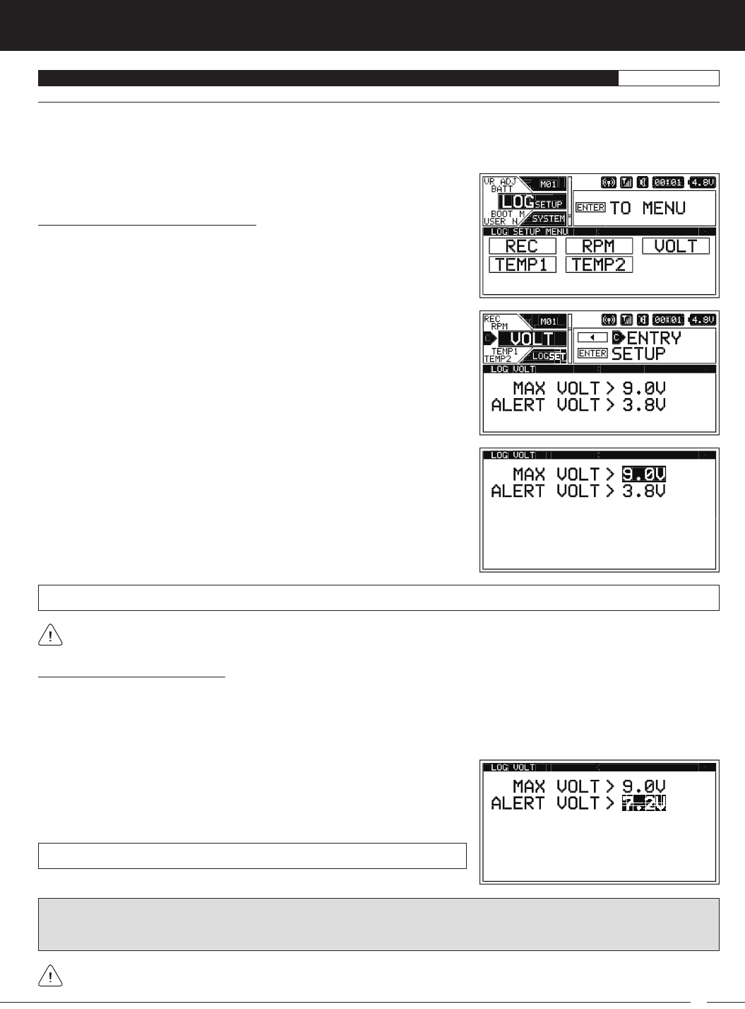
2) Press the ENTER key to open the LOG SETUP menu, then scroll UP or DOWN
to highlight the VOLT menu.
Changing the Maximum Voltage Value:
1) From within the SYSTEM menu, scroll UP or DOWN to highlight the LOG SETUP
menu.
3) Press the ENTER key to open the VOLT menu. MAX VOLT > 9.0V will be
highlighted.
4) Press the ENTER key, then scroll UP or DOWN to choose the desired Maximum
Voltage value. This value determines the Maximum Voltage that will be
displayed on the TELEMETRY screen VOLT page and also calibrates the VOLT
Indicator on the TELEMETRY screen ALL page. We suggest using a value that
matches as closely as possible the peaked voltage value of your receiver
battery after it's pulled off your charger.
MAX VOLT setting range is 3.0V to 9.0V. The default setting is 9.0V.
The Maximum Voltage value cannot be set Lower than the Alert Voltage value. If necessary, you may need to Lower the Alert
Voltage value prior to lowering the Maximum Voltage value.
Changing the Alert Voltage Value:
The Alert Voltage value determines the voltage at which the receiver battery Low Voltage Alert alarm will sound. For example, you
can set the Alert Voltage value to alert you to when your Model's receiver battery is getting low and needs to be recharged. When
the Alert Voltage value is reached, the Voltage Alert alarm will sound and LED2 will flash. The Low Voltage Alert alarm will sound
for approximately 5 seconds, however, LED2 will continue to flash until you recharge the receiver battery. The audible portion of
the Low Voltage Alert alarm can be cleared by pressing the BACK or ENTER keys.
1) From within the VOLT menu, scroll UP or DOWN to highlight ALERT VOLT > 3.8V.
2) Press the ENTER key, then scroll UP or DOWN to change the Alert Voltage
value. The Alert Voltage value is the voltage that the receiver battery Low
Voltage Alert alarm will sound at.
ALERT VOLT setting range is 3.0V to 9.0V. The default setting is 3.8V.
The Alert Voltage value cannot be set Higher than the Maximum Voltage value. If necessary, you may need to raise the
Maximum Voltage value prior to raising the Alert Voltage value.
IMPORTANT: Refer to the manufacturer of your Model's receiver battery to determine the safest Alert Voltage value to use. In
general, the Alert Voltage value should be high enough to alert you when it's time to recharge your receiver battery, but not so
low that the receiver can no longer control your Model or operate your servos optimally.
52
M12S 2.4GHZ FH4T RADIO CONTROL SYSTEM USER'S GUIDE
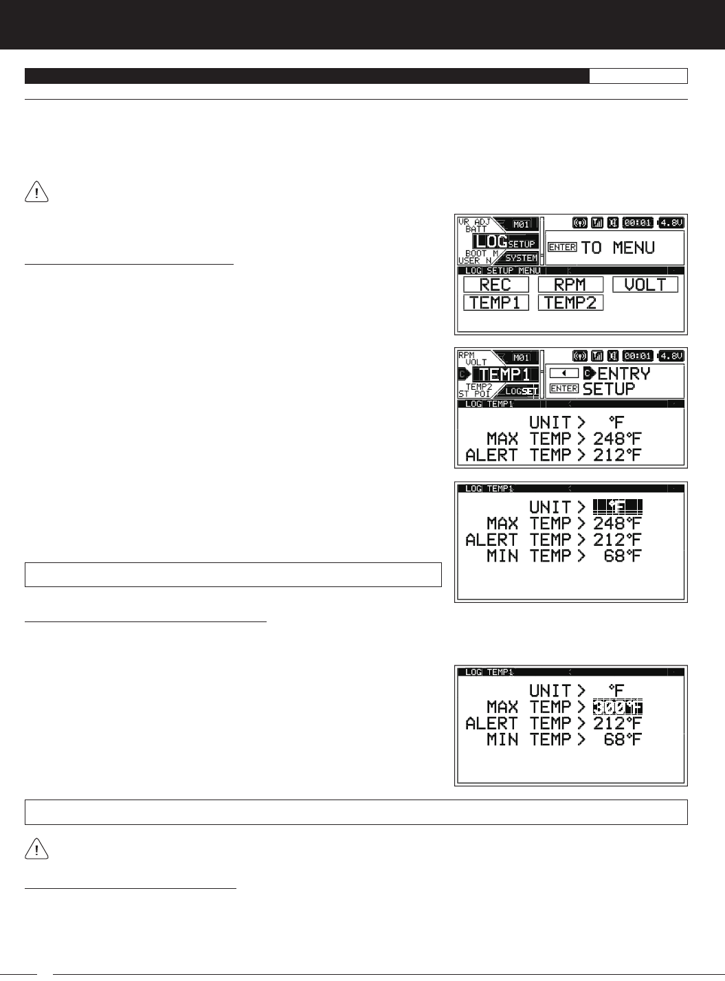
LOG SETUP MENU {TELEMETRY DISPLAY AND LOGGING OPTIONS}SYSTEM
2) Press the ENTER key to open the LOG SETUP menu, then scroll UP or DOWN
to highlight either the TEMP1 or the TEMP2 menu depending on which of the
two Temperature Sensor Ports you want to make changes to.
Changing the Temperature Unit Value:
1) From within the SYSTEM menu, scroll UP or DOWN to highlight the LOG SETUP
menu.
3) Press the ENTER key to open the TEMP1 or TEMP2 menu. UNIT > ºF will be
highlighted.
4) Press the ENTER key, then scroll UP or DOWN to choose the desired Temperature
Unit value, either Fahrenheit or Celsius.
UNIT setting range is ºF and ºC. The default setting is ºF.
Temperature 1 and Temperature 2 Telemetry Data Display and Alert Alarm Options
The TEMP1 and TEMP2 menus allow you to change the way Temperature information is displayed on the TELEMETRY screen
ALL and TEMP1 and/or TEMP2 pages, and when the Temperature Alert alarm sounds. For example, you can choose to display
Temperature values in either degrees Fahrenheit or degrees Celsius. In addition, the Maximum and Minimum Temperature values
can be adjusted to calibrate the TEMP1 and/or TEMP2 Indicator(s) on the TELEMETRY screen ALL page. You can also adjust the
Temperature value at which the Temperature Alert alarm will sound to suit the component the Temperature sensor is attached to.
This section covers both the TEMP1 and TEMP2 menus, since programming each of them is exactly the same. Choose either
the TEMP1 or the TEMP2 menu depending on which of the two Temperature Sensor Ports you want to make changes to.
Changing the Maximum Temperature Value:
The Maximum Temperature value determines the Maximum Temperature that will be displayed on the TELEMETRY screen
TEMP1 or TEMP2 page and also calibrates the TEMP1 or TEMP2 Indicator on the TELEMETRY screen ALL page.
The Maximum Temperature value cannot be set Lower than the Alert Temperature value or the Minimum Temperature value.
If necessary, you may need to Lower the Alert Temperature value prior to lowering the Maximum Temperature value.
1) From within the TEMP1 or TEMP2 menu, scroll UP or DOWN to highlight MAX
TEMP > 248ºF (or 120ºC).
2) Press the ENTER key, then scroll UP or DOWN to choose the desired Maximum
Temperature value.
MAX TEMP setting range is 68ºF to 302ºF (0ºC to 150ºC). The default setting is 248ºF (120ºC).
Changing the Alert Temperature Value:
The Alert Temperature value determines the temperature at which the Temperature Alert alarm will sound. For example, you can
set an Alert Temperature value for your nitro engine that will alert you when your engine's cylinder head temperature is getting too
hot. When the Alert Temperature value is reached, the Temperature Alert alarm will sound and LED2 will flash. The Temperature
Alert alarm will sound for approximately 5 seconds, however, LED2 will continue to flash until the temperature drops below the
Alert Temperature value. The audible portion of the Temperature Alert alarm can be cleared by pressing the BACK or ENTER keys.
53
M12S 2.4GHZ FH4T RADIO CONTROL SYSTEM USER'S GUIDE
TR
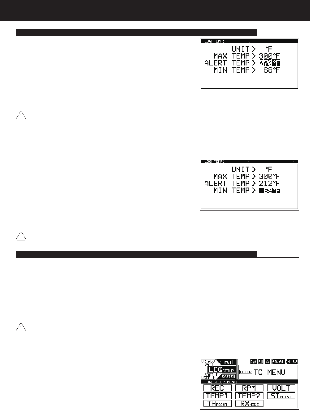
Changing the Alert Temperature Value, Continued....
1) From within the TEMP1 or TEMP2 menu, scroll UP or DOWN to highlight
ALERT TEMP 212ºF (or 100ºC).
2) Press the ENTER key, then scroll UP or DOWN to choose the desired Alert
Temperature value.
The Alert Temperature value cannot be set Higher than the Maximum Temperature value or Lower than the Minimum
Temperature value. If necessary, you may need to Lower the Minimum Temperature value prior to lowering the Alert
Temperature value.
ALERT TEMP setting range is 68ºF to 302ºF (0ºC to 150ºC). The default setting is 212ºF (100ºC).
LOG SETUP MENU {TELEMETRY DISPLAY AND LOGGING OPTIONS}SYSTEM
Changing the Minimum Temperature Value:
The Minimum Temperature value determines the Minimum Temperature that will be displayed on the TELEMETRY screen TEMP1
or TEMP2 page and also calibrates the TEMP1 or TEMP2 Indicator on the TELEMETRY screen ALL page.
1) From within the TEMP1 or TEMP2 menu, scroll UP or DOWN to highlight MIN
TEMP > 68ºF (or 20ºC).
2) Press the ENTER key, then scroll UP or DOWN to choose the desired Minimum
Temperature value.
MIN TEMP setting range is 32ºF to 302ºF (0ºC to 150ºC). The default setting is 68ºF (20ºC).
The Minimum Temperature value cannot be set Higher than the Alert Temperature value or the Maximum Temperature
value. If necessary, you may need to Increase these values prior to Increasing the Minimum Temperature value.
Receiver Mode
As described previously, when only the DISPLAY is turned ON using the DISPLAY key, the M12S can be placed in Receiver Mode,
allowing it to Bind with another Airtronics FH3 or FH4T transmitter and read Telemetry Data from it. For example, if using an FH4T
transmitter like the MT-4, MT-4 Telemetry Data can be viewed on the M12S TELEMETRY screen, or, if using an FH3 transmitter like
the MX-3X or M11X that doesn't support Telemetry, Steering and Throttle Output Data can still be viewed on the M12S TELEMETRY
screen. This capability allows the M12S to be used as a separate Telemetry Viewer and Recorder, much like the Airtronics TLS-
01 Telemetry Logger. To use this feature, first Bind your other transmitter to its receiver, then place the M12S in Receiver Mode
and Bind it to your other transmitter. With your other transmitter turned ON and operating your Model, you can use the M12S in
DISPLAY mode to view Telemetry data from the other transmitter.
This section details placing the M12S in Receiver Mode and making Steering and Throttle Point adjustments so that your paired
transmitter's Steering and Throttle Output Data is displayed correctly on the M12S's TELEMETRY screen.
The menus shown in this section are only available when using the M12S in DISPLAY mode. They are not available if the
M12S is turned ON using the Power Switch.
LOG SETUP MENU {DISPLAY ONLY TELEMETRY OPTIONS}SYSTEM
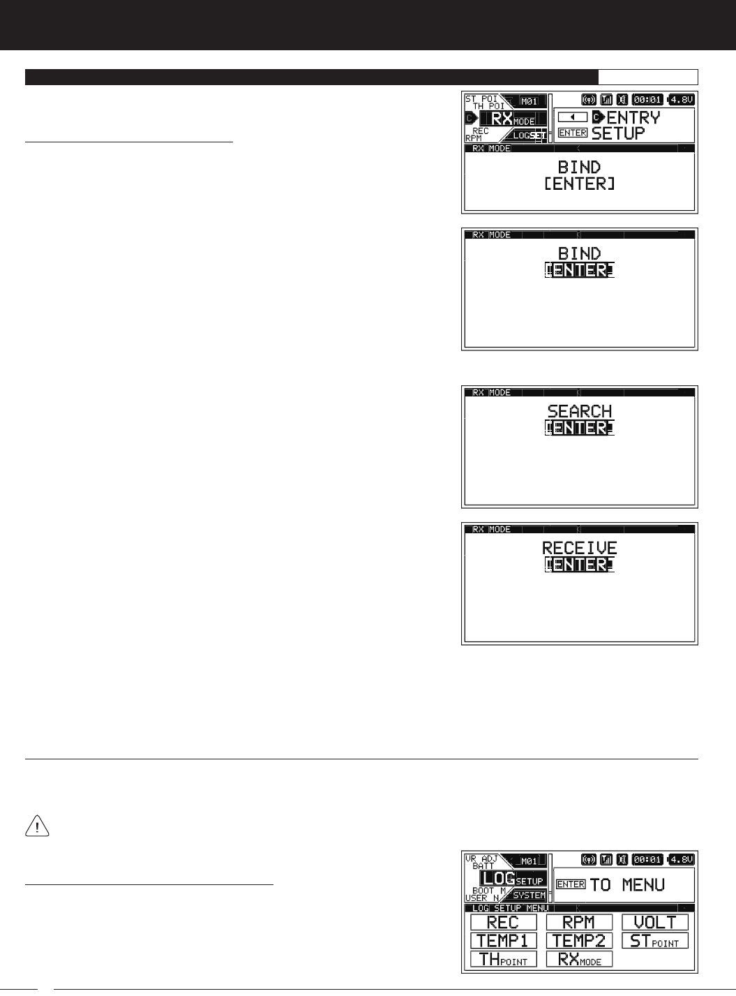
Using the RXMODE menu, you are able to place the M12S transmitter in Receiver Mode, which allows you to Bind the M12S trans-
mitter with another Airtronics FH3 or FH4T transmitter and read Telemetry Data from it.
Enabling Receiver Mode:
1) With the transmitter turned OFF, press and HOLD the DISPLAY key to turn only
the Display ON.
2) From within the SYSTEM menu, scroll UP or DOWN to highlight the LOG SETUP
menu.
54
M12S 2.4GHZ FH4T RADIO CONTROL SYSTEM USER'S GUIDE
LOG SETUP MENU {DISPLAY ONLY TELEMETRY OPTIONS}SYSTEM
5) Turn your other transmitter ON, then navigate to that transmitter's BIND menu and highlight the [ENTER] option. For more
information, refer to your transmitter's User's Guide.
4) Press the ENTER key to open the BIND menu. The Bind screen will be displayed
and [ENTER] will be highlighted.
7) Press the ENTER key on your other transmitter. RECEIVE will flash fast on the
M12S transmitter.
8) Press the BACK key, first on the M12S transmitter, then on your other transmitter, to complete the Binding process. The Bind LED
on your other transmitter should illuminate solid and both LED1 and LED2 on the M12S transmitter should be extinguished.
9) Press the BACK key to return to the STATUS screen, then scroll UP or DOWN to open the TELEMETRY screen. You should now be
able to view the other transmitter's Steering and Throttle Output Data on the M12S TELEMETRY screen. In addition, if your other
transmitter supports Telemetry,you should be able to view that transmitter's Telemetry Data on the M12S TELEMETRY screen.
6) Press the ENTER key on the M12S transmitter to begin the Binding process.
SEARCH will flash slowly.
Enabling Receiver Mode, Continued....
3) Press the ENTER key to open the LOG SETUP menu, then scroll UP or DOWN
to highlight the RXMODE menu.
Steering and Throttle Output Data Display Adjustments
The Steering Point and Throttle Point functions allow you to calibrate the M12S transmitter's TELEMETRY screen ALL page Steer-
ing and Throttle Output Data Displays, so the Output Data displayed matches your paired transmitter's Steering Wheel and
Throttle Trigger movement.
If you don't use the Steering Point and Throttle Point functions to calibrate the Steering and Throttle Output Data Displays,
incorrect data will be displayed. These steps should be performed after placing the M12S in Receiver Mode and Binding it
to your other transmitter.
Calibrating the Steering Output Data Display:
1) With the transmitter turned OFF, press and HOLD the DISPLAY key to turn only
the Display ON.
2) From within the SYSTEM menu, scroll UP or DOWN to highlight the LOG SETUP
menu.
55
M12S 2.4GHZ FH4T RADIO CONTROL SYSTEM USER'S GUIDE
TR
LOG SETUP MENU {DISPLAY ONLY TELEMETRY OPTIONS}SYSTEM
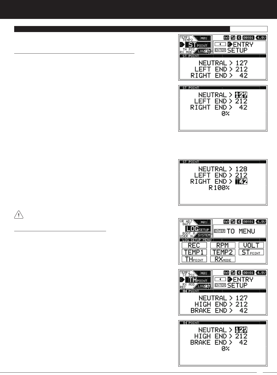
4) Press the ENTER key. The ST POINT menu will be displayed and NEUTRAL
POINT > 127 will be highlighted.
The values displayed in the ST POINT fields don't represent actual Steering Wheel movement and may vary. Steering Wheel
movement is displayed as a percentage below the ST POINT fields.
5) With your other transmitter turned ON and paired with the M12S transmitter, do the following:
A) Center the other transmitter's Steering Wheel, then press the ENTER key on the M12S transmitter.
B) Scroll DOWN to highlight LEFT END > 212. Rotate and HOLD the other transmitter's Steering Wheel all the way to the LEFT,
then press the ENTER key on the M12S transmitter.
C) Scroll DOWN to highlight RIGHT END > 42. Rotate and HOLD the other
transmitter's Steering Wheel all the way to the RIGHT, then press the
ENTER key on the M12S transmitter.
Calibrating the Steering Output Data Display, Continued....
3) Press the ENTER key to open the LOG SETUP menu, then scroll UP or DOWN
to highlight the STPOINT menu.
Calibrating the Throttle Output Data Display:
1) Without turning the transmitter ON, press and HOLD the DISPLAY key to turn
only the Display ON.
2) From within the SYSTEM menu, scroll UP or DOWN to highlight the LOG SETUP
menu.
3) Press the ENTER key to open the LOG SETUP menu, then scroll UP or DOWN
to highlight the THPOINT menu.
4) Press the ENTER key. The TH POINT menu will be displayed and NEUTRAL
POINT > 127 will be highlighted.
56
M12S 2.4GHZ FH4T RADIO CONTROL SYSTEM USER'S GUIDE
USER NAME MENU {TRANSMITTER USER NAMING}SYSTEM
The User Name function allows you to enter a User Name that is displayed on the STATUS screen, just above the M12S logo. This
allows you to actually Name or otherwise personalize your transmitter. The User Name can consist of up to 14 letters, numbers or
symbols. Choose from capital letters, Lower case letters, numbers and various symbols.
The values displayed in the TH POINT fields don't represent actual Throttle Trigger movement and may vary. Throttle Trigger
movement is displayed as a percentage below the TH POINT fields.
Calibrating the Throttle Output Data Display, Continued....
5) With your other transmitter turned ON and paired with the M12S transmitter, do the following:
A) Center the other transmitter's Throttle Trigger, then press the ENTER key on the M12S transmitter.
B) Scroll DOWN to highlight HIGH END > 212. Pull and HOLD the other transmitter's Throttle Trigger all the way BACK, then
press the ENTER key on the M12S transmitter.
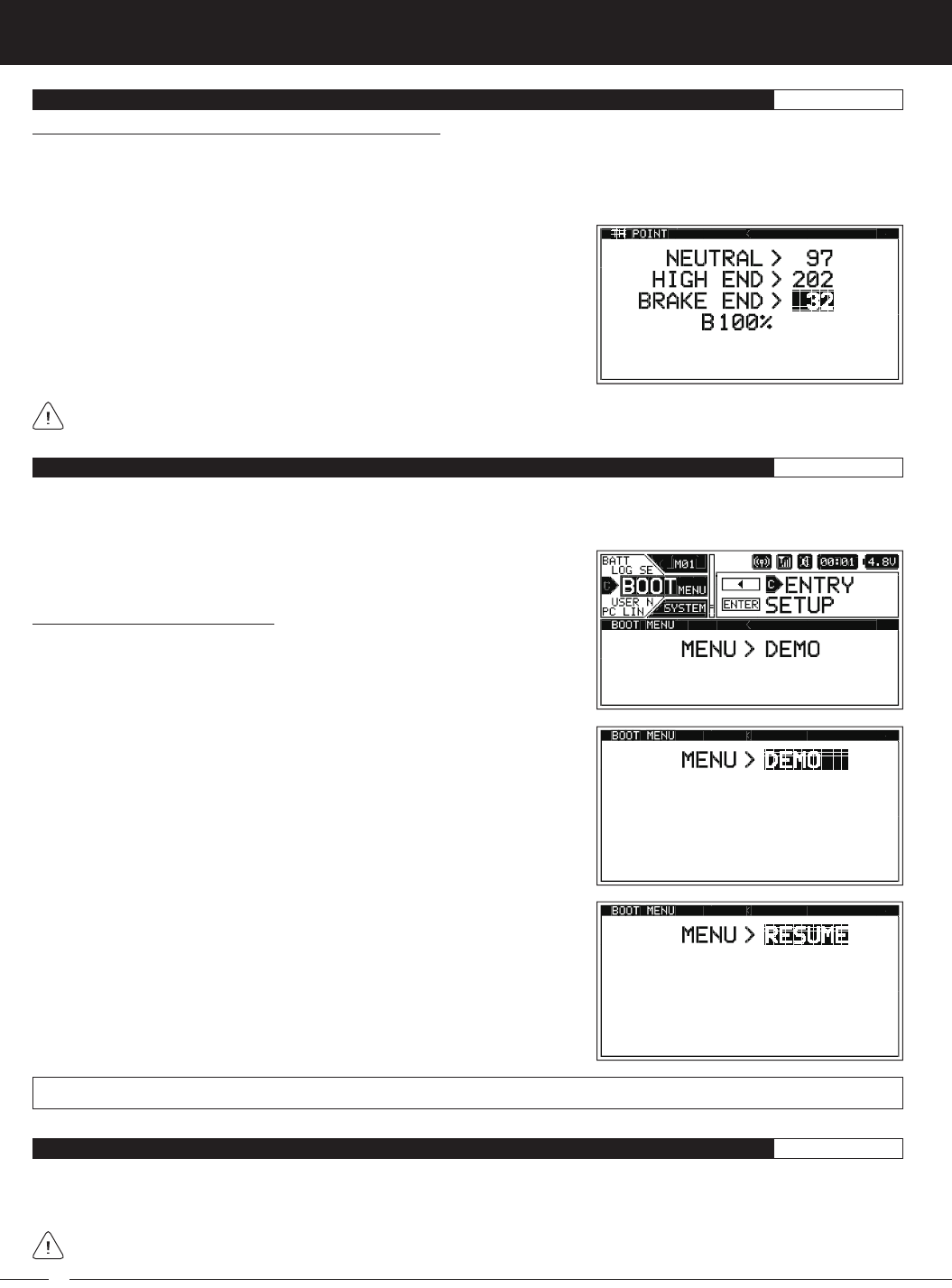
C) Scroll DOWN to highlight BRAKE END > 42. Push and HOLD the other
transmitter's Throttle Trigger all the way FORWARD, then press the ENTER
key on the M12S transmitter.
LOG SETUP MENU {DISPLAY ONLY TELEMETRY OPTIONS}SYSTEM
BOOT MENU {START-UP OPTIONS}SYSTEM
Changing the Boot Menu Options:
1) From within the SYSTEM menu, scroll UP or DOWN to highlight the BOOT
menu.
2) Press the ENTER key to open the BOOT menu. MENU > DEMO will be
highlighted.
The Boot menu allows you to change the default start-up behavior of the transmitter when it's turned ON. For example, when you
turn the transmitter ON you can have it temporarily display the Logo (DEMO) before defaulting to the STATUS screen, you can
have it Resume from the last Programming Menu you were in when the transmitter was turned OFF (RESUME) or you could have
the transmitter default to the STATUS screen (TOP).
3) Press the ENTER key, then scroll UP or DOWN to choose the desired Boot
Menu value. When DEMO is Selected, the Logo will be displayed during the
start-up process, then default to the STATUS screen. When RESUME is
Selected, the transmitter will display the last Programming Menu you were in
when the transmitter was turned OFF. When TOP is Selected, the transmitter
will default to the STATUS screen when turned ON.
MENU setting range is DEMO, RESUME and TOP. The default setting is DEMO.
If the User Name is Left blank, the Airtronics logo will be displayed in its place.
57
M12S 2.4GHZ FH4T RADIO CONTROL SYSTEM USER'S GUIDE
TR
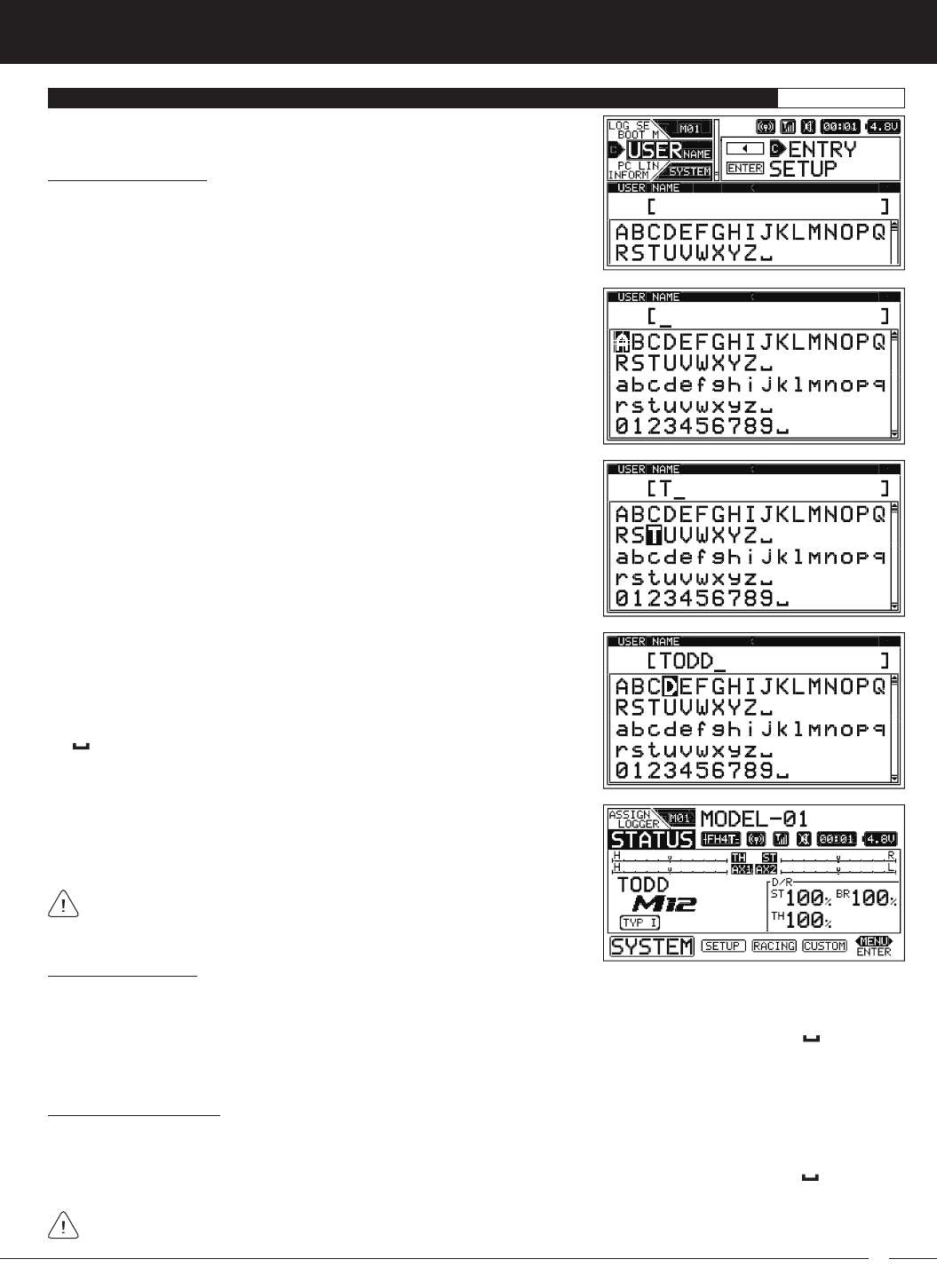
Entering a User Name:
1) From within the SYSTEM menu, scroll UP or DOWN to highlight the USER
NAME menu.
2) Press the ENTER key to open the USER NAME menu. The underscore will be
positioned under the first space in the User Name. Press the ENTER key a
second time
3) Scroll UP or DOWN and press the SELECT switch RIGHT or LEFT to highlight a
character in the Character List. Press the ENTER key to Select the highlighted
character. That character will be displayed in the User Name and the underscore
will advance to the next space.
USER NAME MENU {TRANSMITTER USER NAMING}SYSTEM
4) Repeat step 3 to enter the rest of the characters. Up to 14 characters can be
entered. If desired, press the BACK key to re-gain control of the underscore,
then use the SELECT switch or scroll UP or DOWN to move the underscore
RIGHT or LEFT. To add a space (or spaces) in your Model Name, use the
character.
5) When you return to the STATUS screen, your User Name will be displayed
above the M12S Logo on the Left side of the screen.
If the User Name is Left blank, the Airtronics logo will be displayed in its
place.
Deleting a Character:
1) Press the SELECT switch RIGHT or LEFT or scroll UP or DOWN to move the underscore under the character in your User Name
you want to delete.
2) Press the ENTER key, then scroll UP or DOWN and press the SELECT switch RIGHT or LEFT to highlight the character in
the Character List. Press the ENTER key. The character in your User Name will be deleted and the underscore will advance to
the next space.
Deleting the User Name:
1) Press the SELECT switch RIGHT or LEFT or scroll UP or DOWN to move the underscore under the first character in your User
Name.
2) Press the ENTER key, then scroll UP or DOWN and press the SELECT switch RIGHT or LEFT to highlight the character in
the Character List. Continuously press the ENTER key to delete each character in your User Name.
If you can't move the underscore, press the BACK key to re-gain control of the underscore.
58
M12S 2.4GHZ FH4T RADIO CONTROL SYSTEM USER'S GUIDE
PC LINK MENU {SAVE TRANSMITTER DATA AND UPDATE FIRMWARE}SYSTEM
The PCLINK menu allows you to Save the current Telemetry Data Log to your PC for viewing at a later date. Once a Telelmetry Data
Log is Saved to your PC, the data can be read using a spreadsheet program, such as Microsoft Excel. In addition, the PCLINK menu
allows you to Save Model Programming Data to your PC, Load saved Model Programming Data from your PC, and use your PC
to update the M12S transmitter's Firmware.
To use these functions, a Mini USB cable and PC-Link Manager software will be required. Visit http://www.airtronics.net to
download the PC-Link Manager software and check for Firmware updates. A Mini USB cable should be available from any
retail store that sells PC accessories.
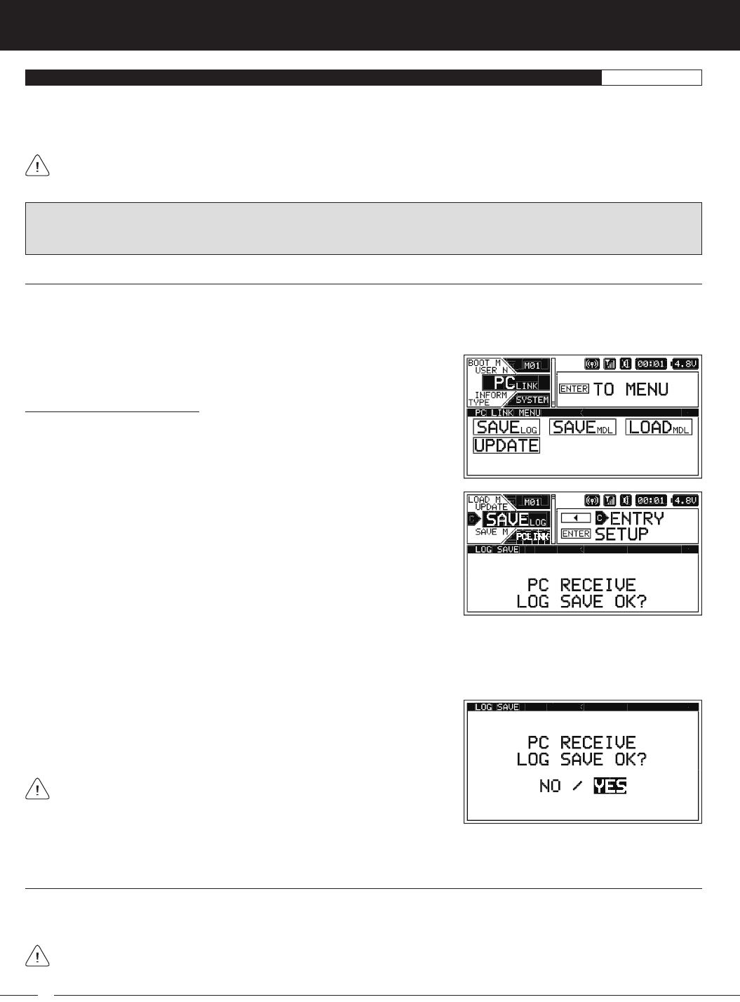
Saving the Telemetry Data Log:
1) From within the SYSTEM menu, scroll UP or DOWN to highlight the PCLINK
menu.
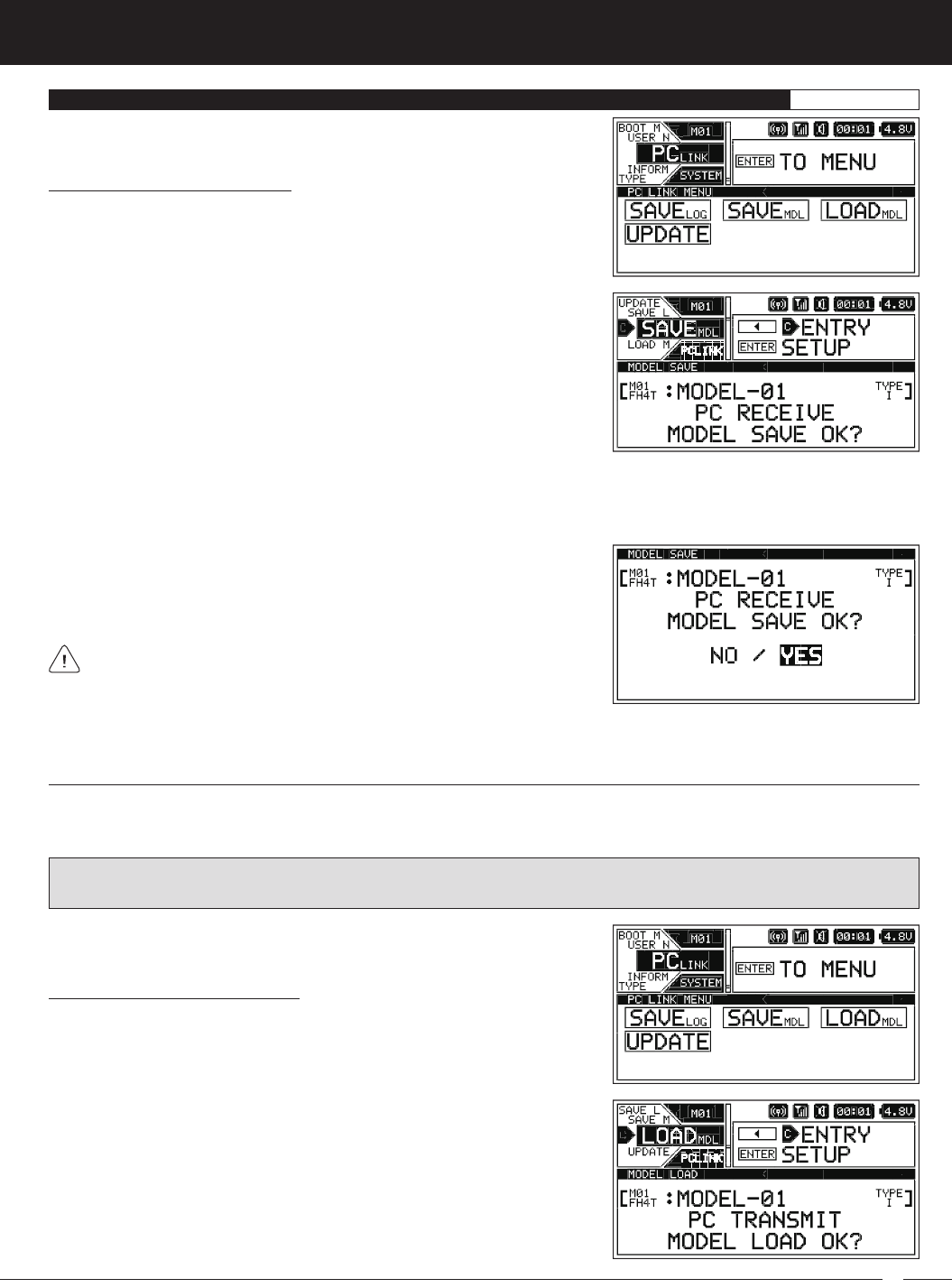
2) Press the ENTER key to open the PCLINK menu, then scroll UP or DOWN to
highlight the SAVELOG menu.
Saving the Telemetry Data Log
The Save Log function allows you to Save the current Telemetry Data Log for viewing or archiving on your PC. The Telemetry Data
Recording function records Telemetry Data when the Lap Timer is Started. When the Lap Timer is Stopped, Telemetry Recording
is also Stopped. One Telemetry Data Log is kept in memory at a time and will be available for viewing even after the transmitter
is turned OFF. When the Lap Timer is Started again, the current Telemetry Data Log will be erased and a new one Started. If you
want to Save the current Telemetry Data Log, follow the steps in this section.
7) Click the Start button on the PC-Link Manager software and allow the Data Transfer to complete. Once completed, EXECUTED
will be displayed on the M12S and The Operation Was Completed will be displayed on your PC.
IMPORTANT: Before proceeding, make sure that the transmitter is turned ON and connected to your PC, and that the PC-Link
Manager software is installed on your PC and running. For more information, refer to the User's Guide included with the PC-Link
Manager software.
3) Click the LOG SAVE TX > PC button on the PC-Link Manager software.
4) Navigate to the folder you would like to save the Telemetry Data Log to, then type a name for the file and click the Save button.
Do not click the Start button on the PC-Link Manager software yet.
5) Press the ENTER key. PC RECEIVE LOG SAVE OK? NO/YES will be displayed.
6) Scroll UP or DOWN to highlight YES, then press the ENTER key. PC START will
be displayed.
If you want to go back or if you don't want to Save the Telemetry Data Log
for any reason, choose NO or press the BACK key.
Saving Model Programming Data
The Model Save function allows you to Save the currently Selected Model's Programming Data to your PC, either for archiving or for
sharing with other M12S users. For example, you can Save your current Model's Programming Data to your PC, then share the file
with a friend or fellow driver. They can then upload that Programming Data to their M12S transmitter using the Model Load function.
Only the currently Selected Model's Programming Data will be Saved. To Save the Programming Data for a different
Model, you must Select that Model first, using Model Select function. For more information, see the
Model Select
section
on pages 25 ~ 26.
59
M12S 2.4GHZ FH4T RADIO CONTROL SYSTEM USER'S GUIDE
TR
Saving Model Programming Data:
1) From within the SYSTEM menu, scroll UP or DOWN to highlight the PCLINK
menu.
PC LINK MENU {SAVE TRANSMITTER DATA AND UPDATE FIRMWARE}SYSTEM
2) Press the ENTER key to open the PCLINK menu, then scroll UP or DOWN to
highlight the SAVEMDL menu.
3) Click the MODEL SAVE TX > PC button on the PC-Link Manager software.
4) Navigate to the folder you would like to save the Model Programming Data to, then type a name for the file and click the Save
button. Do not click the Start button on the PC-Link Manager software yet.
7) Click the Start button on the PC-Link Manager software and allow the Data Transfer to complete. Once completed, EXECUTED
will be displayed on the M12S and The Operation Was Completed will be displayed on your PC.
5) Press the ENTER key. PC RECEIVE MODEL SAVE OK? NO/YES will be displayed.
6) Scroll UP or DOWN to highlight YES, then press the ENTER key. PC START will
be displayed.
If you want to go back or if you don't want to Save the Model Programming
Data for any reason, choose NO or press the BACK key.
Loading Model Programming Data
The Model Load function allows you to Load Model Programming Data from your PC onto your transmitter. For example, if you've
archived a Model's Programming Data onto your PC, you can restore it onto the transmitter or you can Load a Model's Programming
Data that a friend or fellow driver has provided to you.
WARNING: When you Load Model Programming Data from your PC, that Model Programming Data will overwrite the
Programming Data of the currently Selected Model. Please make sure you first load a Model that you don't want to overwrite!
Loading Model Programming Data:
1) From within the SYSTEM menu, scroll UP or DOWN to highlight the PCLINK
menu.
2) Press the ENTER key to open the PCLINK menu, then scroll UP or DOWN to
highlight the LOADMDL menu.
60
M12S 2.4GHZ FH4T RADIO CONTROL SYSTEM USER'S GUIDE
PC LINK MENU {SAVE TRANSMITTER DATA AND UPDATE FIRMWARE}SYSTEM
Loading Model Programming Data, Continued....
3) Click the MODEL LOAD PC > TX button on the PC-Link Manager software.
4) Navigate to the folder where your Saved Model File is, then Select the file and click the Open button. Do not click the Start button
on the PC-Link Manager software yet.
7) Click the Start button on the PC-Link Manager software and allow the Data Transfer to complete. Once completed, EXECUTED
will be displayed on the M12S and The Operation Was Completed will be displayed on your PC.
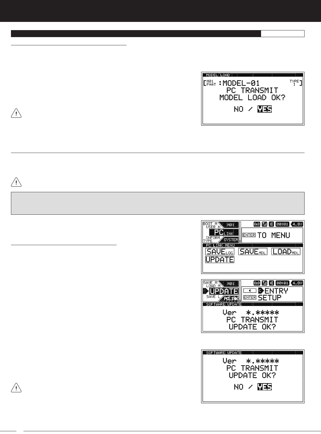
5) Press the ENTER key. PC TRANSMIT MODEL LOAD OK? NO/YES will be
displayed.
6) Scroll UP or DOWN to highlight YES, then press the ENTER key. PC START will
be displayed.
If you want to go back or if you don't want to Load the Model Programming
Data for any reason, choose NO or press the BACK key.
Updating Transmitter Firmware Version
The Update function allows you to Update the transmitter's Firmware to the latest version available. This allows you to keep your
transmitter up to date with any future programming feature upgrades or additions. The Firmware version that your transmitter is
currently running is shown in the INFORMATION menu. For more information, see the
INFORMATION Menu
section on page 61.
Before proceeding, download and save the latest Firmware version to a convenient location on your PC. Updates (when
available) can be downloaded from our website at http://www.airtronics.net.
Updating the Transmitter Firmware Version:
1) From within the SYSTEM menu, scroll UP or DOWN to highlight the PCLINK
menu.
2) Press the ENTER key to open the PCLINK menu, then scroll UP or DOWN to
highlight the UPDATE menu.
WARNING: The Update process will take approximately 5 to 10 minutes. Make sure that before starting the Update process
that the transmitter's battery voltage is sufficient to complete the Update process. Once started, DO NOT STOP the Update
process and DO NOT unplug the transmitter from your PC!
3) Click the SOFTWARE UPDATE button on the PC-Link Manager software.
4) Navigate to the folder where you Saved the new Firmware version, then Select the file and click the Open button. Do not click the
Start button on the PC-Link Manager software yet.
7) Click the Start button on the PC-Link Manager software and allow the Update process to complete. Once completed, The
Operation Was Completed will be displayed on your PC and transmitter will Reset. Turn the transmitter OFF, unplug the Mini
USB cable from the transmitter, then turn the transmitter back ON to finalize the Update process.
5) Press the ENTER key. PC TRANSMIT UPDATE OK? NO/YES will be displayed.
6) Scroll UP or DOWN to highlight YES, then press the ENTER key. PC START will
be displayed.
If you want to go back or if you don't want to Update the Firmware version
for any reason, choose NO or press the BACK key.
61
M12S 2.4GHZ FH4T RADIO CONTROL SYSTEM USER'S GUIDE
TR
INFORMATION MENU {FIRMWARE VERSION AND ON-TIME}SYSTEM
Resetting the On-Time:
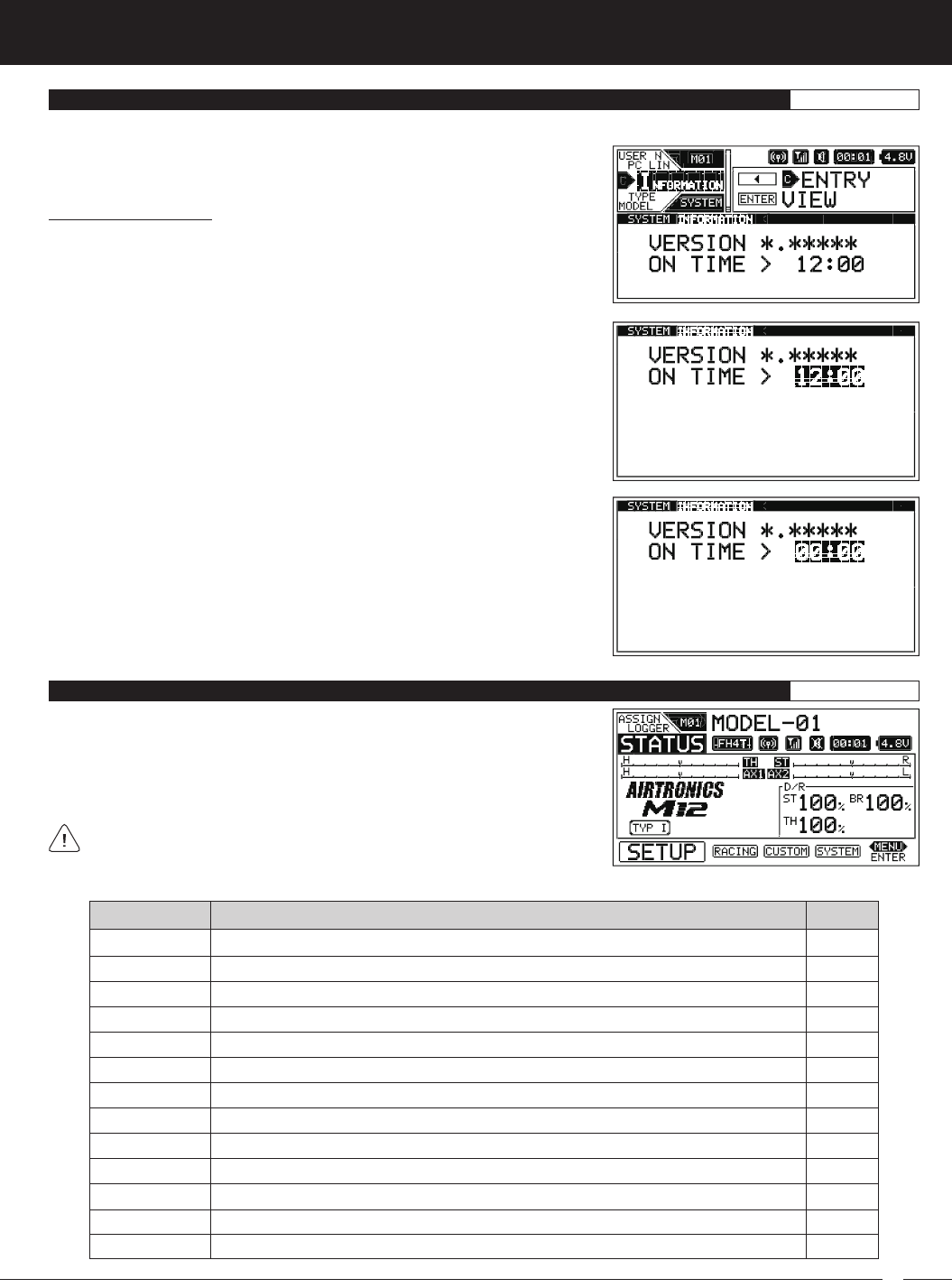
1) From within the SYSTEM menu, scroll UP or DOWN to highlight the INFORMATION
menu.
2) Press the ENTER key to open the INFORMATION menu. ON TIME > 00:00 (or
the actual Cumulative On-Time) will be highlighted and the current Firmware
version will be displayed.
The INFORMATION menu allows you to view the transmitter's current Firmware version, in addition to the transmitter's cumulative
On-Time in Hours and Minutes.
3) Press and HOLD the ENTER key to Reset the ON TIME to 00:00. Cumulative
On-Time will continue to accrue whether the transmitter is turned ON or if
only the Display is turned ON using the DISPLAY key. If Reset to 00:00 after
changing or recharging the transmitter batteries, it can be used to determine
battery discharge time.
EPA
SUB TRIM
REV
POINT AX1
POINT AX2
MOA MIX
4WS MIX
FEELING
F/S
B-F/S
LAP TIMER
INT1
INT2
PG. 62
PG. 63
PG. 64
PG. 64
PG. 65
PG. 66
PG. 67
PG. 69
PG. 69
PG. 70
PG. 71
PG. 73
PG. 73
MENU PAGE #
MENU DESCRIPTION
Adjust Channel End Points to Balance Servo Travel
Adjust Servo Centering to Center the Servo Horns
Change the Direction of Servo Travel
Adjust Auxiliary 1 Point Values to Change the Servo Stepping Behavior
Adjust Auxiliary 2 Point Values to Change the Servo Stepping Behavior
Adjust and Change Dual Motor Mixing options (Crawler Car Types Only)
Adjust and Change Four Wheel Steering Mixing Options (Crawler Car Types Only)
Adjust Steering and Throttle Channel Latency Values
Program Fail Safe Settings
Program Receiver Battery Fail Safe Settings to Ensure Optimum Servo Performance
Program the Lap Timer Goal Time, Pre-Alarm and Lap Timer Start Options
Program Interval Timer 1 and Change its Start Options
Program Interval Timer 2 and Change its Start Options
The following Programming Menus are available within the SETUP menu:
To access the various SETUP Programming Menus, turn the transmitter ON, then
press the SELECT switch to highlight the SETUP menu. Press the ENTER key to
open the SETUP menu.
Scroll UP or DOWN to highlight the desired Programming Menu, then press the
ENTER key to open that menu.
Depending on the Car Type chosen, some Function Programming Value
Names may differ from those shown in this section.
SETUP MENU OVERVIEW SETUP
62
M12S 2.4GHZ FH4T RADIO CONTROL SYSTEM USER'S GUIDE
EPA MENU {CHANNEL END POINT ADJUSTMENTS}SETUP
The End Point Adjustment function allows you to adjust servo travel in each direction. This makes it possible to balance servo
travel in both directions and set the maximum desired amount of servo travel. For example, on a gas-powered Model, if you pull
the Throttle Trigger and the carburetor does not open completely, you can Increase the Throttle High End Point Adjustment so
that the carburetor opens completely. Another example is with Steering. If your Model turns sharper to the Right than to the Left,
you can Increase the Steering Left End Point Adjustment to balance the Steering.
The End Point Adjustment function can be adjusted for the Steering channel (Right and Left), the Throttle channel (High and
Brake), the Auxiliary 1 channel (High and Low) and the Auxiliary 2 channel (High and Low).
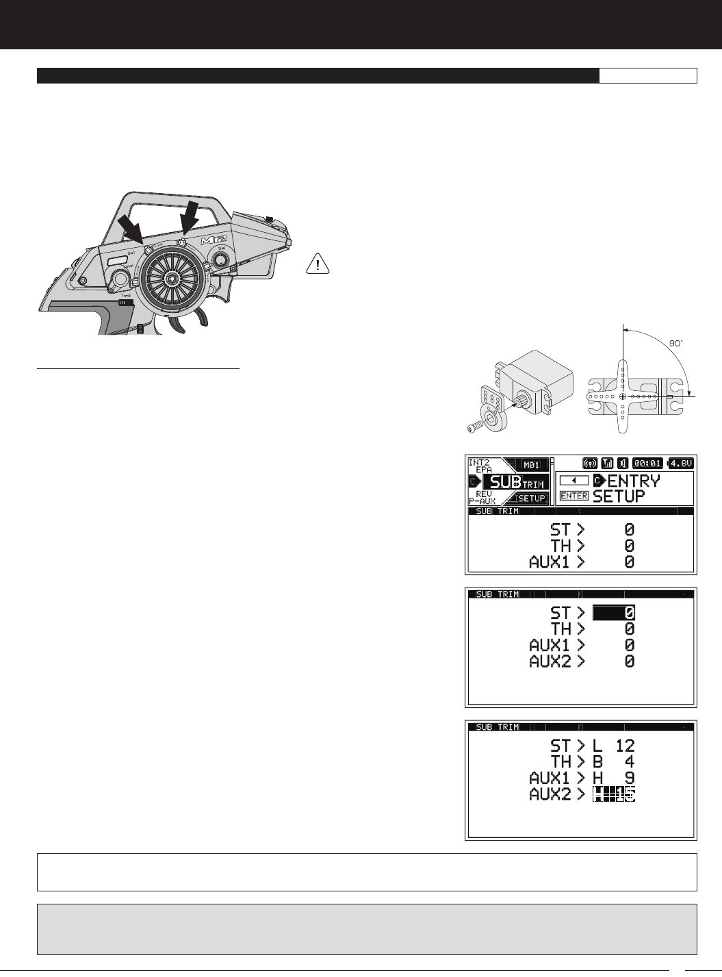
Before making End Point Adjustments, the servo horn needs to be centered. Install the servo horn onto the servo, making
sure it's as close to being centered as possible, then use the Servo Sub-Trim function to center the servo arm exactly. For
more information, see the
SUB TRIM Menu
section on page 63.
Changing the Channel End Point Adjustment Percentage Values:
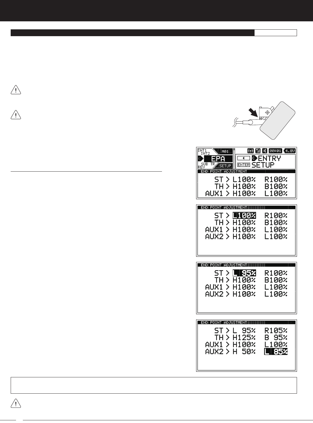
1) From within the SETUP menu, scroll UP or DOWN to highlight the EPA menu.
2) Press the ENTER key to open the EPA menu. The cursor will default to either
ST > L100% or ST > R100%.
3) Scroll UP or DOWN to highlight the desired End Point Adjustment percentage
value you would like to change.
4) Press the ENTER key, then scroll UP or DOWN to Increase or Decrease the
End Point Adjustment percentage value. Increasing the percentage value will
Increase servo travel in that direction and Decreasing the percentage value
will Decrease servo travel in the that direction.
If you're using an Electronic Speed Control, the Throttle High and the Throttle Brake End Point Adjustment percentage
values are both generally set to 100%, although the Throttle High direction may need to be increased to achieve full power.
In some cases, Throttle and Brake End Point Adjustments can also be set directly via the Electronic Speed Control.
5) Press the ENTER key, then repeat steps 3 and 4 to change any other desired
End Point Adjustment percentage values.
ST L and R setting range is 0% to 150%, TH H and B setting range is 0% to 150%, AUX1 H and L setting range is 0% to 150%
and AUX2 H and L setting range is 0% to 150%. The default setting for all channels is 100%.
End Point Adjustment percentage values should not be increased to the point where your
linkages and servos Bind when moved all the way to the Right or Left. Binding will cause
the servos to 'buzz', resulting in a quicker loss of receiver battery power and eventual damage to
the servos or to your Model.
63
M12S 2.4GHZ FH4T RADIO CONTROL SYSTEM USER'S GUIDE
TR
SUB TRIM MENU {SERVO CENTERING}SETUP
The Sub-Trim function allows you to correct the Neutral Trim setting for the Steering, Throttle, Auxiliary 1 and Auxiliary 2 channels,
making it possible to center the Trim Switches while ensuring the servo horns remain centered.
It's not unusual that when you center a servo and install the servo horn, the servo horn is not exactly centered. The Sub-Trim
function allows you to center the servo horn exactly, without altering the servo End Point travel. This is especially useful
when using a Mix, such as Four Wheel Steering Mixing. For example, you can use the Sub-Trim function to adjust the Neutral
Trim setting of your Front and Rear Steering servos independently to ensure your Model tracks straight.
Before changing the Sub-Trim values you should set the Steering and
Throttle Trim to 0% using the Trm1 and Trm2 Trim Switches.
Changing the Servo Sub-Trim Values:
1) Install the servo horn (or servo saver for the Steering servo) onto your servo,
making sure that the servo horn (or servo saver) is as close to being centered
as possible. In some cases, you can get the servo horn closer to being
centered by rotating the servo horn 180º and reinstalling it.
2) From within the SETUP menu, scroll UP or DOWN to highlight the SUB TRIM
menu.
3) Press the ENTER key to open the SUB TRIM menu. The cursor will default to
ST > 0.
4) Scroll UP or DOWN to highlight the desired Sub-Trim value you would like to
change.
5) Press the ENTER key, then scroll UP or DOWN to Increase or Decrease the
Sub-Trim value only enough to center the servo horn.
6) Press the ENTER key, then repeat steps 4 and 5 to change any other desired
Sub-Trim values.
ST setting range is R150 to L150, TH setting range is H150 to B150, AUX1 setting range is H150 to L150 and AUX2 setting range
is H150 to L150. The default setting for all channels is 0.
IMPORTANT: Changing the Sub-Trim values will alter the servo's End Points. After changing the Sub-Trim values, use the End
Point Adjustment function to Reset the servo End Point Adjustment Percentage Values. For more information, see the
Changing
the Channel End Point Adjustment Percentage Values
section on the previous page.
64
M12S 2.4GHZ FH4T RADIO CONTROL SYSTEM USER'S GUIDE
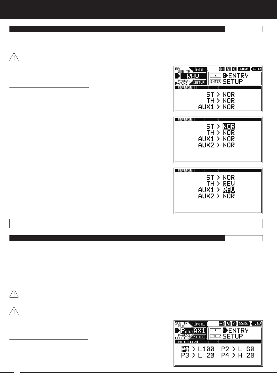
REV MENU {SERVO REVERSING}SETUP
The Servo Reversing function allows you to electronically switch the direction of servo travel. For example, if you rotate the Steering
Wheel to the Right, and the Steering servo moves to the Left, you can use the Servo Reversing function to make the Steering servo
move to the Left. The Servo Reversing function is available for all four channels.
When you change the direction of servo travel, the servo horn may no longer be centered. If this occurs, use the Servo
Sub-Trim function to center the servo horn. For more information, see the Changing the
Servo Sub-Trim Values
section on
the previous page.
Changing the Servo Reversing Values:
1) From within the SETUP menu, scroll UP or DOWN to highlight the REV menu.
2) Press the ENTER key to open the REV menu. The cursor will default to ST > NOR.
3) Scroll UP or DOWN to highlight the desired Servo Reversing value you would
like to change.
4) Press the ENTER key, then scroll UP or DOWN to change the Servo Reversing
value. Choose from either NOR (Normal) or REV (Reverse).
5) Press the ENTER key, then repeat steps 3 and 4 to change any other desired
Servo Reversing values.
ST, TH, AUX1 and AUX2 setting range is NOR and REV. The default setting for all channels is NOR.
POINT AUX1 MENU {AUXILIARY 1 POINT VALUES}SETUP
The Point Auxiliary function allows you to program the Auxiliary 1 servo to move up to 6 different Points along its travel, then cycle
through those Points using one of the Trim Switches or the Rotary Dial. For example, if your Model requires a separate 3-position
or more switch to operate a feature, the Point Auxiliary function can be customized to control this. This section details how to
change the actual Point values. For example, if you have 4 Points programmed, you can change the Point values to cycle your
servo from 0 to 20 to 40 to 60 degrees and back again.
Use one of the five Trim Switches or the Auxiliary Dial to cycle through the Point Positions while you're driving. The Auxiliary Lever
is not suitable for use in this situation. The Point Auxiliary function can be toggled OFF and ON while you're driving by Assigning
AUX1 to one of the three Push-Button Switches.
Prior to programming the Auxiliary 1 Point values, you must first change the Auxiliary Channel Operating Mode to
POINT, then choose the number of Points you want to program. For more information, see the
AUX TYPE Menu
section
on pages 41 ~ 42.
The Step value for the Auxiliary Dial or Trim Switch should be set to 1, otherwise the transmitter won't cycle properly through
the programmed Points. For more information, see the
Changing the Trim Switch Step Value
section on page 35 or the
Changing the Auxiliary Dial Step Value
section on pages 36 ~ 37.
Changing the Auxiliary 1 Point Values:
1) From within the SETUP menu, scroll UP or DOWN to highlight the POINT AX1
menu.
65
M12S 2.4GHZ FH4T RADIO CONTROL SYSTEM USER'S GUIDE
TR
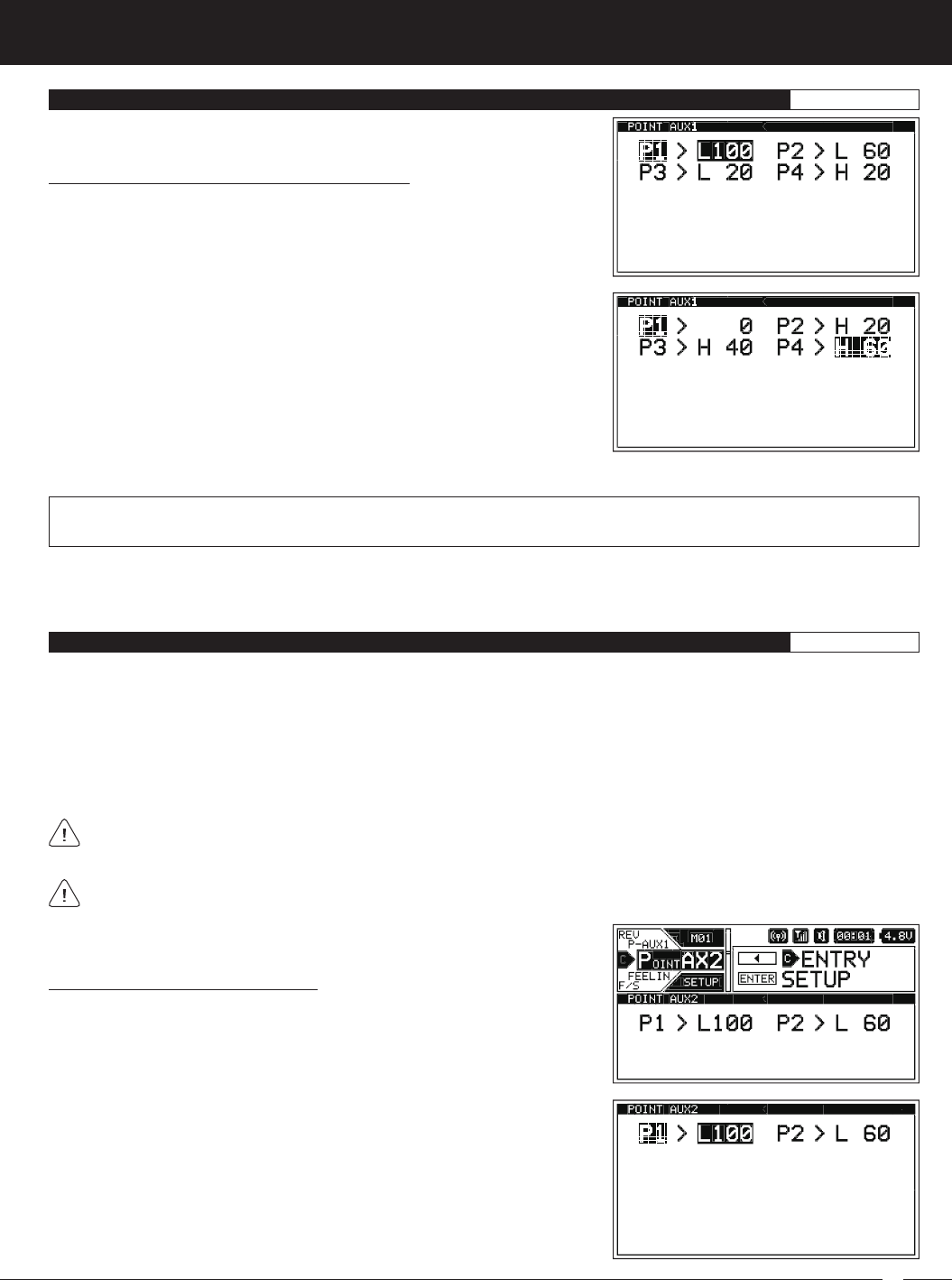
POINT AUX1 MENU {AUXILIARY 1 POINT VALUES}SETUP
Changing the Auxiliary 1 Point Values, Continued....
2) Press the ENTER key to open the POINT AX1 menu. The cursor will default to
P1 > L100 and the current Point will be highlighted.
P1 though P6 setting range is H100 to L100. The default setting for P1 is L100, for P2 is L60, for P3 is L20, for P4 is H20, for P5 is
H60 and for P6 is H100. These values are a percentage of Auxiliary 1 servo travel.
3) Scroll UP or DOWN to highlight the desired Point value you would like to
change.
4) Press the ENTER key, then scroll UP or DOWN to change the Point value.
Choosing an H or L value will determine the direction the servo travels.
6) Cycle forward and backward through the Points using the Auxiliary Dial (default) or the Trim Switch you Assigned AUX1 to. You
will notice that as you cycle through the Points, the current Point will be highlighted and in addition, the current Point will be
displayed in a pop-up window.
POINT AUX2 MENU {AUXILIARY 2 POINT VALUES}SETUP
The Point Auxiliary function allows you to program the Auxiliary 2 servo to move up to 6 different Points along its travel, then cycle
through those Points using one of the Trim Switches or the Rotary Dial. For example, if your Model requires a separate 3-position
or more switch to operate a feature, the Point Auxiliary function can be customized to control this. This section details how to
change the actual Point values. For example, if you have 4 Points programmed, you can change the Point values to cycle your
servo from 0 to 20 to 40 to 60 degrees and back again.
Use one of the five Trim Switches or the Auxiliary Dial to cycle through the Point Positions while you're driving. The Auxiliary Lever
is not suitable for use in this situation. The Point Auxiliary function can be toggled OFF and ON while you're driving by Assigning
AUX2 to one of the three Push-Button Switches.
Prior to programming the Point Auxiliary 2 Point values, you must first change the Auxiliary Channel Operating Mode to
POINT, then choose the number of Points you want to program. For more information, see the
AUX TYPE Menu
section on
pages 41 ~ 42.
The Step value for the Auxiliary Dial or Trim Switch should be set to 1, otherwise the transmitter won't cycle properly through
the programmed Points. For more information, see the
Changing the Trim Switch Step Value
section on page 35 or the
Changing the Auxiliary Dial Step Value
section on pages 36 ~ 37.
Changing the Auxiliary 2 Point Values:
1) From within the SETUP menu, scroll UP or DOWN to highlight the POINT AX2
menu.
2) Press the ENTER key to open the POINT AX2 menu. The cursor will default to
P1 > L100 and the current Point will be highlighted.
5) Press the ENTER key, then repeat steps 3 and 4 to change any other desired Point values.
66
M12S 2.4GHZ FH4T RADIO CONTROL SYSTEM USER'S GUIDE
POINT AUX2 MENU {AUXILIARY 2 POINT VALUES}SETUP
P1 though P6 setting range is H100 to L100. The default setting for P1 is L100, for P2 is L60, for P3 is L20, for P4 is H20, for P5 is
H60 and for P6 is H100. These values are a percentage of Auxiliary 2 servo travel.
Changing the Auxiliary 2 Point Values, Continued....
3) Scroll UP or DOWN to highlight the desired Point value you would like to
change.
4) Press the ENTER key, then scroll UP or DOWN to change the Point value.
Choosing an H or L value will determine the direction the servo travels.
5) Press the ENTER key, then repeat steps 3 and 4 to change any other desired
Point values.
6) Cycle forward and backward through the Points using the Auxiliary Dial or the Trim Switch you Assigned AUX2 to. You
will notice that as you cycle through the Points, the current Point will be highlighted and in addition, the current Point will be
displayed in a pop-up window.
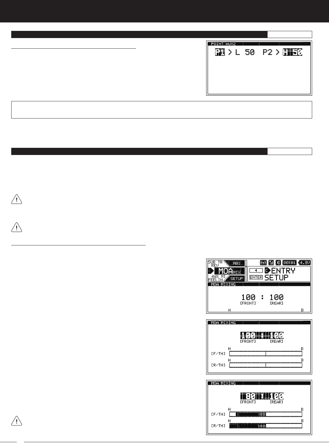
MOA MIX MENU {MOTOR ON AXLE MIXING}SETUP
The Motor on Axle Mixing function provides you with two Throttle channels. It is typically used for Rock Crawlers and allows you
to control either the Front and Rear motors together or independently, giving you Dig and Burn functions. In addition, you can
variably change the power distribution between the Front and Rear motors, allowing you the utmost in functionality.
Use one of the five Trim Switches, the Auxiliary Dial or the Auxiliary Lever to Activate the Dig and Burn functions while you're
driving.
When using the Motor on Axle function, it's important to adjust the F/TH channel and R/TH channel Sub-Trim values so
both motors are OFF when the Throttle Trigger is in the Neutral Point. In addition, remember, you are able to adjust many
functions, such as Exponential, Servo Speed and much more for each Throttle channel independently to allow for the optimum
Motor on Axle Mixing setup.
The Motor on Axle Mixing function is available only when either Car Type IX or Car Type X is Selected.
1) From within the SETUP menu, scroll UP or DOWN to highlight the MOA MIX
menu.
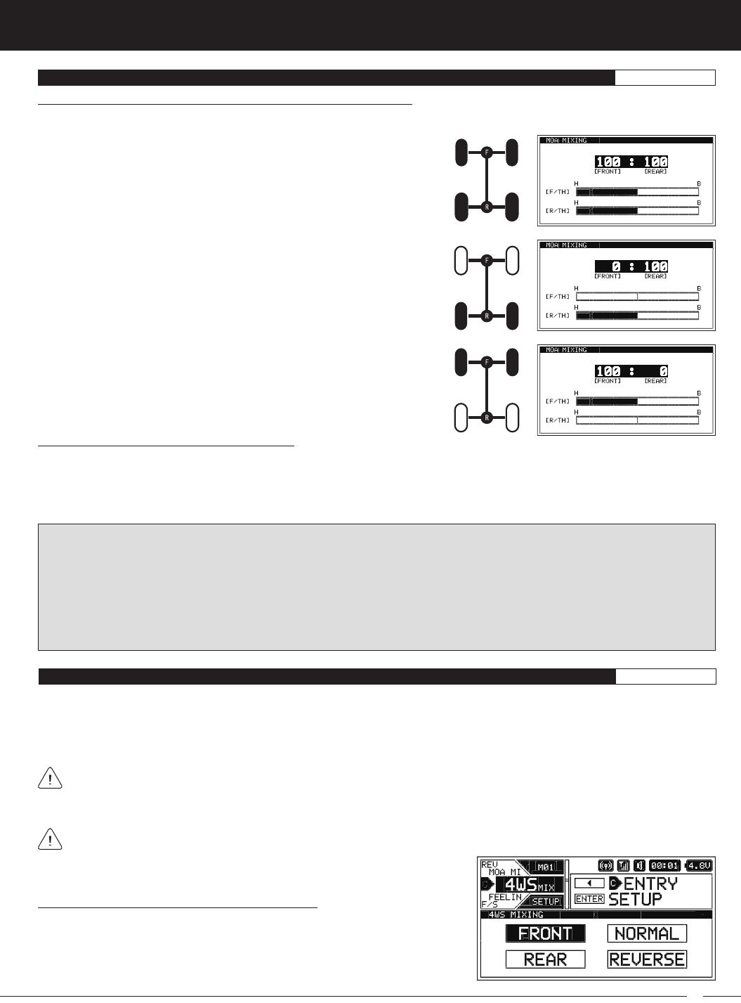
2) Press the ENTER key to open the MOA MIX menu. 100 [FRONT] : 100 [REAR]
will be highlighted.
3) Press the ENTER key, then scroll UP or DOWN to change the Power Distribution
between the Front and Rear motors. Reducing the [REAR] value will reduce
the available power to the Rear motor (Dig) and reducing the [FRONT] value
will reduce the power to the Front motor (Burn).
Use the Servo Monitor at the bottom of the MOA MIXING screen to view
Throttle channel output.
Choosing the Motor on Axle Power Distribution Values:
You are able to program Dig and Burn functions by changing the Power Distribution between the two motors. When both Front
and Rear values are balanced, Dig and Burn functions are Inhibited.
67
M12S 2.4GHZ FH4T RADIO CONTROL SYSTEM USER'S GUIDE
TR
Choosing the Four Wheel Steering Mixing Options:
1) From within the SETUP menu, scroll UP or DOWN to highlight the 4WS MIX
menu.
Controlling the Motor on Axle Mixing Function:
1) In order to control the Motor on Axle function, the MOA MIX function must be Assigned to either one of the five Trim Switches,
the Auxiliary Dial or the Auxiliary Lever. For more information, see the
ASSIGN Menu
section on pages 33 ~ 38.
2) Use the Trim Switch, Auxiliary Dial or Auxiliary Lever to adjust the Power Distribution values to achieve the desired results - either
OFF, Dig or Burn, as described above. A pop-up window will display the current Power Distribution values.
PRO TIP: In the default configuration, switching between OFF, Dig and Burn will happen gradually as you move the Trim Switch
or Auxiliary Dial. This allows you to vary the Power Distribution between the Front and Rear motors. If you prefer to switch
between OFF, Dig and Burn as if they were Assigned to an ON/OFF switch, change the Trim Switch or Auxiliary Dial Step value
to 100. For more information, see the
ASSIGN Menu
section on pages 33 ~ 38.
Alternately, switching between OFF, Dig and Burn can be controlled using the Auxiliary Lever. This allows you to quickly switch
between OFF, Dig and Burn and still have the ability to variably change the Power Distribution between the Front and Rear
motors. To set this up, Assign MOA MIX to the Auxiliary Lever, then change the TWEAK (H) value to +100 and the TWEAK (L)
value to -100. For more information, see the
ASSIGN Menu
section on pages 33 ~ 38.
MOA MIX MENU {MOTOR ON AXLE MIXING}SETUP
REAR Throttle (BURN) - When set to 0:100, power will only be distributed
to the Rear motor. Power can be distributed proportionally between the
Front and Rear motors from 0:100 to 99:100.
FRONT Throttle (DIG) - When set to 100:0, power will only be distributed
to the Front motor. Power can be distributed proportionally between the
Front and Rear motors from 100:0 to 100:99.
OFF (Balanced) - When set to 100:100 or other balanced value, power
will be evenly distributed between the Front and Rear motors.
Choosing the Motor on Axle Power Distribution Values, Continued....
The following Motor on Axle Mixing options can be programmed by changing the Power Distribution values:
4WS MIX MENU {FOUR WHEEL STEERING MIXING}SETUP
The Four Wheel Steering Mixing function provides you with two Steering channels. It allows you to control either the Front or Rear
Steering independently or Mix the Front and Rear Steering to have Parallel Four Wheel Steering (Crab) or Tandem Four Wheel
Steering. Use one of the five Trim Switches or the Auxiliary Dial to cycle through the different Four Wheel Steering options while
you're driving. The Four Wheel Steering Mixing function can be toggled OFF and ON while you're driving by Assigning 4WS to
one of the three Push-Button Switches.
When using the Four Wheel Steering function, it's important to adjust the F/ST channel and R/ST channel Sub-Trim values
to center both Steering servos when the Steering Wheel is centered. This will ensure that your Model tracks straight. In
addition, remember, you are able to adjust many functions, such as Exponential, Servo Speed and much more for each Steering
channel independently. This allows for the optimum Four Wheel Steering Mixing setup.
The Four Wheel Steering Mixing function is available only when either Car Type VIII or Car Type X is Selected.
68
M12S 2.4GHZ FH4T RADIO CONTROL SYSTEM USER'S GUIDE
4WS MIX MENU {FOUR WHEEL STEERING MIXING}SETUP
Choosing the Four Wheel Steering Mixing Options, Continued....
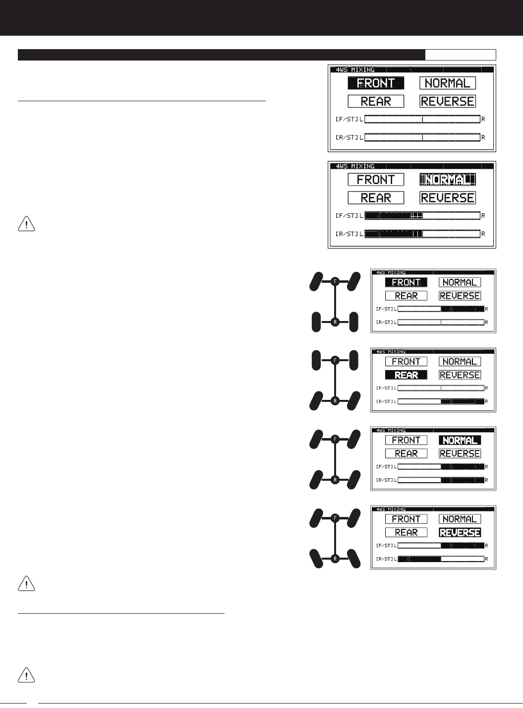
2) Press the ENTER key to open the 4WS MIX menu. The last Four Wheel Steering
Mixing option Selected will be highlighted.
3) Press the ENTER key, then scroll UP or DOWN to highlight the Four Wheel
Steering Mixing option you would like to use.
4) Press the ENTER key to Activate that option.
Use the Servo Monitor at the bottom of the 4WS MIXING screen to view
Steering channel output.
The following Four Wheel Steering Mixing options are available:
REAR Wheel Steering - When Active, only the Rear Steering will operate.
NORMAL (Parallel/Crab) Four Wheel Steering - When Active, both the
Front and Rear Steering will operate in Parallel.
REVERSE (Tandem) Four Wheel Steering - When Active, both the
Front and Rear Steering will operate in Tandem.
FRONT Wheel Steering - When Active, only the Front Steering will
operate.
If the Steering servos do not operate as described above, you can use the Servo Reversing function to change the direction
that each servo operates. For more information, see the
REV Menu
section on page 64.
Controlling the Four Wheel Steering Mixing Function:
1) In order to control the Four Wheel Steering function, the 4WS MIX function must be Assigned to either one of the five Trim
Switches or the Auxiliary Dial. For more information, see the
ASSIGN Menu
section on pages 33 ~ 38.
2) Use the Trim Switch or Auxiliary Dial to cycle through the various Four Wheel Steering Mixing options. A pop-up window will
display the currently Active option.
The Step value for the Trim Switch or Auxiliary Dial should be set to 1, otherwise the transmitter won't cycle properly through
the Four Wheel Steering Mixing options. For more information, see the
Changing the Trim Switch Step Value
section on
page 35 or the
Changing the Auxiliary Dial Step Value
section on pages 36 ~ 37.
69
M12S 2.4GHZ FH4T RADIO CONTROL SYSTEM USER'S GUIDE
TR
FEELING MENU {STEERING AND THROTTLE CHANNEL RESPONSE TIME}SETUP
The Feeling function allows you to adjust the Response Time of the Steering and Throttle channels to fine-tune the sensitivity of
these controls. The M12S transmitter has an extremely fast Response Time (Latency), which results in the driver feeling extremely
connected to their Model. This ultra-fast Response Time can be felt by the racer, particularly during on-road racing where the vehicle
reacts extremely quickly to control inputs due to the increased traction between the vehicle and the track. After getting used to
this fast Response Time, it allows for quicker, smoother control of your Model, which gives you an advantage over other drivers.
Some users may find that the Response Time is in some cases too fast, therefore, we've made it adjustable to suit the driver's
driving style, Car Type and track conditions.
The Feeling function works not only with Airtronics FH4T and FH4 receivers, but also with FH3 and FH2 receivers as well.
Changing Steering and Throttle Response Time Values:
1) From within the SETUP menu, scroll UP or DOWN to highlight the FEELING
menu.
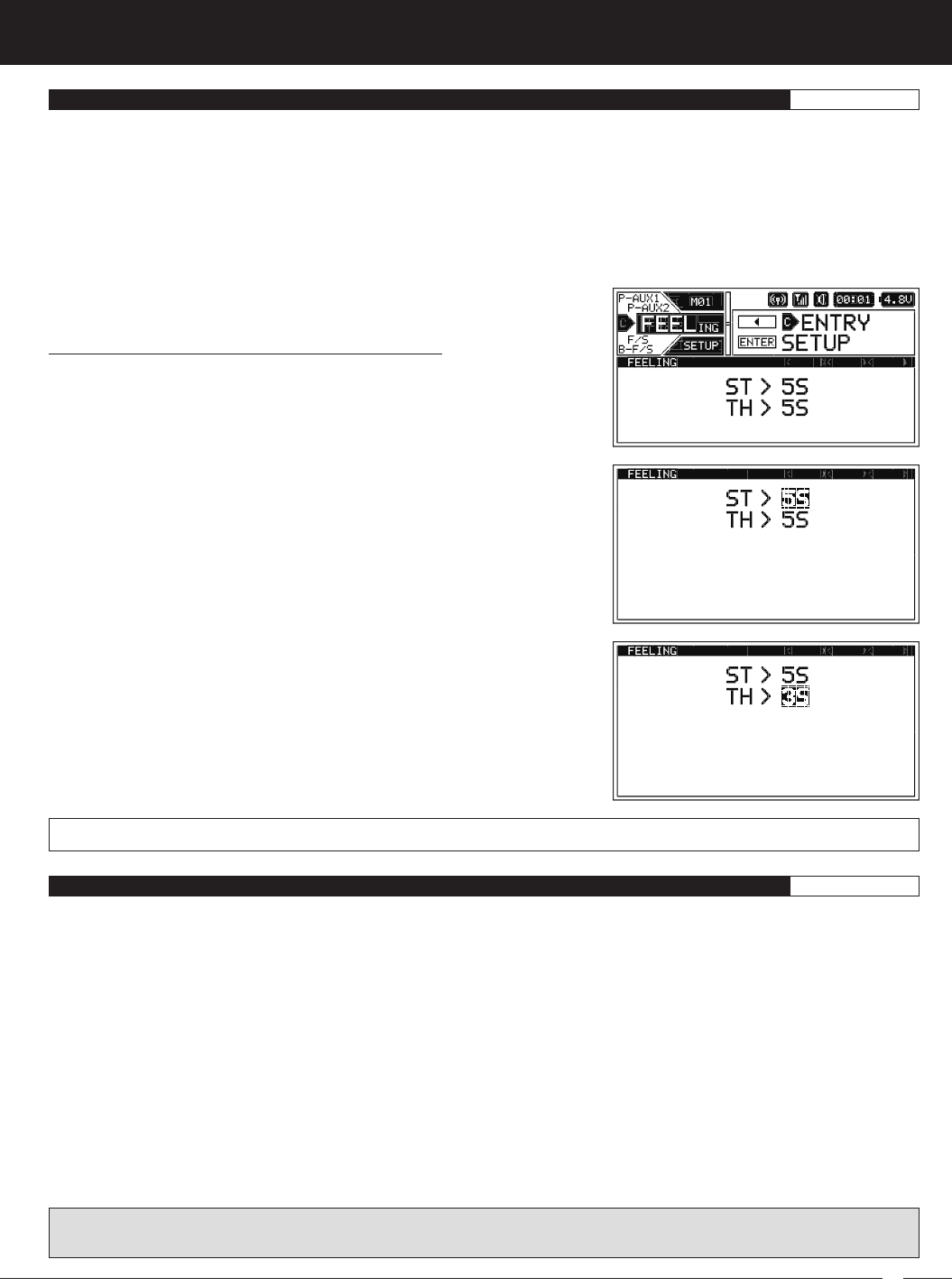
2) Press the ENTER key to open the FEELING menu. ST > 5S will be highlighted.
3) Scroll UP or DOWN to highlight the desired channel you would like to change
the Response Time value for, either ST (Steering) or TH (Throttle).
4) Press the ENTER key, then scroll UP or DOWN to choose the desired Response
Time value for that channel. When set to 0, Response Time is similar to the
Airtronics M11X (approximately 5ms average). Increasing the 'S' value
Increases Response Time and Increasing the 'F' value Decreases Response Time.
ST and TH setting range is 5S to 1S, 0 and 1F to 5F. The default setting is 5S.
F /S {FAIL SAFE}SETUP
The Fail Safe function automatically moves the servos to a predetermined position in the event that the signal between the
transmitter and the receiver is interrupted, whether due to signal degradation or to low transmitter battery.
Several different options are available. The Fail Safe function can be set to HOLD the servos in the last position they were in when
the signal was lost or each of the servos can be set to move to a custom position when the signal is lost. For example, the Throttle
servo (or ESC) can be programmed to move toward the Brake Side to engage the Brakes and stop your Model, or, if you're
driving a gas- or glow-powered boat, the Fail Safe function could be set to Lower the Throttle servo (or ESC) to idle and turn the
rudder slightly Left or Right so that the boat will continue in slow circles.
Fail Safe settings can be programmed for each of the four channels individually. In addition, Fail Safe settings are Model-specific,
meaning you can have different Fail Safe settings for each of your Models. The Fail Safe settings will be retained even if the
transmitter loses power or if the transmitter and receiver must be paired again.
Three Fail Safe options are available for each channel as described below:
FREE - Fail Safe is Disabled for this channel. Servos can move freely when the signal is lost.
HOLD - When Fail Safe Activates, the servo will be held in the last position it was in when the signal was lost.
% (PERCENTAGE) - When Fail Safe Activates, the servo will travel to the programmed position when the signal is lost.
WARNING: The Fail Safe function will NOT OPERATE if the receiver loses power. For example, if the receiver battery were to
die or come unplugged. It will operate only if the transmitter and receiver signal is interrupted or if the transmitter loses power.