Sanwa Electronic Instrument Co 90486 2.4GHz Radio Control System User Manual 4
Sanwa Electronic Instrument Co Ltd 2.4GHz Radio Control System 4
Contents
- 1. User Manual-1
- 2. User Manual-2
- 3. User Manual-3
- 4. User Manual-4
- 5. User Manual-5
User Manual-4

70
M12S 2.4GHZ FH4T RADIO CONTROL SYSTEM USER'S GUIDE
Changing the Fail Safe Settings:
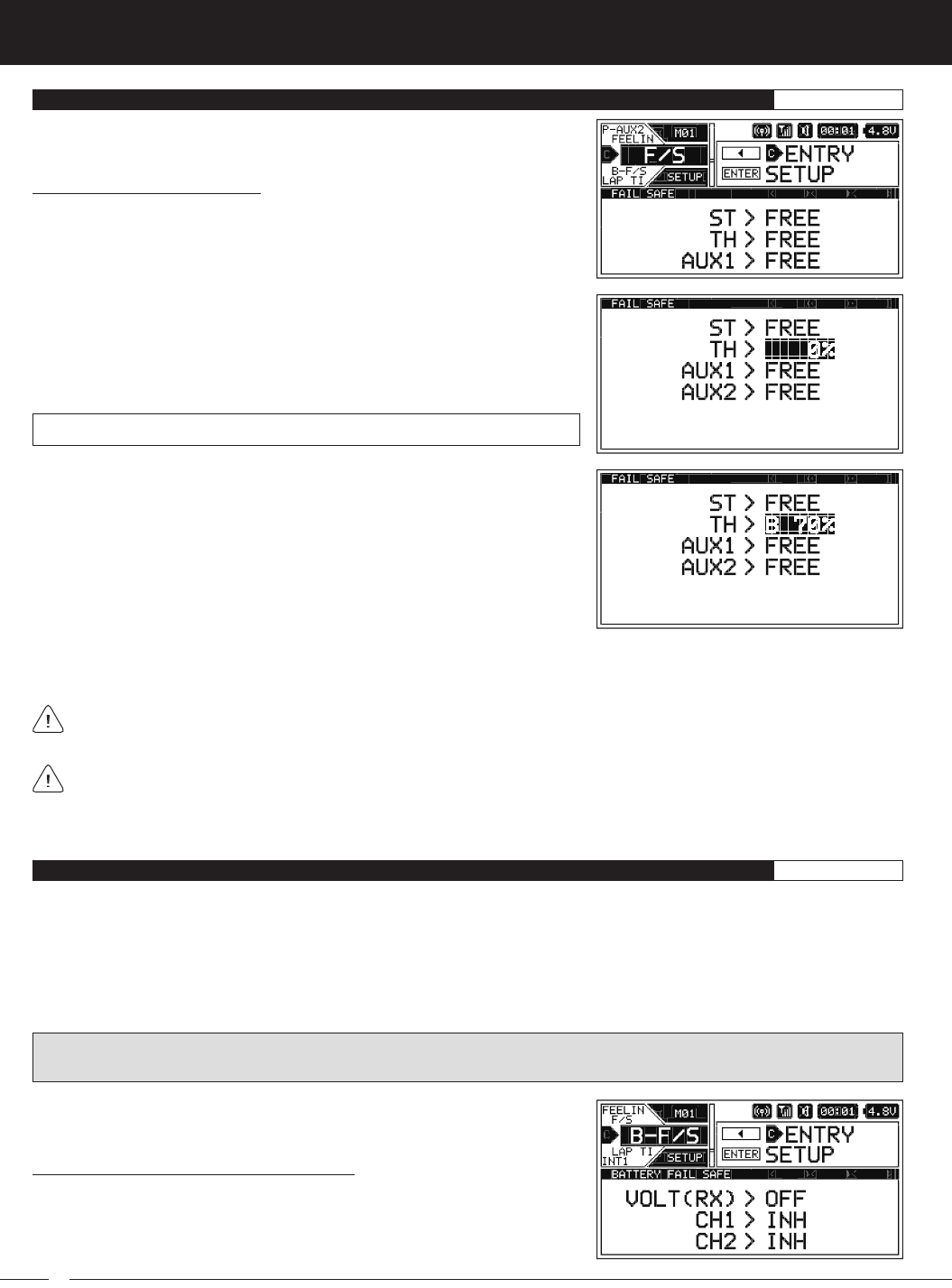
1) From within the SETUP menu, scroll UP or DOWN to highlight the F/S menu.
2) Press the ENTER key to open the F/S menu. ST > FREE will be highlighted.
3) Scroll UP or DOWN to highlight the desired channel you would like to change
the Fail Safe value for.
4) Press the ENTER key, then scroll UP or DOWN to choose the desired Fail Safe
value for that channel. If you choose to program a % value, see step 5 below.
F/S setting range is FREE, HOLD or %. The default setting for all channels is FREE.
5) To program a Fail Safe % value, move the transmitter control (e.g., Throttle
Trigger) the desired amount, then press and HOLD the ENTER key until an
audible Tone sounds. The direction and percentage the servo will travel will
be displayed. For example, to set the Brakes to Engage when the Fail Safe
function Activates, push the Throttle Trigger toward the Brake Side the desired
amount, HOLD the Throttle Trigger in that position, then press and HOLD the
ENTER key.
6) Check to ensure your Fail Safe settings are working properly. Make sure that both the transmitter and receiver are turned ON,
then, while someone is holding your Model, turn the transmitter OFF. The servos should react correctly based on the Fail Safe
values chosen.
When using an FH2 receiver with your transmitter, these Fail Safe features are not supported. In this case, the Fail Safe
function must be programmed directly through the receiver. For more information, follow the Fail Safe Programming
instructions provided with your FH2 receiver.
If using a Car Type that features two Steering channels or two Throttle channels (like a Rock Crawler) and you're programming
a Fail Safe % value, we suggest setting one of the Steering or Throttle channels to FREE and the other Steering or Throttle
channels to the desired Fail Safe % value. This will ensure one of the channels won't be fighting the other duplicate channel
should the Fail Safe function Activate.
F /S {FAIL SAFE}SETUP
B - F /S {RECEIVER BATTERY VOLTAGE FAIL SAFE}SETUP
The Receiver Battery Voltage Fail Safe function is designed to alert you when your receiver battery requires recharging. This
ensures that the receiver battery's voltage doesn't drop so low that your servos aren't provided adequate voltage to operate
optimally. When Activated, the servo(s) will move to the predetermined position that you programmed in step 5 in the
Changing
the Fail Safe Settings
section to indicate your receiver battery's voltage has dropped below the programmed Voltage value.
When used with an FH4 or FH4T receiver, the Receiver Battery Voltage Fail Safe function can be Activated for all four channels
independently. When used with an FH3 receiver, the Receiver Battery Voltage Fail Safe function can be Activated only for the
Throttle channel. The Receiver Battery Voltage Fail Safe function cannot be used with FH2 receivers.
WARNING: This function is designed for use with glow- or gas-powered Models that use a separate receiver battery pack. Do
NOT use this function with an electric Model that uses the motor battery to power the servos and receiver.
Choosing the Receiver Battery Voltage Value:
1) From within the SETUP menu, scroll UP or DOWN to highlight the B-F/S menu.

71
M12S 2.4GHZ FH4T RADIO CONTROL SYSTEM USER'S GUIDE
TR
Choosing the Receiver Battery Voltage Value, Continued....
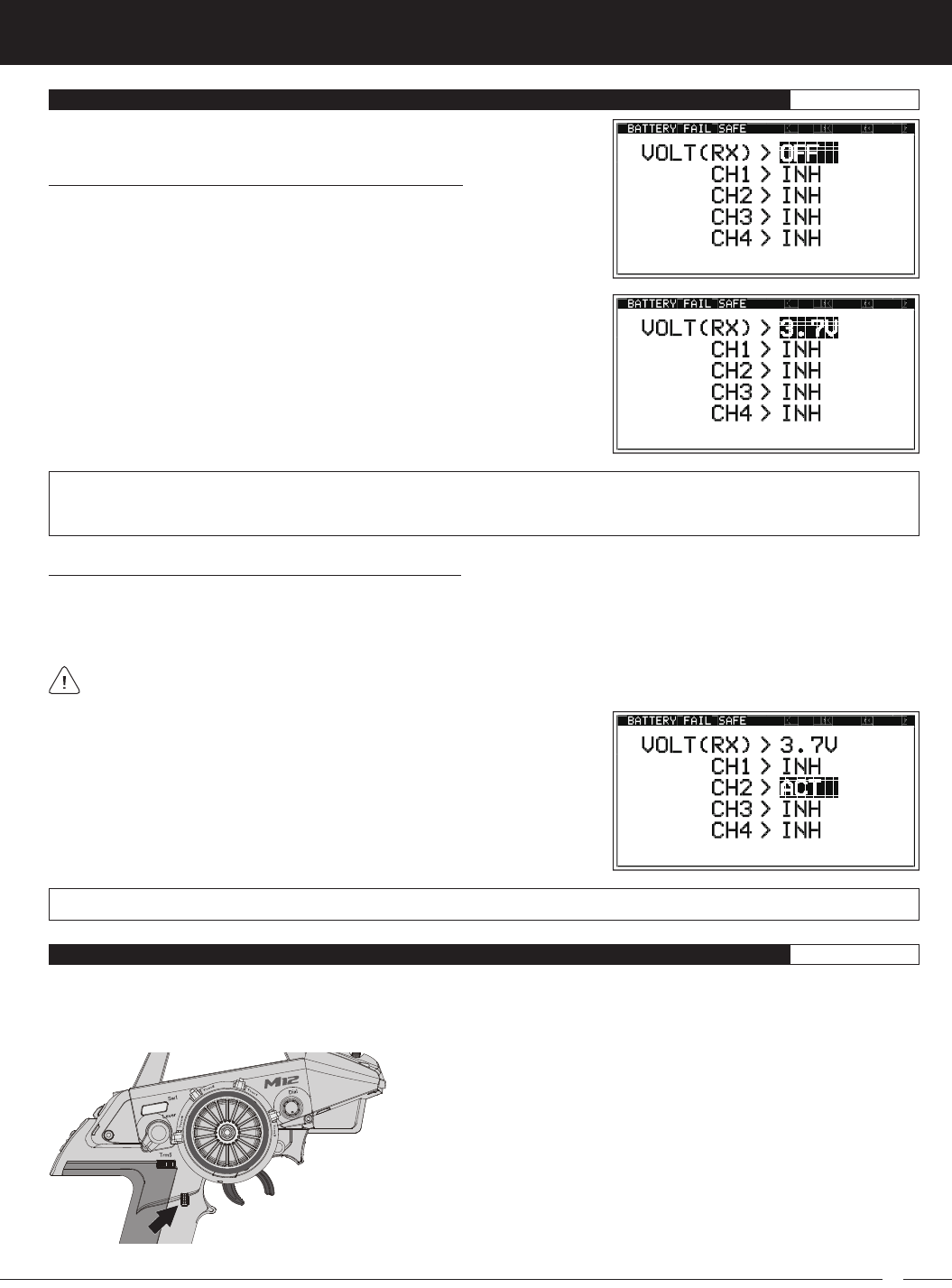
2) Press the ENTER key to open the B-F/S menu. VOLT (RX) > OFF will be
highlighted.
VOLT (RX) setting range for FH4 and FH4T receivers is OFF and 3.5V to 7.4V. VOLT (RX) setting range for FH3 receivers is
OFF and 3.5V to 5.0V. The default setting is OFF regardless of the Modulation Type chosen. Use with FH2 receivers is not
supported.
3) Press the ENTER key, then scroll UP or DOWN to choose the desired Receiver
Battery Voltage value. Many factors, such as the current draw of your servos
and how many servos you're using, etc., will determine the value to use. A
good starting point would be 3.7V. If it appears your servos are slow or not
producing adequate torque what that Voltage value is reached, Increase the
Voltage value.
Activating the Receiver Battery Voltage Fail Safe Function:
The Receiver Battery Fail Safe function can be Activated for one or more channels, however, in most cases you will want
to Activate this function only for the Throttle channel. When Activated, the Throttle servo will move to the predetermined position
that you programmed in step 5 in the
Choosing Fail Safe Settings
section to indicate your receiver battery's voltage has dropped
below the programmed Voltage value. When this happens, stop using your Model and recharge the receiver battery.
A % value must be Selected to be able to Activate the Receiver Battery Voltage Fail Safe function. If FREE or HOLD is
Selected for any of the channels, you cannot Activate the Receiver Battery Voltage Fail Safe function.
1) From within the B-F/S menu, scroll UP or DOWN to highlight desired channel
number you want to Activate the Receiver Battery Voltage Fail Safe function for.
2) Press the ENTER key, then scroll UP or DOWN to choose the desired Battery
Fail Safe value, either ACT or INH.
3) Press the ENTER key, then repeat steps 1 and 2 to change any other desired
Battery Fail Safe values.
CH1, CH2, CH3 and CH4 setting range is INH and ACT. The default setting for all channels is INH.
B - F /S {RECEIVER BATTERY VOLTAGE FAIL SAFE}SETUP
LAP TIMER MENU {VIEW LAP TIMES AND CHOOSE LAP TIMER OPTIONS}SETUP
The Lap Timer function allows you to measure and record Lap Times for up to 250 Laps. The total number of Laps, the Current Lap
Time, the Best Lap Time and the Average Lap Time are all displayed. After the Lap Timer is Stopped, the Cumulative Time will be
displayed. Lap Times are displayed in the following format: 00':00".00 (Minutes : Seconds : 1/100th of a Second).
In addition to being able to view Lap Times, a Goal Time function is featured
that will sound when you reach your Goal Time. For example, you can set
the Goal Time value to the total time you would like to finish your race under.
If desired, a Pre-Alarm function can be programmed to Alert you to your
upcoming Goal Time.
Lap Times can be viewed within the LAP TIMER menu or on the TELEMETRY
screen ALL and LAP pages. In addition, a pop-up window will display when
the Lap Timer Starts and Stops, and each time a Lap Time is counted.
In the default configuration, placing the Lap Timer in Standby, Starting and
Stopping the Lap Timer, and counting Lap Times, is controlled using the Lap
Timer Switch (Push-Button Switch Sw3). In addition, if desired, the Throttle
Trigger can be used to Start the Lap Timer after it's been placed in Standby.

72
M12S 2.4GHZ FH4T RADIO CONTROL SYSTEM USER'S GUIDE
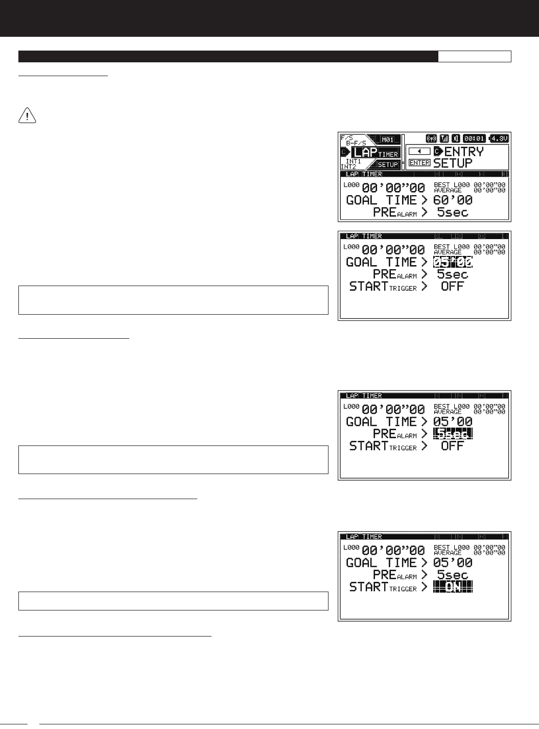
1) From within the SETUP menu, scroll UP or DOWN to highlight the LAP TIMER
menu.
2) Press the ENTER key to open the LAP TIMER menu. GOAL TIME > 60'00 will be
highlighted.
3) Press the ENTER key, then scroll UP or DOWN to choose the desired Goal
Time value in Minutes : Seconds.
GOAL TIME setting range is 10 Seconds to 60 Minutes (00'10 to 60'00) and is
adjustable in 10 second intervals. The default setting is 60 Minutes.
Setting the Pre-Alarm Time:
The Pre-Alarm function is used to alert you that your Goal Time is approaching. You can program the Pre-Alarm to sound once
every second the desired number of seconds prior to reaching your Goal Time. For example, if the Pre-Alarm value is set to
5 Seconds, a short audible Tone will sound every second, 5 seconds prior to reaching your Goal Time. If desired, the Pre-Alarm
value can be set to OFF to turn the Pre-Alarm OFF.
1) From within the LAP TIMER menu, scroll UP or DOWN to highlight PREALARM
> 5sec.
2) Press the ENTER key, then scroll UP or DOWN to choose the desired Pre-Alarm
value in Seconds.
PREALARM setting range is OFF and 1 to 20 Seconds. The default setting is
5 Seconds.
Choosing the Optional Throttle Trigger Start:
The Throttle Trigger can be used to Start the Lap Timer after the Lap Timer as been placed in Standby. This is much more convenient
than worrying about pressing the Lap Timer Switch again to Start the Lap Timer when you're starting your race.
1) From within the LAP TIMER menu, scroll UP or DOWN to highlight
STARTTRIGGER > OFF.
2) Press the ENTER key, then scroll UP or DOWN to choose the desired Start
Trigger value, either ON of OFF.
STARTTRIGGER setting range is OFF and ON. The default setting is OFF.
Setting the Goal Time:
When the Lap Timer is counting Up, a long audible Tone will sound when the Goal Time is reached. For example, if you set the
Goal Time value for 5 Minutes, a long audible Tone will sound when the Lap Timer reaches 5 minutes.
When the Goal Time is reached the Lap Timer will continue counting Up, but you will no longer be able to continue counting
Lap Times. The next time you press the Lap Timer Switch, the Lap Timer will Stop.
LAP TIMER MENU {VIEW LAP TIMES AND CHOOSE LAP TIMER OPTIONS}SETUP
Starting the Lap Timer and Counting Lap Times:
1) In the default configuration, the Lap Timer Switch (Push-Button Switch Sw3) controls the Lap Timer. Press and HOLD the Lap
Timer Switch for 3 seconds. An audible Double-Tone will sound and LAP [STANDBY] will be displayed momentarily in a pop-up
window, indicating the Lap Timer is in Standby. To start the Lap Timer, press the Lap Timer Switch a second time or pull the Throttle
Trigger if you've Enabled the Start Trigger function. An audible Double-Tone will sound and the Lap Timer will start counting Up.
2) Press the Lap Timer Switch a second time to store the first Lap Time and begin counting a second Lap Time. Each time you
press the Lap Timer Switch, an audible Tone sounds, the previous Lap Time is stored, a new Lap Time begins and the current
Lap Time is displayed momentarily in a pop-up window.