Sanwa Electronic Instrument Co 90486 2.4GHz Radio Control System User Manual 5
Sanwa Electronic Instrument Co Ltd 2.4GHz Radio Control System 5
Contents
- 1. User Manual-1
- 2. User Manual-2
- 3. User Manual-3
- 4. User Manual-4
- 5. User Manual-5
User Manual-5
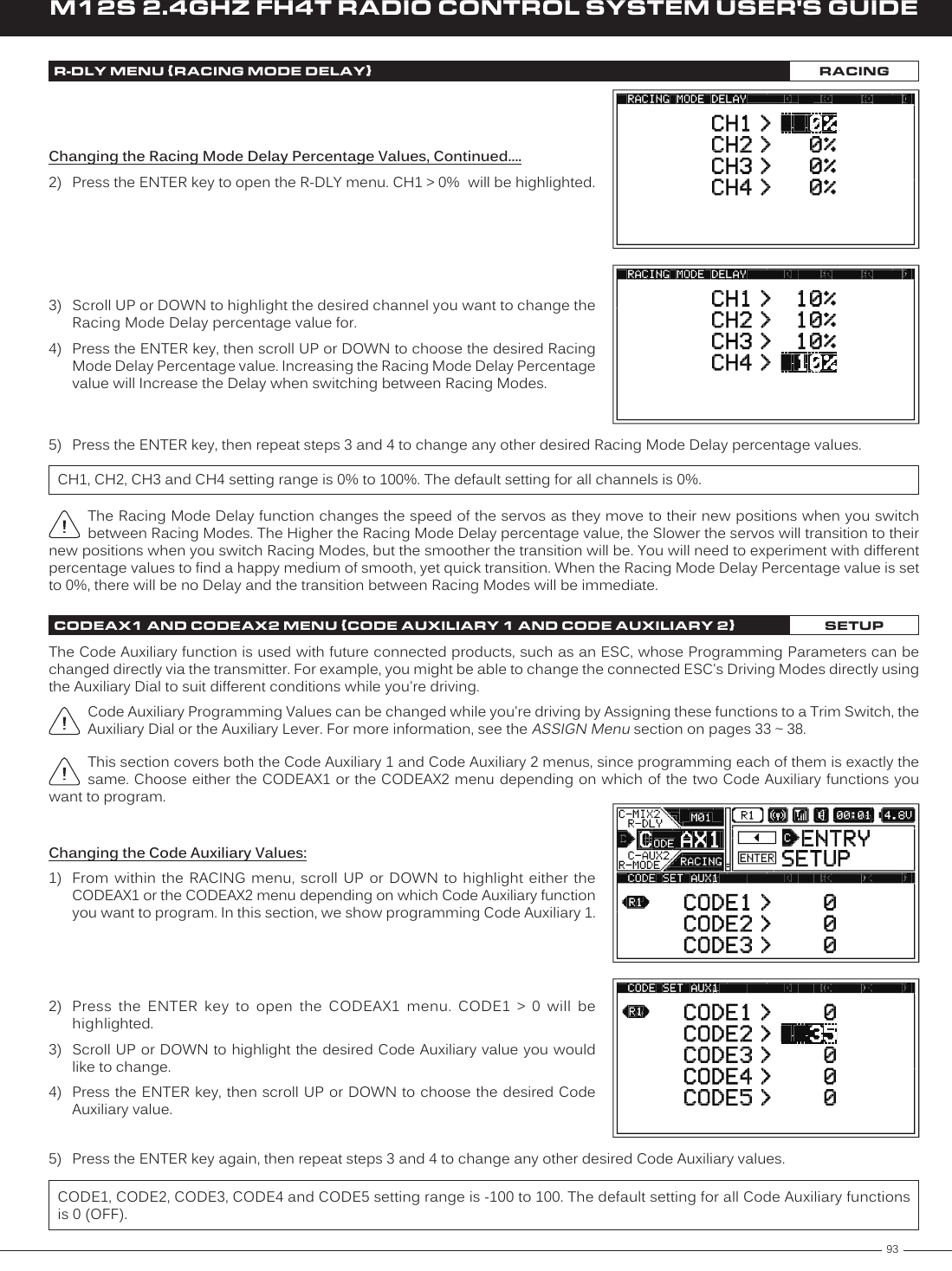
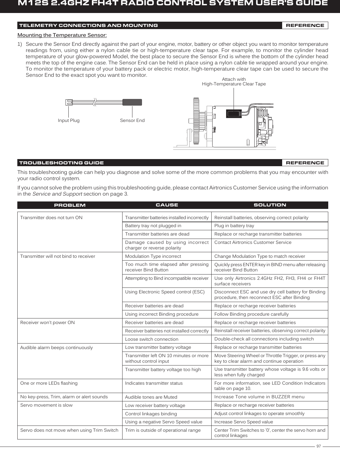
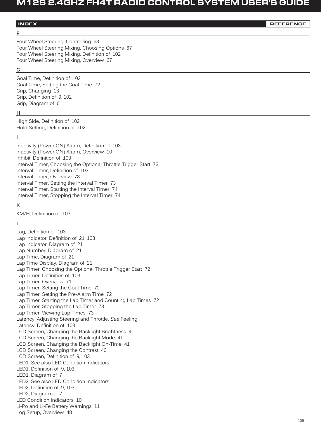
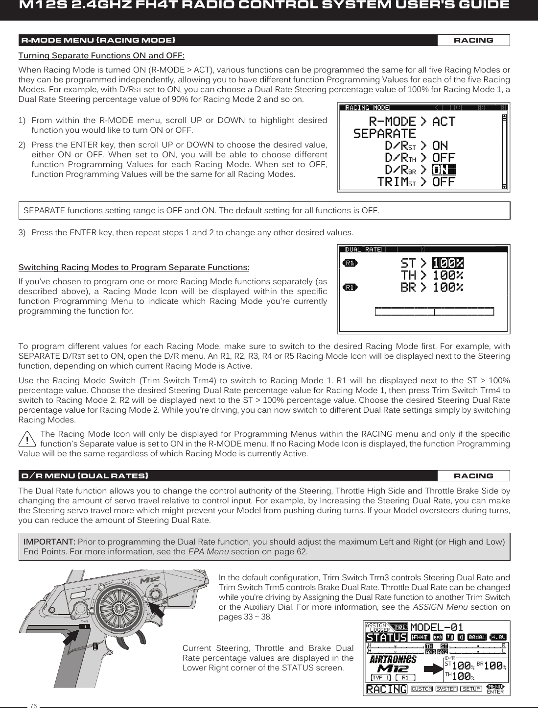
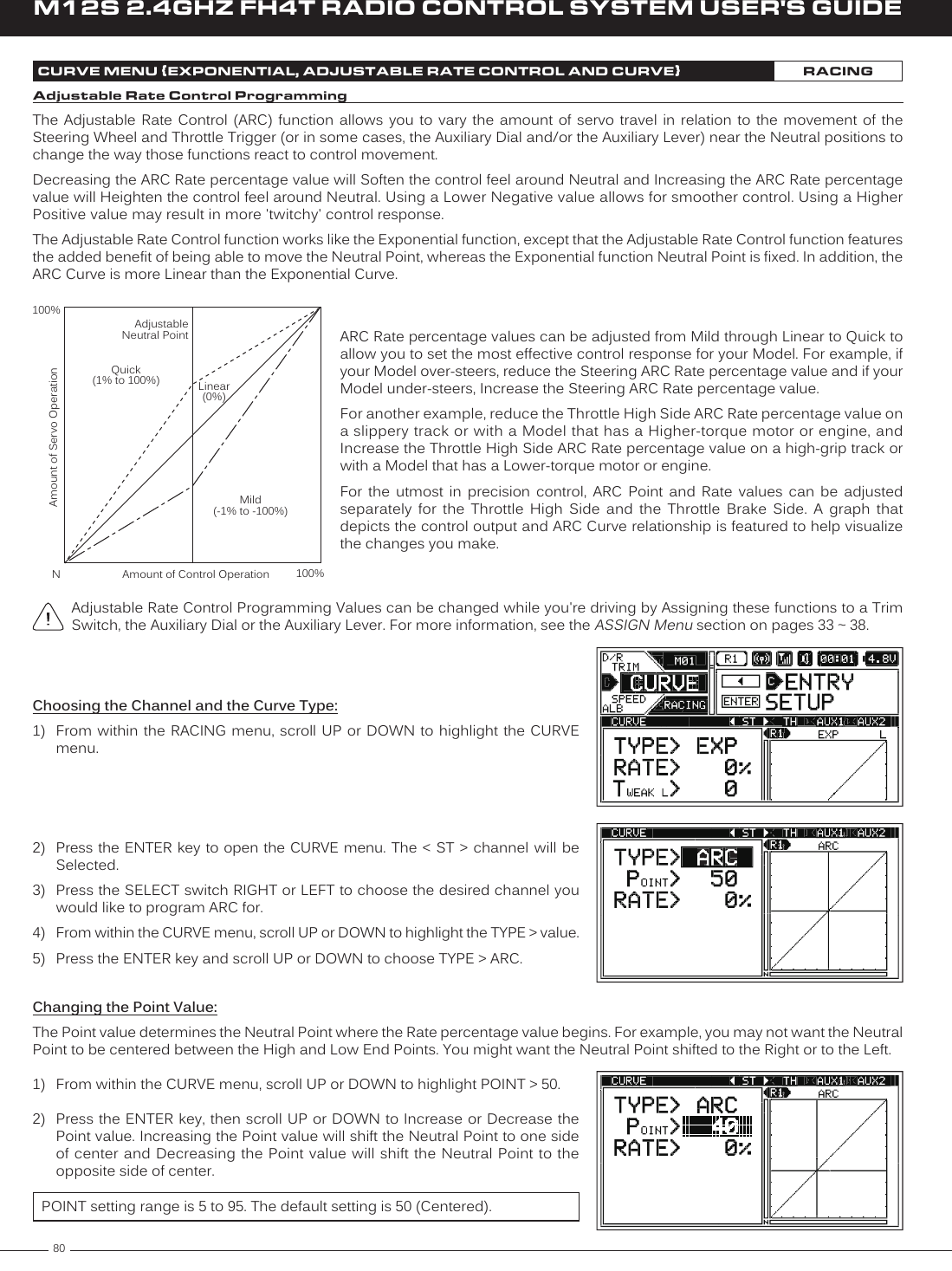
![73M12S 2.4GHZ FH4T RADIO CONTROL SYSTEM USER'S GUIDETRLAP TIMER MENU {VIEW LAP TIMES AND CHOOSE LAP TIMER OPTIONS}SETUPStopping the Lap Timer:1) To Stop the Lap Timer, press and HOLD the Lap Timer Switch for 3 seconds. An audible Double-Tone will sound and LAP [STOPPED] will be displayed momentarily in a pop-up window, indicating the Lap Timer is stopped.The Cumulative Time cannot be manually cleared. It will be automatically cleared when the Lap Timer is put in Standby again.Viewing Lap Times:The Cumulative Lap Time, the Best Lap Time and the Average Lap Time, in addition to up to 250 individual Lap Times can be viewed on the TELEMETRY screen LAP page. 1) From the STATUS screen, scroll UP or DOWN to open the TELEMETRY screen. Press the SELECT switch Right or Left to open the LAP page.2) Press the ENTER key, then scroll UP or DOWN to view the individual Lap Times.Lap Times are stored until you Restart the Lap Timer. When the Lap Timer is Restarted, old Lap Times are Cleared and new Lap Times are Stored.INT1 AND INT2 MENU {INTERVAL 1 AND INTERVAL 2 TIMERS}SETUPThe Interval Timer function is used to notify you when a set Interval elapses while you're driving. When the Interval Time is reached, an audible Double-Tone will sound, then the Interval Timer will Reset and begin counting Up again from zero. Interval Times are displayed in the following format: 00':00".00 (Minutes : Seconds : 1/100th of a Second). The Interval Timer can be programmed to work independently or programmed to work along with the Lap Timer function.This section covers both the INT1 and INT2 menus, since programming each of them is exactly the same. Choose either the INT1 or the INT2 menu depending on which of the two Interval Timers you want to program. There are two Interval Timers. These Interval Timers can be Started and Stopped independently by Assigning each one to a different Push-Button Switch or they can be Started and Stopped simultaneously by Assigning both of them to the same Push-Button Switch. If desired, different Tones can be Assigned to each Interval Timer to differentiate them and the Throttle Trigger can be programmed to Start the Interval Timer(s).In the default configuration, Interval Timer 1 is Started and Stopped along with the Lap Timer, using the Lap Timer Switch (Push-Button Switch Sw3).Setting the Interval Timer:1) From within the SETUP menu, scroll UP or DOWN to highlight either the INT1 or the INT2 menu depending on which Interval Timer you want to program. In this section, we show programming Interval Timer 1.2) Press the ENTER key to open the INT1 menu. INTERVAL > 00' will be highlighted.3) Scroll UP or DOWN to highlight the desired Interval Timer value you would like to change, either 00' (Minutes) , 00" (Seconds) or 00 (1/100th Seconds).4) Press the ENTER key, then scroll UP or DOWN to choose the desired Interval Timer value.5) Press the ENTER key again, then repeat steps 3 and 4 to change any other desired Interval Timer values.INT1 and INT2 INTERVAL setting range is 00:00:00 to 99:59:90. The default setting for both Interval Timers is 00:00:00 (OFF). Choosing the Optional Throttle Trigger Start:The Throttle Trigger can be used to Start the Interval Timer after the Interval Timer as been placed in Standby. This is much more convenient than worrying about pressing the Interval Timer Switch again to Start the Interval Timer when you're starting your race.](https://usermanual.wiki/Sanwa-Electronic-Instrument-Co/90486.User-Manual-5/User-Guide-2587751-Page-1.png)
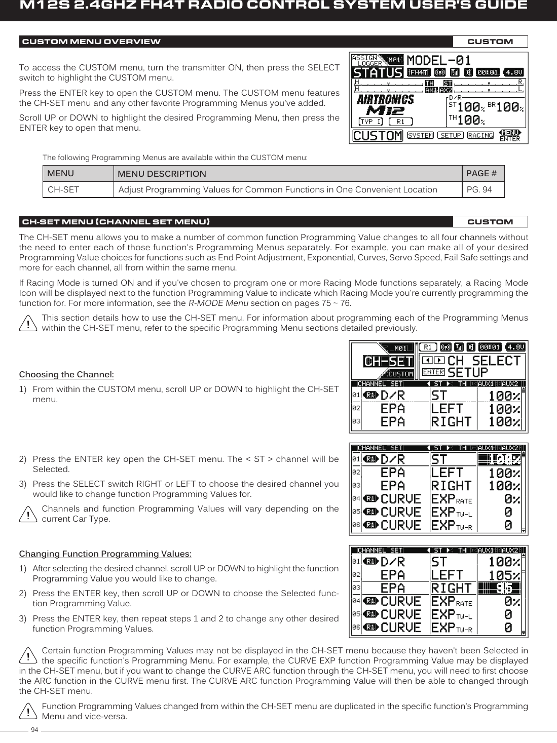
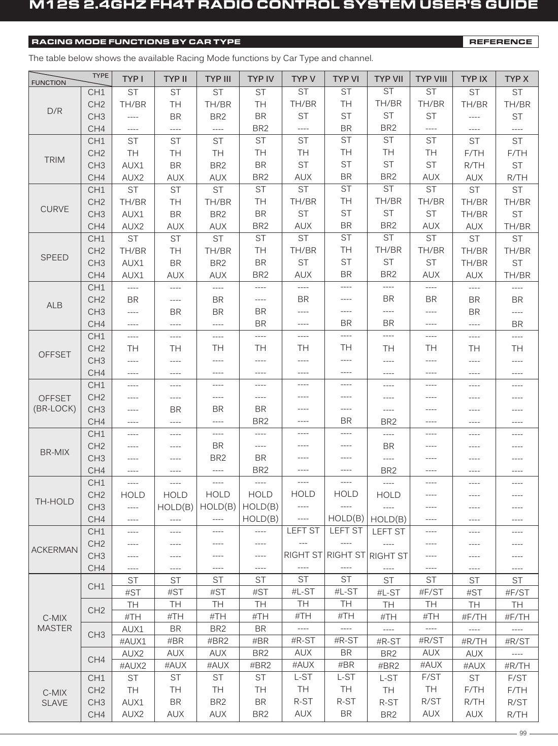
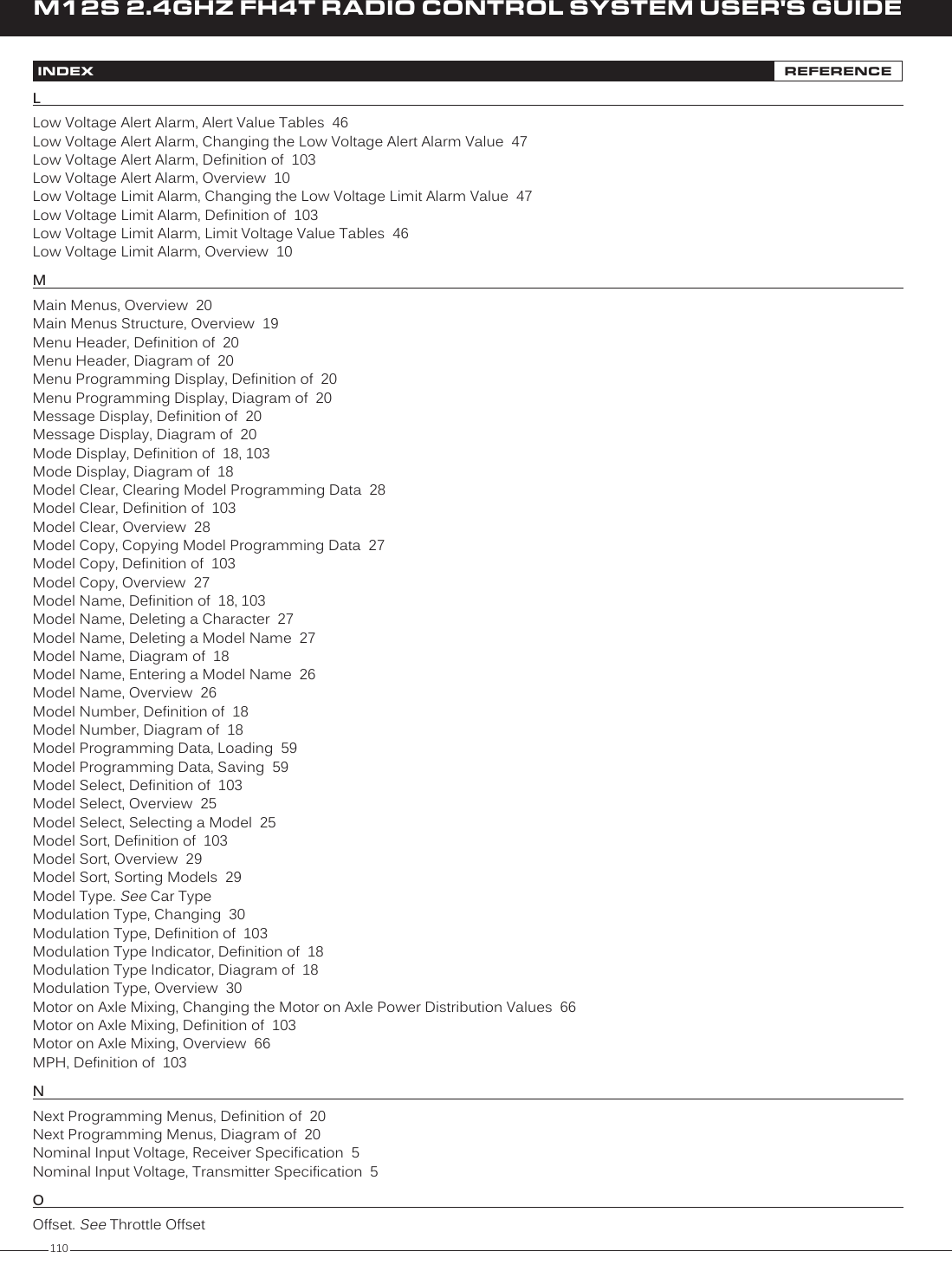
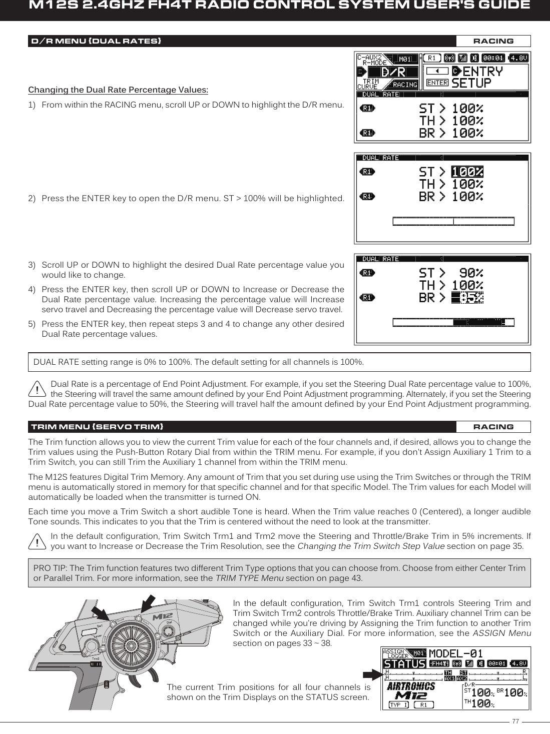
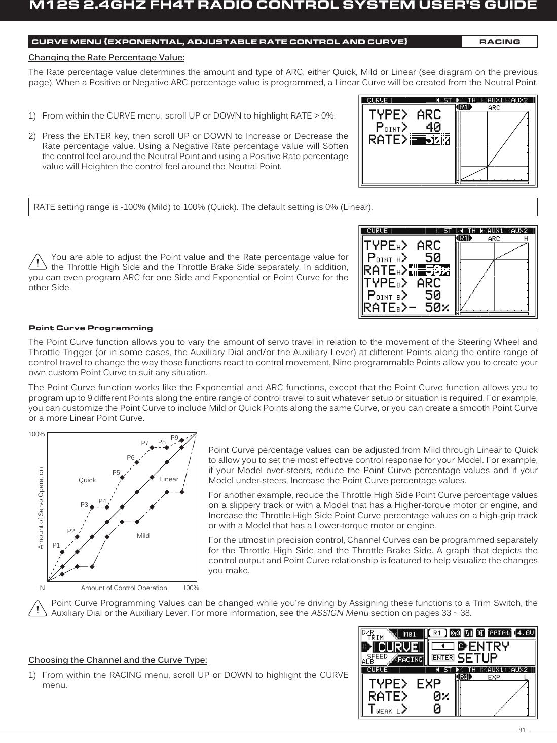
![74M12S 2.4GHZ FH4T RADIO CONTROL SYSTEM USER'S GUIDEChoosing the Optional Throttle Trigger Start, Continued....1) From within the INT1 menu, scroll UP or DOWN to highlight STARTTRIGGER > OFF.2) Press the ENTER key, then scroll UP or DOWN to choose the desired Start Trigger value, either ON of OFF.INT1 and INT2 STARTTRIGGER setting range is OFF and ON. The default setting for both Interval Timers is OFF. INT1 AND INT2 MENU {INTERVAL 1 AND INTERVAL 2 TIMERS}SETUPStarting the Interval Timers:In the default configuration, the Lap Timer Switch (Push-Button Switch Sw3) controls both the Lap Timer and Interval Timer 1. To control Interval Timer 2, it must first be Assigned to a Push-Button Switch. If desired, the Interval Timers can be Started and Stopped independently by Assigning each one to a different Push-Button Switch or they can be Started and Stopped simultaneously by Assigning both of them to the same Push-Button Switch. Regardless of what you decide, follow the step below to control the Interval Timer(s).1) Press and HOLD the Push-Button Switch you've Assigned the Interval Timer(s) to for 3 seconds. An audible Double-Tone will sound and INT1 [STANDBY] or INT2 [STANDBY] will be displayed momentarily in a pop-up window, indicating the Interval Timer is in Standby. To Start the Interval Timer, press the Push-Button Switch a second time or pull the Throttle Trigger if you've Enabled the Start Trigger function. An audible Double-Tone will sound and the Interval Timer will start counting Up. Each time the Interval Time elapses, an audible Double-Tone will sound and the Interval Timer will Reset and start counting Up again from zero. If desired, you can manually Restart the Interval Timer from zero by pressing the Push-Button Switch while the Interval Timer is running.If the Interval Timer is Assigned to the same Push-Button Switch as the Lap Timer and the Lap Timer is Assigned to Function 1, LAP will flash and Lap Time information will be displayed in a pop-up window, but the Interval Timer will run in the background.When both Interval Timers are Assigned to the same Push-Button Switch, only the Interval Timer Assigned to Function 1 will be displayed in the pop-up window when the Interval Timers Start and Stop, however, if the Interval Timers are set to different values, each Interval Timer will be displayed in the pop-up window as the Interval Times are reached.Stopping the Interval Timers:1) To stop the Interval Timer(s), press and HOLD the Push-Button Switch you've Assigned the Interval Timer(s) for 3 seconds. An audible Double-Tone will sound indicating the Interval Timer(s) is stopped.When Stopped, the Interval Timer will read 00'01"00. This is normal. This value will be cleared when the Interval Timer is placed in Standby again.R-MODED/RTRIMCURVESPEEDALBPG. 75PG. 76PG. 77PG. 78PG. 82PG. 84MENU PAGE #MENU DESCRIPTIONTurn Racing Mode ON or OFF and Choose Racing Mode OptionsAdjust Steering, Throttle and Brake Dual RatesAdjust Servo Trim, Including Auxiliary Channel TrimAdjust Channel Exponential, Adjustable Rate Control (ARC) and CurvesAdjust Servo Speed in the Forward and the Return to Neutral DirectionsTurn Anti-Lock Braking ON or OFF and Choose Anti-Lock Braking OptionsThe following Programming Menus are available within the RACING menu:To access the various RACING Programming Menus, turn the transmitter ON, then press the SELECT switch to highlight the RACING menu. Press the ENTER key to open the RACING menu.Scroll UP or DOWN to highlight the desired Programming Menu, then press the ENTER key to open that menu.Depending on the Car Type chosen, some Function Programming Value Names may differ from those shown in this section.RACING MENU OVERVIEW RACING](https://usermanual.wiki/Sanwa-Electronic-Instrument-Co/90486.User-Manual-5/User-Guide-2587751-Page-2.png)
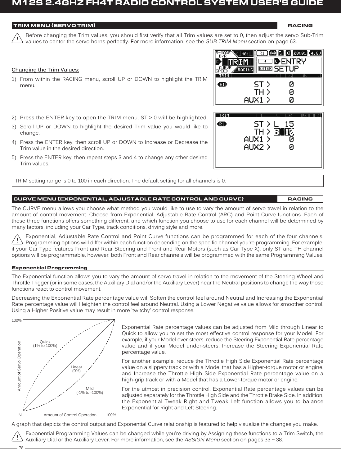
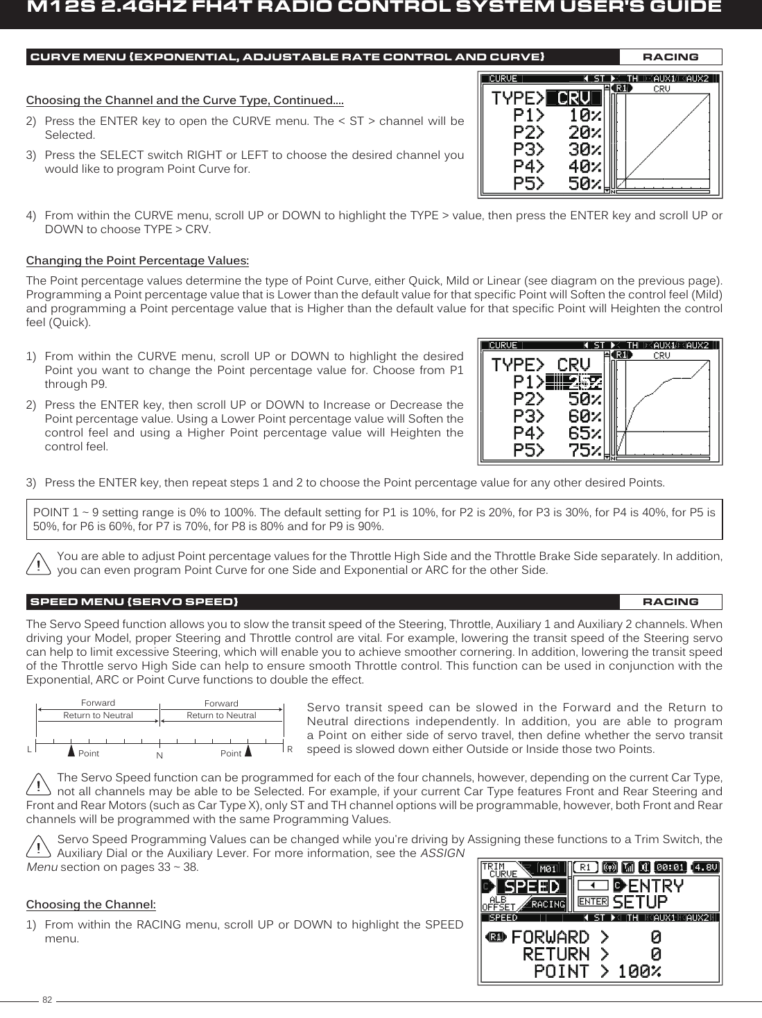
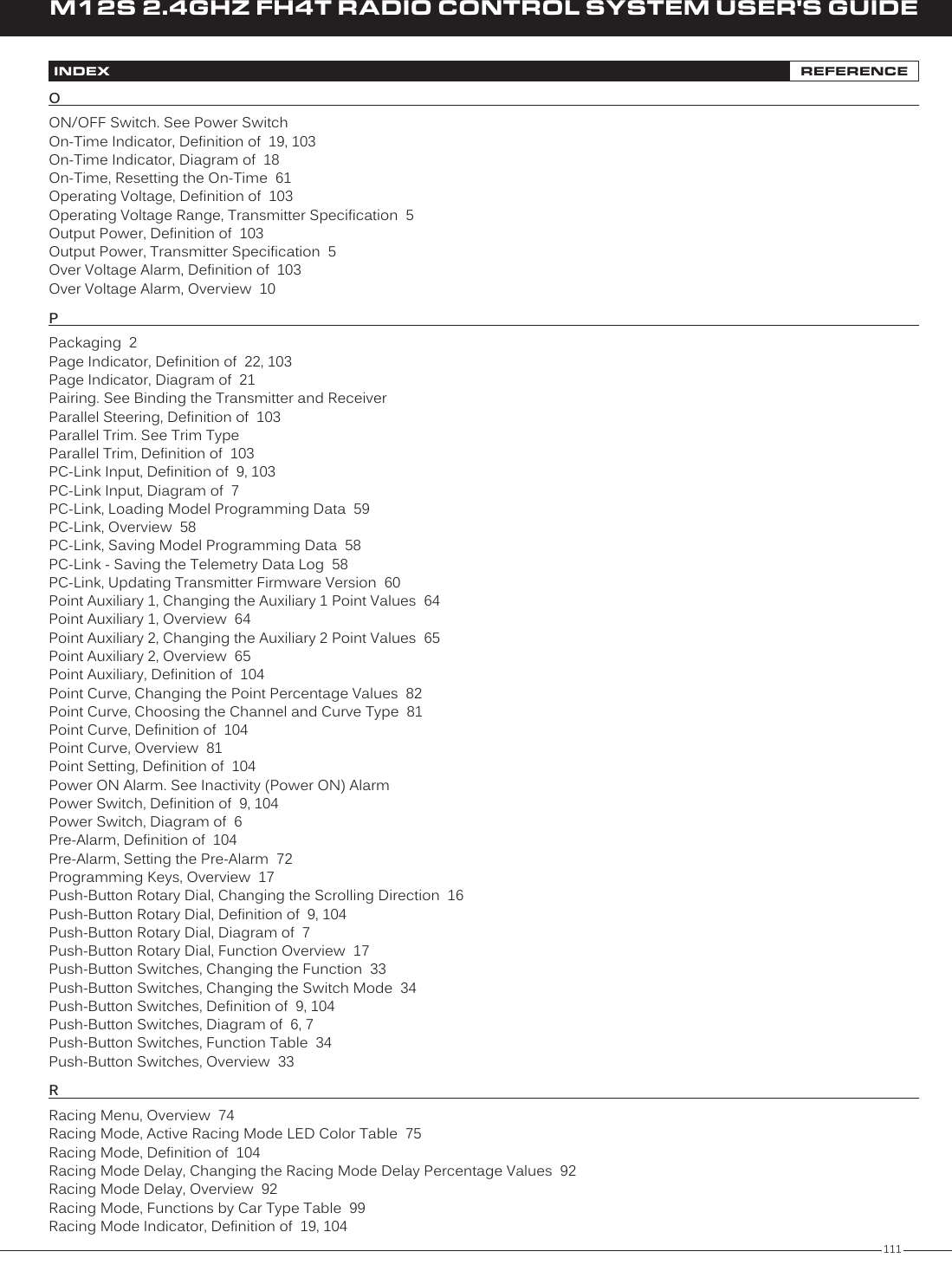
![86M12S 2.4GHZ FH4T RADIO CONTROL SYSTEM USER'S GUIDEWhen the Throttle Offset function is turned ON, [OFFST] ON will be momentarily displayed in a pop-up window, LED1 will flash and an Audible Alarm will sound until the Throttle Offset function is turned OFF.Changing the Position Percentage Value:1) From within the RACING menu, scroll UP or DOWN to highlight the OFFSET menu.2) Press the ENTER key to open the OFFSET menu. OFFSET > OFF will be highlighted.3) Scroll UP or DOWN to highlight POSITION > 0%.4) Press the ENTER key, then scroll UP or DOWN to choose the desired High Side (H) or Brake Side (B) Position percentage value. The Position percentage value determines the position the Throttle servo Neutral Point will shift to when the Throttle Offset function is turned ON.Turning the Throttle Offset Function ON and OFF:1) From within the OFFSET menu, scroll UP or DOWN to highlight OFFSET > OFF.2) Press the ENTER key, then scroll UP or DOWN to choose the desired Offset value, either ON or OFF.OFFSET setting range is ON and OFF. The default setting is OFF.Remember, the Throttle Offset function can be turned ON and OFF using Push-Button Switch Sw1 without needing to access the OFFSET menu.POSITION setting range is H100% to B100%. The default setting is 0%.Changing the Brake Lock Percentage Value:When Car Type II, III, IV,VI or VII is Selected, the Brake Lock function can be programmed to apply Brake to keep your Model from moving while the Throttle Offset Position is increased. If your Car Type features two separate Brake channels, such as Car Type IV, the Brake Lock function percentage value will affect both Brake channels equally.1) From within the OFFSET menu, scroll UP or DOWN to highlight BR-LOCK > OFF.2) Press the ENTER key, then scroll UP or DOWN to choose the desired Brake Lock percentage value. The Brake Lock percentage value determines the position your separate Brake servo (or servos) will shift to when the Throttle Offset function is turned ON.BR-LOCK setting range is OFF and 0% to 100%. The default setting is OFF.OFFSET MENU {THROTTLE OFFSET}RACINGThrottle Offset Programming Values can be changed while you're driving by Assigning these functions to a Trim Switch, the Auxiliary Dial or the Auxiliary Lever. For more information, see the ASSIGN Menu section on pages 33 ~ 38.In the default configuration, Push-Button Switch Sw1 turns the Throttle Offset function ON and OFF.](https://usermanual.wiki/Sanwa-Electronic-Instrument-Co/90486.User-Manual-5/User-Guide-2587751-Page-14.png)
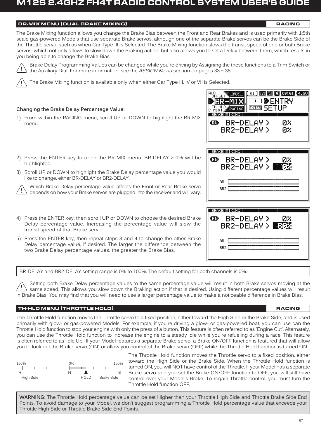
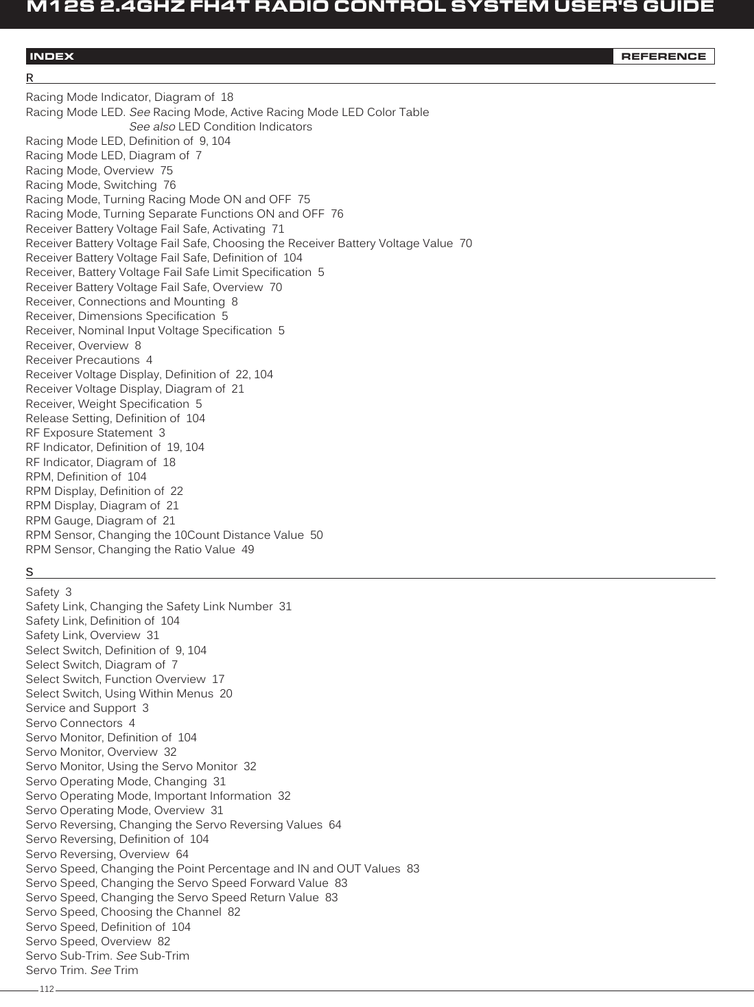
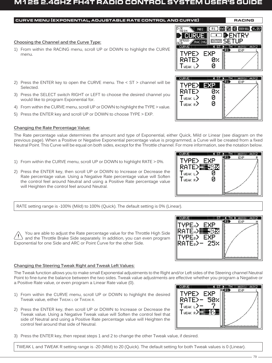
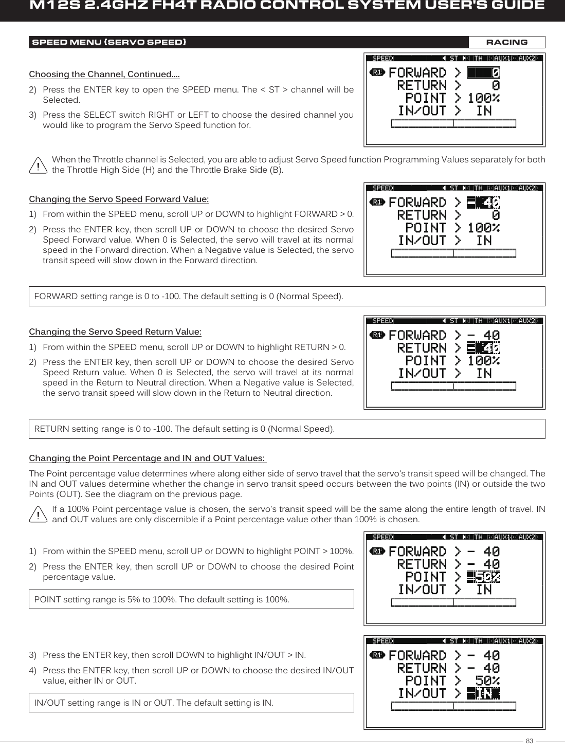
![88M12S 2.4GHZ FH4T RADIO CONTROL SYSTEM USER'S GUIDETH-HLD MENU {THROTTLE HOLD}RACINGSo that the Throttle Hold function can be turned ON and OFF while you're driving, it must first be Assigned to a Push-Button Switch. For more information, see the Push-Button Switch Assignments section on pages 33 ~ 34. When turned ON and OFF, [TH-HOLD] ACT or [TH-HOLD] INH will be displayed momentarily in a pop-up window.The Throttle Hold percentage value can be changed while you're driving by Assigning the Hold function to a Trim Switch or the Auxiliary Dial. For more information, see the ASSIGN Menu section on pages 33 ~ 38.Changing the Hold Percentage Value:1) From within the RACING menu, scroll UP or DOWN to highlight the TH-HLD menu.2) Press the ENTER key to open the TH-HLD menu. HOLD > 0% will be highlighted.3) Press the ENTER key, then scroll UP or DOWN to choose the desired Hold percentage value. The Hold percentage value determines the position the Throttle servo will move to when the Throttle Hold function is turned ON. Choosing a Positive Hold percentage value will move the Throttle servo toward the High Side and choosing a Negative Hold percentage value will move the Throttle Servo toward the Brake Side.HOLD setting range is 150% to -150%. The default setting is 0%.Turning the Throttle Hold Function ON and OFF:1) From within the TH-HLD menu, scroll UP or DOWN to highlight ACT/INH > INH.2) Press the ENTER key, then scroll UP or DOWN to choose the desired ACT/INH setting, either ACT (Active ON) or INH (Inhibited OFF).ACT/INH setting range is ACT and INH. The default setting is INH.We suggest Assigning the Throttle Hold function to a Push-Button Switch so that you can turn it ON and OFF without needing to access the TH-HLD menu. See the notation at the top of the page. In addition, ON and OFF behavior will differ based on the ACT/INH setting you choose. We recommend using the INH setting. With this setting, the Throttle Hold function will always be OFF until you turn it ON. If you choose ACT, the Throttle Hold function will always be ON until you turn it OFF.Changing the Brake Lock-Out Value:When Car Type II, III, IV,VI or VII is Selected, the Brake Lock-Out function can be programmed, which gives you the option to lock out the Brake servo(s) or retain control of the Brake servo(s). This gives you the option of controlling your separate Brake servo(s) to keep your Model from moving, even when your engine's idle Increases when the Throttle Hold function is turned ON. If your Car Type features two separate Brake channels, such as Car Type IV, the Brake Lock-Out function will affect both Brake channels equally.1) From within the TH-HLD menu, scroll UP or DOWN to highlight BR > ON.2) Press the ENTER key, then scroll UP or DOWN to choose the desired Brake value, either ON or OFF. When set to ON, your separate Brake servo(s) will be locked out along with the Throttle servo when the Throttle Hold function is turned ON. When set to OFF, you will retain control of your separate Brake servo(s) when the Throttle Hold function is turned ON.BR setting range is ON and OFF. The default setting is ON.Keep in mind that the Throttle Hold percentage value can be set Higher than your Throttle High Side and Throttle Brake Side End Points. To avoid damage to your Model, we don't suggest programming a Throttle Hold percentage value that exceeds your Throttle High Side or Throttle Brake Side End Points.](https://usermanual.wiki/Sanwa-Electronic-Instrument-Co/90486.User-Manual-5/User-Guide-2587751-Page-16.png)