Sanwa Electronic Instrument Co 90486 2.4GHz Radio Control System User Manual 2
Sanwa Electronic Instrument Co Ltd 2.4GHz Radio Control System 2
Contents
- 1. User Manual-1
- 2. User Manual-2
- 3. User Manual-3
- 4. User Manual-4
- 5. User Manual-5
User Manual-2
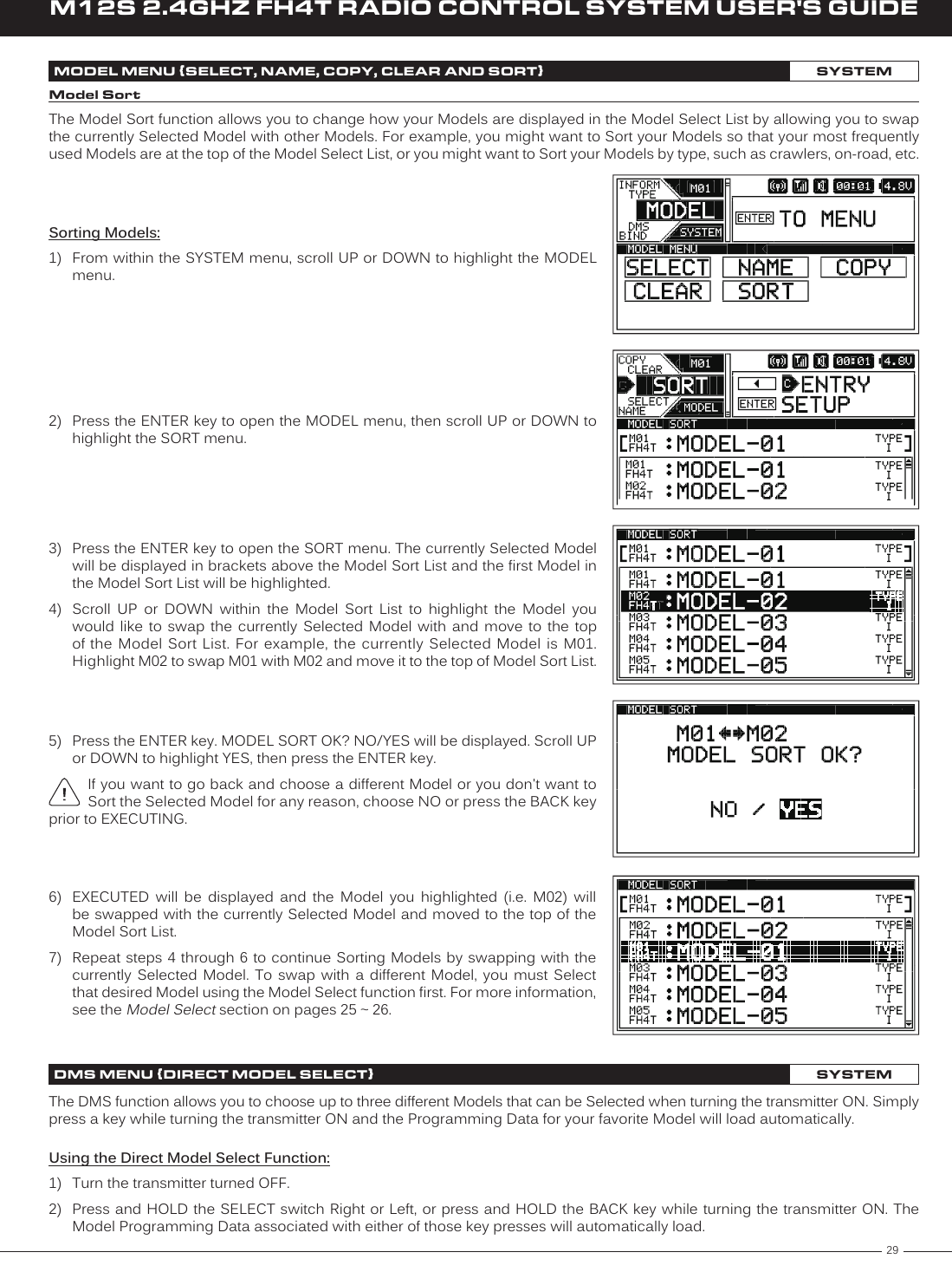
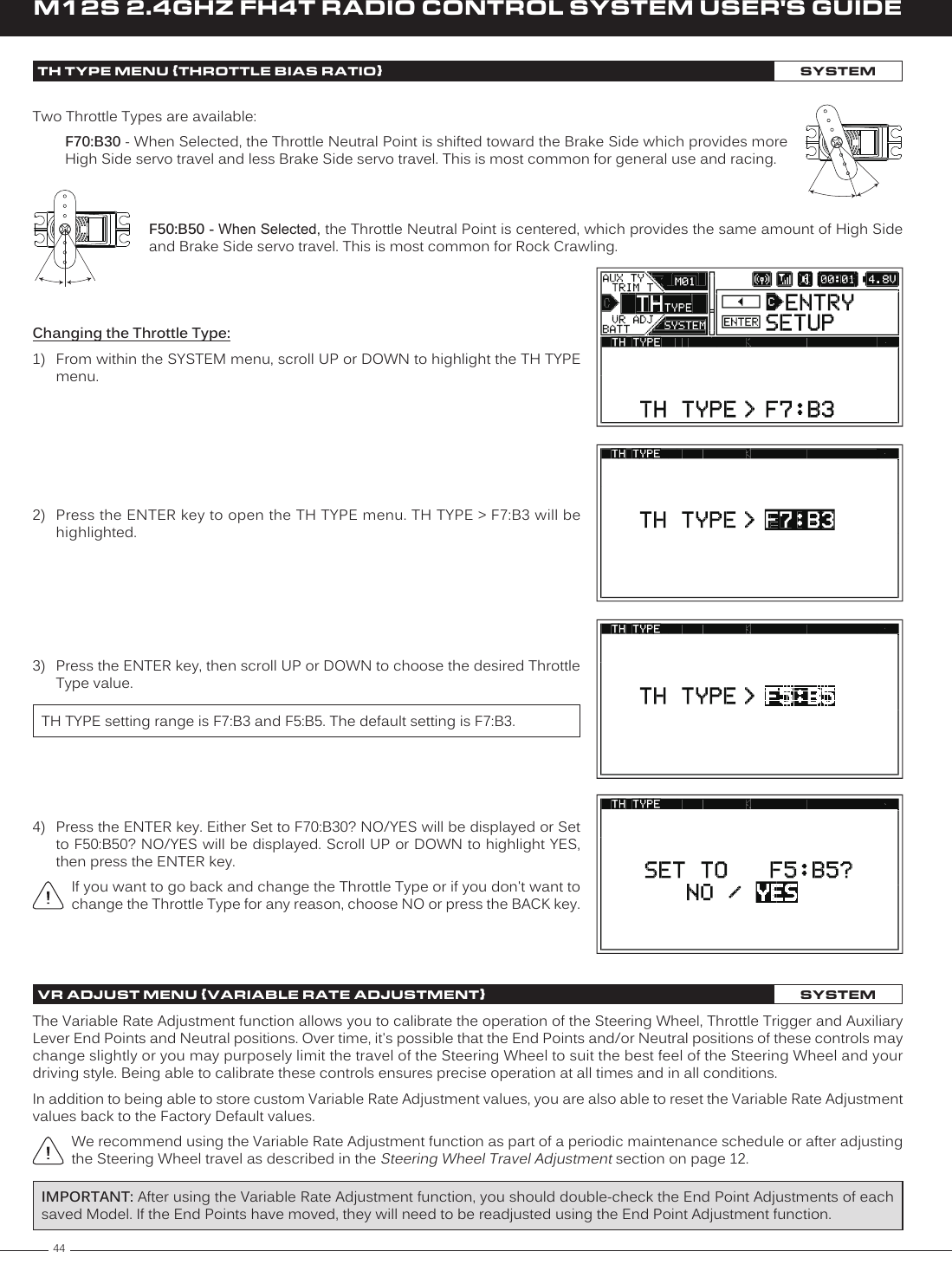
![33M12S 2.4GHZ FH4T RADIO CONTROL SYSTEM USER'S GUIDETRThe ASSIGN menu allows you to Assign different functions to each of the three Push-Button Switches, the five Trim Switches, the Auxiliary Dial and the Auxiliary Lever. Each of the three Push-Button Switches can have up to two functions Assigned to it and the ON/OFF behavior can be changed. In addition, the Direction of Travel and the Trim Resolution of the five Trim Switches and the Auxiliary Dial can be changed.ASSIGN MENU {SWITCH, DIAL AND LEVER FUNCTION ASSIGNMENTS}SYSTEMAuxiliary LeverSwitch Sw3Switch Trm5Switch Sw1Auxiliary DialSwitch Trm3Switch Trm1Switch Trm2Switch Trm4Switch Sw2Push-Button Switch Function AssignmentsThe Switch Assignments function allows you to Assign various functions to the three Push-Button Switches Sw1, Sw2 and Sw3. This allows you to use the Push-Button Switches to turn functions ON and OFF while you're driving. Up to two different functions can be Assigned to each switch and the ON and OFF behavior of each switch can be changed to either PUSH or TOGGLE to suit the programmed function and your specific requirements.Push-Button Switch functions vary based on the Car Type Selected in the TYPE menu. For more information, see the table on the next page.Changing the Push-Button Switch Function Assignments:1) From within the SYSTEM menu, scroll UP or DOWN to highlight the ASSIGN menu.2) Press the ENTER key to open the ASSIGN menu. The SWITCH menu will be highlighted.3) Press the ENTER key to open the SWITCH menu. SW1 [FUNCTION 1] > OFFSET will be highlighted. 4) Scroll UP or DOWN to highlight the Switch Number and Function you would like to change. Choose from SW1 [FUNCTION 1 or 2], SW2 [FUNCTION 1 or 2] or SW3 [FUNCTION 1 or 2].](https://usermanual.wiki/Sanwa-Electronic-Instrument-Co/90486.User-Manual-2/User-Guide-2587748-Page-10.png)
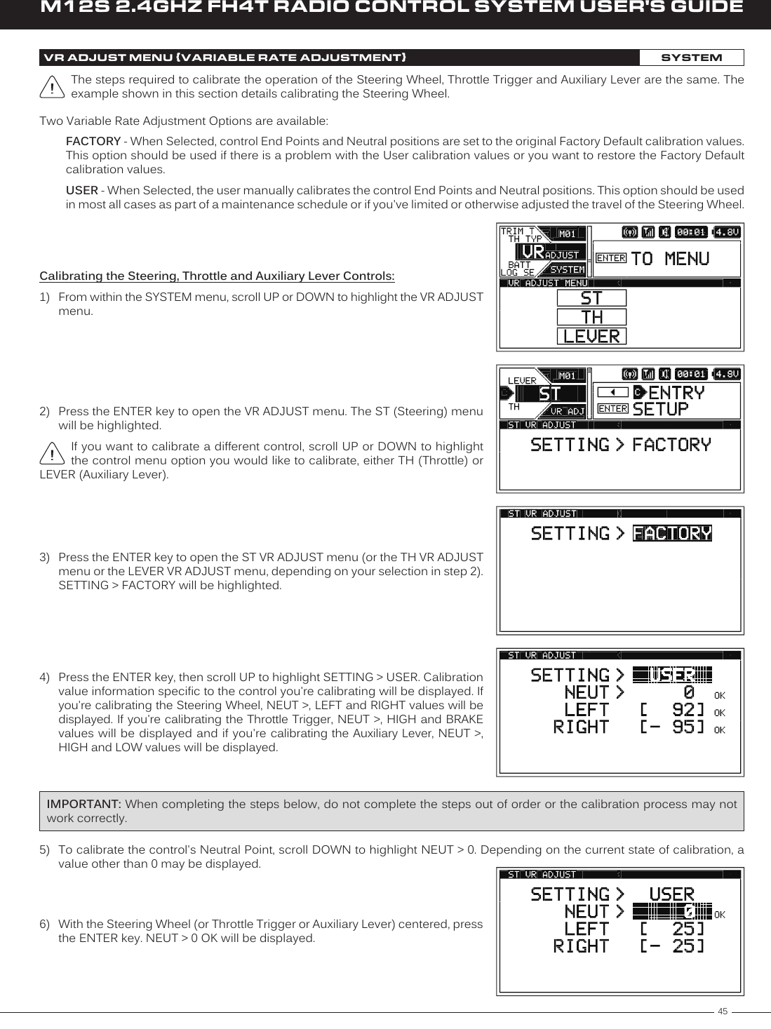
![34M12S 2.4GHZ FH4T RADIO CONTROL SYSTEM USER'S GUIDESw2*Sw1*Sw3*Sw3*ASSIGN MENU {SWITCH, DIAL AND LEVER FUNCTION ASSIGNMENTS}SYSTEMChanging the Push-Button Switch Function Assignments, Continued....5) Press the ENTER key, then scroll UP or DOWN to choose the desired function for the Switch and Function Number you highlighted. A list of functions that can be Assigned to the Push-Button Switches are shown in the table below.6) Press the ENTER key, then repeat steps 4 and 5 to any other desired Push-Button Switch Function Assignments. Although two different functions can be Assigned to the same Push-Button Switch, those functions cannot be controlled independently. AUX may control different functions depending on the Car Type.TYP I---ALBOFFSETAUX1AUX2LAPINT1INT2TH-HOLDTYP II TYP III TYP IV TYP V TYP VI TYP VII TYP VIII TYP IX TYP X---ALBOFFSETAUXLAPINT1INT2TH-HOLD---ALBOFFSETAUXLAPINT1INT2TH-HOLD---ALBOFFSETLAPINT1INT2TH-HOLD---ALBOFFSETAUXLAPINT1INT2TH-HOLD---ALBOFFSETLAPINT1INT2TH-HOLD---ALBOFFSETLAPINT1INT2TH-HOLD---ALBOFFSETAUXLAPINT1INT2---ALBOFFSETAUXLAPINT1INT2---ALBOFFSETLAPINT1INT2SWTYPEChanging the Switch Mode:The ON and OFF behavior of each Push-Button Switch can be changed to suit the programmed function and your specific requirements. The following Switch Modes are available:TOGGLE - When Selected, press the Push-Button Switch to turn the function ON and press the Push-Button Switch a second time to turn the function OFF. PUSH - When Selected, press and HOLD the Push-Button Switch to turn the function ON. Release the Push-Button Switch to turn the function OFF.1) From within the SWITCH menu, scroll UP or DOWN to highlight the Switch Number [MODE] you would like to change. Choose from SW1 [MODE], SW2 [MODE] or SW3 [MODE].Trim Switch Function AssignmentsThe Trim Assignments function allows you to Assign a multitude of different functions to the five Trim Switches Trm1, Trm2, Trm3, Trm4 and Trm5. This allows you to use the Trim Switches to control those functions while you're driving. In addition, the Trim Resolution (Step value) and the Direction of Travel (REV) of each Trim Switch can be changed.For a complete list of functions that can be Assigned to the Trim Switches, see the Trim Switch Auxiliary Dial and Auxiliary Lever Functions tables on page 100.*Indicates default function for Selected Car Type.2) Press the ENTER key, then scroll UP or DOWN to change the desired Switch Mode value. Choose from either TOGGLE or PUSH.MODE setting range is PUSH and TOGGLE. The default setting for SW1 is TOGGLE and for SW2 and SW3 is PUSH.3) Repeat step 2 to change any other desired Switch Mode values.](https://usermanual.wiki/Sanwa-Electronic-Instrument-Co/90486.User-Manual-2/User-Guide-2587748-Page-11.png)
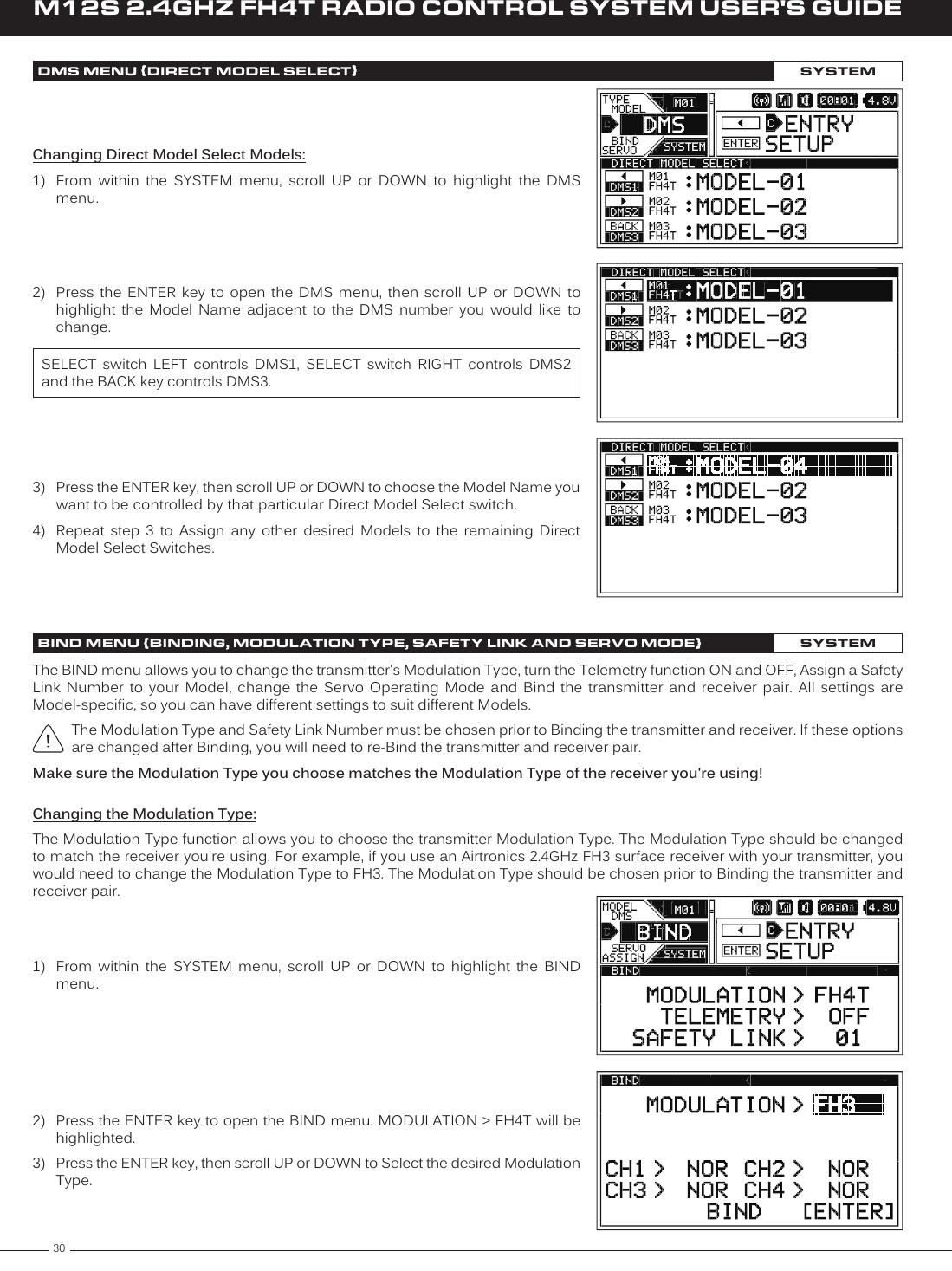
![35M12S 2.4GHZ FH4T RADIO CONTROL SYSTEM USER'S GUIDETRChanging the Trim Switch Function Assignments:1) From within the SYSTEM menu, scroll UP or DOWN to highlight the ASSIGN menu.ASSIGN MENU {SWITCH, DIAL AND LEVER FUNCTION ASSIGNMENTS}SYSTEM2) Press the ENTER key to open the ASSIGN menu, then scroll UP or DOWN to highlight the TRIM menu.3) Press the ENTER key to open the TRIM menu. TRM1 [FUNCTION] > TRIMST will be highlighted.4) Scroll UP or DOWN to highlight the Trim Switch Number you would like to change. Choose from TRM1, TRM2, TRM3, TRM4 or TRM5. 5) Press the ENTER key, then scroll UP or DOWN to choose the desired function for the Trim Switch Number you highlighted. A complete list of functions that can be Assigned to the Trim Switches are shown in the tables on page 100.6) Press the ENTER key, then repeat steps 4 and 5 to any other desired Trim Switch Function Assignments. Changing the Trim Switch Step Value:The Step function allows you to adjust how far a servo travels or a function moves when a Trim Switch is pressed. You can Increase the Trim Resolution by Decreasing the Step value, so that the amount of travel is less when you press the Trim Switches. This makes it possible to fine-tune travel extremely accurately. Alternately, you could Decrease the Trim Resolution by Increasing the Step value, so that the amount of travel is more when you press the Trim Switches. This may not be as accurate, but it allows you to command large amounts of travel or function movement at a time. 1) From within the TRIM menu, scroll UP or DOWN to highlight the Trim Switch Number [STEP] you would like to change. Choose from TRM1 [STEP], TRM2 [STEP], TRM3 [STEP], TRM4 [STEP] or TRM5 [STEP].2) Press the ENTER key, then scroll UP or DOWN to change the desired Trim Switch Step value.STEP setting range is 0 to 100. The default setting is 1 or 5 depending on the Trim Switch Number. The Step value is a percentage of travel.3) Repeat step 2 to change any other desired Trim Step values.](https://usermanual.wiki/Sanwa-Electronic-Instrument-Co/90486.User-Manual-2/User-Guide-2587748-Page-12.png)
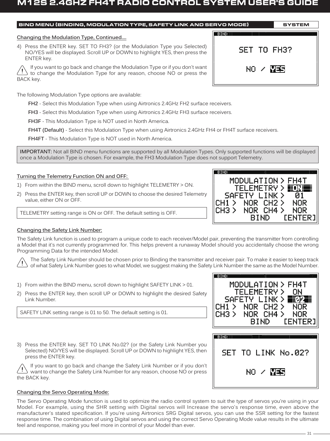
![36M12S 2.4GHZ FH4T RADIO CONTROL SYSTEM USER'S GUIDEASSIGN MENU {SWITCH, DIAL AND LEVER FUNCTION ASSIGNMENTS}SYSTEMChanging the Trim Switch Direction of Travel:The direction that the Trim Switches move the servos or function values can be changed from Normal to Reverse. In Normal mode, the Trim Switches will move the servos toward the High Side or Increase function values when the Trim Switches are pushed Forward. In Reverse mode, the Trim Switches will move the servos toward the Low Side or Decrease function values when the Trim Switches are pushed Forward. 1) From within the TRIM menu, scroll UP or DOWN to highlight the Trim Switch Number [REV] you would like to change. Choose from TRM1 [REV], TRM2 [REV], TRM3 [REV], TRM4 [REV] or TRM5 [REV].Auxiliary Dial Function AssignmentsThe Dial Assignments function allows you to Assign a multitude of different functions to the Auxiliary Dial. This allows you to use the Auxiliary Dial to control those functions while you're driving. The Auxiliary Dial can control either of the two Auxiliary channels or it can control a function, such as Steering Dual Rate or Steering Exponential. In addition, the Trim Resolution (Step value) and the Direction of Travel (REV) of the Auxiliary Dial can be changed.Changing the Auxiliary Dial Function Assignment:1) From within the SYSTEM menu, scroll UP or DOWN to highlight the ASSIGN menu.2) Press the ENTER key to open the ASSIGN menu, then scroll UP or DOWN to highlight the DIAL menu.3) Press the ENTER key to open the DIAL menu. DIAL [FUNCTION] > AUX1 will be highlighted.4) Press the ENTER key, then scroll UP or DOWN to choose the desired function you want to Assign to the Auxiliary Dial. A complete list of functions that can be Assigned to the Auxiliary Dial is shown in the table on page 100.Changing the Auxiliary Dial Step Value:The Step function allows you to adjust how far a servo travels or a function moves when the Auxiliary Dial is turned. You can Increase the Trim Resolution by Decreasing the Step value, so that the amount of travel is less when you turn the Auxiliary Dial. This makes it possible to fine-tune servo travel or function movement extremely accurately. Alternately, you could Decrease the Trim Resolution by Increasing the Step value, so that the amount of travel is more when you turn the Auxiliary Dial. This may not be as accurate, but it allows you to command large amounts of servo travel or function movement at a time. 2) Press the ENTER key, then scroll UP or DOWN to change the desired Trim Switch Reverse value.REV setting range is NOR and REV. The default setting is NOR.3) Repeat step 2 to change any other desired Trim Switch Reverse values.](https://usermanual.wiki/Sanwa-Electronic-Instrument-Co/90486.User-Manual-2/User-Guide-2587748-Page-13.png)
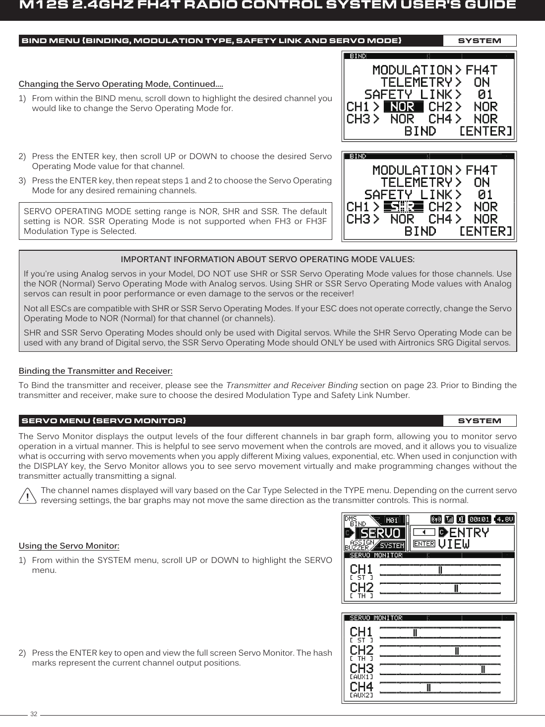
![37M12S 2.4GHZ FH4T RADIO CONTROL SYSTEM USER'S GUIDETRASSIGN MENU {SWITCH, DIAL AND LEVER FUNCTION ASSIGNMENTS}SYSTEMChanging the Auxiliary Dial Step Value, Continued: 1) From within the DIAL menu, scroll UP or DOWN to highlight DIAL [STEP] > 5.2) Press the ENTER key, then scroll UP or DOWN to choose the desired Auxiliary Dial Step value.STEP setting range is 1 to 100. The default setting is 5. The Step value is a percentage of travel.Changing the Auxiliary Dial Direction of Travel:The direction that the Auxiliary Dial moves the servo or function value can be changed from Normal to Reverse. In Normal mode, the Auxiliary Dial will move the servo toward the High Side or Increase a function value when the Auxiliary Dial is turned clockwise. In Reverse mode, the Auxiliary Dial will move the servo toward the Low Side or Decrease a function value when the Auxiliary Dial is turned counter-clockwise.1) From within the DIAL menu, scroll UP or DOWN to highlight DIAL [REV] > NOR.2) Press the ENTER key, then scroll UP or DOWN to choose the desired Auxiliary Dial Reverse value.REV setting range is NOR and REV. The default setting is NOR.Auxiliary Lever Function AssignmentsThe Lever Assignments function allows you to Assign various functions to the Auxiliary Lever. This allows you to use the Auxiliary Lever to control those functions while you're driving. The Auxiliary Lever can control either of the two Auxiliary channels or it can control a function, such as Steering Dual Rate or Steering Exponential.Changing the High and Low Tweak values determines the amount of travel and direction. Changing the Auxiliary Lever Function Assignment:1) From within the SYSTEM menu, scroll UP or DOWN to highlight the ASSIGN menu.2) Press the ENTER key to open the ASSIGN menu, then scroll UP or DOWN to highlight the LEVER menu.3) Press the ENTER key to open the LEVER menu. LEVER [FUNCTION] > AUX2 will be highlighted.4) Press the ENTER key, then scroll UP or DOWN to choose the desired function you want to Assign to the Auxiliary Lever. A complete list of functions that can be Assigned to the Auxiliary Lever are shown in the tables on page 100.](https://usermanual.wiki/Sanwa-Electronic-Instrument-Co/90486.User-Manual-2/User-Guide-2587748-Page-14.png)
![38M12S 2.4GHZ FH4T RADIO CONTROL SYSTEM USER'S GUIDECLICKTRIMCENTERMULTITIMER SWINT1 TIMERINT2 TIMERLAP-PRELAP GOALOFFSETTELEMETRYLIMITASSIGN MENU {SWITCH, DIAL AND LEVER FUNCTION ASSIGNMENTS}SYSTEMChanging the Auxiliary Lever High and Low Tweak Values:The High and Low Tweak values both determine how far and in which direction the Auxiliary Lever controls the function Assigned to it when the Auxiliary Lever is moved Up and Down, regardless if the Auxiliary Lever is controlling a servo, such as Auxiliary Channel 2 or a function parameter, such as Steering Trim. For example, if you Assign AUX2 to the Auxiliary Lever and adjust the Tweak values to +50 and -50, the Auxiliary 2 servo will be centered when the Auxiliary Lever is centered and will travel 50% in one direction when the Auxiliary Lever is moved Up and travel 50% in the other direction when the Auxiliary Lever is moved Down. Alternately, if you Assign TRIMST to the Auxiliary Lever and adjust the Tweak values to +50 and -50, the Auxiliary Lever will control Steering Trim from 0% to 50%. 1) From within the LEVER menu, scroll UP or DOWN to highlight LEVER [TWEAK (H)] > +100.2) Press the ENTER key, then scroll UP or DOWN to choose the desired High Side Tweak value. Increasing the Tweak value will Increase travel in the High Side direction and Decreasing the Tweak value will Decrease travel in the High Side direction. Using a Negative value will change the direction of travel.TWEAK (H) setting range is -100 to +100. The default setting is +100.3) Scroll DOWN to highlight LEVER [TWEAK (L)] > -100.4) Press the ENTER key, then scroll UP or DOWN to choose the desired Low Side Tweak value. Decreasing the Tweak value will Increase travel in the Low Side direction and Increasing the Tweak value will Decrease travel in the Low Side direction. Using a Positive value will change the direction of travel.TWEAK (L) setting range is -100 to +100. The default setting is -100.BUZZER MENU {AUDIBLE KEY TONES AND ALARMS}SYSTEMThe Buzzer function allows you to change the Tone and Volume of many of the audible sounds that the transmitter makes. This ranges from sounds that are made when you press Trim and Push-Button Switches, scroll UP or DOWN or press the ENTER key, Lap and Interval Timer alarms, Telemetry alarms, transmitter Voltage Limit alarm and more.The Volume can be Increased or Decreased (or Muted) and the Tones can be changed to suit your preference. In addition, many of the Tones can be set separately for the first half and the second half of a Tone, making it easier to differentiate between the two halves.DESCRIPTIONControls Key Press Tones, Such as ENTER, BACK, SELECT and All Push-Button SwitchesControls All Trim Switch Key Press TonesControls the Trim Switch, Auxiliary Dial and Auxiliary Lever Neutral Point Indicator TonesControls the Push-Button Rotary Dial scroll UP and Scroll DOWN Tones*Controls the Lap Timer Start and Stop Tones*Controls the First Interval Timer Start and Stop TonesControls the Second Interval Timer Start and Stop TonesControls the Lap Timer Pre-Alarm ToneControls the Lap Timer Goal Alarm ToneControls the Offset Function Alarm ToneControls the Various Telemetry System Alarms*Controls the Transmitter Limit Voltage Alarm***Only TONE1 (first half) changes affected. No affect on TONE2 (second half) changes.FUNCTIONThe following is a list of the functions that the Tone and Volume can be adjusted for:](https://usermanual.wiki/Sanwa-Electronic-Instrument-Co/90486.User-Manual-2/User-Guide-2587748-Page-15.png)
![39M12S 2.4GHZ FH4T RADIO CONTROL SYSTEM USER'S GUIDETRChanging the Audible Tones:1) From within the SYSTEM menu, scroll UP or DOWN to highlight the BUZZER menu.2) Press the ENTER key to open the BUZZER menu. CLICK [TONE1] > 1 will be highlighted.3) Scroll UP or DOWN to highlight the Function Tone Number you would like to change.4) Press the ENTER key, then scroll UP or DOWN to choose the desired Tone value for either [TONE1] and/or [TONE2]. Increasing the Tone value will Increase the Tone of the Selected function and Decreasing the Tone value will Decrease the Tone of the Selected function.BUZZER MENU {AUDIBLE KEY TONES AND ALARMS}SYSTEMTONE1 and TONE2 setting range is 1 to 7. The default setting is 1. TONE1 changes the first half Tone and TONE2 changes the second half Tone.Changing the Volume:1) From within the BUZZER menu, Scroll UP or DOWN to highlight the Function Volume Number you would like to change.2) Press the ENTER key, then scroll UP or DOWN to choose the desired Volume value. Increasing the Volume value will Increase the Volume of the Selected function and Decreasing the Volume value will Decrease the Volume of the Selected function. Choosing OFF will Mute the Selected function.VOLUME setting range is OFF to 5. The default setting is 4.VIBRATOR MENU {VIBRATION ALERTS AND ALARMS}SYSTEMThe Vibrator function makes the transmitter vibrate like a cell phone to make you aware of different alerts and alarms that you might encounter during use. For example, you can program the transmitter to vibrate when the an Interval Timer starts or stops or when you reach a Lap Timer Goal Time. You can also program the transmitter to vibrate when the transmitter reaches the programmed Voltage Alert value or when the transmitter is turned ON and more. The Vibrate function is particularly useful if you've Muted any of these related audible alerts and alarms. The Vibrate function can also be used along with these related audible alerts and alarms to provide a level of tactile feedback while you're driving.3) Press the ENTER key, then repeat steps 1 and 2 to change the Volume value for any other desired functions.5) Press the ENTER key, then repeat steps 3 and 4 to change the Audible Tones for any other desired functions.](https://usermanual.wiki/Sanwa-Electronic-Instrument-Co/90486.User-Manual-2/User-Guide-2587748-Page-16.png)