Schlage Electronic Security VIPFP Door Lock User Manual 57032 A
Schlage Electronic Security Door Lock 57032 A
Contents
- 1. Manual 5100
- 2. Manual 5500
- 3. Manual 993
Manual 5100
Form 57032 Rev. A 01-05-2004
VIP 5100 OPEN ARCHITECTURE CYLINDRICAL LOCK
INSTALLATION MANUAL
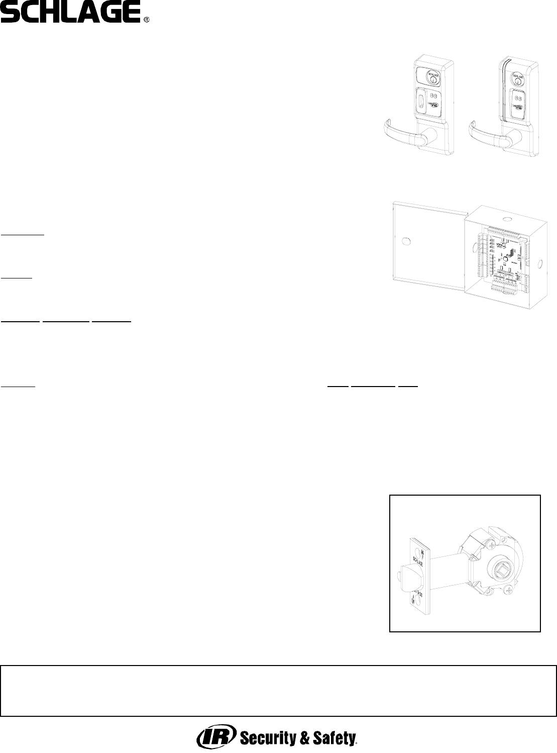
5100 CYLINDRICAL
LOCKSET - STANDARD
The VIP 5100 series lock is a microprocessor controlled, electromechanical locking system.
It is an open architecture product designed to interface with 3rd party panels ecompassing
all the features of the lock, reader, door status* and egress (rex/request to exit) indication in
one fire-rated piece of hardware. The 5100 employs a heavy-duty mechanical design tested
and complying with ANSI/BHMA grade 1 standards for performance and reliability. It is pow-
ered by 12 or 24 volts DC with only four wires required - two for power and two for commu-
nications. The lock communicates with a PIB (panel interface board) which communicates
with the panel as if it were separate components of an access control system.
Operationally, the outside lever is normally locked and the inside lever always retracts the
bolt to allow egress. Electronic access control is achieved by entering an”Access Credential”
(magnetic stripe card or Prox fob or card). The panel controls the lock through the PIB.
*Cylindrical model requires separate door status switch (included) to be installed in the door
and frame and connected to the VIP lock.
Please refer to all instruction manuals involved in the installation before you begin.
Functions:
VIP 5196-FSA: Cylindrical, Fail Safe (unlocked)
VIP 5196-FSE: Cylindrical, Fail Secure (locked)
Models:
MG: Magnetic stripe card reader
PX: HID Prox card reader
Standard Monitoring Switches:
DSM: Provides door status via data link to panel interface
KSM: Provides mechanical key use events via data link to panel interface
REX: Provides indication of inside lever use for request to exit input via data link
to panel interface
Options:
T3: Track 3 card reader (data must be ABA track 2 format) - MG only
EXT: exterior use option - MG only (PX model has this standard)
KD: Keyed Different, includes Schlage Everest cylinder
KA: Keyed Alike, includes Schlage Everest cylinder
LC: Less Cylinder
SLB: 2-3/4” backset, 1/2” latch bolt
OLB: 2-3/8” backset, 1/2” latch bolt
ELB: 2-3/4” backset, 3/4” latch bolt
BEFORE YOU BEGIN:
Standard units are shipped from the factory to fit 1-3/4” doors. Verify the
door thickness. If the door is not 1-3/4” thick, verify that the door thickness
option was ordered or consult factory.
PRE-INSTALLATION CHECK:
AN OPEN ARCHITECTURE SYSTEM REQUIRES AT LEAST THREE COMPO-
NENTS - A PANEL INTERFACE BOARD (PIB), AN ACCESS CONTROL PANEL
(BY OTHERS) TO WHICH THE PIB IS CONNECTED AND THE VIP LOCK. SEE
DOCUMENTATION FOR THE ACCESS CONTROL PANEL/SOFTWARE THIS
LOCK WILL BE USED WITH FOR ANY PRE-INSTALLATION TESTING REQUIRE-
MENTS AND REMEDIES. REFER TO THE WIRING INFORMATION INCLUDED
WITH THE PIB FOR MORE INFORMATION.
PIB
PX MG
Door Thickness Kits:
Available in 1/8” increments from 1-3/8” to 2-1/2”
This device complies with part 15 of the FCC rules. Operation is subject to the following two conditions: (1) this device may
not cause harmful interference, and (2) this device must accept any interference received, including any interference that may
cause undesired operation. Changes or modifications not expressly approved by the party responsible for compliance could
void the user’s authority to operate the equipment.

Form 57032 Rev. A 01-05-20042
VIP 5100 OPEN ARCHITECTURE CYLINDRICAL LOCK
INSTALLATION MANUAL
WIRE RACEWAY REQUIRED:
It is best to have the wire race way prepared at the door and
frame manufacturer. If this has not been done there are two
suggested preparation methods for making wire paths for the
FSE and FSA models in the field. Select method A or B;
depending on the door and frame circumstances, one may be
better than the other. Consult door manufacturer with any ques-
tions regarding agency listings with respect to fire integrity.
METHOD A:
1. Prep door and frame according to standard template.
2. Determine location of standard 1 inch wire harness through
hole and mark centerline of hole on hinge side of door.
3. Using appropriate drilling jig and drill bits, drill 3/8” or 1/2”
wire race from edge of hinge side into standard wire harness
through hole.
4. Install electric hinge or door cord and run wires.
METHOD B:
1. Prep door and frame according to standard template.
2. Using a 1” drill bit, continue the 1” latch hole through retractor
hole to a depth of 5”. This will allow room for the wiring to pass
around the retractor.
3. Using appropriate drilling jig and drill bits, drill 3/8” or 1/2”
wire race from the latch hole through the door toward the hinge
side. It is not necessary to continue drilling the hole through the
hinge side.
4. Measure up 3 inches from the center of the 2 1/8” retractor
hole and drill a 1 inch through hole on center as shown below.
5. Using a 3/8 inch drill bit, place the tip of the drill into the 1”
wire hole drilled in step 3 and aim at the angles shown. Drill
down and toward the hinge side to intersect the 1” latch hole
(where it was continued in step 2.
4. Install electric hinge or door cord and
run wires.
Note: this method offers the advantage of
not having holes exiting the door edges.
If a door cord is used the door cord wire
hole can be cross drilled into the long
wire race.
WIRE RACE
WIRE RACE
STANDARD WIRE
HARNESS THROUGH
HOLE
METHOD B:
METHOD A:
FSE & FSA HARD WIRED MODELS
REQUIRE WIRING TO BE RUN TO
THE LOCK PREP FROM THE HINGE
SIDE. BELOW IS A SUGGESTED
METHOD TO DO THIS. A DOOR CORD
OR ELECTRIC HINGE OR POWER
TRANSFER DEVICE IS USED TO
ROUTE WIRING FROM FRAME TO
DOOR. NOTE THAT WHEN USING AN
ELECTRIC HINGE IT IS RECOM-
MENDED THAT THE POWER WIRES
BE DOUBLED OR TRIPLED UP (ON
BOTH THE POSITIVE AND GROUND
LEGS) TO AVOID SIGNIFICANT VOLT-
AGE DROP THROUGH THE THIN
WIRES IN THE HINGE.
Form 57032 Rev. A 01-05-20043
VIP 5100 OPEN ARCHITECTURE CYLINDRICAL LOCK
INSTALLATION MANUAL
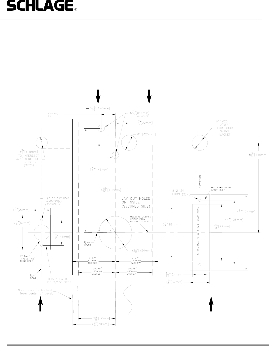
1. PREP DOOR AND FRAME:
A. Determine door hand and correct backset.
B. Mark the horizontal and vertical centerlines for the lockset, latch and strike.
C. Place template on inside of door (opposite the side that the keypad/reader will be on). Line up the correct reference lines
on the template with the edge of the door. The centerline on the door should line up with the vertical centerline of the tem-
plate.
D. Drill holes as described by template.
DOOR EDGE (LATCH) FRAME (STRIKE)
DOOR FACE (LAY OUT ON INSIDE)
Form 57032 Rev. A 01-05-20044
VIP 5100 OPEN ARCHITECTURE CYLINDRICAL LOCK
INSTALLATION MANUAL
2. INSTALL CYLINDER (IF NOT ALREADY DONE), GASKET AND STANDOFFS:
A. Install cam onto cylinder (if not already done.) Cam must be a straight 11/16” design. See below for recommended cams.
B. Insert mortise cylinder into outside escutcheon from front (keypad/reader) side with keyway down.
C. Slide lock washer onto cylinder (tab on top facing out, as shown below.)
D. Using nut tool (provided) tighten nut onto cylinder.
E. Line up nearest notch on nut with tab on lock washer and bend tab using nut tool so nut is secure.
F. Install exterior gasket (if used).
G. Install standoffs.
TEST KEY OPERATION NOW: Turning key clockwise until it stops (about 1/2 turn) should allow the lever to turn retractor.
CYLINDER
RECOMMENDED CAMS:
SCHLAGE EVEREST: P/N B502-948
SCHLAGE CLASSIC: P/N B502-191
NUT TOOL
RETRACTOR ASSEMBLY
LOCK WASHER
NUT
STANDOFFS
EXTERIOR GASKET
TAB
NOTE:
BLOCKING RING REQUIRED FOR CYLINDER
LENGTH GREATER THAN 1-1/8”.
THICKNESS = CYLINDER LENGTH - 1 1/8”
Form 57032 Rev. A 01-05-20045
VIP 5100 OPEN ARCHITECTURE CYLINDRICAL LOCK
INSTALLATION MANUAL
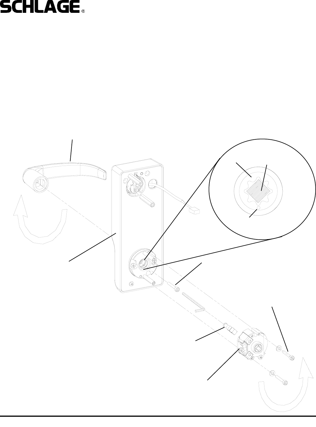
3. CHANGE HAND (IF NECESSARY):
NOTE: The locks are shipped handed as ordered from factory. follow the steps below to reverse the handing:
A. Remove retractor by loosening two 9/64” socket cap screws which attach it to the outside escutcheon.
B. Remove outside spindle.
C. Loosen 5/32” socket cap screw which secures handle to escutcheon.
D. Remove, rotate and re-install handle (NOTE: some handle designs have an adapter.)
E. Re-install outside spindle, making sure that the round end faces the handle, and the spindle is positioned with its edges
vertical and horizontal as shown in detail below. Note that the cam (inside the escutcheon assembly) must be positioned
such that the dot on it faces the 6 O’Clock position (see detail below).
F. Rotate retractor and re-install it.
G. Change the hand of the handle on the inside escutcheon (not shown) the same way. Note that the inside escutcheon has
no retractor.
OUTSIDE ESCUTCHEON
OUTSIDE SPINDLE
(ROUND SIDE TOWARD LEVER)
9/64” SOCKET CAP
SCREW
5/32” SOCKET CAP
SCREW
RETRACTOR
OUTSIDE HANDLE
DOT - FACES
DOWN
OUTSIDE
SPINDLE
POSITION
CAM
DETAIL
Form 57032 Rev. A 01-05-20046
VIP 5100 OPEN ARCHITECTURE CYLINDRICAL LOCK
INSTALLATION MANUAL
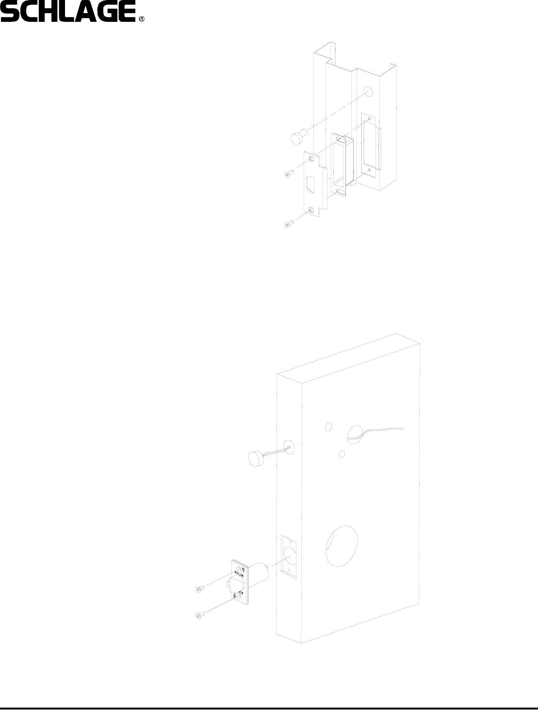
4. INSTALL STRIKE BOX, STRIKE
AND DOOR SWITCH MAGNET:
5. INSTALL LATCH AND DOOR STATUS SWITCH:
A. Install latch into edge of door. Be sure to install it with the beveled edge facing door jamb.
B. Install switch as shown, passing switch wires through to the inside of the door.
01-05-20047
VIP 5100 OPEN ARCHITECTURE CYLINDRICAL LOCK
INSTALLATION MANUAL
Form Form 57032 Rev.
DETAIL
Prongs on latch must
engage with retractor.
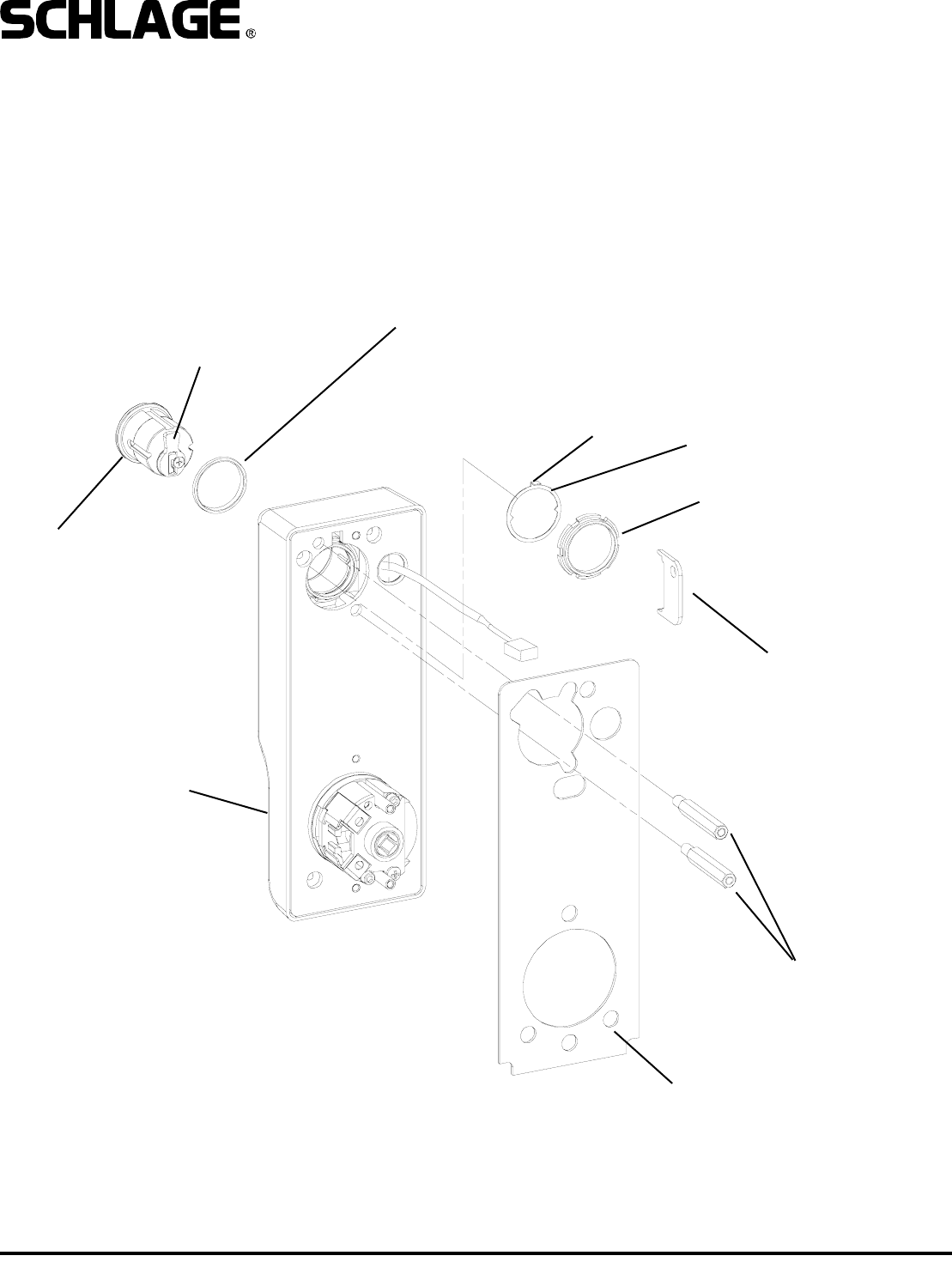
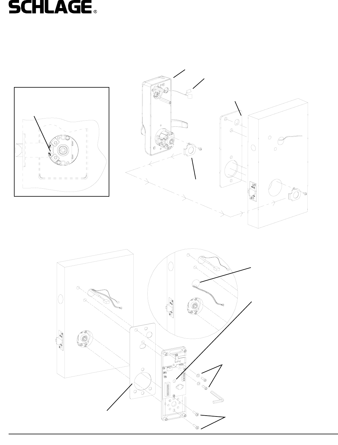
6. INSTALL OUTSIDE ESCUTCHEON ASSEMBLY:
A. Remove latch guard from retractor.
B. If the door is less than 1-3/4” thick, install spacer plate provided.
C. Install outside escutcheon onto door (see detail for latch engagement). Pass wiring harness through wire hole.
D. Re-install latch guard onto retractor.
7. INSTALL INSIDE BASEPLATE ASSEMBLY:
SPACER
(FOR DOORS LESS THAN 1-3/4”)
SPACER
(FOR DOORS LESS THAN 1-3/4”)
SOCKET CAP SCREW,
WASHERS
DATA/POWER WIRES COME
FROM HERE IF WIRING
METHOD “B” WAS USED.
PASS THE WIRES THROUGH
THIS HOLE. (IF A SPACER IS
USED DRILL A HOLE IN THE
SPACER PLATE FOR WIRES TO
PASS THROUGH.)
OUTSIDE ESCUTCHEON
WIRING HARNESS
LATCH GUARD
PHILLIPS HEAD
SCREWS
Form 57032 Rev. A 01-05-20048
VIP 5100 OPEN ARCHITECTURE CYLINDRICAL LOCK
INSTALLATION MANUAL
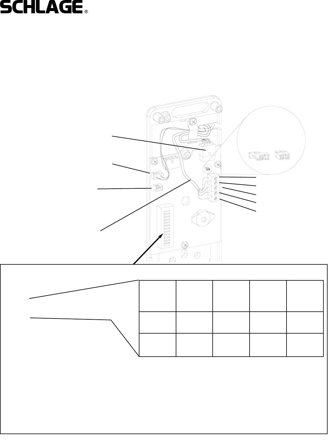
FIELD WIRING FROM
PANEL AND POWER
SUPPLY.
DOOR SWITCH
REX INPUT
(PLUG IN WHEN INSIDE
ESCUTCHEON IS
INSTALLED)
8. MAKE WIRING HARNESS CONNECTIONS :
A. Plug MAIN WIRING HARNESS into PC board.
B. Plug MAKE FIELD CONNECTIONS TO TERMINAL BLOCK.
C. Pug in DOOR STATUS SWITCH as shown.
D. Verify correct lock type setting (FSE/FSA) - see dip switch setting. Note: as ordered from the factory.
E. If lock is the one farthest away from PIB set termination resistor to “on”. All others should be in the “off/parked” position.
F. Test operation of inside lever to make sure that latch retracts fully.
IMPORTANT! See PIB manual for additional connecting instructions.
SHIELD
DATA A
DATA B
GROUND
V+ 1.0A @ 12VDC
0.5A @ 24VDC
OUTSIDE
MAIN HARNESS
CONNECTION OFF
(PARKED)
ON
TERMINATION
RESISTOR:
1: LOCK ADDRESS (SEE CHART)
2: LOCK ADDRESS (SEE CHART)
3: ALWAYS SET TO OFF
4: ALWAYS SET TO OFF
5: OFF = FAIL SECURE (FSE)
ON = FAIL SAFE (FSA)
6: OFF = ALL MG LOCKS
ON = ALL PX LOCKS
7: ALWAYS SET TO OFF
8: ALWAYS SET TO OFF
9: ALWAYS SET TO OFF
10: ALWAYS SET TO OFF
LOCK
ADDRESS
1
LOCK
ADDRESS
2
LOCK
ADDRESS
3
LOCK
ADDRESS
4
DIP SWITCH
1OFF ON OFF ON
DIP SWITCH
2 OFF OFF ON ON
DIP
SWITCH
NUMBER:
Note:
Lock addresses must be used in sequence and cannot
be the same for any two locks connected to a PIB. For
example, if the system has three locks, use addresses
1, 2, and 3 (but not 4). Lock address will correspond to
panel address on the PIB.
Form 57032 Rev. A 9
VIP 5100 OPEN ARCHITECTURE CYLINDRICAL LOCK
INSTALLATION MANUAL
01-05-2004
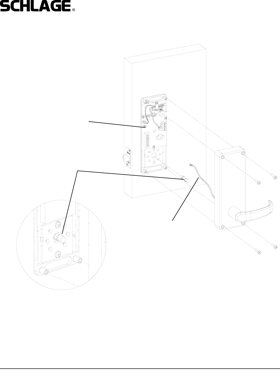
9. INSTALL INSIDE ESCUTCHEON:
Install inside escutcheon assembly onto inside baseplate
using four screws.
IMPORTANT!
1. MAKE SURE THAT INSIDE SPINDLE IS
INSTALLED.
2. PLUG REX SWITCH IN TO BOARD.
3. DO NOT PINCH WIRES BETWEEN PARTS.
10. SEE PIB MANUAL AND SYSTEM/PANEL MANUAL FOR SET UP PROCEDURES.
INSIDE SPINDLE
PLUG REX SWITCH
INTO PC BOARD
DO NOT PINCH WIRES
FOR REX SWITCH
BETWEEN PARTS