ShenZhen Foscam Intelligent Technology FI9900P Outdoor HD IP Camera User Manual Part Three
ShenZhen Foscam Intelligent Technology Co., Ltd. Outdoor HD IP Camera Users Manual Part Three
Contents
- 1. Users Manual Part One
- 2. Users Manual Part Two
- 3. Users Manual Part Three
- 4. User Manual Part Four
Users Manual Part Three
w
ww
ww
w.
.f
fo
os
sc
ca
am
m.
.c
co
om
m
S
Sh
he
en
nz
zh
he
en
n
F
Fo
os
sc
ca
am
m
I
In
nt
te
el
ll
li
ig
ge
en
nt
t
T
Te
ec
ch
hn
no
ol
lo
og
gy
y
C
Co
o.
.,
,
L
Li
im
mi
it
te
ed
d
T
Te
el
l:
:
8
86
6
7
75
55
5
2
26
67
74
4
5
56
66
68
8
F
Fa
ax
x:
:
8
86
6
7
75
55
5
2
26
67
74
4
5
51
16
68
8
49
password), and click “OK” to apply changes.
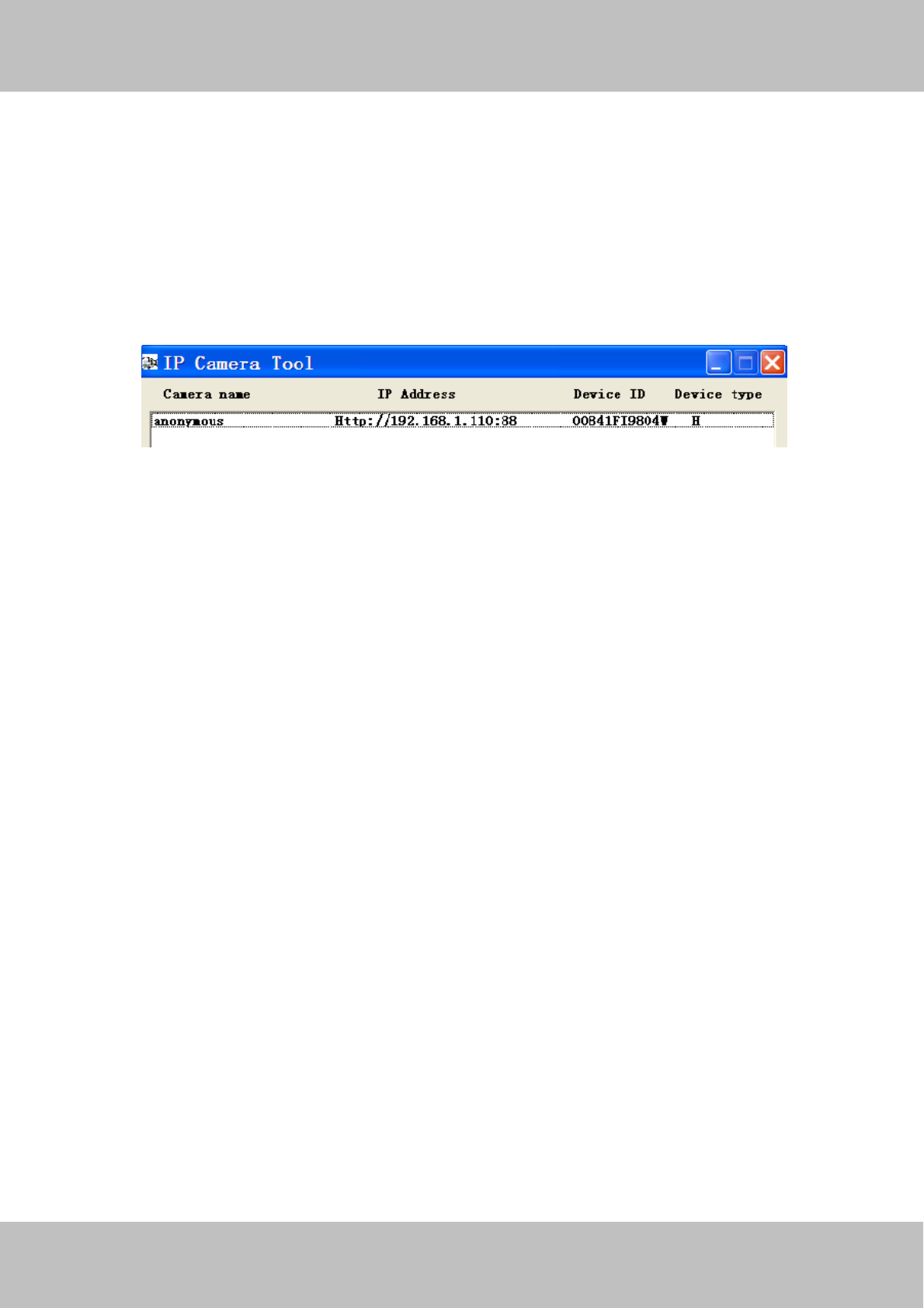
Step 3: Wait around 10 seconds, you’ll see that the camera’s LAN IP address has changed. In our example it
was changed to 2000, so we see http://192.168.8.102:2000 in IP Camera Tool. Also, the LAN IP address is
now fixed at a static IP address of http://192.168.8.102:2000. This IP address will not change even if the
camera is powered off and back on, the camera will remain on this LAN IP address. This is very important that
a static LAN IP address is set, or you may have problems later with remote access and seeing the camera
remotely if the camera loses power and reconnects on a different LAN IP address. Make sure you set a static
LAN IP address!
Figure 4.35
NOTE: If the camera cannot be accessed, please make sure the port forwarding is succeed.
HTTPS port: The default port is 443. You can use the url to access the camera: https:// IP + HTTPS port.
ONVIF port: By default, the ONVIF port is set to 888. Also, they can be assigned with another port number
between 1 and 65535(except 0 and 65534). But make sure they can not be conflict with other existing ports.
RTSP port:The default port is 554,only some IP Cameras have RTSP port.
4.4.7 Mail Settings
If you want the camera to send emails when motion has been detected, here Mail will need to be configured.
w
ww
ww
w.
.f
fo
os
sc
ca
am
m.
.c
co
om
m
S
Sh
he
en
nz
zh
he
en
n
F
Fo
os
sc
ca
am
m
I
In
nt
te
el
ll
li
ig
ge
en
nt
t
T
Te
ec
ch
hn
no
ol
lo
og
gy
y
C
Co
o.
.,
,
L
Li
im
mi
it
te
ed
d
T
Te
el
l:
:
8
86
6
7
75
55
5
2
26
67
74
4
5
56
66
68
8
F
Fa
ax
x:
:
8
86
6
7
75
55
5
2
26
67
74
4
5
51
16
68
8
50
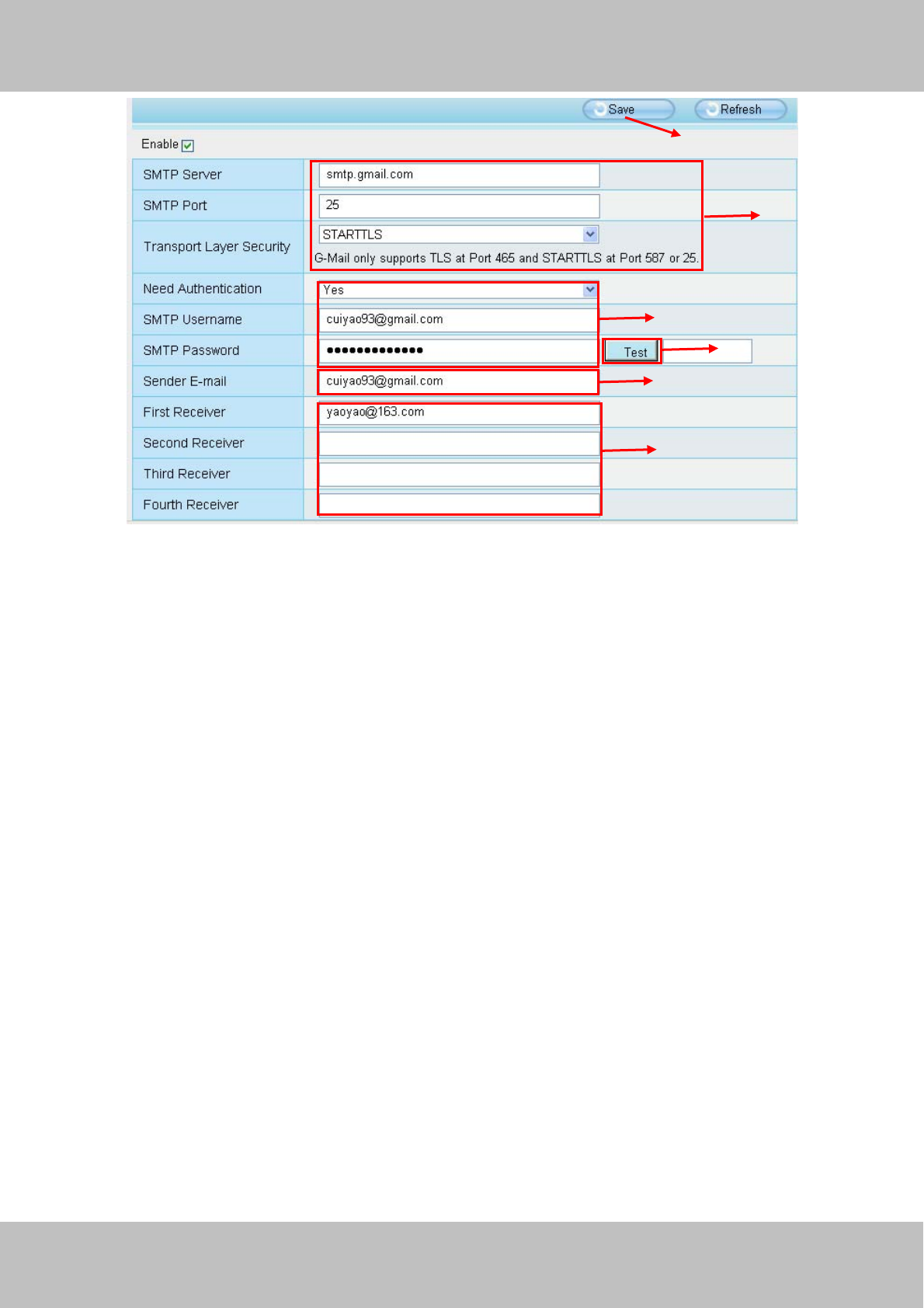
Figure 4.36
1----- SMTP Server/ Port /Transport Layer Security Enter SMTP server for sender. SMTP port is usually
set as 25. Some SMTP servers have their own port, such as 587 or 465, and Transport Layer Security usually
is None. If you use Gmail, Transport Layer Security must be set to TLS or STARTTLS and SMTP Port must be
set to 465 or 25 or 587, which port you choose should be decided by which Transport Layer Security you
select.
2-----SMTP Username/ password: ID account and password of the sender email address
3----- Sender E-mail Mailbox for sender must support SMTP
4----- Receiver Mailbox for receiver need not support SMTP, you can set 4 receivers
5----- Save Click Save to take effect
6----- Test Click Test to see if Mail has been successfully configured.
Click Test to see if Mail has been successfully configured.
1
2
3
4
5
6

w
ww
ww
w.
.f
fo
os
sc
ca
am
m.
.c
co
om
m
S
Sh
he
en
nz
zh
he
en
n
F
Fo
os
sc
ca
am
m
I
In
nt
te
el
ll
li
ig
ge
en
nt
t
T
Te
ec
ch
hn
no
ol
lo
og
gy
y
C
Co
o.
.,
,
L
Li
im
mi
it
te
ed
d
T
Te
el
l:
:
8
86
6
7
75
55
5
2
26
67
74
4
5
56
66
68
8
F
Fa
ax
x:
:
8
86
6
7
75
55
5
2
26
67
74
4
5
51
16
68
8
51
Figure 4.37
If the test success, you can see the Success behind the Test, at the same time the receivers will receive a test
mail.
If the test fails with one of the following errors after clicking Test, verify that the information you entered is
correct and again select Test .
1) Cannot connect to the server
2) Network Error. Please try later
3) Server Error
4) Incorrect user or password
5) The sender is denied by the server. Maybe the server need to authenticate the user, please check it and try
again
6) The receiver is denied by the server. Maybe because of the anti-spam privacy of the server
7) The message is denied by the server. Maybe because of the anti-spam privacy of the server
8) The server does not support the authentication mode used by the device
4.4.8 FTP Settings
If you want to upload record images to your FTP server,you can set FTP Settings.
Test result .
w
ww
ww
w.
.f
fo
os
sc
ca
am
m.
.c
co
om
m
S
Sh
he
en
nz
zh
he
en
n
F
Fo
os
sc
ca
am
m
I
In
nt
te
el
ll
li
ig
ge
en
nt
t
T
Te
ec
ch
hn
no
ol
lo
og
gy
y
C
Co
o.
.,
,
L
Li
im
mi
it
te
ed
d
T
Te
el
l:
:
8
86
6
7
75
55
5
2
26
67
74
4
5
56
66
68
8
F
Fa
ax
x:
:
8
86
6
7
75
55
5
2
26
67
74
4
5
51
16
68
8
52
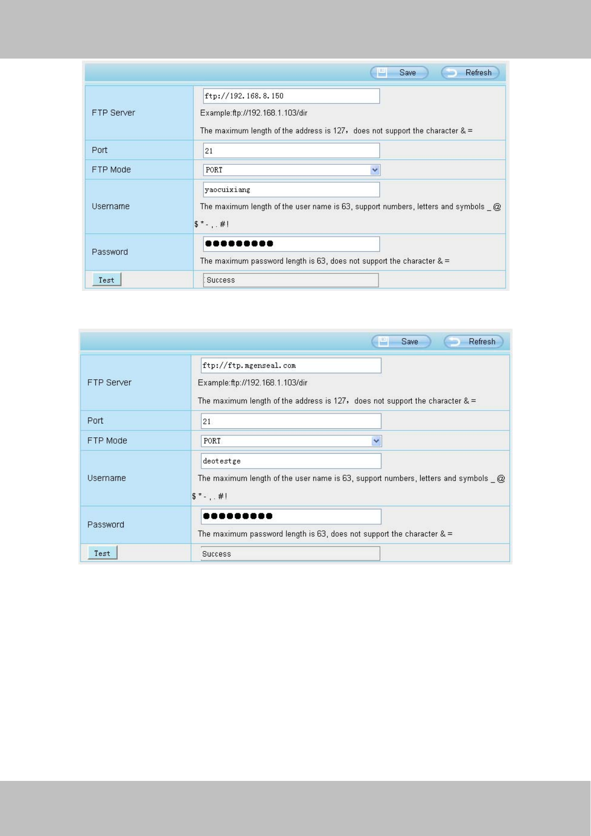
Figure 4.38
Figure 4.39
FTP server: If your FTP server is located on the LAN, you can set as Figure 4.40.
If you have an FTP server which you can access on the internet, you can set as Figure 4.41.
Port: Default is port 21. If changed, external FTP client program must change the server connection port
accordingly.
FTP Mode: Here supports two modes: PORT and PASV.
Username/password: The FTP account and password.
Click Save to take effect.
Click Test to see if FTP has been successfully configured.
w
ww
ww
w.
.f
fo
os
sc
ca
am
m.
.c
co
om
m
S
Sh
he
en
nz
zh
he
en
n
F
Fo
os
sc
ca
am
m
I
In
nt
te
el
ll
li
ig
ge
en
nt
t
T
Te
ec
ch
hn
no
ol
lo
og
gy
y
C
Co
o.
.,
,
L
Li
im
mi
it
te
ed
d
T
Te
el
l:
:
8
86
6
7
75
55
5
2
26
67
74
4
5
56
66
68
8
F
Fa
ax
x:
:
8
86
6
7
75
55
5
2
26
67
74
4
5
51
16
68
8
53
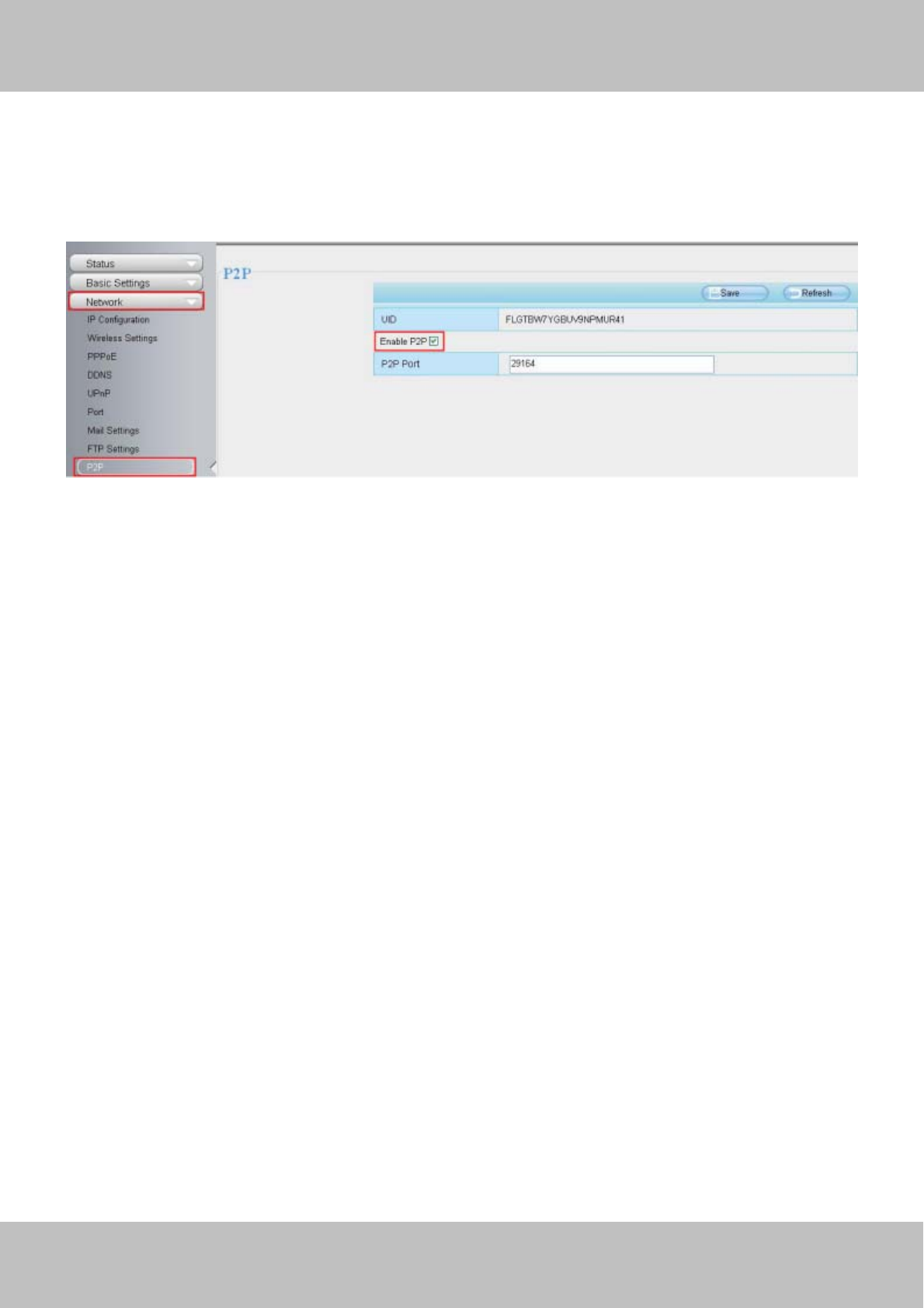
4.4.9 P2P (FI9803P/FI9803EP/FI9903P/FI9900P)
Access the camera by smart phone (Android or iOS operating system),please refer to the Quick Installation
Guide.
First of all, you need to open the P2P function of the camera at “Settings-->Network-->P2P.”
Figure 4.40
4.5 Video
This section allows you to configure Video stream settings, On screen display and Snapshot settings.
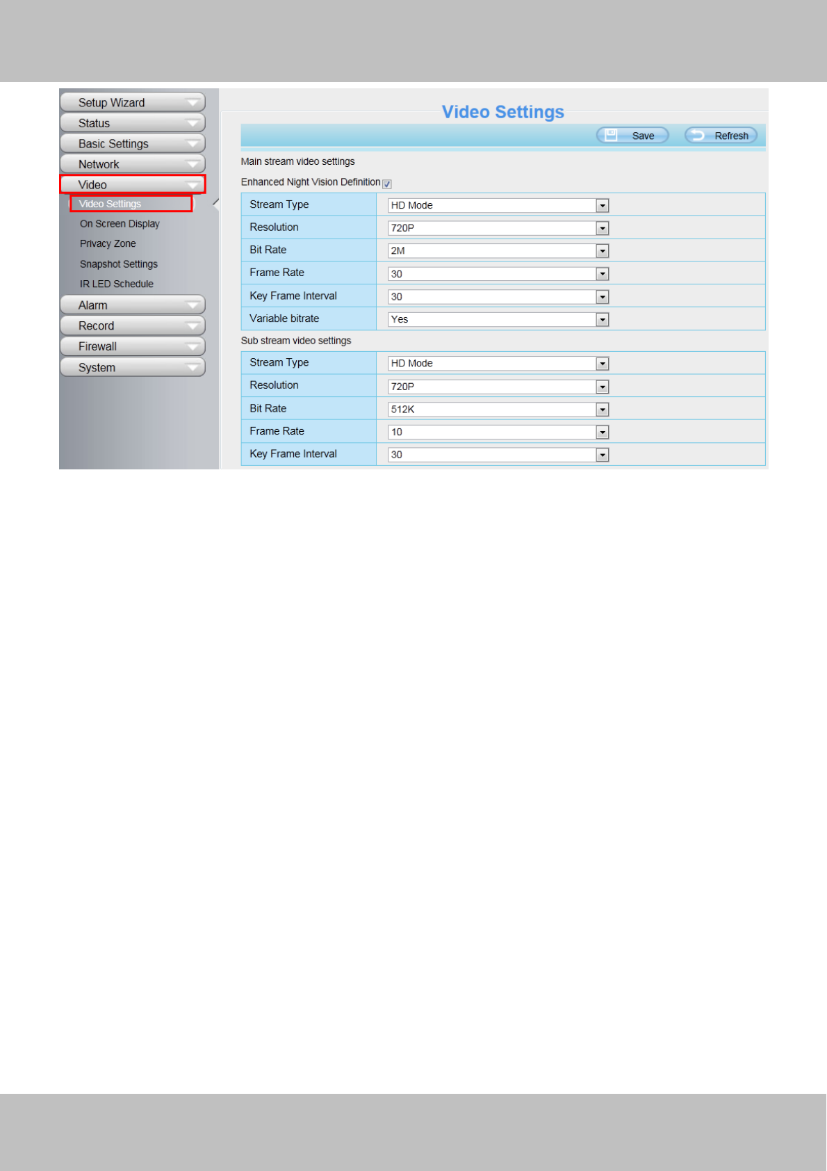
4.5.1 Video Settings
There are two ways to set the stream video settings. They are main stream video settings and sub stream
video settings.
w
ww
ww
w.
.f
fo
os
sc
ca
am
m.
.c
co
om
m
S
Sh
he
en
nz
zh
he
en
n
F
Fo
os
sc
ca
am
m
I
In
nt
te
el
ll
li
ig
ge
en
nt
t
T
Te
ec
ch
hn
no
ol
lo
og
gy
y
C
Co
o.
.,
,
L
Li
im
mi
it
te
ed
d
T
Te
el
l:
:
8
86
6
7
75
55
5
2
26
67
74
4
5
56
66
68
8
F
Fa
ax
x:
:
8
86
6
7
75
55
5
2
26
67
74
4
5
51
16
68
8
54
Figure 4.41
Enhanced Night video Definition: The camera will automatically drop the frame to extend the recording time
in the night.
Stream Type: There are four types to identify different streams you have set. If select the HD Mode, the
clearer video will become, and it will take up more bandwidth; If select the Smooth Mode, the bandwidth is very
narrow, and bit rate is large, that will lead to video can not play well. The Equilibrium Model is a value between
HD Mode and Smooth Mode.
Resolution: The camera supports multiple types, For example: 1080P, 960P, 720P, VGA. The higher the
resolution is, the clearer video will become. But the code flux will become larger too, and it will take up more
bandwidth. (Different models support different specific types. )
Bit Rate: Generally speaking, the larger the bit rate is, the clearer video will become. But the bit rate
configuration should combine well with the network bandwidth. When the bandwidth is very narrow, and bit
rate is large, that will lead to video can not play well.
Frame Rate: Note that a larger frame size takes up more bandwidth. You should lower frame rate when the
bandwidth is limited. Normally, when the frame rate above 15, you can achieve fluently video.The maximum
frame rate for each model is different, please see the “Specifications”.
Key Frame Interval: The time between last key frame and next key frame. The shorter the duration, the more
likely you will get a better video quality, but at the cost of higher network bandwidth consumption.
Variable bitrate(except for FI9900P): Select the Bit rate type to constant or variable. If select Yes, the camera
will change the video bit rate according to the situation, but will not more than the maximum parameter "Bit
Rate"; If select No, the Bit Rate is unchanged.
Rate Control Mode(Only FI9900P):There are three rate control modes.
CBR: Constant Bit Rate, it means that the Bit Rate is constant.

w
ww
ww
w.
.f
fo
os
sc
ca
am
m.
.c
co
om
m
S
Sh
he
en
nz
zh
he
en
n
F
Fo
os
sc
ca
am
m
I
In
nt
te
el
ll
li
ig
ge
en
nt
t
T
Te
ec
ch
hn
no
ol
lo
og
gy
y
C
Co
o.
.,
,
L
Li
im
mi
it
te
ed
d
T
Te
el
l:
:
8
86
6
7
75
55
5
2
26
67
74
4
5
56
66
68
8
F
Fa
ax
x:
:
8
86
6
7
75
55
5
2
26
67
74
4
5
51
16
68
8
55
VBR: Variable Bit Rate, the camera will change the video bit rate according to the situation, but will not more
than the maximum parameter "Bit Rate".
LBR: Low Bit Rate. If you can select the LBR, then you can slide the scroll bar to choose percentage of the bit
rate. By reducing the bit rate, so that the camera can obtain a better image at low bandwidth.
4.5.2 On Screen Display
This page is used to add timestamp and device name on the video.
Figure 4.42
Display Timestamp: There are two options: Yes or NO. Select Yes and you can see the system date on the
video.
Display Camera Name: There are two options: Yes or NO. Select Yes and you can see the device name on
the video.
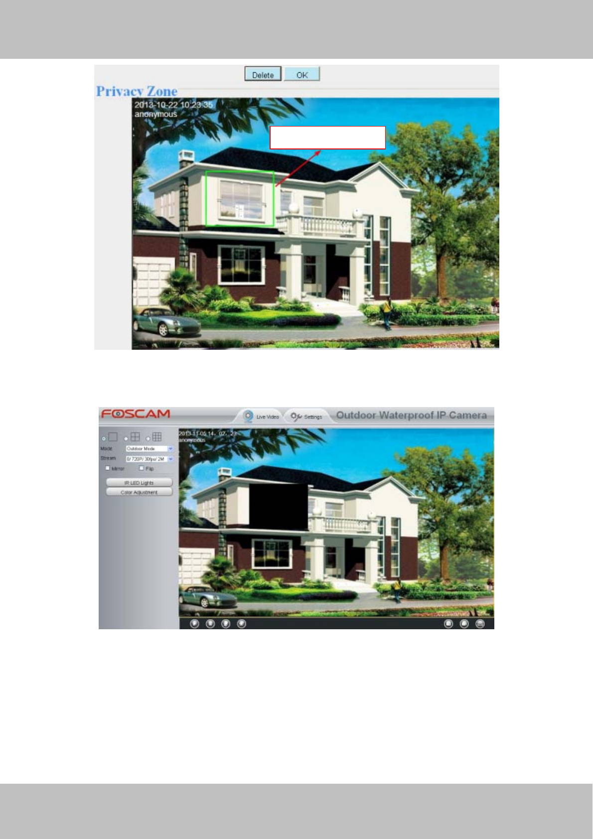
4.5.3 Privacy Zone
Some models do not support this Function.
This page is used to add privacy zone on the video.
Figure 4.43
Allow On Screen Display Mask
There are two options: Yes or NO. Select yes and draw a mask area on the video, the mask area will be black
on the video.
w
ww
ww
w.
.f
fo
os
sc
ca
am
m.
.c
co
om
m
S
Sh
he
en
nz
zh
he
en
n
F
Fo
os
sc
ca
am
m
I
In
nt
te
el
ll
li
ig
ge
en
nt
t
T
Te
ec
ch
hn
no
ol
lo
og
gy
y
C
Co
o.
.,
,
L
Li
im
mi
it
te
ed
d
T
Te
el
l:
:
8
86
6
7
75
55
5
2
26
67
74
4
5
56
66
68
8
F
Fa
ax
x:
:
8
86
6
7
75
55
5
2
26
67
74
4
5
51
16
68
8
56
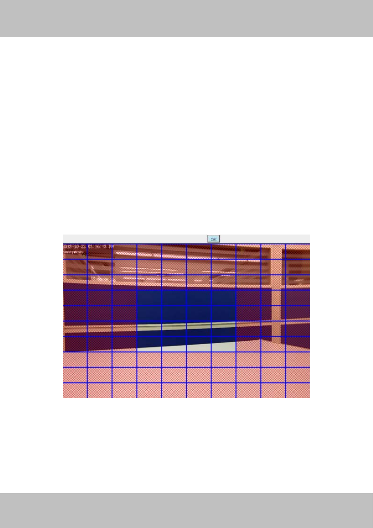
Figure 4.44
Click OK button and return to the Privacy Zone page, click Save to take effect.
Back to the surveillance window, you can see the privacy area as the following picture:
Figure 4.45
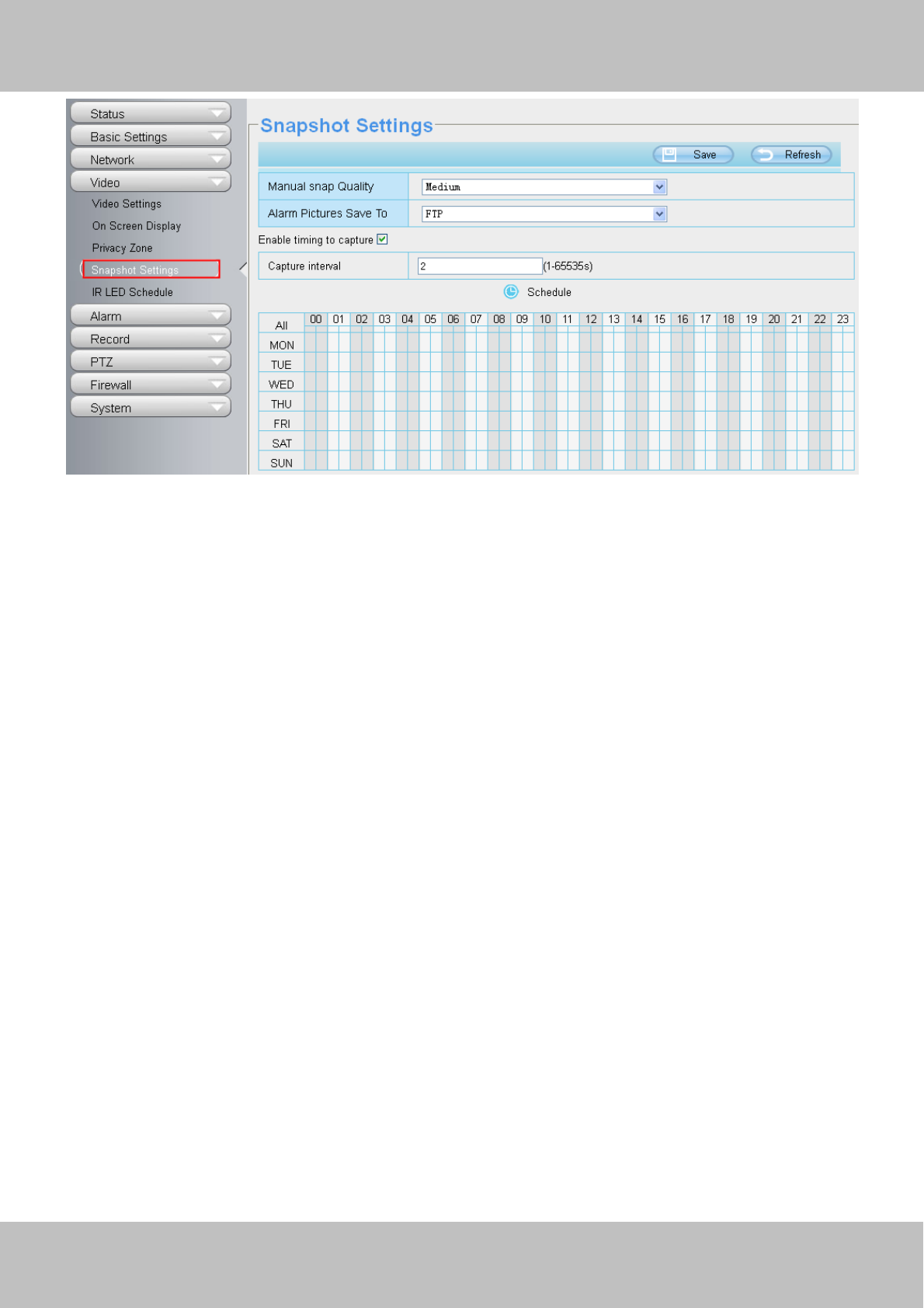
4.5.4 Snapshot Settings
On this page you can set the snapshot pictures’ image quality and the storage path.
The privacy zone
w
ww
ww
w.
.f
fo
os
sc
ca
am
m.
.c
co
om
m
S
Sh
he
en
nz
zh
he
en
n
F
Fo
os
sc
ca
am
m
I
In
nt
te
el
ll
li
ig
ge
en
nt
t
T
Te
ec
ch
hn
no
ol
lo
og
gy
y
C
Co
o.
.,
,
L
Li
im
mi
it
te
ed
d
T
Te
el
l:
:
8
86
6
7
75
55
5
2
26
67
74
4
5
56
66
68
8
F
Fa
ax
x:
:
8
86
6
7
75
55
5
2
26
67
74
4
5
51
16
68
8
57
Figure 4.46
Image Quality: Low, Middle and High. The higher the quality, the picture will be clearer.
Alarm Pictures Save Path:
z FTP: If you have done FTP and Alarm settings, when alarming, the camera will snap pictures to the FTP
automatically.
z SD(FI9803EP/FI9900P): If select SD Card as the save path, make sure the camera has inserted in the SD
card.
Enable timing to capture
To enable capture interval, follow the steps below:
1 Select Enable timing to capture
2 Capture interval:The interval time between two captures.
3 Select the capture time
z Capture anytime
Click the black button up the MON, you will see all time range turn red. When something moving in the
detection area at anytime, the camera will capture.
z Specify an capture schedule
Click the week day words, the corresponding column will be selected. For example, click TUE, the all
column of TUE turns to red, that means during Tuesday whole day, the camera will capture.
z Press the left mouse and drag it on the time boxes, you can select the serial area,
4 Click Save button to take effect.
4.5.5 IR LED Schedule
On this page you can set the schedule time for switching IR LED lights. When parameter Mode is set to the
Schedule on the Live Video window, At these schedule time, the IR LED lights will be turned off.

w
ww
ww
w.
.f
fo
os
sc
ca
am
m.
.c
co
om
m
S
Sh
he
en
nz
zh
he
en
n
F
Fo
os
sc
ca
am
m
I
In
nt
te
el
ll
li
ig
ge
en
nt
t
T
Te
ec
ch
hn
no
ol
lo
og
gy
y
C
Co
o.
.,
,
L
Li
im
mi
it
te
ed
d
T
Te
el
l:
:
8
86
6
7
75
55
5
2
26
67
74
4
5
56
66
68
8
F
Fa
ax
x:
:
8
86
6
7
75
55
5
2
26
67
74
4
5
51
16
68
8
58
Figure 4.47
4.5.6 Lens Distortion Correction
On this page you can set the distortion correction. There are three options: Low, Medium, High.
Figure 4.48
If you replace the lens, the image has found distortion, uneven and so on, you can modify the Select The
Distortion Correction Parameter to calibration images.
4.6 Alarm
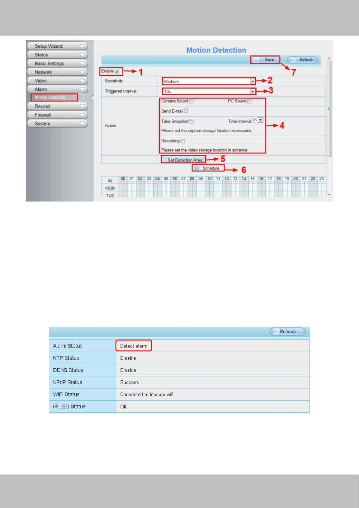
4.6.1 Motion Detection
IP Camera supports Motion Detection Alarm, when the motion has been detected, it will send emails or
upload images to FTP.
w
ww
ww
w.
.f
fo
os
sc
ca
am
m.
.c
co
om
m
S
Sh
he
en
nz
zh
he
en
n
F
Fo
os
sc
ca
am
m
I
In
nt
te
el
ll
li
ig
ge
en
nt
t
T
Te
ec
ch
hn
no
ol
lo
og
gy
y
C
Co
o.
.,
,
L
Li
im
mi
it
te
ed
d
T
Te
el
l:
:
8
86
6
7
75
55
5
2
26
67
74
4
5
56
66
68
8
F
Fa
ax
x:
:
8
86
6
7
75
55
5
2
26
67
74
4
5
51
16
68
8
59
Figure 4.49
To enable motion detection, follow the steps below:
1 Enable Motion detection
2 Sensitivity---- It supports three modes: Low, Middle and High. The higher the sensitivity, the camera will be
more easily alarmed. Select one motion sensitivity.
3 Trigger interval--- The interval time between two motion detections. Here supports
5s/6s/7s/8s/9s/10s/11s/12s/13s/14s/15s. Select one interval time.
4 Select the alarm indicators
When the motion has been detected, the alarm status will turn to Detect alarm.
Figure 4.50
There are four alarm indicators:
A Camera Sound and PC Sound
If the camera has connected with a speaker or other audio output device, if you select Camera Sound or PC
Sound, when the motion has been detected, the people around the camera will hear beep alarm sound.
w
ww
ww
w.
.f
fo
os
sc
ca
am
m.
.c
co
om
m
S
Sh
he
en
nz
zh
he
en
n
F
Fo
os
sc
ca
am
m
I
In
nt
te
el
ll
li
ig
ge
en
nt
t
T
Te
ec
ch
hn
no
ol
lo
og
gy
y
C
Co
o.
.,
,
L
Li
im
mi
it
te
ed
d
T
Te
el
l:
:
8
86
6
7
75
55
5
2
26
67
74
4
5
56
66
68
8
F
Fa
ax
x:
:
8
86
6
7
75
55
5
2
26
67
74
4
5
51
16
68
8
60
B Send E-mail
If you want to receive alarm emails when motion is detected, you must select Send E-mail and set Mail
Settings first.
C Take Snapshot
If you select this checkbox, when the motion has been detected, the camera will snap the live view window as
a still picture and load it to the FTP. Make sure you have set FTP and set FTP as the storage path in
Video->Snapshot settings panel.
Time interval: The interval time between two pictures.
D Recording
If you select this checkbox, when the motion has been detected, the camera will recording and load it to the
FTP server. Make sure you have set FTP and set FTP as the storage path in Video->Snapshot settings panel.
5 Set detect area
Click set detect area and it pop up a window, then you can draw the detection area. Click Back button after
settings. When something moving in the detection area, the camera will alarm.
Figure 4.51
6 Alarm Schedule
Alarm anytime when ①motion is detected
Click the black button up the MON, you will see all time range turn red. When something moving in the
detection area at anytime, the camera will alarm.

w
ww
ww
w.
.f
fo
os
sc
ca
am
m.
.c
co
om
m
S
Sh
he
en
nz
zh
he
en
n
F
Fo
os
sc
ca
am
m
I
In
nt
te
el
ll
li
ig
ge
en
nt
t
T
Te
ec
ch
hn
no
ol
lo
og
gy
y
C
Co
o.
.,
,
L
Li
im
mi
it
te
ed
d
T
Te
el
l:
:
8
86
6
7
75
55
5
2
26
67
74
4
5
56
66
68
8
F
Fa
ax
x:
:
8
86
6
7
75
55
5
2
26
67
74
4
5
51
16
68
8
61
Figure 4.52
Specify an alarm schedule②
Click the week day words, the corresponding column will be selected. For example, click TUE, the all column
of TUE turns to red, that means during Tuesday whole day, when something moving in the detection area, the
camera will alarm.
Figure 4.53
Press the left mouse and drag it on the time boxes, you can select t③he serial area,
Figure 4.54
7 Click Save button to take effect. When the motion is detected during the detection time in the detection area,
Click this button and select all time range .
w
ww
ww
w.
.f
fo
os
sc
ca
am
m.
.c
co
om
m
S
Sh
he
en
nz
zh
he
en
n
F
Fo
os
sc
ca
am
m
I
In
nt
te
el
ll
li
ig
ge
en
nt
t
T
Te
ec
ch
hn
no
ol
lo
og
gy
y
C
Co
o.
.,
,
L
Li
im
mi
it
te
ed
d
T
Te
el
l:
:
8
86
6
7
75
55
5
2
26
67
74
4
5
56
66
68
8
F
Fa
ax
x:
:
8
86
6
7
75
55
5
2
26
67
74
4
5
51
16
68
8
62
the camera will alarm and adopt the corresponding alarm indicators.
NOTE: You must set the detection area and detection schedule, or else there is no alarm anywhere and
anytime.
4.6.2 IO Alarm(only FI9805E)
This IP camera provides a IO alarm terminal block which is used to connect to external input / output device.
The alarm device(door sensor, infrared sensor, smoke detectors, etc) send input command to the network
camera, then the network camera send output command to the alarm output device(local audible alarm, lights
alarm,etc.
Figure 4.55
There is an IO alarm input/output lines in the FOSCAM camera tails. Enable IO alarm need this cable to
connect to the alarm device (door sensor, infrared sensor, smoke detector, etc.).
I/O Alarm has four ports:
z Port 1 and port 2 indicate IO alarm input
z Port 3 and port 4 indicate IO alarm output
w
ww
ww
w.
.f
fo
os
sc
ca
am
m.
.c
co
om
m
S
Sh
he
en
nz
zh
he
en
n
F
Fo
os
sc
ca
am
m
I
In
nt
te
el
ll
li
ig
ge
en
nt
t
T
Te
ec
ch
hn
no
ol
lo
og
gy
y
C
Co
o.
.,
,
L
Li
im
mi
it
te
ed
d
T
Te
el
l:
:
8
86
6
7
75
55
5
2
26
67
74
4
5
56
66
68
8
F
Fa
ax
x:
:
8
86
6
7
75
55
5
2
26
67
74
4
5
51
16
68
8
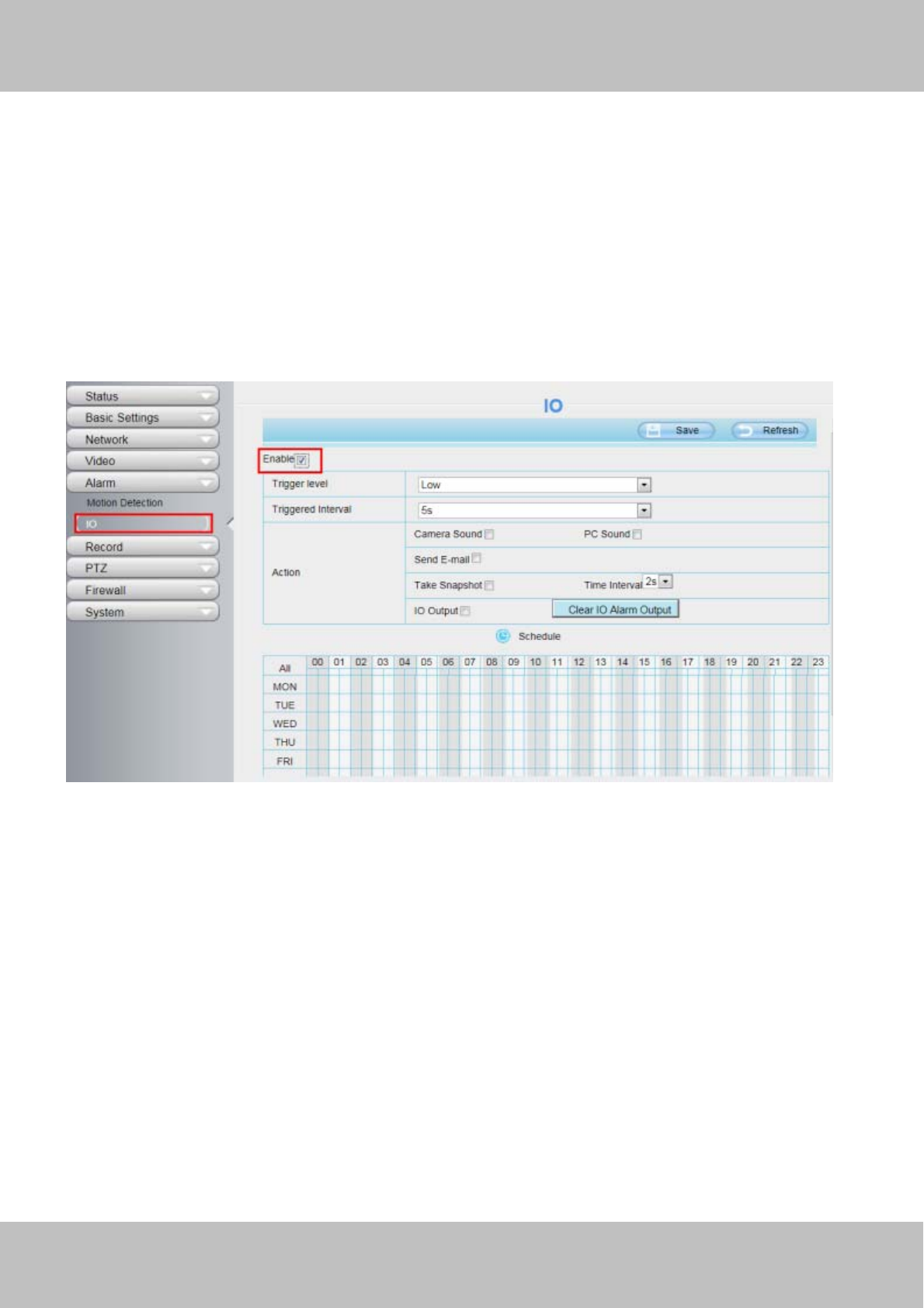
63
Figure 4.56
Setting IO alarm
On the IO page, Enable the I/O alarm, select the “Send E-mail”and ”Snapshot” before you have configured
the mail and FTP.
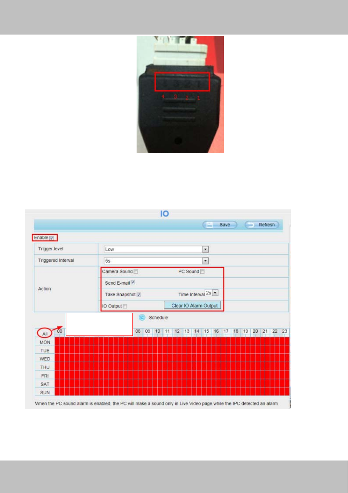
Figure 4.57
If an IO alarm is triggered and IO alarm output device will always alarm (sound alarm is issued a warning
sound, alarm lights in flash etc.). Click "Clear IO alarm output" , the alarm output device will stop alarming. If IO
alarm is triggered again after alarm interval, IO alarm output device will be restart.
Click this button and
select all time range.
w
ww
ww
w.
.f
fo
os
sc
ca
am
m.
.c
co
om
m
S
Sh
he
en
nz
zh
he
en
n
F
Fo
os
sc
ca
am
m
I
In
nt
te
el
ll
li
ig
ge
en
nt
t
T
Te
ec
ch
hn
no
ol
lo
og
gy
y
C
Co
o.
.,
,
L
Li
im
mi
it
te
ed
d
T
Te
el
l:
:
8
86
6
7
75
55
5
2
26
67
74
4
5
56
66
68
8
F
Fa
ax
x:
:
8
86
6
7
75
55
5
2
26
67
74
4
5
51
16
68
8
64
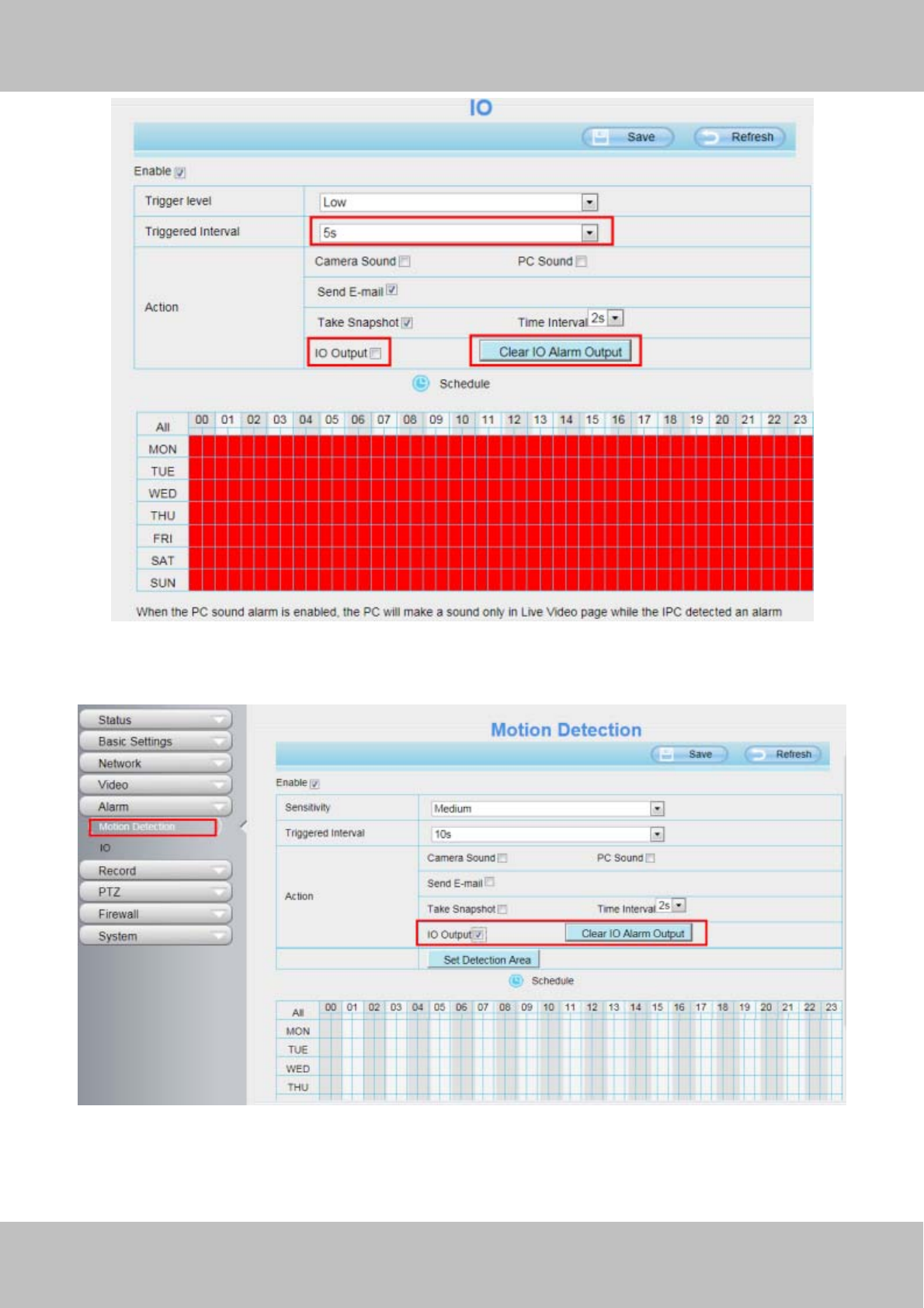
Figure 4.58
Note: motion detection alarm can also be triggered IO alarm output.
Figure 4.59

w
ww
ww
w.
.f
fo
os
sc
ca
am
m.
.c
co
om
m
S
Sh
he
en
nz
zh
he
en
n
F
Fo
os
sc
ca
am
m
I
In
nt
te
el
ll
li
ig
ge
en
nt
t
T
Te
ec
ch
hn
no
ol
lo
og
gy
y
C
Co
o.
.,
,
L
Li
im
mi
it
te
ed
d
T
Te
el
l:
:
8
86
6
7
75
55
5
2
26
67
74
4
5
56
66
68
8
F
Fa
ax
x:
:
8
86
6
7
75
55
5
2
26
67
74
4
5
51
16
68
8
65
4.7 Record
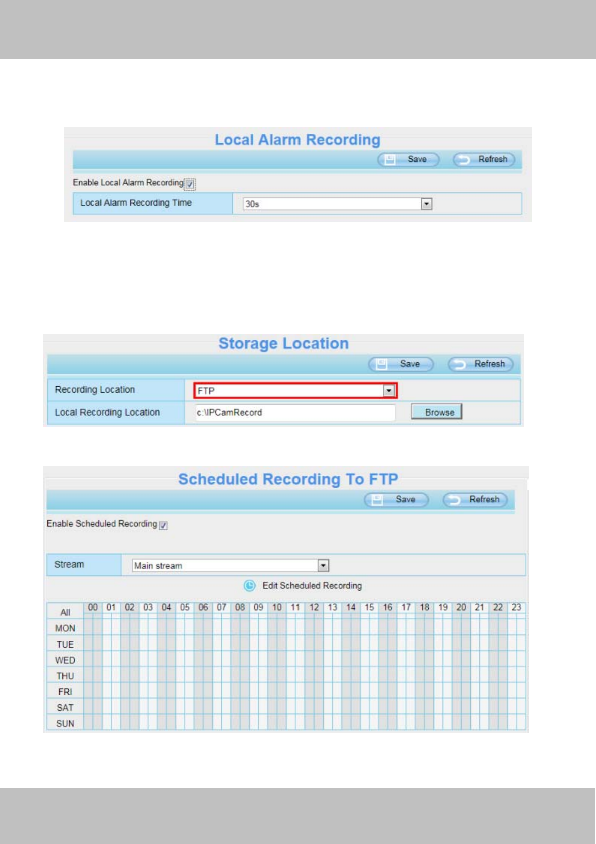
4.7.1 Storage Location
Figure 4.60
Recording Location : SD card, FTP.
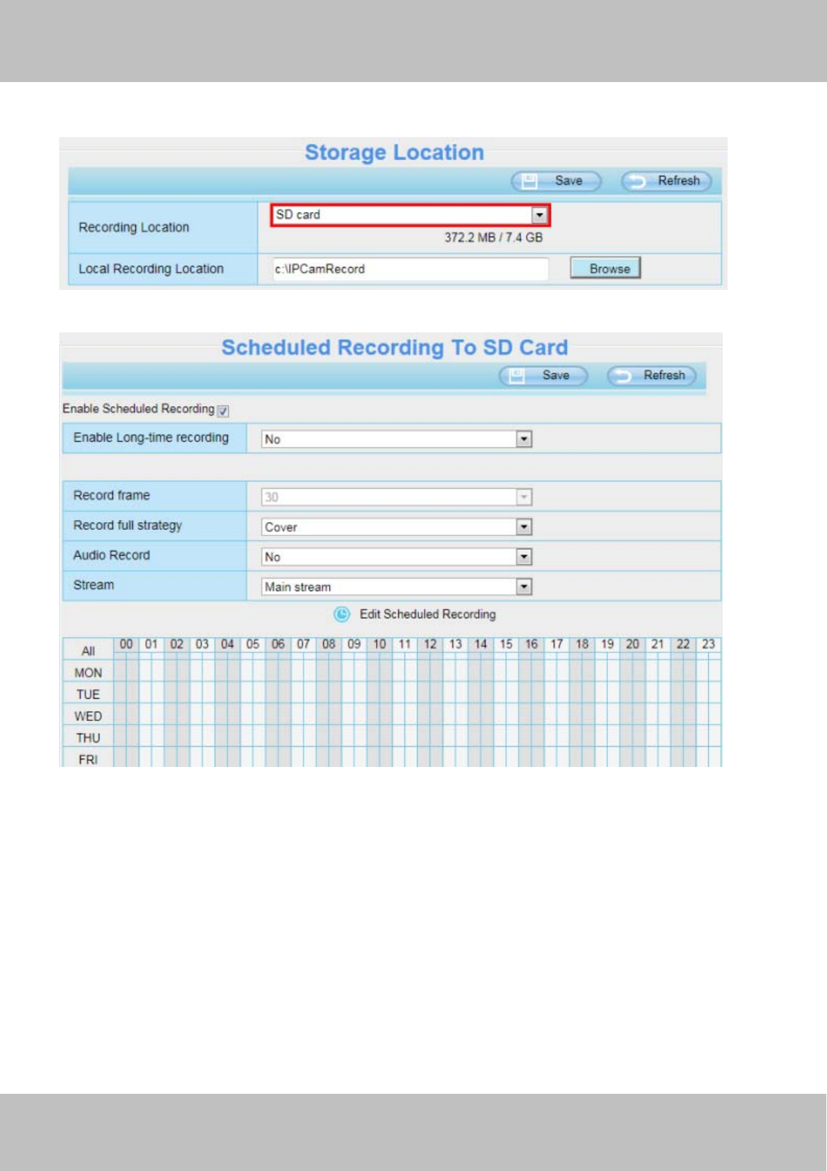
z SD card(Only FI9803EP/FI9900P): The video will be saved in SD card. Make sure the camera has been
inserted the SD card. On this page, you can see the available space of the SD card.
z FTP: The video will be saved in FTP. Please refer to "FTP settings."
Local Recording Location: For Windows OS, the manual recording path is C:/ IPCamRecord, you can
change another one. For MAC OS, the manual recording path is: / IPCamRecord.
Enter the local folder :Click here,you can enter the local folder.
4.7.2 Alarm Record
Figure 4.61
w
ww
ww
w.
.f
fo
os
sc
ca
am
m.
.c
co
om
m
S
Sh
he
en
nz
zh
he
en
n
F
Fo
os
sc
ca
am
m
I
In
nt
te
el
ll
li
ig
ge
en
nt
t
T
Te
ec
ch
hn
no
ol
lo
og
gy
y
C
Co
o.
.,
,
L
Li
im
mi
it
te
ed
d
T
Te
el
l:
:
8
86
6
7
75
55
5
2
26
67
74
4
5
56
66
68
8
F
Fa
ax
x:
:
8
86
6
7
75
55
5
2
26
67
74
4
5
51
16
68
8
66
4.7.3 Local Alarm Location
On this page you can enable local alarm record, and select the local alarm record time.
Figure 4.62
4.7.4 Schedule Recording
When the video is selected as FTP, the device supports scheduled recording.
Figure 4.63
Figure 4.64
When the video is selected as SD card, the device supports pumping frame recording.(only FI9803EP
w
ww
ww
w.
.f
fo
os
sc
ca
am
m.
.c
co
om
m
S
Sh
he
en
nz
zh
he
en
n
F
Fo
os
sc
ca
am
m
I
In
nt
te
el
ll
li
ig
ge
en
nt
t
T
Te
ec
ch
hn
no
ol
lo
og
gy
y
C
Co
o.
.,
,
L
Li
im
mi
it
te
ed
d
T
Te
el
l:
:
8
86
6
7
75
55
5
2
26
67
74
4
5
56
66
68
8
F
Fa
ax
x:
:
8
86
6
7
75
55
5
2
26
67
74
4
5
51
16
68
8
67
and FI9900P support SD card).
Figure 4.65
Figure 4.66
Record frame: There are six frame selections, such as 1/30, 4/30, 8/30, 15/30, 24/30, 30/30. Recommended
default is 4/30. The greater the Frame rate is, the sharper picture quality is, and the greater of storage space is,
the shorter the storage time is.
Record full strategy: When the SD card is full, you can choose to cover the previous recording, or stop
recording.
Audio Record: You can choose "yes" or "no".
NOTES:
z Scheduled recording only supports video saved to the SD card or FTP server.
z The schedule recording will stop while alarm recording is beginning, and it will continue automatically after
alarm recording end.
z You can refer to "alarm schedule." in "Alarm" about editing the time of recording Schedule.
w
ww
ww
w.
.f
fo
os
sc
ca
am
m.
.c
co
om
m
S
Sh
he
en
nz
zh
he
en
n
F
Fo
os
sc
ca
am
m
I
In
nt
te
el
ll
li
ig
ge
en
nt
t
T
Te
ec
ch
hn
no
ol
lo
og
gy
y
C
Co
o.
.,
,
L
Li
im
mi
it
te
ed
d
T
Te
el
l:
:
8
86
6
7
75
55
5
2
26
67
74
4
5
56
66
68
8
F
Fa
ax
x:
:
8
86
6
7
75
55
5
2
26
67
74
4
5
51
16
68
8
68
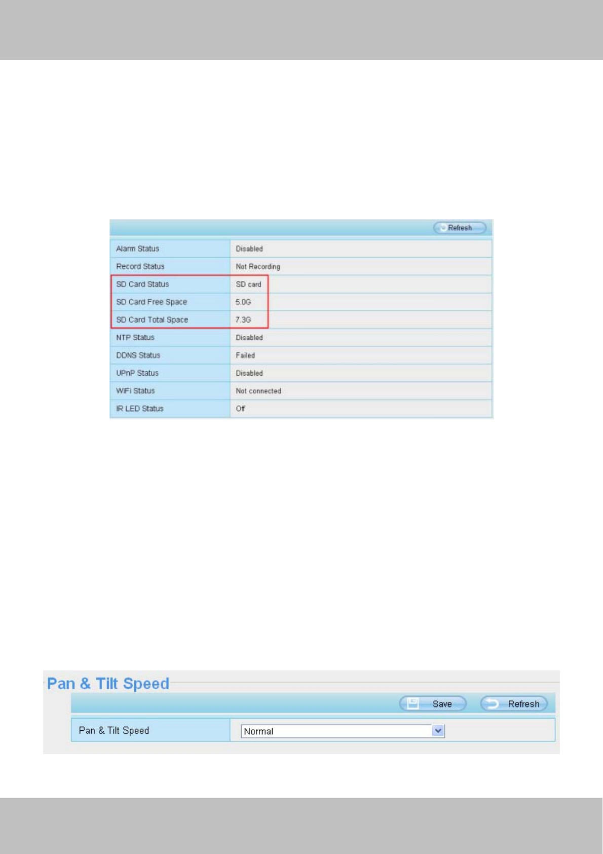
4.7.5 SD Card Management(FI9803EP/FI9900P)
The SD card Slot inside the camera, if you want to install or remove the SD card, you need to open the
camera.
When you plug in the SD card during the camera work process, please reboot the camera again, or else the
SD Card may be cannot work well.
Go to the SettingsÆStatusÆDevice Status page, you can see the SD card status.
Figure 4.67
The default storage path of alarm record files is SD card, when the available size of SD card is less than 256M,
the old record files will be deleted automatically.
4.8 PTZ(only FI9805E)
This page will allow you to change the pan/tilt speed and do RS485 settings.(Only FI9805E have this feature)
4.8.1 Pan/Tilt Speed
There are five Pt speed types: very fast, fast, normal, slow and very slowly. Select the desired pan/tilt speed
type and click save button .
Figure 4.68
w
ww
ww
w.
.f
fo
os
sc
ca
am
m.
.c
co
om
m
S
Sh
he
en
nz
zh
he
en
n
F
Fo
os
sc
ca
am
m
I
In
nt
te
el
ll
li
ig
ge
en
nt
t
T
Te
ec
ch
hn
no
ol
lo
og
gy
y
C
Co
o.
.,
,
L
Li
im
mi
it
te
ed
d
T
Te
el
l:
:
8
86
6
7
75
55
5
2
26
67
74
4
5
56
66
68
8
F
Fa
ax
x:
:
8
86
6
7
75
55
5
2
26
67
74
4
5
51
16
68
8
69
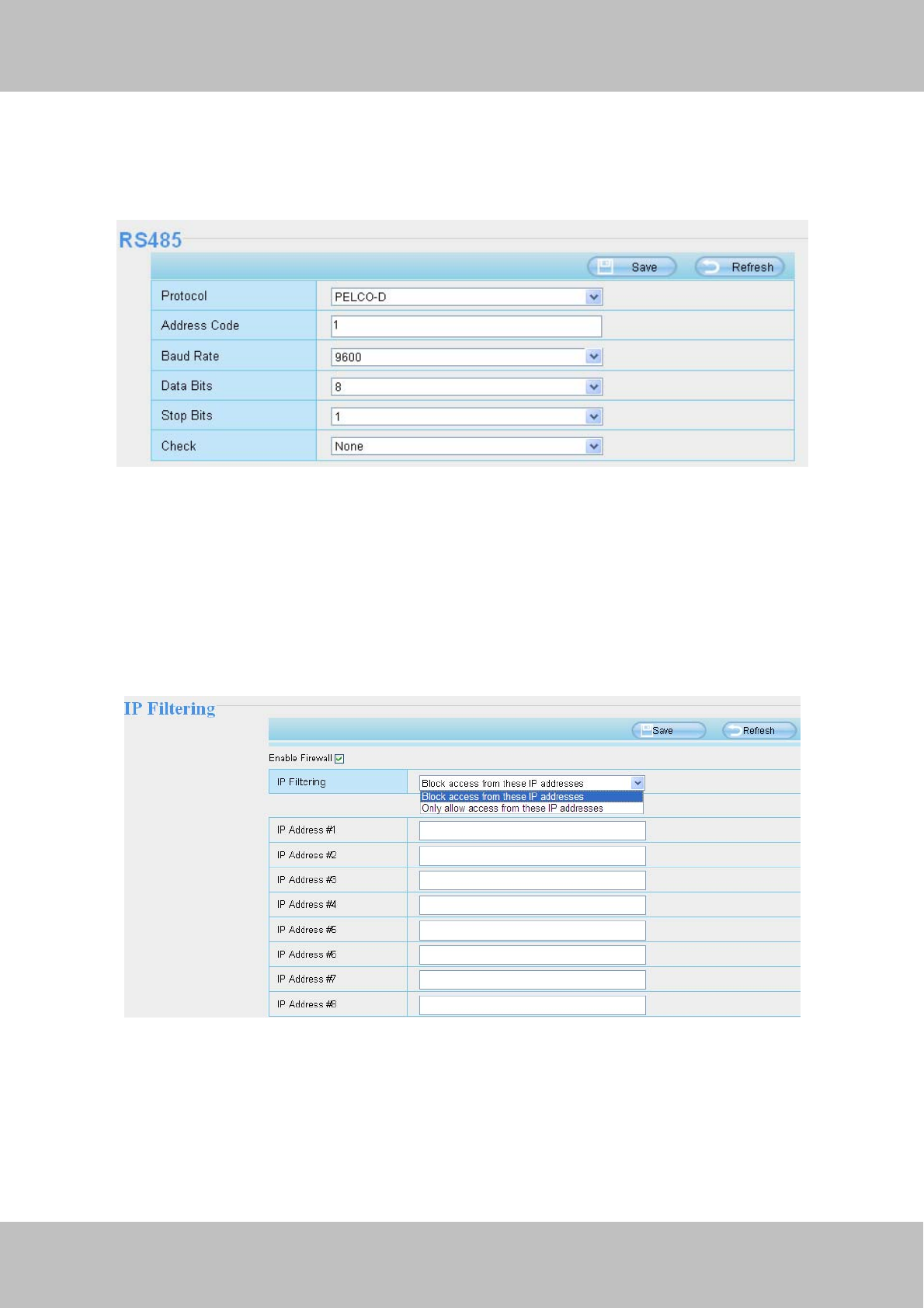
4.8.2 RS485 Configuration
This camera supports the standard 485 cradle head protocol (PELCO-D and PELCO-P). Please configure the
RS485 protocol corresponding information first, or else the cradle head may cannot work.
Figure 4.69
4.9 Firewall
This section explains how to control the access permission by checking the client PC’s IP addresses. It is
composed of the following columns: Block access from these IP addresses and Only allow access from
these IP addresses.
Figure 4.70
Enable firewall, If you select Only allow access from these IP addresses and fill in 8 IP addresses at most, only
those clients whose IP addresses listed in the Only allow access from these IP addresses can access the
Network Camera. If you select Block access from these IP addresses, only those clients whose IP addresses
are in the IP list cannot access the Network Camera.
Click Save to take effect.
w
ww
ww
w.
.f
fo
os
sc
ca
am
m.
.c
co
om
m
S
Sh
he
en
nz
zh
he
en
n
F
Fo
os
sc
ca
am
m
I
In
nt
te
el
ll
li
ig
ge
en
nt
t
T
Te
ec
ch
hn
no
ol
lo
og
gy
y
C
Co
o.
.,
,
L
Li
im
mi
it
te
ed
d
T
Te
el
l:
:
8
86
6
7
75
55
5
2
26
67
74
4
5
56
66
68
8
F
Fa
ax
x:
:
8
86
6
7
75
55
5
2
26
67
74
4
5
51
16
68
8
70
4.10 System
In this panel, you can back up/restore your camera settings, upgrade the firmware to the latest version, restore
the camera to default settings and reboot the device.
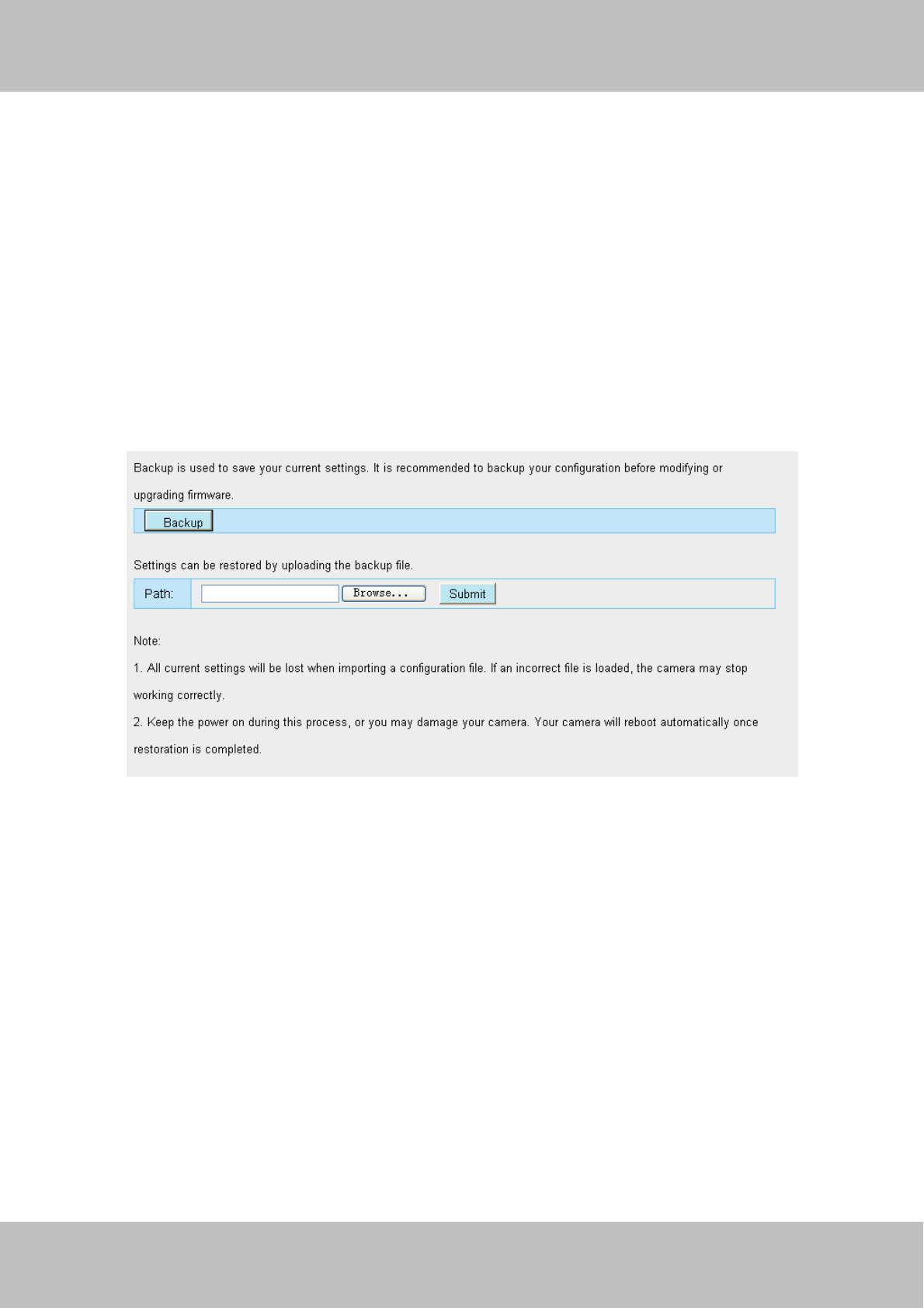
4.10.1 Back-up& Restore
Click Backup to save all the parameters you have set. These parameters will be stored in a bin file for future
use.
Click Browse and select the parameters file you have stored, then click Submit to restore the restore the
parameters.
Figure 4.71
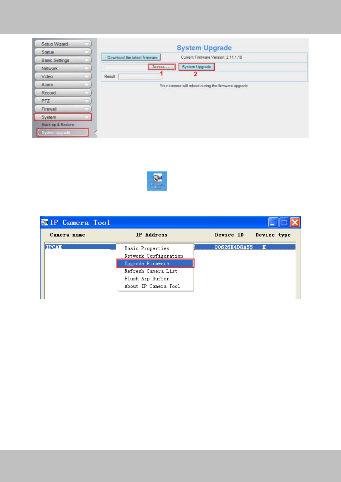
4.10.2 System Upgrade
Click “Download the latest firmware”, you will see the following screen. And click “save” to save the firmware
on your computer locally.
Your current firmware version will be displayed on your screen. You may go to the StatusÆ Device
Information page to check for the latest firmware versions available.
Click Browse, choose the correct bin file and then click System upgrade.
Don’t shut down the power during upgrading. After upgrading, you can see the upgrade result.
w
ww
ww
w.
.f
fo
os
sc
ca
am
m.
.c
co
om
m
S
Sh
he
en
nz
zh
he
en
n
F
Fo
os
sc
ca
am
m
I
In
nt
te
el
ll
li
ig
ge
en
nt
t
T
Te
ec
ch
hn
no
ol
lo
og
gy
y
C
Co
o.
.,
,
L
Li
im
mi
it
te
ed
d
T
Te
el
l:
:
8
86
6
7
75
55
5
2
26
67
74
4
5
56
66
68
8
F
Fa
ax
x:
:
8
86
6
7
75
55
5
2
26
67
74
4
5
51
16
68
8
71
Figure 4.72
Upgrade Firmware by IP Camera Tool
Double click the IP Camera Tool shot icon , select the Camera IP that you want to upgrade the
firmware. Then select Upgrade Firmware and enter the username and password, choose the firmware file, and
upgrade.
Figure 4.73