ShenZhen Foscam Intelligent Technology FI9900P Outdoor HD IP Camera User Manual Part Two
ShenZhen Foscam Intelligent Technology Co., Ltd. Outdoor HD IP Camera Users Manual Part Two
Contents
- 1. Users Manual Part One
- 2. Users Manual Part Two
- 3. Users Manual Part Three
- 4. User Manual Part Four
Users Manual Part Two

w
ww
ww
w.
.f
fo
os
sc
ca
am
m.
.c
co
om
m
S
Sh
he
en
nz
zh
he
en
n
F
Fo
os
sc
ca
am
m
I
In
nt
te
el
ll
li
ig
ge
en
nt
t
T
Te
ec
ch
hn
no
ol
lo
og
gy
y
C
Co
o.
.,
,
L
Li
im
mi
it
te
ed
d
T
Te
el
l:
:
8
86
6
7
75
55
5
2
26
67
74
4
5
56
66
68
8
F
Fa
ax
x:
:
8
86
6
7
75
55
5
2
26
67
74
4
5
51
16
68
8
24
Section1 FOSCAM Logo/ LiveVideo / Settings buttons
: FOSCAM LOGO
: Path to surveillance window. Click this button and back to the surveillance window
: Path to Administrator Control Panel, Click it, and it will lead to Administrator Control Panel and
do advanced settings.
Section2 Multi-Device Window
The firmware inside the camera supports up to maximum of 9 cameras being monitoring at the same time. You
can add other cameras in multi-camera panel.
Section3 Mode/ Stream / Mirror/ Flip buttons
Mode
1) 50Hz ---------Indoor surveillance (Region: Europe, China)
2) 60Hz ---------Indoor surveillance (Region: USA, Canada)
3) Outdoor Mode------Outdoor surveillance
Stream
The default stream supports multiple modes, For example: HD Mode/720P/30fps/2M meanings: Stream type /
Resolution / Maximum frame rate/ Bit rate. (Different models support different specific mode. )
1) Stream type no. : Identify the stream type.
2) Resolution
The bigger the resolution, the better of the image quality is. If you are accessing the camera via internet and
want to get more fluent video streaming, please select resolution VGA.
3) Maximum frame rate
The maximum frame rate is 30 fps. You should lower frame rate when the bandwidth is limited. Normally, when
the frame rate above 15, you can achieve fluently video. The maximum frame rate for each model is different,
please see the “Specifications”.
4) Bit rate
Generally speaking, the larger the bit rate is, the clearer video will become. But the bit rate configuration should
combine well with the network bandwidth. When the bandwidth is very narrow, and bit rate is large, that will
lead to video cannot play well.
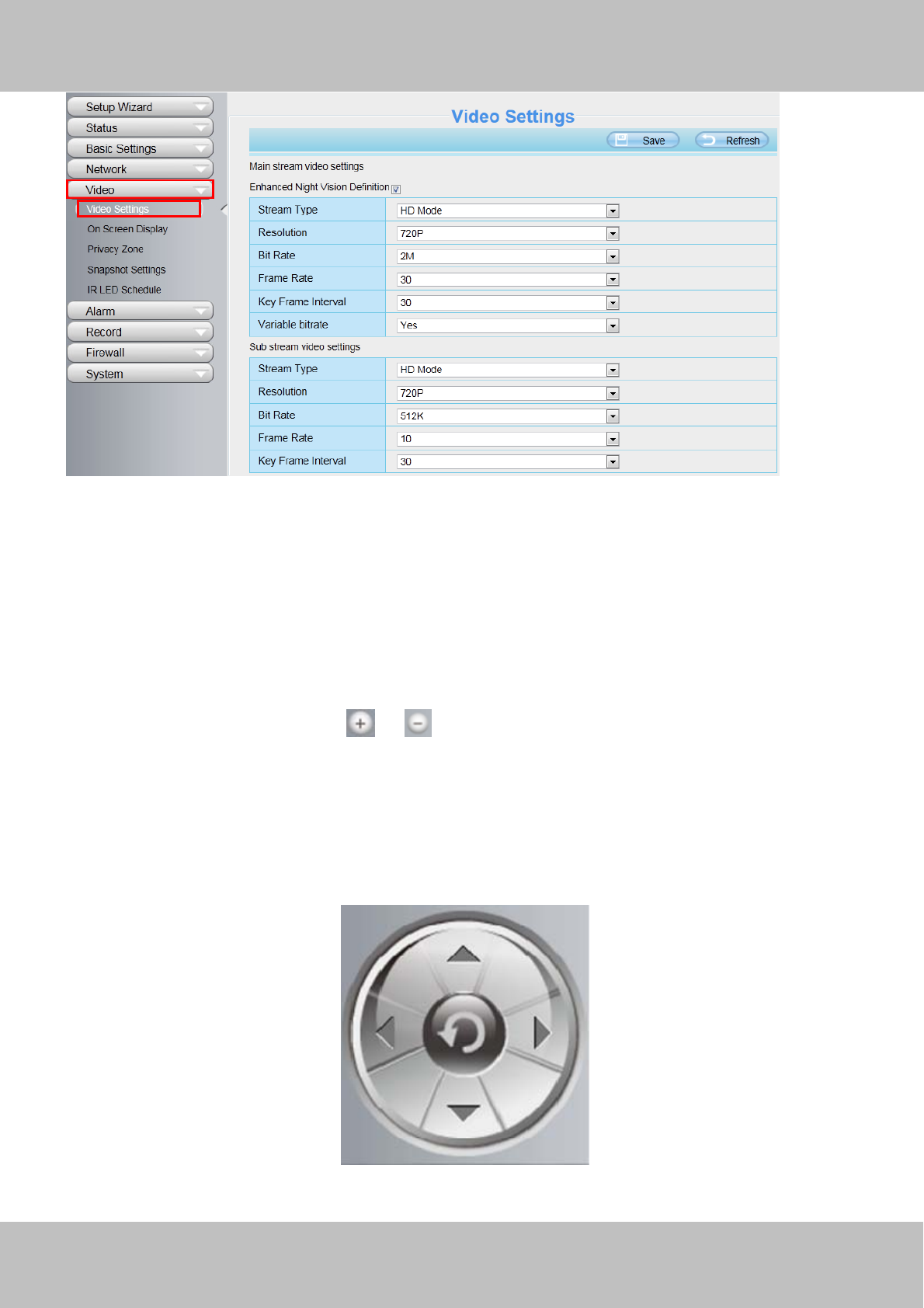
You can reset the stream type on “Settings-> Video-> Video Settings” panel.
w
ww
ww
w.
.f
fo
os
sc
ca
am
m.
.c
co
om
m
S
Sh
he
en
nz
zh
he
en
n
F
Fo
os
sc
ca
am
m
I
In
nt
te
el
ll
li
ig
ge
en
nt
t
T
Te
ec
ch
hn
no
ol
lo
og
gy
y
C
Co
o.
.,
,
L
Li
im
mi
it
te
ed
d
T
Te
el
l:
:
8
86
6
7
75
55
5
2
26
67
74
4
5
56
66
68
8
F
Fa
ax
x:
:
8
86
6
7
75
55
5
2
26
67
74
4
5
51
16
68
8
25
Figure 3.10
HDR(Only FI9900P): HDR stands for High Dynamic Range. It usually refers to the method of capturing images
having “greater dynamic range between the lightest and darkest areas of an image than current standard
digital imaging methods or photographic methods”. You can select “on” from the dropdown list under sunlight
or with bright background.
“Zoom in” or ”Zoom out”(Only FI9900P)
Device Support 8x zoom feature, click or ,The focal length of the camera lens will be larger or shrink,
you can adjust the focus distance to the target object size, access to high-definition screen.
Section4 Pan/Tilt Control( only F9805E)
When via RS485 interface to connect an external PTZ device, you can use this feature.
1------Up control button, 2------Down control button,
1
2
34
w
ww
ww
w.
.f
fo
os
sc
ca
am
m.
.c
co
om
m
S
Sh
he
en
nz
zh
he
en
n
F
Fo
os
sc
ca
am
m
I
In
nt
te
el
ll
li
ig
ge
en
nt
t
T
Te
ec
ch
hn
no
ol
lo
og
gy
y
C
Co
o.
.,
,
L
Li
im
mi
it
te
ed
d
T
Te
el
l:
:
8
86
6
7
75
55
5
2
26
67
74
4
5
56
66
68
8
F
Fa
ax
x:
:
8
86
6
7
75
55
5
2
26
67
74
4
5
51
16
68
8
26
3------Left control button, 4------Right control button,
Click this button and go to center
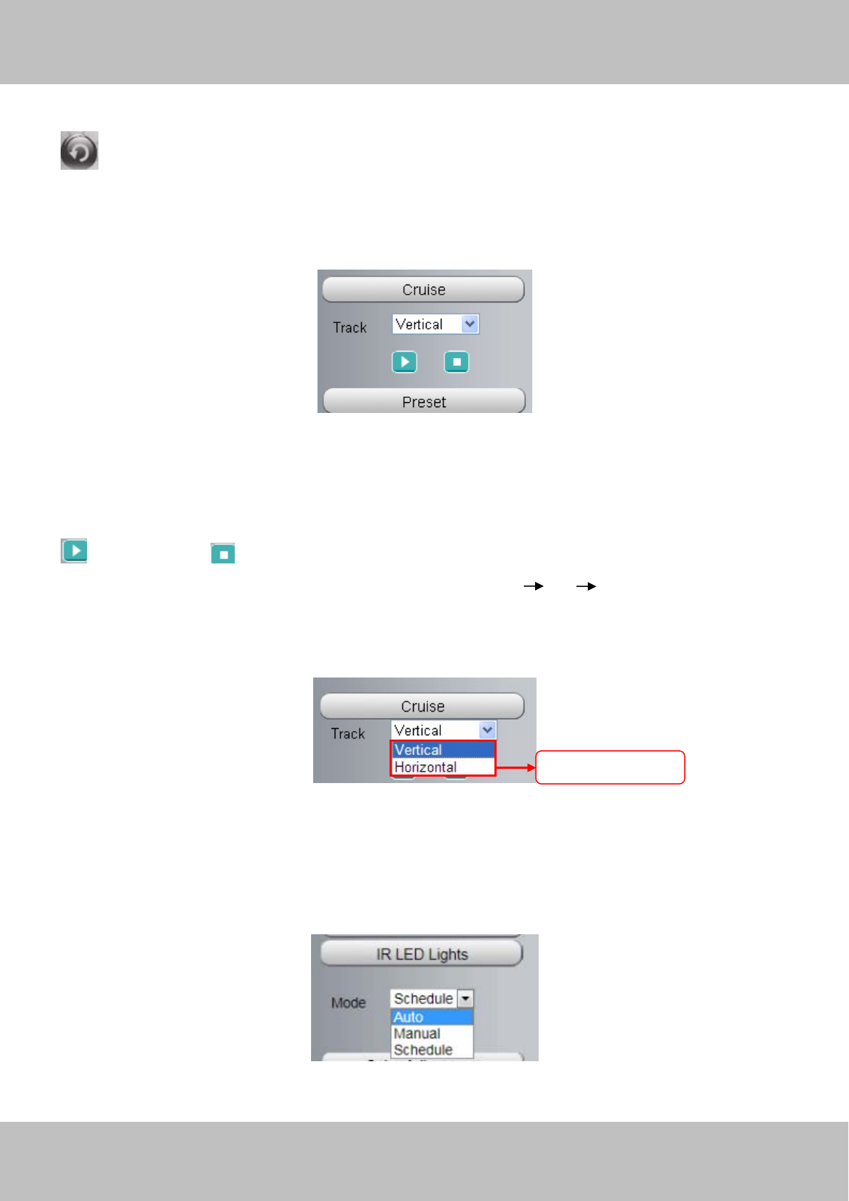
Section5 Cruise settings ( only F9805E)
If via RS485 interface to connect an external PT device, you can use this feature.
The default cruise tracks have two types: Vertical and Horizontal.
Vertical: The camera will rotate from up to down.
Horizontal: The camera will rotate from left to right.
: Start cruise. : Stop cruise.
If you want to define or change the cruise trace, please go to Settings PTZ Preset Settings panel.
How to do cruise?
Firstly: Select one track in the track drop-down list
Secondly: Click Start cruise button, the camera will cruise following the predefined path.
Thirdly: Click stop button and finish cruising.
Section6 IR LED Lights
Click Infra led and there are three modes to adjust the infrared led: Auto, Manual and Schedule.
Select one of these
w
ww
ww
w.
.f
fo
os
sc
ca
am
m.
.c
co
om
m
S
Sh
he
en
nz
zh
he
en
n
F
Fo
os
sc
ca
am
m
I
In
nt
te
el
ll
li
ig
ge
en
nt
t
T
Te
ec
ch
hn
no
ol
lo
og
gy
y
C
Co
o.
.,
,
L
Li
im
mi
it
te
ed
d
T
Te
el
l:
:
8
86
6
7
75
55
5
2
26
67
74
4
5
56
66
68
8
F
Fa
ax
x:
:
8
86
6
7
75
55
5
2
26
67
74
4
5
51
16
68
8
27
Auto: Select it and the camera will adjust the infra led (on or off) automatically.
Manual: Select it and turn off the infra led manually.
Schedule: Select it and the IR led light will be off at the schedule period. If you want to define or change the IR
led lights schedule time, please go to Settings→Video→IR LED Schedule page.
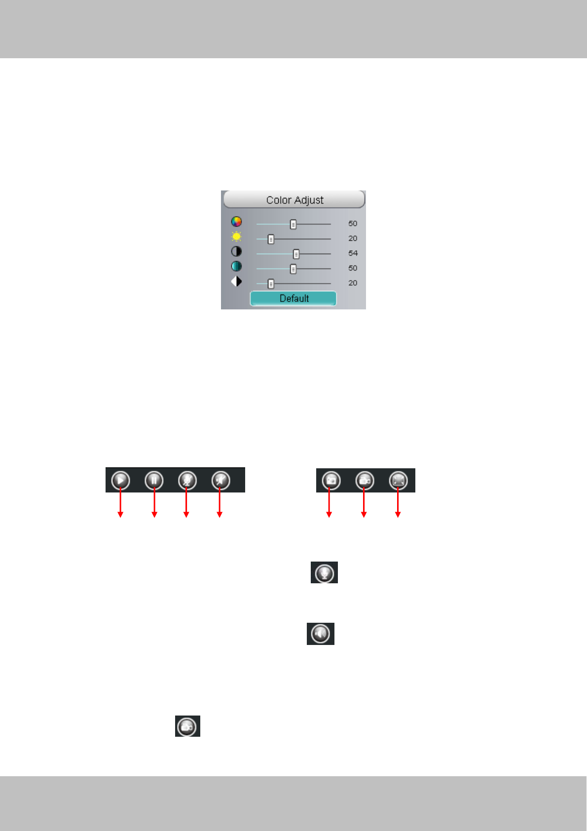
Section7 Image quality settings
In this page, you can tune Hue, Brightness, Contrast, Saturation, and Sharpness to get higher quality.
Section8 OSD
If you have added time and camera name in the video, you can see it in the live window.
Go to Settings ---Basic settings---Camera name panel, and you can change another device name. The
default device name is anonymous.
Go to Settings ---Basic settings---Camera time panel and adjust the device time.
Go to Settings ---Video---On Screen Display panel, you can add or no add OSD.
Section9 Play/Stop/ Talk/Audio/ Snap/ Record/ Full screen button
1------Play Click it to play the video of the camera
2------Stop Click it to stop the video of the camera
3------ Talk: Click the button and the icon will become to , then talk to the microphone that connected
with PC, people around the camera can hear your voice if the camera has connected with audio output device.
Click the icon again and stop talking.
4------ Audio Click the button and the icon will become to , you can hear the sound around the camera if
the camera has connected with other audio input device through the Audio Input port of the camera, Click the
icon again and stop audio.
5----- Snap: Click it to make snapshot and it pop up a window which picture you snapshot, right click in the
window and save the picture to anywhere you want.
6----- Record: Click the icon and the camera start recording, you can see a green dot in the live window.
Click again and stop recording. The default storage path is C:\IPCamRecord. You can change the storage path:
Go to Settings- >Record-> Storage Location panel.
1 2 3 567
4
w
ww
ww
w.
.f
fo
os
sc
ca
am
m.
.c
co
om
m
S
Sh
he
en
nz
zh
he
en
n
F
Fo
os
sc
ca
am
m
I
In
nt
te
el
ll
li
ig
ge
en
nt
t
T
Te
ec
ch
hn
no
ol
lo
og
gy
y
C
Co
o.
.,
,
L
Li
im
mi
it
te
ed
d
T
Te
el
l:
:
8
86
6
7
75
55
5
2
26
67
74
4
5
56
66
68
8
F
Fa
ax
x:
:
8
86
6
7
75
55
5
2
26
67
74
4
5
51
16
68
8
28
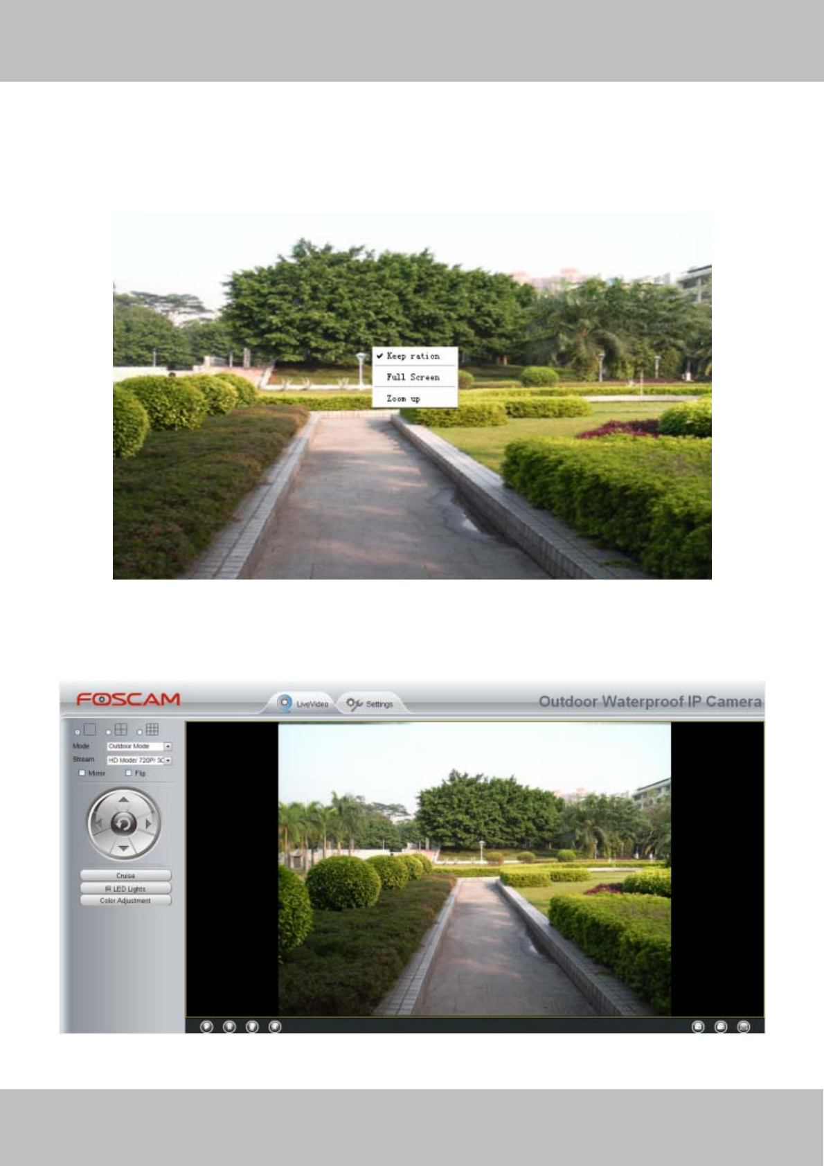
7------Full Screen Click it to make full-screen, or you can double click the surveillance screen to make
full-screen. Double click again and exit full-screen.
Onscreen Mouse Control
Right click the mouse and you can adjust the screen ration, full screen and Zoom up.
Figure 3.11
Keep ration: Select it and the camera will adjust the size of live window based on the computer monitor
automatically.
Sometimes there is a black border around the video, please select Keep ration to get a better visual quality.
Figure 3.12

w
ww
ww
w.
.f
fo
os
sc
ca
am
m.
.c
co
om
m
S
Sh
he
en
nz
zh
he
en
n
F
Fo
os
sc
ca
am
m
I
In
nt
te
el
ll
li
ig
ge
en
nt
t
T
Te
ec
ch
hn
no
ol
lo
og
gy
y
C
Co
o.
.,
,
L
Li
im
mi
it
te
ed
d
T
Te
el
l:
:
8
86
6
7
75
55
5
2
26
67
74
4
5
56
66
68
8
F
Fa
ax
x:
:
8
86
6
7
75
55
5
2
26
67
74
4
5
51
16
68
8
29
Full Screen: Select it and Click it to make full-screen, press ESC and exit full-screen.
Zoom up/down: Click it and the live view will be digital zoomed up, then click Zoom Down and the live view
back to original size.
Figure 3.13
NOTES:
1 This camera don’t support Pan/Tilt function, so here cann’t allow to use Screen PTZ.
2 For Mac OS, the plugin cannot support Onscreen Mouse function, so you cannot allow to use it.
w
ww
ww
w.
.f
fo
os
sc
ca
am
m.
.c
co
om
m
S
Sh
he
en
nz
zh
he
en
n
F
Fo
os
sc
ca
am
m
I
In
nt
te
el
ll
li
ig
ge
en
nt
t
T
Te
ec
ch
hn
no
ol
lo
og
gy
y
C
Co
o.
.,
,
L
Li
im
mi
it
te
ed
d
T
Te
el
l:
:
8
86
6
7
75
55
5
2
26
67
74
4
5
56
66
68
8
F
Fa
ax
x:
:
8
86
6
7
75
55
5
2
26
67
74
4
5
51
16
68
8
30
4 Advanced Camera Settings
Click the button “Settings”, goes to Administrator Control Panel to make advanced camera settings.
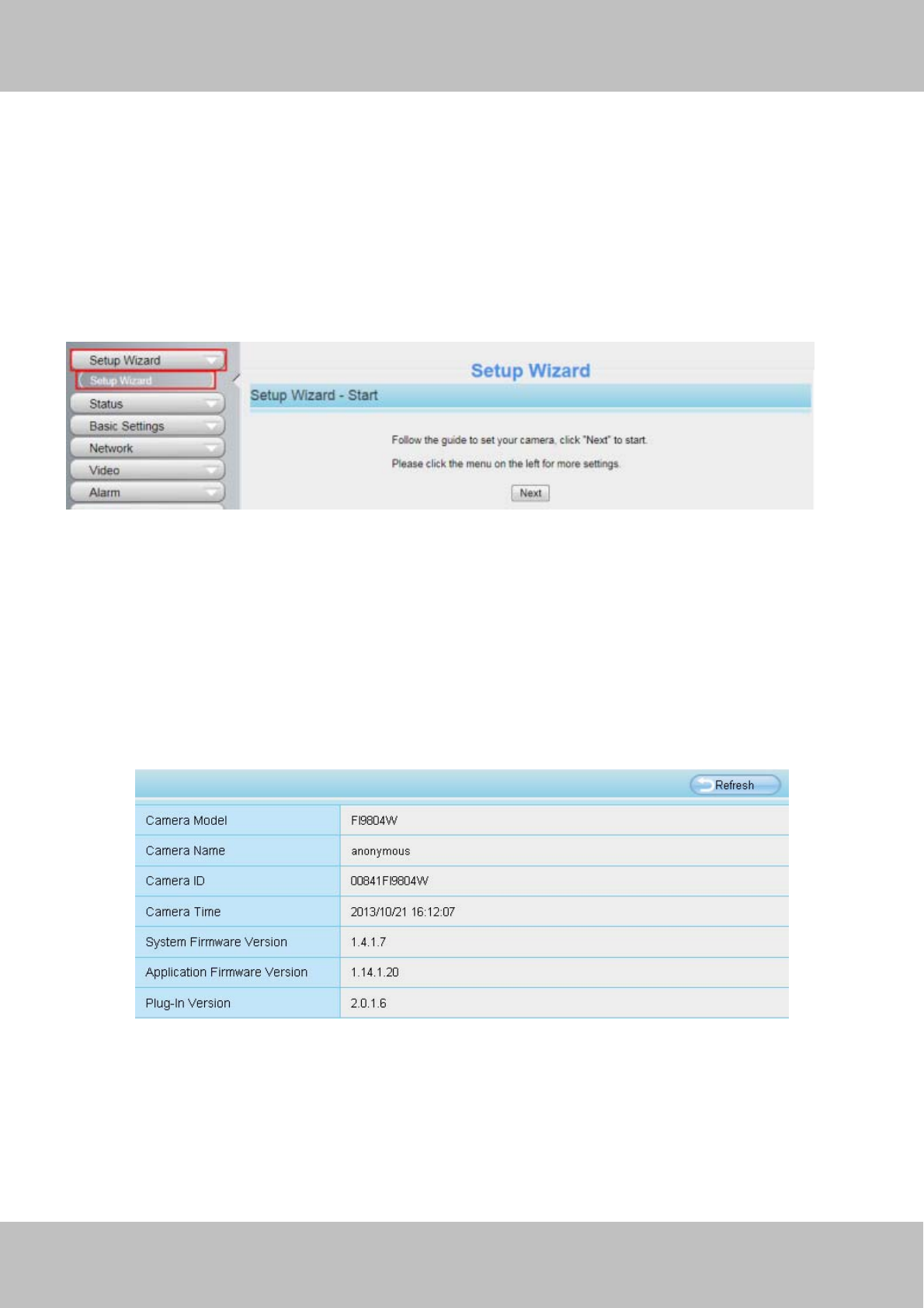
4.1 Setup Wizard
The way to set it,you could refer to section 3.1.
Figure 4.1
4.2 Device Status
Device Status contains four columns: Device Information, Device Status, Session Status and Log, it will show
you various information about your camera.
4.2.1 Device Information
Figure 4.2
Camera Model: The model of the device.
Camera Name: The Device Name is a unique name that you can give to your device to help you identify it.
Click Basic Settings and go to Device Name panel where you can change your camera name. The default
device name is anonymous.
Camera ID: Display the MAC address of your camera. For example Device ID is 008414350787, the same
w
ww
ww
w.
.f
fo
os
sc
ca
am
m.
.c
co
om
m
S
Sh
he
en
nz
zh
he
en
n
F
Fo
os
sc
ca
am
m
I
In
nt
te
el
ll
li
ig
ge
en
nt
t
T
Te
ec
ch
hn
no
ol
lo
og
gy
y
C
Co
o.
.,
,
L
Li
im
mi
it
te
ed
d
T
Te
el
l:
:
8
86
6
7
75
55
5
2
26
67
74
4
5
56
66
68
8
F
Fa
ax
x:
:
8
86
6
7
75
55
5
2
26
67
74
4
5
51
16
68
8
31
MAC ID sticker is found at the bottom of the camera.
Camera Time: The system time of the device. Click Basic Settings and go to Camera Time panel and adjust
the time.
System Firmware Version: Display the System Firmware version of your camera.
Application Firmware Version: Display the application firmware version of your camera.
Plug-In Version: Display the plug-in version of your camera
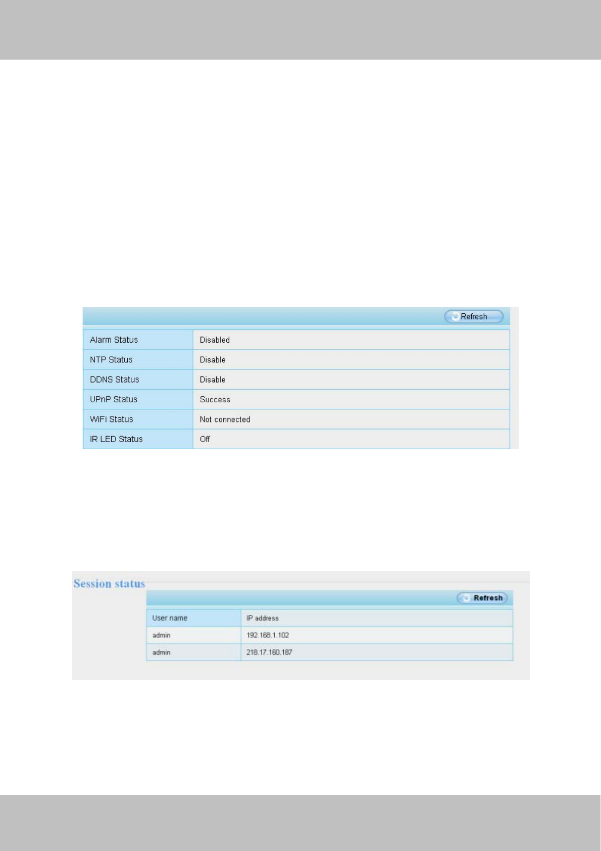
4.2.2 Device Status
On this page you can see device status such as Alarm status, NTP/DDNS status, WIFI status and so on.
Figure 4.3
4.2.3 Session status
Session status will display who and which IP is visiting the camera now.
Figure 4.4
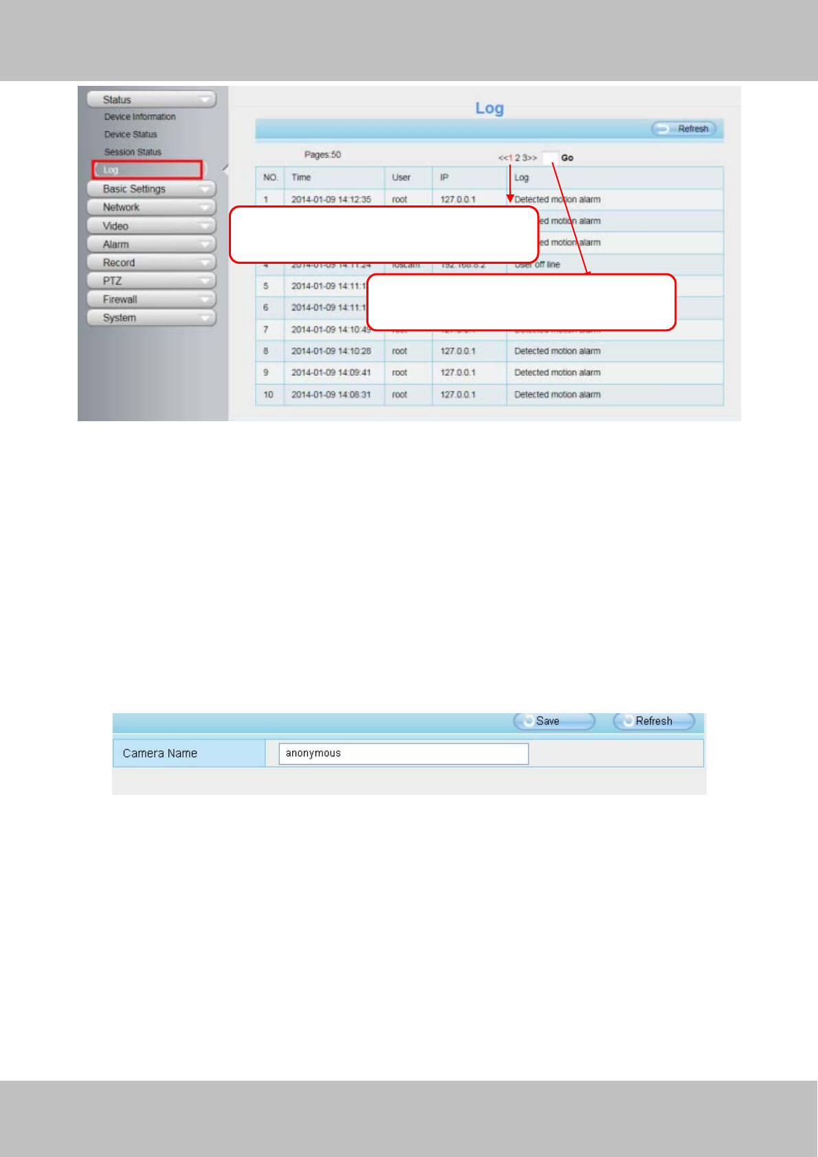
4.2.4 Log
The log record shows who and which IP address accessed or logout the camera and when.
w
ww
ww
w.
.f
fo
os
sc
ca
am
m.
.c
co
om
m
S
Sh
he
en
nz
zh
he
en
n
F
Fo
os
sc
ca
am
m
I
In
nt
te
el
ll
li
ig
ge
en
nt
t
T
Te
ec
ch
hn
no
ol
lo
og
gy
y
C
Co
o.
.,
,
L
Li
im
mi
it
te
ed
d
T
Te
el
l:
:
8
86
6
7
75
55
5
2
26
67
74
4
5
56
66
68
8
F
Fa
ax
x:
:
8
86
6
7
75
55
5
2
26
67
74
4
5
51
16
68
8
32
Figure 4.5
Reboot the camera and clear the log records.
4.3 Basic Settings
This section allows you to configure your Camera Name, Camera Time, Mail, User Accounts and Multi-Device.
4.3.1 Camera Name
Default alias is anonymous. You can define a name for your camera here such as apple. Click Save to save
your changes. The alias name cannot contain special characters.
Figure 4.6
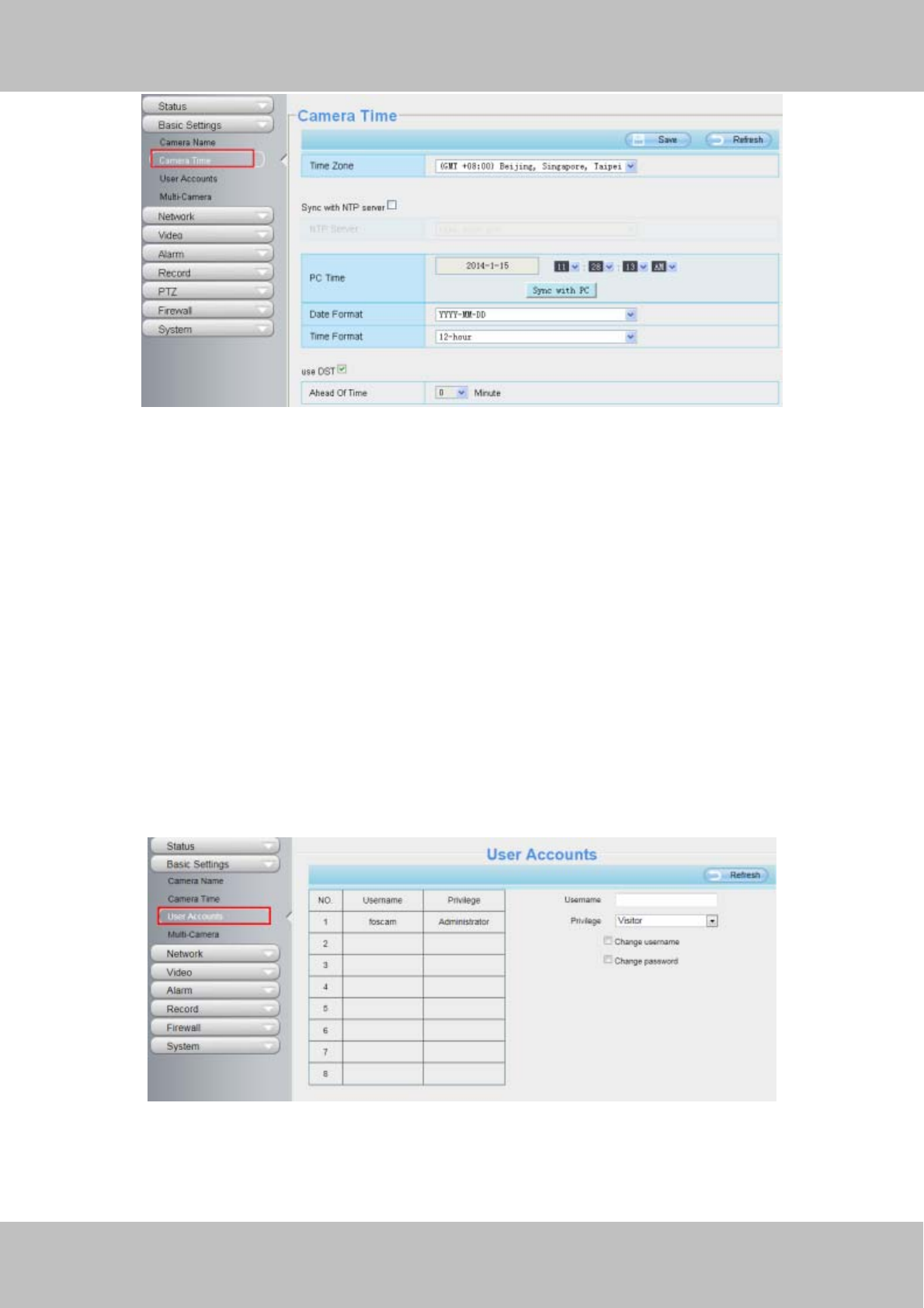
4.3.2 Camera Time
This section allows you to configure the settings of the internal system clocks for your camera.
Click the page number and go to the
corres
p
ondin
g
p
a
g
e to see more lo
g
s.
Fill in one page number, click Go button
and
g
o to the corres
p
ondin
g
p
a
g
e .
w
ww
ww
w.
.f
fo
os
sc
ca
am
m.
.c
co
om
m
S
Sh
he
en
nz
zh
he
en
n
F
Fo
os
sc
ca
am
m
I
In
nt
te
el
ll
li
ig
ge
en
nt
t
T
Te
ec
ch
hn
no
ol
lo
og
gy
y
C
Co
o.
.,
,
L
Li
im
mi
it
te
ed
d
T
Te
el
l:
:
8
86
6
7
75
55
5
2
26
67
74
4
5
56
66
68
8
F
Fa
ax
x:
:
8
86
6
7
75
55
5
2
26
67
74
4
5
51
16
68
8
33
Figure 4.7
Time Zone: Select the time zone for your region from the drop-down menu.
Sync with NTP server: Network Time Protocol will synchronize your camera with an Internet time server.
Choose the one that is closest to your camera.
Sync with PC: Select this option to synchronize the date and time of the Network Camera with your computer.
Manually: The administrator can enter the date and time manually. Please select the date and time format.
use DST: Select the use DST, then select the daylight saving time from the drop-down menu.
Click Save button to submit your settings.
NOTE: If the power supply of camera is disconnect, you need set the camera’s time again.
4.3.3 User Accounts
Here you can create users and set privilege, visitor, operator or administrator. The default administrator
user accounts are admin with a blank password.
Figure 4.8
How to change the password?
Firstly, select the account which you want to change the password, then select “Change password”, enter the
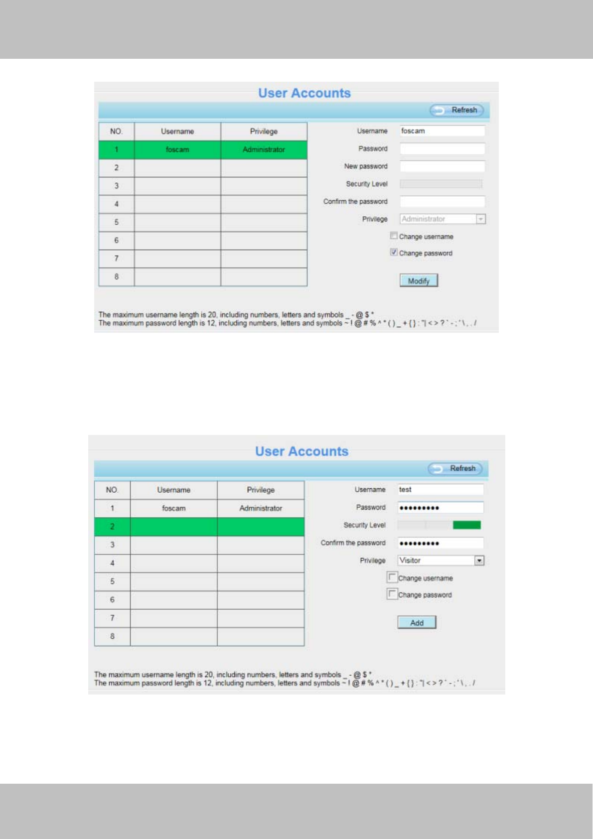
w
ww
ww
w.
.f
fo
os
sc
ca
am
m.
.c
co
om
m
S
Sh
he
en
nz
zh
he
en
n
F
Fo
os
sc
ca
am
m
I
In
nt
te
el
ll
li
ig
ge
en
nt
t
T
Te
ec
ch
hn
no
ol
lo
og
gy
y
C
Co
o.
.,
,
L
Li
im
mi
it
te
ed
d
T
Te
el
l:
:
8
86
6
7
75
55
5
2
26
67
74
4
5
56
66
68
8
F
Fa
ax
x:
:
8
86
6
7
75
55
5
2
26
67
74
4
5
51
16
68
8
34
old password and the new password, lastly click modify to take effect.
Figure 4.9
How to add account ?
Select one blank column, then enter the new user name, password and privilege, last click Add to take effect.
You can see the new added account on the Account list.
Figure 4.10
w
ww
ww
w.
.f
fo
os
sc
ca
am
m.
.c
co
om
m
S
Sh
he
en
nz
zh
he
en
n
F
Fo
os
sc
ca
am
m
I
In
nt
te
el
ll
li
ig
ge
en
nt
t
T
Te
ec
ch
hn
no
ol
lo
og
gy
y
C
Co
o.
.,
,
L
Li
im
mi
it
te
ed
d
T
Te
el
l:
:
8
86
6
7
75
55
5
2
26
67
74
4
5
56
66
68
8
F
Fa
ax
x:
:
8
86
6
7
75
55
5
2
26
67
74
4
5
51
16
68
8
35
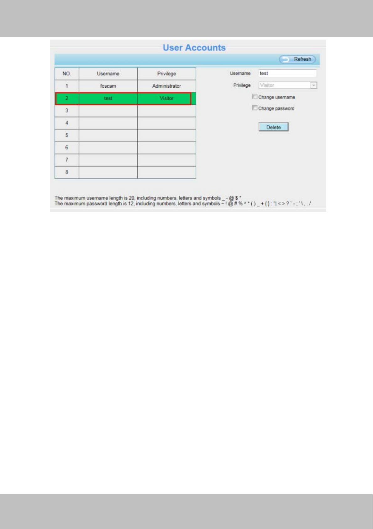
Figure 4.11
Delete: Select the account which you want to delete, then click Delete button to take effect.
NOTE:
The default administrator account cannot be deleted, but you can add other administrator users.
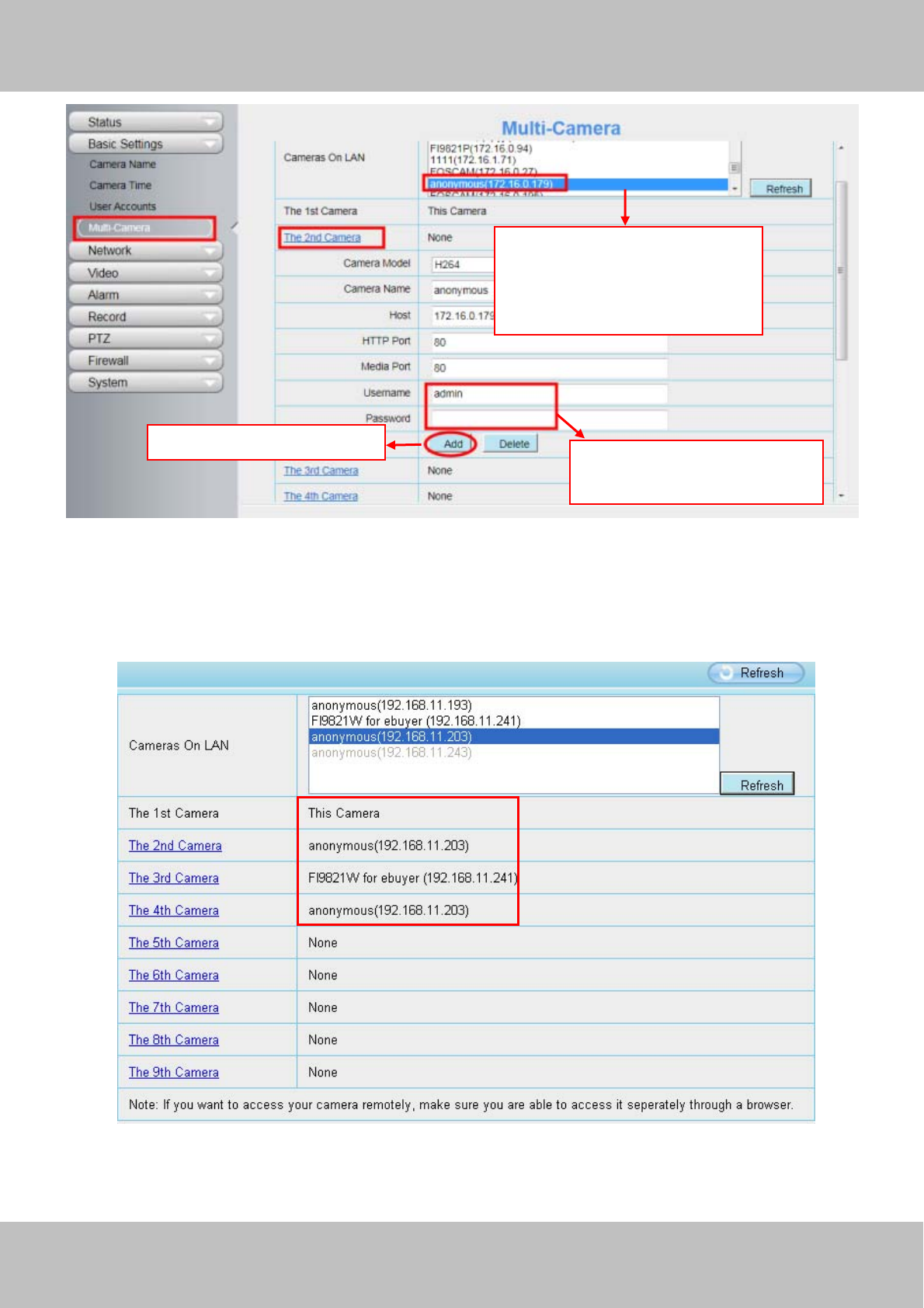
4.3.4 Multi-Camera
If you want to view multi-surveillance screens on one window, you need to login one camera, and set it as the
main device, and do Multi-Device Settings, add other cameras to the first one camera. Before you do
multi-cams settings, you need to assign different port such as 81, 82, 83, 84, 85, 86, 87, 88 to the cameras if
there is 8 cams installed.
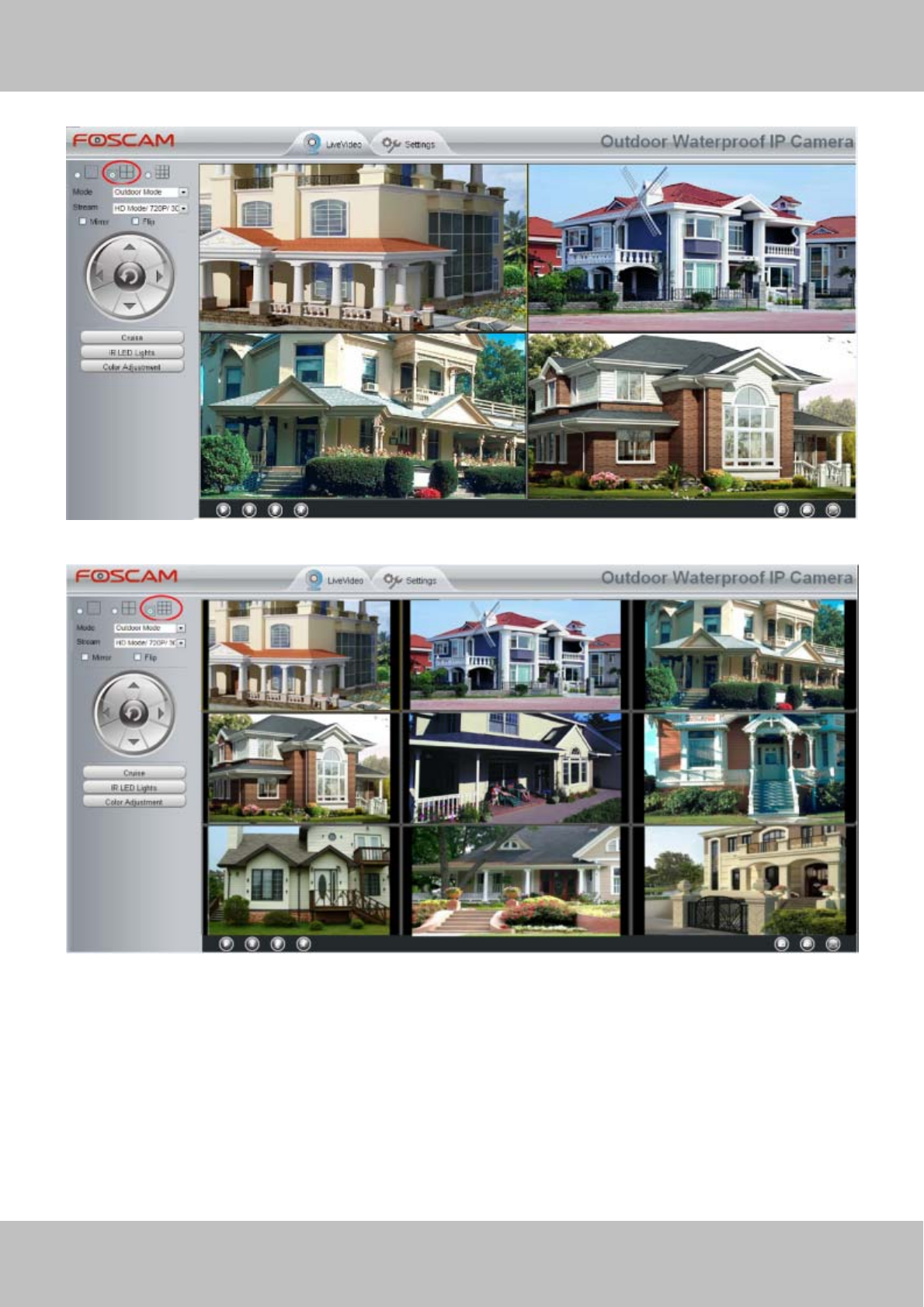
The firmware within the camera can support a maximum of 9 devices monitoring all at the same time. This
page you can both add FOSCAM MJPEG and H.264 series cameras to the first camera and view
multi-surveillance screen on one window.
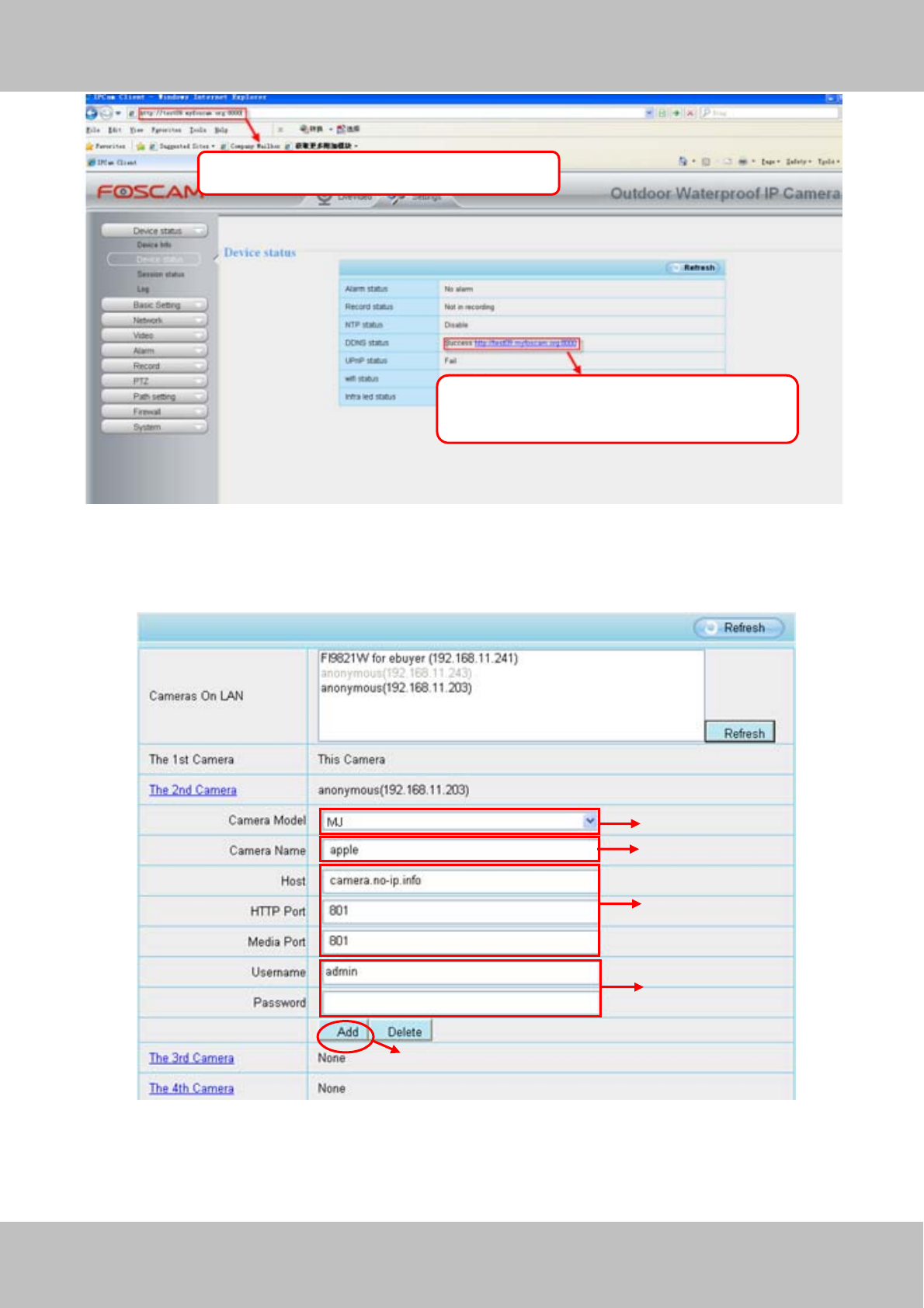
Add cameras in LAN
In Multi-Device Settings page, you can see all devices searched in LAN. The 1st Device is the default one. You
can add more cameras in the list in LAN for monitoring. The camera’s software supports up to 9 IP Cameras
online simultaneously. Click The 2nd Device and click the item in the Device List in LAN, the Alias, Host and
Http Port will be filled in the boxes below automatically. Enter the correct username and password then click
Add. Add more cameras in the same way.
w
ww
ww
w.
.f
fo
os
sc
ca
am
m.
.c
co
om
m
S
Sh
he
en
nz
zh
he
en
n
F
Fo
os
sc
ca
am
m
I
In
nt
te
el
ll
li
ig
ge
en
nt
t
T
Te
ec
ch
hn
no
ol
lo
og
gy
y
C
Co
o.
.,
,
L
Li
im
mi
it
te
ed
d
T
Te
el
l:
:
8
86
6
7
75
55
5
2
26
67
74
4
5
56
66
68
8
F
Fa
ax
x:
:
8
86
6
7
75
55
5
2
26
67
74
4
5
51
16
68
8
36
Figure 4.12
Camera Model: Our Company produces two series cameras: MJPEG and H.264. Here will show you which
series the camera belongs to.
Figure 4.13
Back to Surveillance Windows, and click Four Windows option, you will see four cameras you added.
2 Enter the User name and
password of the 2nd camera .
1 Click it, camera model, alias,
host and HTTP Port will be
filled in the following boxes
automatically .
3 Click Add to take effect .
w
ww
ww
w.
.f
fo
os
sc
ca
am
m.
.c
co
om
m
S
Sh
he
en
nz
zh
he
en
n
F
Fo
os
sc
ca
am
m
I
In
nt
te
el
ll
li
ig
ge
en
nt
t
T
Te
ec
ch
hn
no
ol
lo
og
gy
y
C
Co
o.
.,
,
L
Li
im
mi
it
te
ed
d
T
Te
el
l:
:
8
86
6
7
75
55
5
2
26
67
74
4
5
56
66
68
8
F
Fa
ax
x:
:
8
86
6
7
75
55
5
2
26
67
74
4
5
51
16
68
8
37
Figure 4.14
Figure 4.15
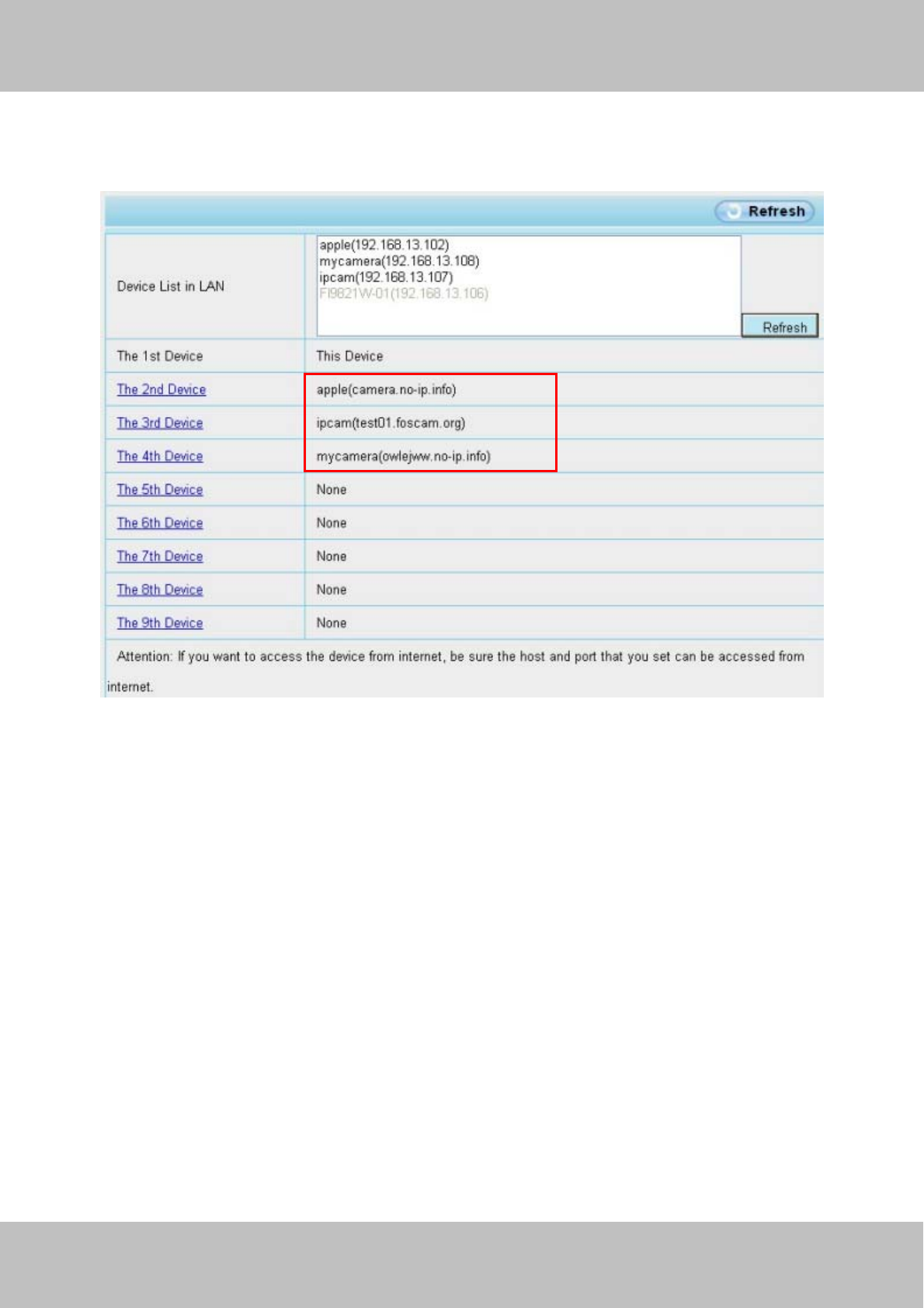
Add cameras in WAN
If you want to view all cameras via the internet(remote computer), you will need to add them using DDNS
domain name. Firstly, make sure all of the cameras you added can be accessed through the internet. (Read
How to configure DDNS settings in chapter 4.4.4)
Login to the first camera using a DDNS domain name and port.
w
ww
ww
w.
.f
fo
os
sc
ca
am
m.
.c
co
om
m
S
Sh
he
en
nz
zh
he
en
n
F
Fo
os
sc
ca
am
m
I
In
nt
te
el
ll
li
ig
ge
en
nt
t
T
Te
ec
ch
hn
no
ol
lo
og
gy
y
C
Co
o.
.,
,
L
Li
im
mi
it
te
ed
d
T
Te
el
l:
:
8
86
6
7
75
55
5
2
26
67
74
4
5
56
66
68
8
F
Fa
ax
x:
:
8
86
6
7
75
55
5
2
26
67
74
4
5
51
16
68
8
38
Figure 4.16
Click Multi-Device Settings. Choose The 2nd Device. Fill in the 2nd camera’s name, DDNS domain name, port
number. Enter user name and password and then choose Add.
Figure 4.17
1----- The camera model: MJ or H264.
2----- The 2nd camera’s name
Use DDNS domain name and port to login .
Make sure each camera you need add
could login with DDNS name and port .
2
3
4
5
1
w
ww
ww
w.
.f
fo
os
sc
ca
am
m.
.c
co
om
m
S
Sh
he
en
nz
zh
he
en
n
F
Fo
os
sc
ca
am
m
I
In
nt
te
el
ll
li
ig
ge
en
nt
t
T
Te
ec
ch
hn
no
ol
lo
og
gy
y
C
Co
o.
.,
,
L
Li
im
mi
it
te
ed
d
T
Te
el
l:
:
8
86
6
7
75
55
5
2
26
67
74
4
5
56
66
68
8
F
Fa
ax
x:
:
8
86
6
7
75
55
5
2
26
67
74
4
5
51
16
68
8
39
3----- Fill in the 2nd camera’s DDNS host not LAN IP
4 ---- Enter the 2nd camera’s user name and password
5---- Click Add button and to take effect
NOTE: Here the Host must be entered as the second camera’s DDNS domain name, not its LAN IP.
Figure 4.18
Return to video window. You will see all of the cameras accessible through the internet.
When you are away from home, you can use the first camera’s DDNS domain name and port to view all the
cameras via internet.
4.4 Network
This section will allow you to configure your camera’s IP, PPOE, DDNS, Wireless Settings, UPnP, Port, Mail
Settings and FTP Settings.
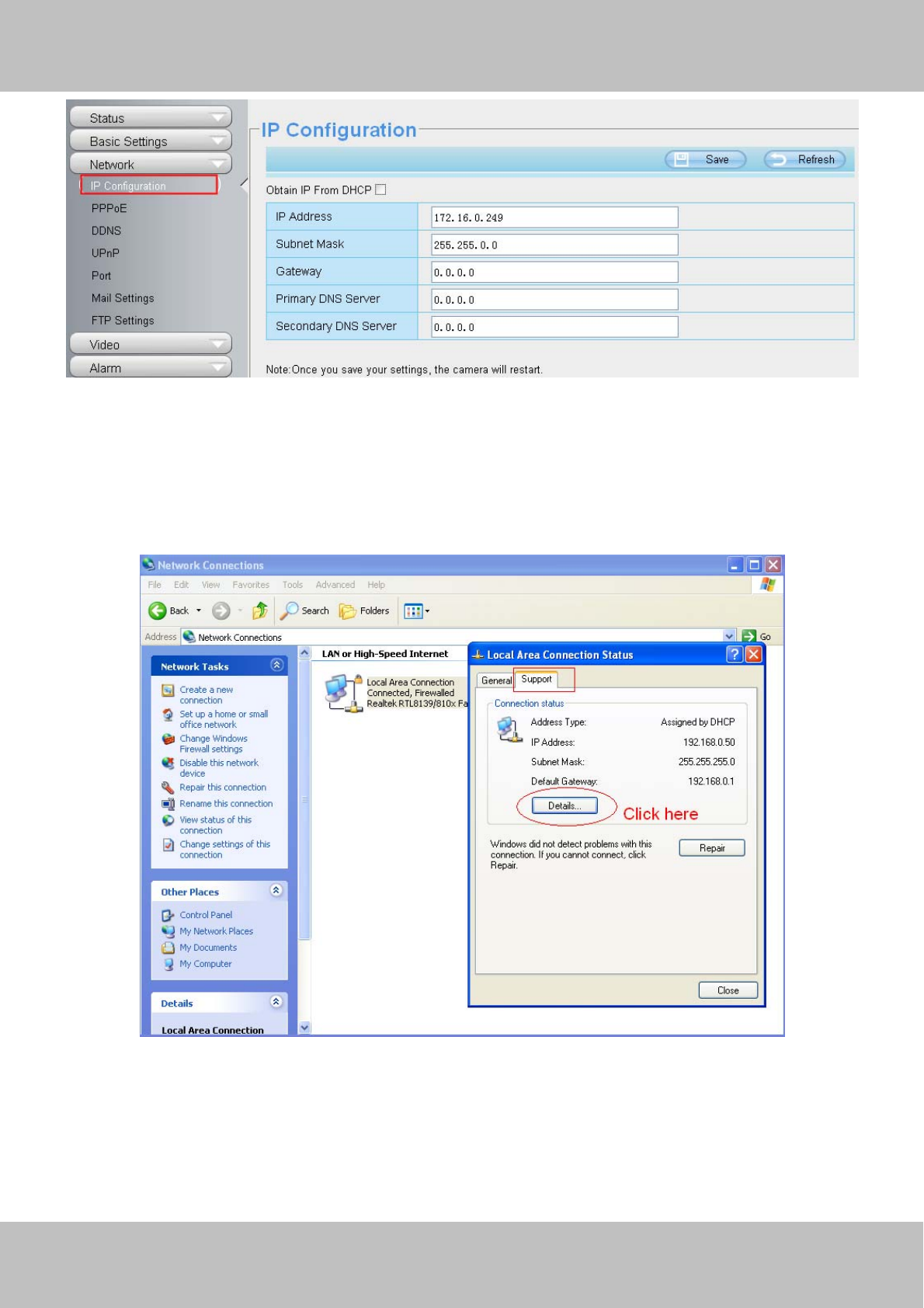
4.4.1 IP Configuration
If you want to set a static IP for the camera, please go to IP Configuration page. Keep the camera in the same
subnet of your router or computer.
w
ww
ww
w.
.f
fo
os
sc
ca
am
m.
.c
co
om
m
S
Sh
he
en
nz
zh
he
en
n
F
Fo
os
sc
ca
am
m
I
In
nt
te
el
ll
li
ig
ge
en
nt
t
T
Te
ec
ch
hn
no
ol
lo
og
gy
y
C
Co
o.
.,
,
L
Li
im
mi
it
te
ed
d
T
Te
el
l:
:
8
86
6
7
75
55
5
2
26
67
74
4
5
56
66
68
8
F
Fa
ax
x:
:
8
86
6
7
75
55
5
2
26
67
74
4
5
51
16
68
8
40
Figure 4.19
Changing settings here is the same as using the IP Camera Tool.
It is recommended that you use the subnet mask, gateway and DNS server from your locally attached PC. If
you don’t know the subnet mask, gateway and DNS server, you can check your computer’s local area
connection as follows:
Control Panel--Network Connections--Local Area Connections --Choose Support--Details.
Figure 4.20

w
ww
ww
w.
.f
fo
os
sc
ca
am
m.
.c
co
om
m
S
Sh
he
en
nz
zh
he
en
n
F
Fo
os
sc
ca
am
m
I
In
nt
te
el
ll
li
ig
ge
en
nt
t
T
Te
ec
ch
hn
no
ol
lo
og
gy
y
C
Co
o.
.,
,
L
Li
im
mi
it
te
ed
d
T
Te
el
l:
:
8
86
6
7
75
55
5
2
26
67
74
4
5
56
66
68
8
F
Fa
ax
x:
:
8
86
6
7
75
55
5
2
26
67
74
4
5
51
16
68
8
41
Figure 4.21
If you don’t know the DNS server, you can use the same settings as the Default Gateway.
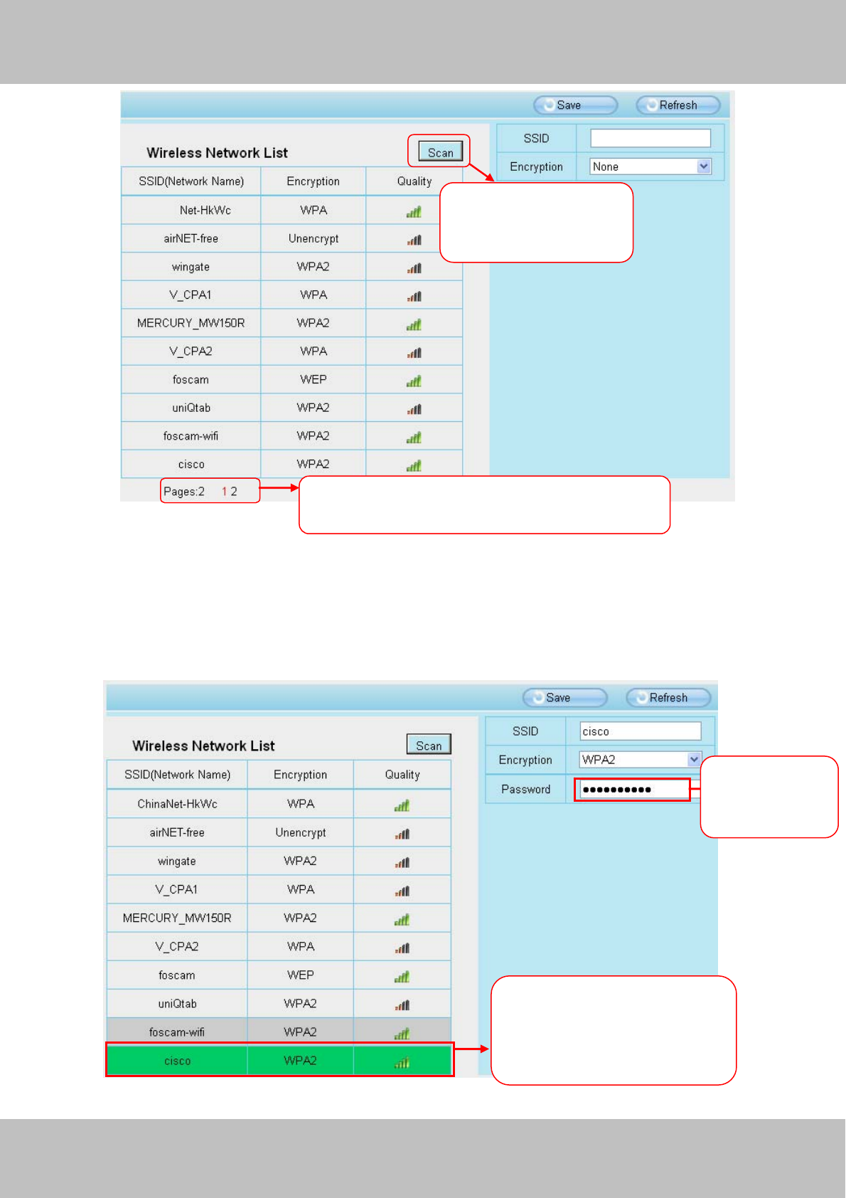
4.4.2 Wireless Settings( FI9803P/FI9804W/FI9805W/FI9900P)
Step 1: Choose “Settings” on the top of the camera interface, and go to the “Network” panel on the left side of
the screen, then click “Wireless Settings.”
Click the Scan button and the camera will detect all wireless networks around the area. It should also display
your router in the list.
Set the same Subnet Mask and
gateway of the camera with your
PC .
There are two DNS servers . You
can set any of them . Same with
gateway is also OK .
w
ww
ww
w.
.f
fo
os
sc
ca
am
m.
.c
co
om
m
S
Sh
he
en
nz
zh
he
en
n
F
Fo
os
sc
ca
am
m
I
In
nt
te
el
ll
li
ig
ge
en
nt
t
T
Te
ec
ch
hn
no
ol
lo
og
gy
y
C
Co
o.
.,
,
L
Li
im
mi
it
te
ed
d
T
Te
el
l:
:
8
86
6
7
75
55
5
2
26
67
74
4
5
56
66
68
8
F
Fa
ax
x:
:
8
86
6
7
75
55
5
2
26
67
74
4
5
51
16
68
8
42
Figure 4.22
Step 2: Click the SSID (name of your router) in the list, the corresponding information related to your network,
such as the name and the encryption, will be filled into the relevant fields automatically.
You will only need to fill in the password of your network. Make sure that the SSID, Encryption and the
password you filled in are exactly the same for your router.
Figure 4.23
Click the Page number to see other wireless
networks devices if there are more than 10.
1 Click the SSID of your router
and the relevant information
will be filled in the fields
automatically.
2 Enter the
password of
y
our router .
Click the Scan button
to search for wireless
networks.
w
ww
ww
w.
.f
fo
os
sc
ca
am
m.
.c
co
om
m
S
Sh
he
en
nz
zh
he
en
n
F
Fo
os
sc
ca
am
m
I
In
nt
te
el
ll
li
ig
ge
en
nt
t
T
Te
ec
ch
hn
no
ol
lo
og
gy
y
C
Co
o.
.,
,
L
Li
im
mi
it
te
ed
d
T
Te
el
l:
:
8
86
6
7
75
55
5
2
26
67
74
4
5
56
66
68
8
F
Fa
ax
x:
:
8
86
6
7
75
55
5
2
26
67
74
4
5
51
16
68
8
43
Step 3: Please click on the Save button after all settings have been entered and disconnect the network cable.
Never shut down the power of the camera until the IP camera is able to connect to the wireless network.
The LAN IP address will disappear on the window of IP Camera Tool when the camera is configuring a wireless
connection. Wait about 1 minute, the camera should obtain a wireless connection, and the LAN IP of the
camera will show again on the window of the IP Camera Tool. The IP address may have changed after the
camera receives a wireless connection; we recommend setting a static local IP address if this IP address
changes by right clicking the camera in IP Camera Tools, setting a static IP, and pushing OK .
Congratulations! You have set up the wireless connection of the camera successfully.
NOTE :
If you fail to make a wireless connection, please refer to your seller or contact us directly for
assistance.
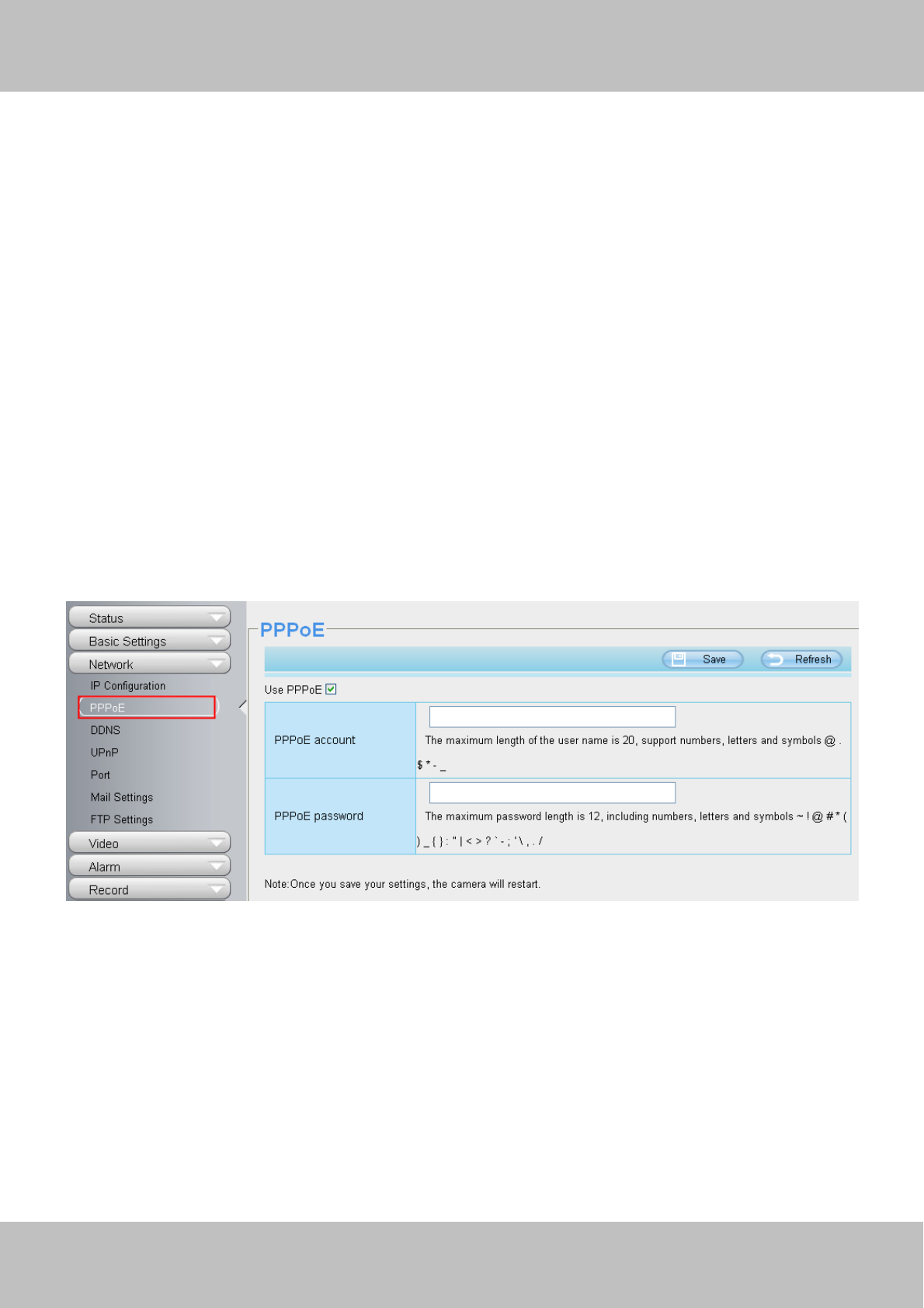
4.4.3 PPPoE
Some models do not support PPPoE.
If you are using a PPPoE connection, enable it and enter the User Name and Password for your PPPoE
account.
Figure 4.24
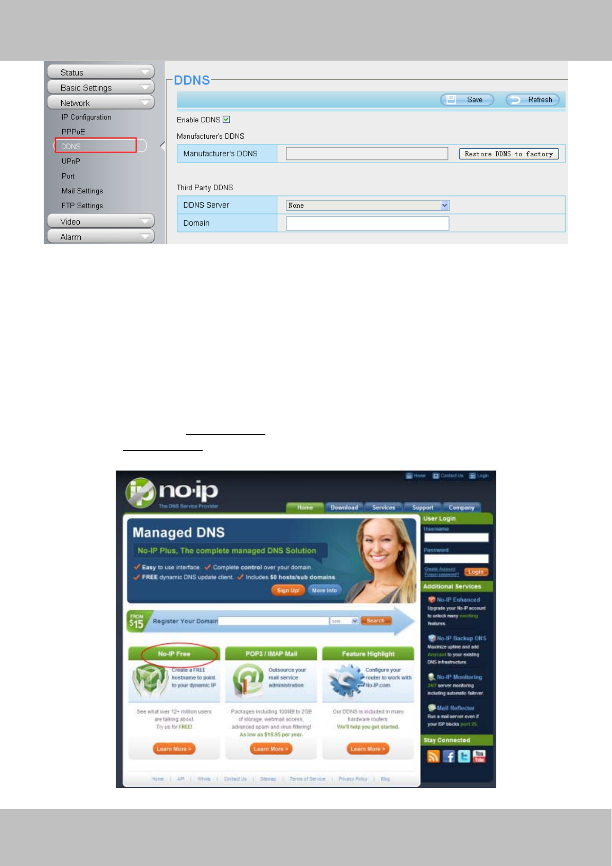
4.4.4 DDNS
FOSCAM camera has embedded a unique DDNS domain name when producing, and you can directly use the
domain name, you can also use the third party domain name.
FOSCAM domain name
Here take cp4911.myfoscam.org for example. Go to option of DDNS on the Settings->Network panel, you
can see the domain name.
w
ww
ww
w.
.f
fo
os
sc
ca
am
m.
.c
co
om
m
S
Sh
he
en
nz
zh
he
en
n
F
Fo
os
sc
ca
am
m
I
In
nt
te
el
ll
li
ig
ge
en
nt
t
T
Te
ec
ch
hn
no
ol
lo
og
gy
y
C
Co
o.
.,
,
L
Li
im
mi
it
te
ed
d
T
Te
el
l:
:
8
86
6
7
75
55
5
2
26
67
74
4
5
56
66
68
8
F
Fa
ax
x:
:
8
86
6
7
75
55
5
2
26
67
74
4
5
51
16
68
8
44
Figure 4.25
Now you can use http:// Domain name + HTTP Port to access the camera via internet.
Take hostname cp4911.myfoscam.org and HTTP Port no. 8000 for example, the accessing link of the camera
via internet would be http://cp4911.myfoscam.org:8000
Restore DDNS to factory: If you have configured Third Party DDNS successfully, but you want to use
Manufacturer’s DDNS again , here click this button and start Manufacturer’s DDNS Service.
Third Party Domain Name Settings
User can also use third part DDNS, such as www.no-ip.com. ,www. 3322.com
Here take www.no-ip.com for example :
①Step 1 Go to the website www.no-ip.com to create a free hostname
Firstly: Login on www.no-ip.com and click No-IP Free to register.
Click here to register

w
ww
ww
w.
.f
fo
os
sc
ca
am
m.
.c
co
om
m
S
Sh
he
en
nz
zh
he
en
n
F
Fo
os
sc
ca
am
m
I
In
nt
te
el
ll
li
ig
ge
en
nt
t
T
Te
ec
ch
hn
no
ol
lo
og
gy
y
C
Co
o.
.,
,
L
Li
im
mi
it
te
ed
d
T
Te
el
l:
:
8
86
6
7
75
55
5
2
26
67
74
4
5
56
66
68
8
F
Fa
ax
x:
:
8
86
6
7
75
55
5
2
26
67
74
4
5
51
16
68
8
45
Figure 4.26
Please register an account step by step according to instructions on www.no-ip.com
After registration, please login your email which used to register. You will receive an email from website, please
click the link to activate your ACCOUNT as indicated in email.
Secondly: Login the link with the registered username and password to create your domain name.
Figure 4.27
Figure 4.28
w
ww
ww
w.
.f
fo
os
sc
ca
am
m.
.c
co
om
m
S
Sh
he
en
nz
zh
he
en
n
F
Fo
os
sc
ca
am
m
I
In
nt
te
el
ll
li
ig
ge
en
nt
t
T
Te
ec
ch
hn
no
ol
lo
og
gy
y
C
Co
o.
.,
,
L
Li
im
mi
it
te
ed
d
T
Te
el
l:
:
8
86
6
7
75
55
5
2
26
67
74
4
5
56
66
68
8
F
Fa
ax
x:
:
8
86
6
7
75
55
5
2
26
67
74
4
5
51
16
68
8
46
Please create the domain name step by step according to instructions on www.no-ip.com
Step 2 DO DDNS Service Settings within the Camera
Please set DDNS Settings within the camera by hostname, a user name and password you’ve got from
www.no-ip.com
Take hostname ycxgwp.no-ip.info, user name foscam, password foscam2012 for example.
Firstly, goes to option of DDNS Settings on the administrator panel.
Secondly, select No-Ip as a server.
Thirdly, fill foscam as DDNS user, fill password foscam2012 as DDNS password, fill ycxgwp.no-ip.info as
DDNS domain and server URL, Then click save to make effect. The camera will restart and to take the DDNS
settings effective.
Fourthly, after the restart, login the camera, and go to option of Device Status on the administrator panel, and
check if the DDNS status is successful.
If failed, please double check if you have input the correct hostname, user name, and password, and try to
redo the settings.
NOTE :
If you have set Third Party DDNS successfully ,the Foscam Domain Name will be invalid. The Third Party
DDNS and the Foscam Domain Name cannot work at the same time, the last time you configured will take
effect.
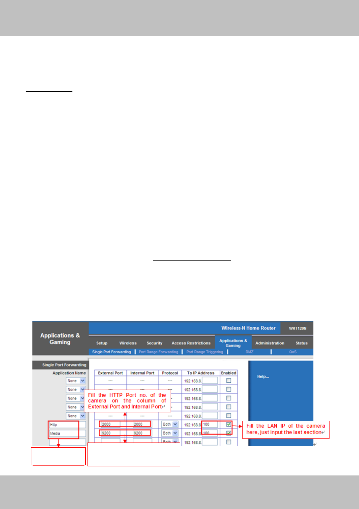
D②o port forwarding within the router
Example: The camera’s LAN IP address is http://192.168.8.100:2000
Firstly, login the router, goes to the menu of Port Forwarding or Port Trigger (or named Virtue
Server on some brands of router). Take Linksys brand router as an example, Login the router, and goes to
Applications & Gaming->Single Port Forwarding.
Secondly, Create a new column by LAN IP address & HTTP Port No. of the camera within the router showed
as below.
Assign a name
as you like here .
Fill the Media Port no. of the
camera on the column of
External Port and Internal Port .
w
ww
ww
w.
.f
fo
os
sc
ca
am
m.
.c
co
om
m
S
Sh
he
en
nz
zh
he
en
n
F
Fo
os
sc
ca
am
m
I
In
nt
te
el
ll
li
ig
ge
en
nt
t
T
Te
ec
ch
hn
no
ol
lo
og
gy
y
C
Co
o.
.,
,
L
Li
im
mi
it
te
ed
d
T
Te
el
l:
:
8
86
6
7
75
55
5
2
26
67
74
4
5
56
66
68
8
F
Fa
ax
x:
:
8
86
6
7
75
55
5
2
26
67
74
4
5
51
16
68
8
47
Figure 4.29
③Use domain name to access the camera via internet
After the port forwarding is finished, you can use the domain name+ http no. to access the camera via
internet. Take hostname ycxgwp.no-ip.info and http no. 2000for example, the accessing link of the camera via
internet would be http:// ycxgwp.no-ip.info:2000
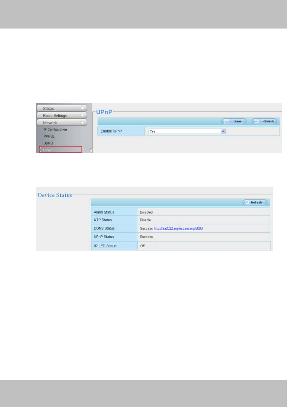
4.4.5 UPnP
Figure 4.30
The default UPnP status is closed. You can enable UPnP, then the camera’s software will be configured for
port forwarding. Back to the “Device Status” panel, you can see the UPnP status:
Figure 4.31
The camera’s software will be configured for port forwarding. There may be issues with your routers security
settings, and sometimes may error. We recommend you configure port forwarding manually on your router .
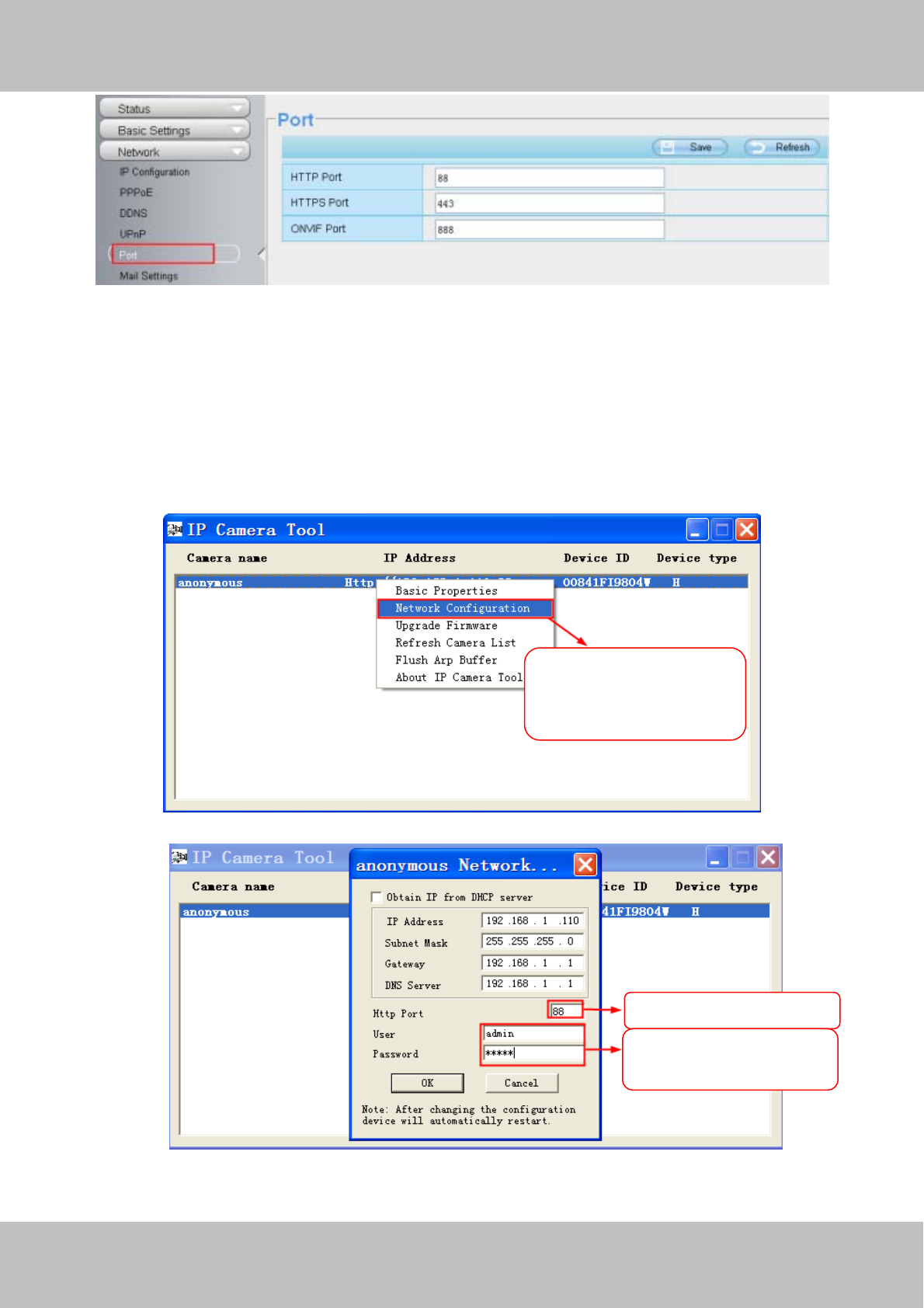
4.4.6 Port
This camera supports HTTP Port / HTTPS Port/ ONVIF Port. HTTP Port is used to access the camera
remotely.
HTTP port : By default, the HTTP is set to 88. Also, they can be assigned with another port number between 1
and 65535. But make sure they can not be conflict with other existing ports like 25, 21.
w
ww
ww
w.
.f
fo
os
sc
ca
am
m.
.c
co
om
m
S
Sh
he
en
nz
zh
he
en
n
F
Fo
os
sc
ca
am
m
I
In
nt
te
el
ll
li
ig
ge
en
nt
t
T
Te
ec
ch
hn
no
ol
lo
og
gy
y
C
Co
o.
.,
,
L
Li
im
mi
it
te
ed
d
T
Te
el
l:
:
8
86
6
7
75
55
5
2
26
67
74
4
5
56
66
68
8
F
Fa
ax
x:
:
8
86
6
7
75
55
5
2
26
67
74
4
5
51
16
68
8
48
Figure 4.32
Another way to change the HTTP port no.
Step 1: Open the IP Camera Tool, select the camera you would like to change the port of, right click on the IP
address, and click on ”Network Configuration”, this brings up the network configuration box as shown in Figure
4.34 and 4.35.
Figure 4.33
Figure 4.34
Step 2: Enter the username and password of the Administrator (default username is admin with a blank
Select which camera
you’d like to change the
port for, and right click .
Modif
y
the Http Port .
Enter the Username and
p
assword
,
click O
K
.