Shinko Electric Co 199909010001 Communication Modem Controller User Manual System Operation Manual
Shinko Electric Co Ltd Communication Modem Controller System Operation Manual
Contents
System Operation Manual
FCC ID : OPO199909010001
KEN72-3696
1
CONFIDENTIAL
“SELOHT SOHT-300”
SYSTEM OPERATION MANUAL
of
SHINKO OHT SYSTEM
FCC ID : OPO199909010001
KEN72-3696
2
Table of contents
SAFETY PRECAUTIONS...............................................................................................................................................3
1.GENERAL......................................................................................................................................................................7
1.1 APPLICATION ............................................................................................................................................................7
1.2 RELATED SEMI DOCUMENT .....................................................................................................................................7
1.3 RELATED RULES, LAWS............................................................................................................................................7
1.4 ABBREVIATIONS........................................................................................................................................................7
2. OUTLINE OF OHT SYSTEM.....................................................................................................................................8
2.1 CONSTRUCTION OF OHT SYSTEM .............................................................................................................................9
2.2 NON-CONTACT POWER SUPPLY ...............................................................................................................................11
2.3 FCC RULES.............................................................................................................................................................12
3 SPECIFICATION........................................................................................................................................................14
3.1 GENERAL CONDITION ......................................................................................................................................14
3.2 SYSTEM COMPONENT AND CONSTRUCTION.............................................................................................................18
4. TRANSPORTATION CONTROL............................................................................................................................23
5. ERROR HANDLING .................................................................................................................................................24
5.1 GENERAL ................................................................................................................................................................24
5.2 ERROR HANDLING ...................................................................................................................................................25
5.3 RECOVERY PROCEDURE IN CASE OF HEAVY ERROR OF A VEHICLE ..........................................................................28
6. RELATED DOCUMENTS.........................................................................................................................................29

FCC ID : OPO199909010001
KEN72-3696
3
Safety precautions
(1) General
Prior to using this product, make sure the “Safety Precautions”, Maintenance
Instruction Manual and other attached documents shall be well read and understood
for appropriate application.
Engage specialists in electrical works.
Don’t improve the product by yourselves.
Be sufficiently proficient with the equipment, the relevant safety knowledge and the
precautions prior to using this product.
In the content of this “Safety Precautions”, items which need to be cautions of out shall
be classified into “Danger” and “Warning”.
(2) Definitions of Danger and Warning
[Note 1] Medium degree of injuries or light injuries refers to injuries, e.g., burns
and
electric shock, which do not require hospitalization of or prolonged hospital
visit by the victims. As material losses refers to expanded losses pertaining to
the
damage of property and equipment.
Note that, depending on the situation, the events described under “Warning” may also
result in severe outcome. In either case, make sure that the advice is followed.
After reading, make sure this information shall be kept at places where it can always be
read by users.

FCC ID : OPO199909010001
KEN72-3696
4
(3) Precautions on use
Danger
Follow the following advice strictly to avoid electric shock or burns.
1. Don’t enter the operation area of the vehicle.
Work on the ladder may collide to the vehicle and may cause injury.
2. Don’t touch the vehicle on the track when Power Supply Panel output the
power.
3. Don’t touch the moving parts of the vehicle while it is in operation. Doing
so may cause injuries.
4. Don’t touch and Teaching and maintenance shall be done by a qualified person.
5. Make sure the earth terminals for the relate equipment shall be grounded.
Not doing so may cause electric shock.
6. Don’t break the cable, impose excessive stress, place heavy weights, or
pinch it between items. Doing so may cause electric shock.
Warning
Don’t use the equipment at locations where water, corrosive atmosphere, or
flammable gas is present, or beside flammable items. Doing so may cause
life and fails.

FCC ID : OPO199909010001
KEN72-3696
5
(4) Storage
Prohibition
1. Don’t store the equipment at locations where it is subject to rain, water
hazardous gas or liquid.
Mandatory Implementation
1. Store the equipment at locations in not subjected to sun shine. Store it
at predetermined relative humidity and temperature.
0 50 ,90% RH and below, no dew.
(5) Transportation
Warning
1. Don’t carry in a manner except for designated. Doing so may cause materiales
loss or injuries.
Mandatory Implementation
1. The equipment may be broken when overloaded. Follow the advice of the
display on the load.
(6) Installation
Warning
1. Don’t climb on top of the equipment or place heavy items on it. Doing so
may cause injuries.
2. Don’t block the air inlet and outlet ports or allow foreign particles to enter them.
Doing so may cause fire.
3. Follow the installation direction strictly as it is so design for dissipation of heat.
fails or fire.
5. Don’t hit the equipment with strong impact. Doing so may cause equipment
fails.
(7) Operations

FCC ID : OPO199909010001
KEN72-3696
6
Mandatory Implementation
Install an external emergency circuit so that operations can be immediately stopped
and power cut off when required
(8) Maintenance and lnspection
Prohibition
Don’t engage non-specialist technicians to disassemble and repair the
equipment.
Danger
1. Maintenance of the vehicle shall be done on the ground.
2. Switch off the power and wait for 3 minutes or longer before carrying out
wiring work or inspection. Not doing so may cause electric shock.
(The printed circuit board in the driver applies 300V of high voltage parts)
FCC ID : OPO199909010001
KEN72-3696
7
1.General
1.1 Application
This document describes the operation of OHT Vehicle for “SELOHT SOHT-300”,
Shinko OHT(Overhead Hoist Transport) System.
1.2 Related SEMI document
Following documents are parts of the specification:
(1) SEMI E10-0299 (1999) (RAM)
(2) SEMI E15.1-0299 (1999) (LOAD PORT)
(3) SEMI E30-0998 (1998) (GEM)
(4) SEMI Draft 2998 (Future E82-0999 (1999), IBSEM)
(5) SEMI E37.1-96 (1996) (HSMS-SS)
(6) SEMI E47.1-0299 (1999) (FOUP)
(7) SEMI E84-0699 (1999) (Extended P I/O)
1.3 Related Rules, Laws
(1) FCC Part15 Subpart C
(2) FCC Part 18
1.4 Abbreviations
(1) OHT : Overhead Hoist Transport
(2) OHV : Overhead Hoist transport Vehicle
(3) OHVC : Overhead Hoist Vehicle Controller
(4) CMC : Communication Modem Controller
FCC ID : OPO199909010001
KEN72-3696 8
2. Outline of OHT System
Fig. 2.1 System Construction
FCC ID : OPO199909010001
KEN72-3696
9
2.1 Construction of OHT system
Fig.2.1 shows a typical construction oh Shinko OHT system.
As shown in the Fig. , Shinko OHT system is composed from the equipment listed
below.
OHT Vehicle
OHT Track
Power Supply Panel
Maintenance Shifter/lifter,
OHVC
Process tool (Stocker)
FOUP, etc.
(1)OHT Vehicle
Main device of the system is an OHT Vehicle, which is hung from the OHT track and
travels through the track. OHV has a hoisting mechanism and a FOUP is hoisted
down/up to the port of the process tool.
(2)OHT Track
OHT track is supported from the building ceiling, and OHV is hung from the track.
OHV travels by the linear motor power and the electricity is supplied from the track side
by non-contact power supply system.
(3)Power Supply Panel
Power Supply Panel is composed from three portion.
(a) Power distribution Panel portion
Power source of the facility in the voltage of 208V is connected to the distribution Panel
of the Power Supply Panel. And from hear, electric power is distributed to the OHT
system components (i.e. Power supply portion of this panel, Maintenance shifter/lifter,
OHVC. OHVC is operated in A.C.120 V, so voltage is transformed from 208V to 120 V
in this panel.
(b) Power Supply portion:
Power supply panel generate 8.66kHz Alternative Current for the Non-contact power
supply stem
(c) CMC(Communication Modem Controller) portion
Communication between OHT Vehicle and the ground side controller (OHVC) is
realized by power line communication. About 300kHz - 350kHz signals are
superposed on the power line of non-contact power supply power line.
(4) Maintenance Shifter/Lifter
FCC ID : OPO199909010001
KEN72-3696
10
To move in/out the OHT Vehicle to the OHT track, Maintenance Shifter/Lifter is used.
(5) OHVC(Overhead Hoist Vehicle Controller)
OHVC is a ground side controller which control the OHT Vehicle,
(6)Process tool (Stocker)
The port of the process tool is normally called load port. The specification of the load
port is defined by SEMI standard.
Stocker is a special case of process tool.
(7)FOUP
Silicon wafers in diameter of 300mm are transferred from the process tool to process
tool kept in a specific carrier called FOUP (Front Opening Unified Pod) in the clean
room. This specification is defined by SEMI standard.
(8) Load Port
The port is normally called load port. The specification of the load port is defined by
SEMI standard.
FCC ID : OPO199909010001
KEN72-3696
11
2.2 Non-contact power supply
The principle of non-contact power supply is an electro-magnetic coupling, and it can
be understood as an special style of a transformer, by which electric power is supplied
to the OHV.
There is a power cable on the track and alternate current is constantly supplied from
the power supply panel on the ground (Normally it is 400V A.C and 5kW output).
Shinko uses 8.66 kHz of the alternate current for the main power supply. About
300kHz and 350kHz signals are superposed on the 8.66 kHz main component for
realizing the communication between OHV and ground controller.
Fig. 2.2. is a Cross sectional image of Non-contact power supply.
Fig. 2.2 Cross sectional image
FCC ID : OPO199909010001
KEN72-3696 12
2.3 FCC Rules
Structure of Shinko OHT System & FCC Rules
For OHT system, there are two FCC rules to be applied.
One is part15 subpart C, Intentional radiator portion is applied.
The other is Part 18, Power supply and related components are applied.
See fig. 2.3
Fig.2.3 FCC rules and OHT construction
FCC ID : OPO199909010001
KEN72-3696
13
FCC ID : OPO199909010001
KEN72-3696
14
3 Specification
3.1 GENERAL CONDITION
3.1.1 Transport carrier
(1) Name : 300mm wafer FOUP
(2) Type :
(3) Manufacturer :
(4) Material : Compliant with SEMI E47.1-0299 (1999)
(5) Color : Compliant with SEMI E47.1-0299 (1999)
(6) Weight : 8.7 kgf (Max., including 25 wafers)
(7) Dimension : 430mm (W) x 356 mm (L) x 338 mm (H)
(8) Outline shape : Compliant with SEMI E47.1-0299 (1999)
3.1.2 Transport unit
(1) 1 FOUP / 1 vehicle
3.1.3 Transport capacity
Based on the simulation.
3.1.4 Environment condition
(1) Cleanliness : Class 100 (0.2 um)
(2) Temperature : 23 Degrees Celsius
(3) Humidity : %
(4) Corrosive gas : Nil
(5) Floor surface : Punching plate
(6) Ceiling Material : ULPA filter
(7) Ceiling height : 12 feet -
(8) Required strength of the ceiling height
Refer to YDM-12075 for Customer specific condition.
3.1.5 Utility
Utility requirement is as below.
(1) Electricity
AC 208 V, 3 phases, 4 wire 60Hz for Power supply panel
( AC120V 1 phase 60Hz for OHVC (UPS) is generated from AC 208 V supplied by
Customer internally)
The fluctuation of the voltage must be within +/- 10 %, that of frequency must be
within +/- 1 Hz.
Electric Power Distribution idea is shown on Fig. 3.1.1
FCC ID : OPO199909010001
KEN72-3696
15
(Electric distribution)
Fig. 3.1.1 Electric Power Distribution
FCC ID : OPO199909010001
KEN72-3696
16
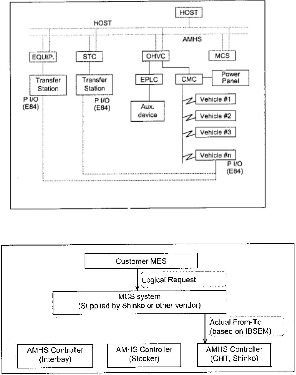
3.1.6 Total system configuration
Fig. 3.1.2 System Configuration (1)
Fig. 3.1.3 System Configuration (2)
FCC ID : OPO199909010001
KEN72-3696
17
Total system configuration is shown on Fig. 3.1.2 and Fig. 3.1.3.
Shinko OHT system does act for Intrabay transportation under the MCS, whether
the MCS is Shinko made or supplied by other vendors. Because OHVC (System
controller of Shinko OHT) is fully compliant with IBSEM (SEMI E82-0999) scenario,
open vendor system can be realized easily.
3.1.7 Transport rule
Customer’s HOST system shall send the transport requests to OHVC based on
IBSEM procedure (SEMI E82-0999). Refer to Chap. 7 for transport flow.

FCC ID : OPO199909010001
KEN72-3696
18
3.2 System Component and construction
3.2.1 System configuration
Table 3.2.1 shows the general condition of the system configuration limitation.
ITEM SPECIFICATION REMARKS
Configuration OHVC : 1 unit/ system (=bay)
OHV (Vehicle) : 60 units / system (Max.)
It is a logical restriction. Power
supply panel shall be designed
and supplied separately if more
than six vehicles are introduced.
Cover area OHV : within the close loop rail
Track length : 100 m – (Length of Feeder
Cable between Power Supply Panel to
Track connection point) / one Power
Supply Panel
By introducing multiple Power
Supply Panel, the track length
can be multiplied . (In standard
design maximum four Power
Supply Panel can be introduced).
Communicati
on
HOST-OHVC : ETHERNET
(SEMI E37.1 HSMS-SS)
OHVC – OHV : Power line communication
(EIA RS232C)
Tool - OHV : Photo I/O (SEMI E84)
Power Supply
Panel
(Normal,
5kW)
One panel covers the following
components
Rail length : 100 m – (Length of Feeder
Cable between Power Supply Panel to
Track connection point)
Power supply panel to Rail :100 m
OHV (Vehicle) : 6 units
Distance Between Power Supply
Panel to Rail can be extended if
the total length of Rail and this is
less than 100m.
Power Supply
Panel
(It is internally considered. But not
included in this specification. Followings
are the preliminary description)
One panel covers the following
components
Rail length : 100 m – (Length of Feeder
Cable between Power Supply Panel to
Track connection point)
Power supply panel to Rail :100 m
OHV (Vehicle) : 18 units
Table 3.2.1 System configuration

FCC ID : OPO199909010001
KEN72-3696
19
3.2.2 Component outline and quantity restriction
No Name Q’ty Description
1Track
Rail 1 A track rail has no electric instrument for controlling the vehicle
running.
Maintenance station (including lifting mechanism) is included in
the rail.
2 Power
supply
panel
1 Input : Three phase AC 200V ( standard ) or AC400V(Optional)
Output : 8.66 kHz (A.C 300 V to 400V, it depends on the
demand), single phase 5 kW, Air cooling
3 CMC 1 Communication unit between OHVC and vehicles
EIA RS485, 19.2 kBPS (TX/RX/CS procedure)
4 OHVC 1 OHV controller
IBM PC based Personal computer
RAID 1 Harddisk
Operating System : Microsoft Windows NT 4.0, US version
1 OHVC covers only 1 bay (= 1 close loop)
5 Vehicle Max. 60 Vehicle with hoist mechanism Driven by LDM
Main Controller : One board CPU IBM PC compatible
Operating System : Microsoft MS-DOS
6 Tool Max. 60 Load / Unload of a FOUP is done at the Load Port of
tools.(Customer’s facility)
7 Stocker Max. 10 Load / Unload of a FOUP is done at this stage.
(Customer’s facility)
Table 3.2.2 Component outline
3.2.3 Control System Interface
N
oName Media Protocol Remarks
1 OHVC-MCS ETHERNET
(10MBPS) HSMS-SS Software scenario is based on
IBSEM (SEMI E30.4)
2 OHVC-EPLC RS232C /
RS485
(19200BPS)
Original PLC supplier base
Maximum distance : 200m
3 OHVC-Vehicle
(Via CMC) RS232C /
RS485
(19200BPS)
Original Shinko original
Maximum distance : 200m
4 Vehicle-Tool
( or stocker) Photo I/O
8 bit SEMI E84 Based on SEMI
Table 3.2.3 System interface

FCC ID : OPO199909010001
KEN72-3696
20
3.2.4 Basic technical specification
ITEM SPECIFICATION REMARKS
Track structure One loop
Driven method LDM (Linear Direct-currency Motor)
Max. payload (kg-F) 10
Running speed, at straight (m/s) Max. 1.5
Running speed, at curve (m/s) 0.5
Running acceleration (m/s2)1.0
Hoisting speed (m/s) 1.0
Hoisting acceleration (m/s2)1.0
Hoist stroke (m) Max. 2.4
Carrier position Horizontal X,Y(mm) +/- 1
repeatability Height (mm) +/- 1
Vehicle stop Lateral(mm) +/- 30
position
compensation
Rotational (degree)
(horizontal space)
+/- 10
Cleanliness Less than CLASS 100 (0.2um)
Track radius (mm/r) 500 (at the center)
Carrier vibration 0.5G
Power supply to Vehicle Non contact , electro-magnetic coupling
Communi
-cation
Controller to vehicle Power line communication continuous, all area
Vehicle to Load port P I/O (E23, E84)
Track & Material Aluminum & Stainless Steel
support Cross section of track 270 (W) x 130 (H)
Vehicle
structure
Frame material Steel(Surface finishing)
Stainless steel & aluminum plate
Anti flammable plastic
Gripper Stainless steel & aluminum plate
Anti flammable plastic
Weight (kg) 80
Outline dimension (mm) 490(W) x 675(L) x 892(H)
Power supply
panel
INPUT/OUTPUT INPUT : AC208 V (three phase)
OUTPUT: (AC300V to 400V) , 8.66kHz, 5kW
(Standard)
Optional large power unit
can be offered.
(Normal one) Outline dimension &
structure
500(W) x 500(D) x 1600(H)
Air-cooling, Steel plate enclosure
(Output voltage depends
on Demand)
Controller Hardware PC/AT compatible Window NT PC
(OHVC) Software O/S : Window NT 4.0
HOST I/F : IBSEM compatible
(based on SEMI E30.4-0699)
Communication : HSMS (Ethernet)
FCC ID : OPO199909010001
KEN72-3696
21
3.2.5 Transfer station
The transfer stations shall be prepared by Customer and be compliant with SEMI
E15.1-0998 (1998). The input/output ports of stockers shall also be based on SEMI
E15.1-0998(1998) in shape and the height of them shall be mutually discussed.
All the center of the Load ports (including stocker I/O ports) shall be correctly under
the center of the OHT track within the predetermined accuracy ( +/- 30mm in lateral,
+/- 10 degrees in the horizontal surface). If the Load port is precisely under the track,
Shinko OHT vehicle can suddenly start the load/unload operation after the vehicle is
stopped, but if the load port position is not precisely under the track, position
compensation movement is necessary and the total performance might be lowered.
All the docking port of Load ports shall be in the direction (i.e. outer side of the loop).
P I/O device (based on SEMI E84) will be fixed on the track by Shinko at installation
stage based on the document supplied by Customer I advance, and the connection of
the cables between P I/O and the manufacturing tools shall be done by Customer.
3.2.6 Safety consideration
Following considerations may be supplied by Shinko based on the mutually agreed
discussion.
3.2.6.1 EMO ( Emergency Power OFF)
EMO switch is installed on the front surface of Power Supply Panel. By pressing this
button, power supply to all the vehicle in that system (generally in the bay) will be
suddenly stopped and all the vehicles will be suddenly stopped (stopped within three
seconds at worst).
Same function EMO switches can be added to the system optionally. Shinko will
supply the predetermined quantity of EMO switches and the installation (fixing in
adequate position) in the bay shall be done by Customer.
(Remarks)
Fixing position of EMO switch shall be decided by Customer considering the FAB
operation. According the SEMI S8 and other standards, the EMO position shall be
between 81 cm to 165 cm in height if the operators are standing position in work.
3.2.6.2 P I/O interlock with manufacturing tool
Shinko system is fully compliant with SEMI E84 in P I/O hand shaking. If ES
(Emergency Stop) signal from Passive side (Manufacturing tool) is activated, hoisting
movement of the corresponding vehicle will be suddenly stopped.
3.2.6.3 Estop on Vehicle
Estop button is installed on each vehicle. By pressing this button, vehicle movement
(traveling and hoisting gripping) will be suddenly stopped.
3.2.6.4 Envelope sensor
Each vehicle has a sensor system monitoring the envelope of its traveling area. By
this system, obstacles in front of the vehicle is detected and the collision will be
avoided. Refer to YDM-11859.
FCC ID : OPO199909010001
KEN72-3696
22
3.2.6.5 Fall protection arm
Each vehicle has fall protection arms, which tries to protect the FOUP in vehicle and
traveling position falling in the case of FOUP breakage.
3.2.6.6 Look down sensor
Each vehicle can be optionally added a look down sensor, which detects the
obstacles under the vehicle between the load port.
(It is under development, not yet completed.)
3.2.7 Separation of vehicles and operators
Even the Shinko system has the safety system offering above, it is strictly expected to
Customer for considering the separation of vehicles and operators, such as adding
partition or doors on the load port , or inhibit the operators moving into the bay.
3.2.8 Teaching
For registering the precise load port positions to vehicles, teaching operation is
necessary at the stage of Shinko adjustment work.
Refer to KEN72-3644(E) for details.
FCC ID : OPO199909010001
KEN72-3696
23
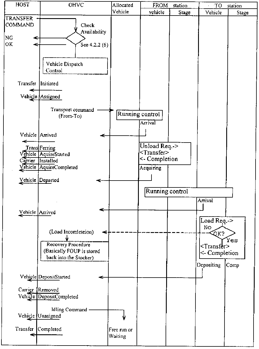
4. Transportation Control
Fig. 4.1 Basic transport flow

FCC ID : OPO199909010001
KEN72-3696
24
5. ERROR HANDLING
5.1 General
(1) The basic classification and handling is summarized in Table 5.1.
(2) When a vehicle was moved by outer power such as operator’s hand, following
recovery operation is necessary.
(2-1) Place all the vehicles on a normal position ( where it is not on branching position,
collecting position, etc. In case of OHT there is almost no need for consideration,
because the rail is simple loop.). If the moved distance of the vehicle can be
neglected small, it is not necessary. In case of moving, in front of the Bar code is
recommended.
Name Contents Handling Recovery
Heavy
error
The vehicle cannot
continue running
Total system mode is
changed to PAUSE and
all the vehicles stop
(1) Recover the error or
remove the error device
such as removal of the
error vehicle
(2) Then change the mode to
Auto
Medium
error
The vehicle can re-
start by operator’s
assist
(1) A vehicle can run
by himself
(2) Recover within 1
hour
Total system keeps the
same mode and the failed
devices are stopped
(1) Recover the error or
remove the error device such
as removal of the error
vehicle
Light
error
No needs for
operator’s assist for
re-start
Total system and the
failed device continue
Error event log is kept in
the OHVC
Table 5.1 Error group

FCC ID : OPO199909010001
KEN72-3696 25
5.2 Error handling
Error handling procedure is summarized in Table 5.2.1 and 5.2.2
Name Device Cause Countermeasure Recovery procedure
Heavy
Error Vehicle -Servo error
-Bar code read error
-Power unit error
-CPU failure
-Load /Unload error
(1) OHVC
1) Mode is moved to
PAUSED
2) ERROR indication
(2) Vehicle (error)
1) Emergency stop
2) Error reported to OHVC
3) Error indication by LED
(3) Vehicles (normal)
Paused
(1) Check and confirm the error cause
(2-1) Recovery can be expected soon
1) Reset of Vehicle power, Reset of other unit
2) OHVC is changed to Auto mode again
(2-2) Recovery might be long term
1) Remove the error unit such as error vehicle removal
2) Cancel the command which cannot be continued
3) OHVC is changed to Auto mode again
OHVC -OHVC-Vehicle
communication error
-Watch dog of transport
command
Others Power Supply Panel error (1) Check and confirm the error cause
(2) Confirm the vehicle position is OK
(3) Restart of the system
Medium
Error Vehicle Time-over of Obstacle
Detection sensor
(1) OHVC
Continues Auto mode
operation
(2) Vehicle (error)
Continue operation
Error report to OHVC
(3) Vehicles (normal)
Continues normal
operation
(1) Check and confirm the error cause
(2-1) Recovery can be expected by operator assist
1) Recovery by operator such as removal o
f
obstacles
2) Continues the process
In case detect sensor : automatic restart
(2-2) Recovery cannot be expected
1) Mode changed to PAUSING by OHVC operation
2) same with Heavy error recovery
OHVC

FCC ID : OPO199909010001
KEN72-3696 26
OTHERS
Table 5.2.1

FCC ID : OPO199909010001
KEN72-3696 27
Name Device Cause Countermeasure Recovery procedure
Light
Error Vehicle (1) OHVC
1) Auto mode operation
continues
2) Event is kept by OHVC
(2) Vehicle (error)
1) continue normal operation
2) Error reported to OHVC
(3) Vehicles (normal)
Continues normal operation
(1) No assist necessary
(2) In case of special failure special procedure might b
e
done (such as Carrier status error, automati
c
transport to stocker)
OHVC - Transport request
rejected
- Host communication
error
OTHERS
Table 5.2.2

FCC ID : OPO199909010001
KEN72-3696 28
5.3 Recovery procedure in case of Heavy error of a vehicle
HOST/STC OHVC Vehicle Operator action
Fig. 5.3 Error recovery procedure

FCC ID : OPO199909010001
KEN72-3696
29
6. Operation
The documents listed in Table 6.1 are operation manual of components.
Regarding the operation of the OHT system, refer to these documents.
Table 6.1 Related Documents
No Name Document Number Rev. Remarks
1 OHT Vehicle Operation Manual KEN72-3699 (E) 0
2 OHT Teaching Manual KEN72-3644(E) 1
3 Power Supply Operation Manual YTE7-1002
4 Operation Manual of OHVC CRP6T3142-01E A
5 Remote Control Box Operation
Manual
KEN72-3502(E) 1
6

FCC ID : OPO199909010001
KEN72-3696
30
Revision Note
# Revision Month/Day/Year Contents Author
#1 Rev.0 Sept. 3, 1999 The first edition(Preliminary) Masanao Murata