Siemens Canada Siemens Milltronics Process Instruments LR250 SITRANS LR 250 TANK LEVEL PROBING RADAR User Manual SITRANS LR250 mA HART
Siemens Canada Ltd. - Siemens Milltronics Process Instruments SITRANS LR 250 TANK LEVEL PROBING RADAR SITRANS LR250 mA HART
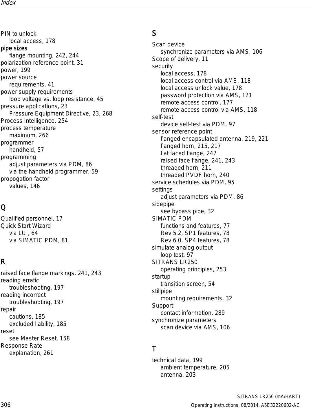
Contents
User Manual 2


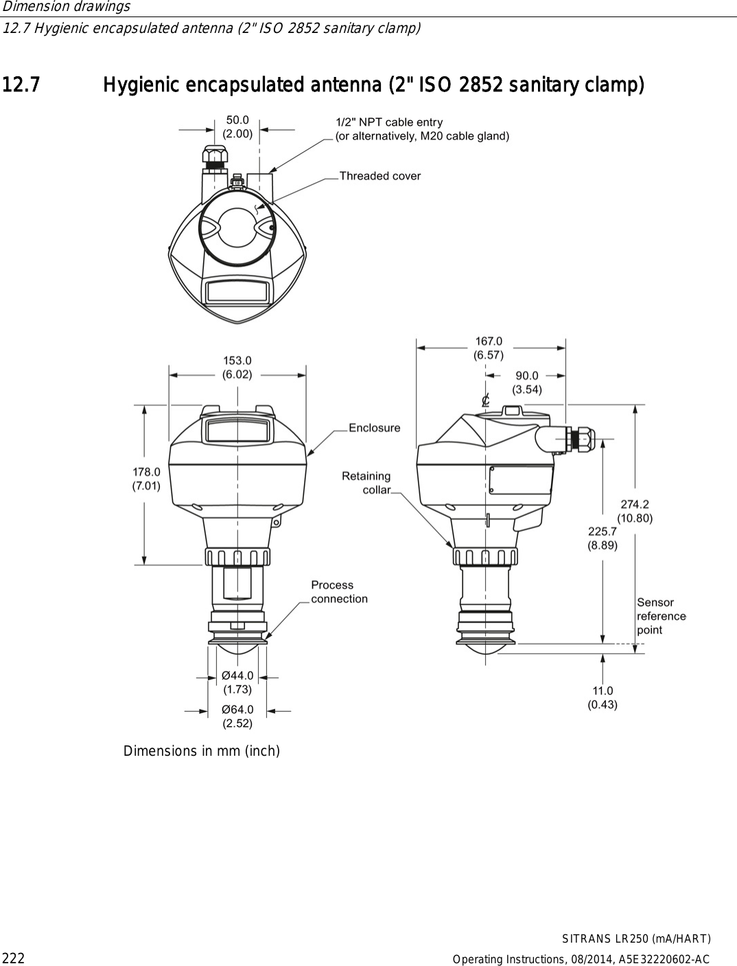
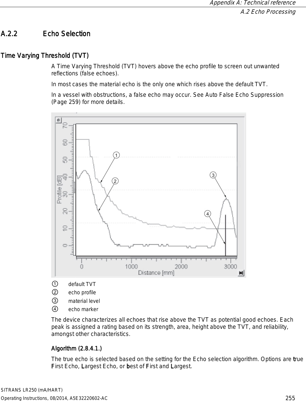
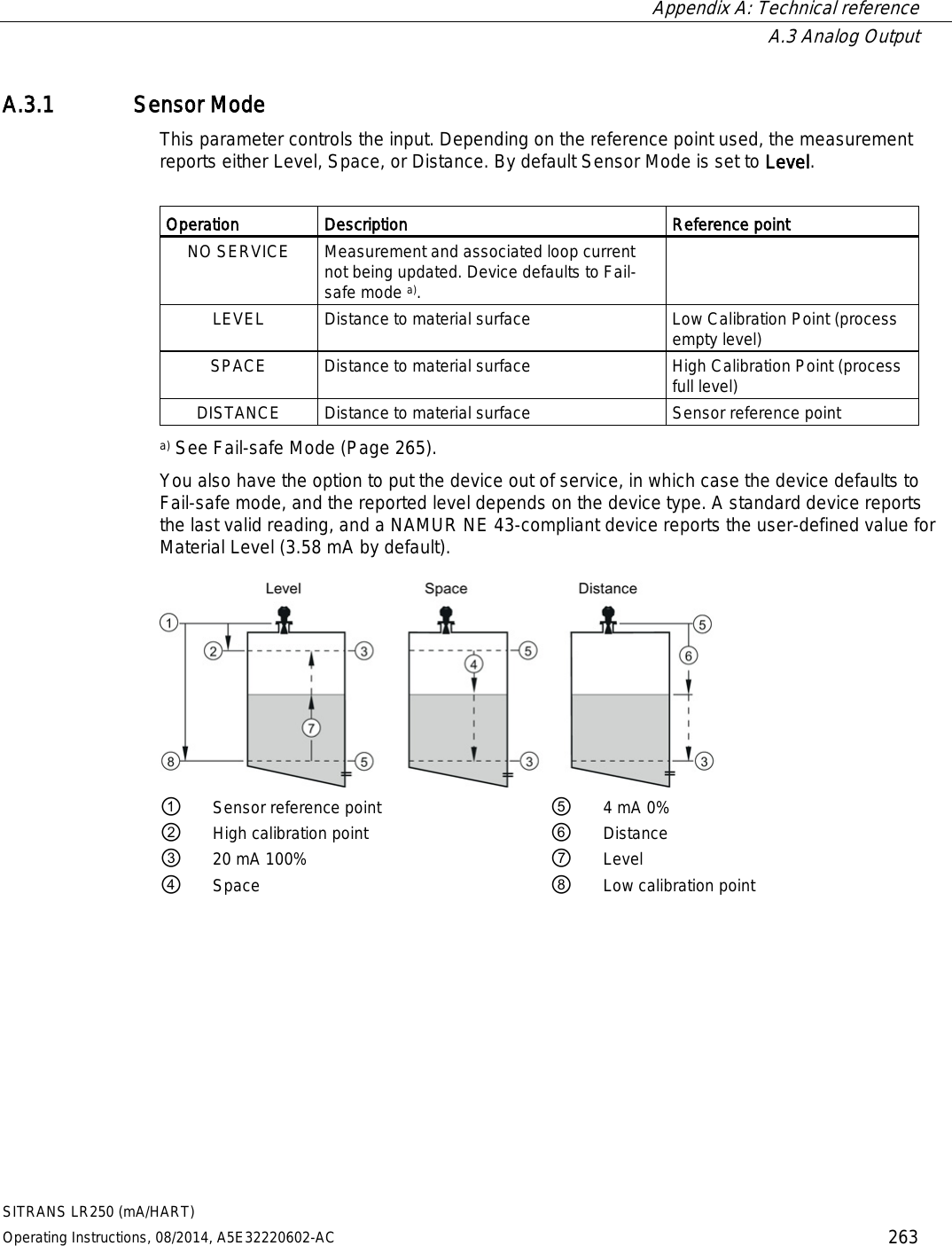
![Technical data 11.2 Performance SITRANS LR250 (mA/HART) 200 Operating Instructions, 08/2014, A5E32220602-AC Maximum measurement range4) 1.5" antenna 10 m (32.8 ft)5) 2" threaded PVDF antenna 2"/DN50/50A Flanged encapsulated antenna (FEA) 2" ISO 2852, DN50 DIN 11864-1/2/3, DN50 DIN11851, Tuchenhagen Types F and N Hygienic encapsulated antenna (HEA) all other versions 20 m (65.6 ft) Minimum detectable distance 50 mm (2") from end of antenna6) Update time7) minimum 1 second, depending on settings for Response Rate (2.4.1.) and LCD Fast Mode (4.9.) Influence of ambient temperature < 0.003%/K (average over full temperature range, referenced to maximum range) Dielectric constant of material measured dK > 1.6 [antenna and application dependent8)] Memory non-volatile EEPROM no battery required 1) The statistical accuracy is typically 3 mm (0.12") 90% of the time, when tested in accordance with IEC 60770-1. 2) Under severe EMI/EMC environments per IEC 61326-1 or NAMUR NE21, the device error may increase to a maximum of 10 mm (0.4"). 3) For 2" threaded PVDF, Flanged encapsulated antennas and Hygienic encapsulated antennas, the maximum measured error <500 mm from the sensor reference point =25 mm (1"). 4) From sensor reference point: see Dimensions (Page 209). 5) 20 m (65.6 ft) possible in a stillpipe/bypass 6) Minimum range is antenna length + 50 mm (2"). See Dimension drawings (Page 209). 7) Reference conditions: Response Rate (2.4.1.) set to FAST, LCD Fast Mode (4.9.) set to ON. 8) For 1.5" (40 mm) antenna, 2" (50 mm) threaded PVDF antenna, 2"/DN50/50A flanged encapsulated antenna, and 2" ISO 2852, DN50 DIN 11864-1/2/3, DN50 DIN11851, Tuchenhagen Types F and N hygienic encapsulated antenna the dK is limited to 3 unless a stillpipe is used. See Flanged horn antenna (Page 214). See Flanged encapsulated antenna (3"/DN80/80A sizes and larger) (Page 220). See Hygienic encapsulated antenna (2" ISO 2852 sanitary clamp) (Page 222).](https://usermanual.wiki/Siemens-Canada-Siemens-Milltronics-Process-Instruments/LR250.User-Manual-2/User-Guide-2277917-Page-18.png)
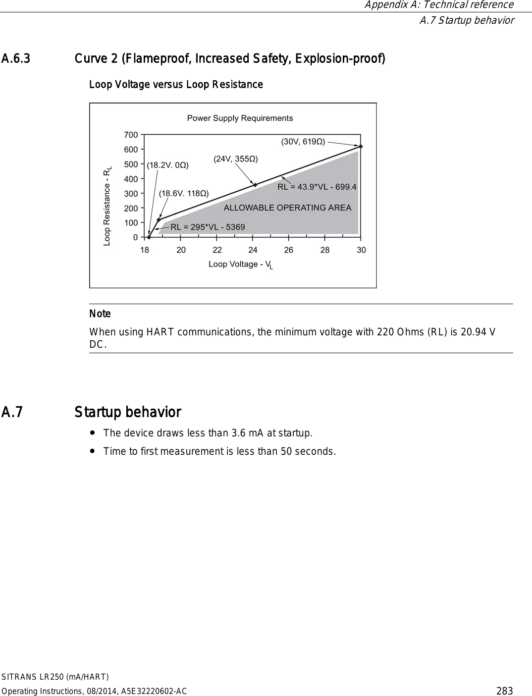
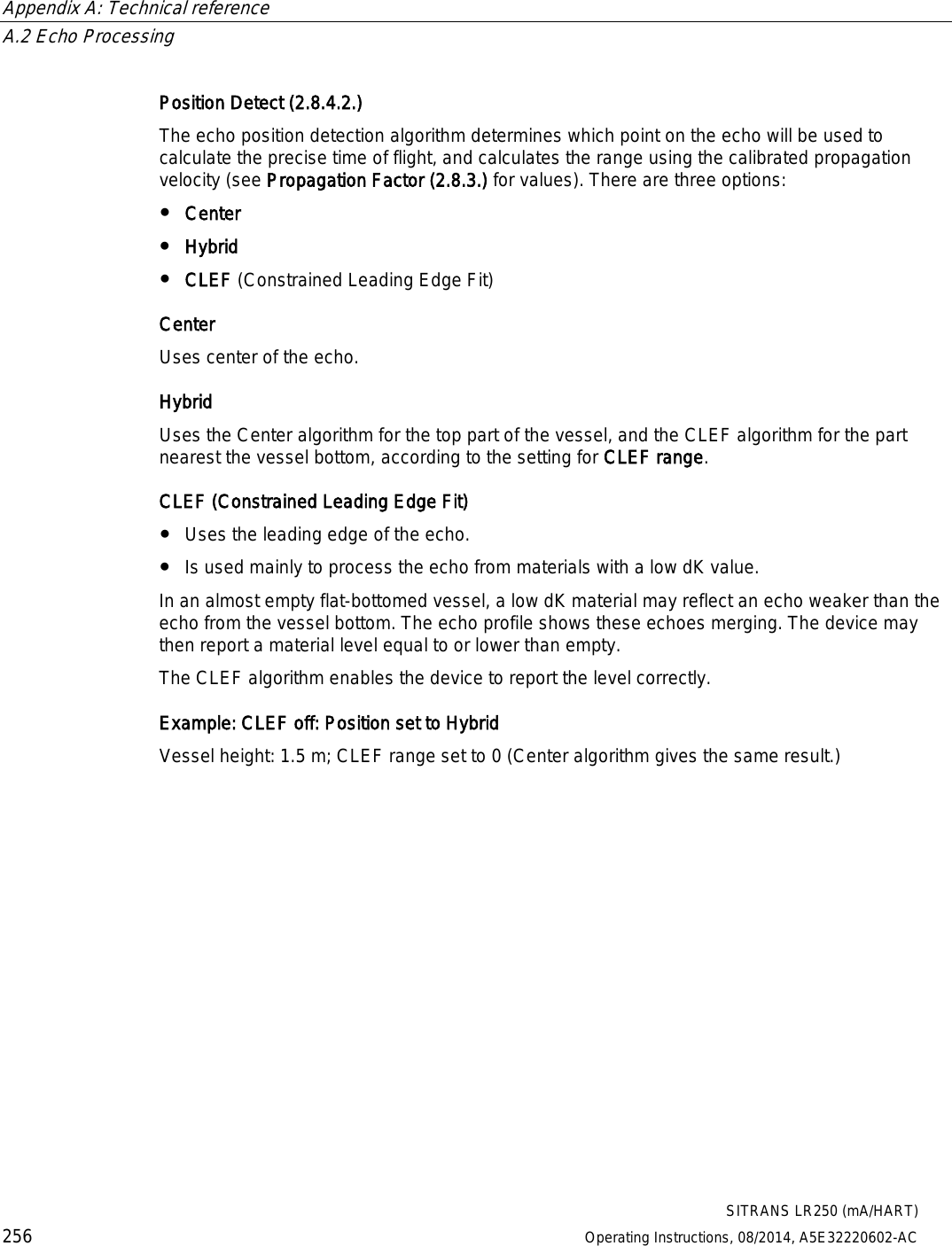
![Technical data 11.3 Interface SITRANS LR250 (mA/HART) Operating Instructions, 08/2014, A5E32220602-AC 201 11.3 Interface Analog output Signal range 4 to 20 mA (± 0.02 mA accuracy) upper limit 20 to 23 mA adjustable Fail signal 3.6 mA to 23 mA [For more details, see Fail-safe Mode] (Page 265) Communication: HART1) Load 230 to 600 Ω, 230 to 500 Ω when connecting a coupling module Max. line length multi-wire: ≤ 1500 m (4921 ft) Protocol HART, Version 5.1 Configuration Remote Siemens SIMATIC PDM or AMS Device Manager (PC) Local Siemens infrared handheld programmer, or HART handheld communicator Display (local)2) graphic LCD, with bar graph representing level 1) See A.6.3 for details on version exclusions 2) Display quality will be degraded in temperatures below –25 °C (–13 °F) and above +65 °C (+149 °F). Curve 2 (Flameproof, Increased Safety, Explosion-proof) (Page 283)](https://usermanual.wiki/Siemens-Canada-Siemens-Milltronics-Process-Instruments/LR250.User-Manual-2/User-Guide-2277917-Page-19.png)
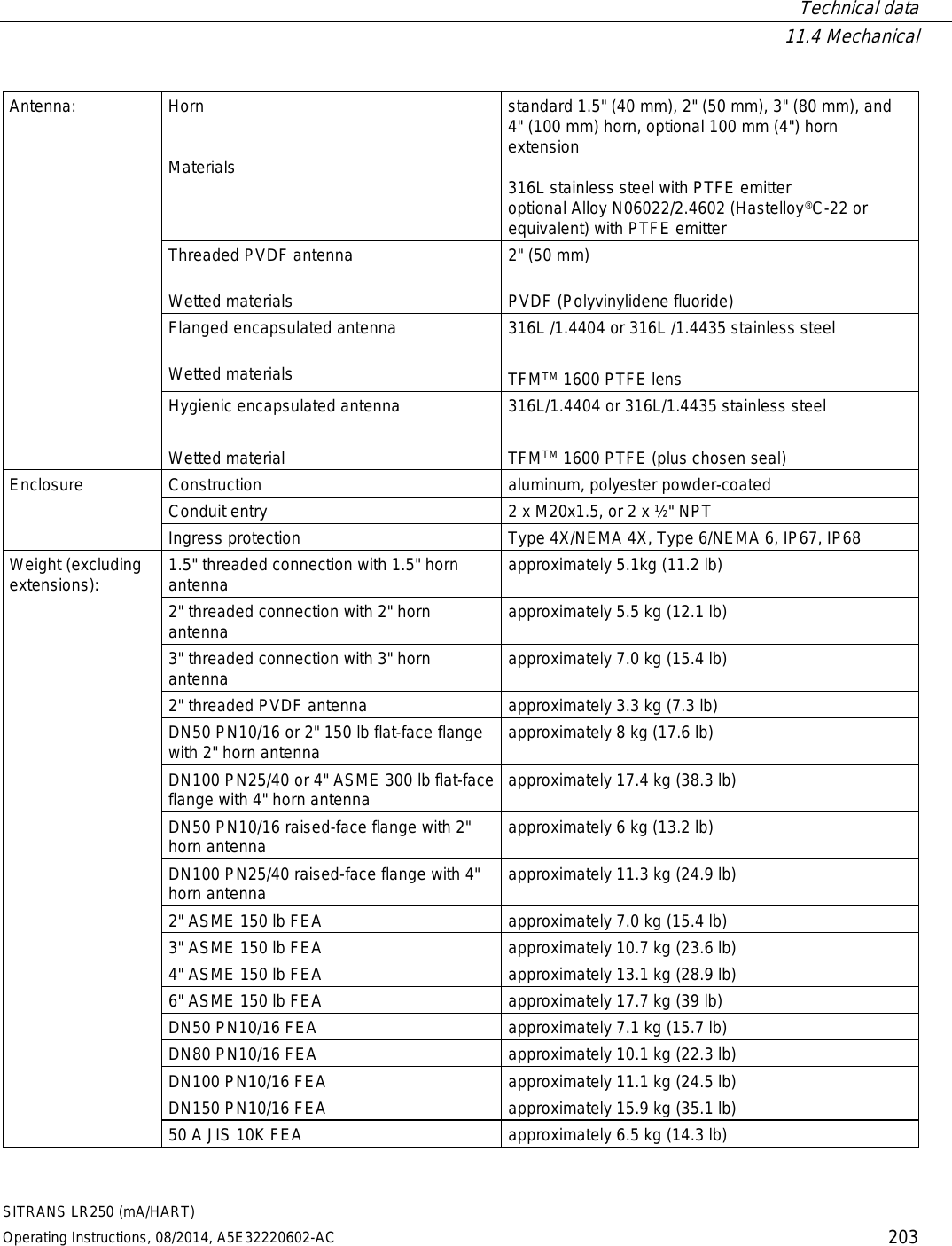
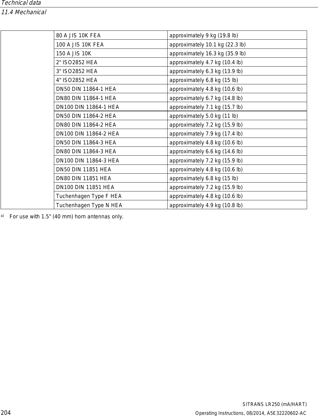
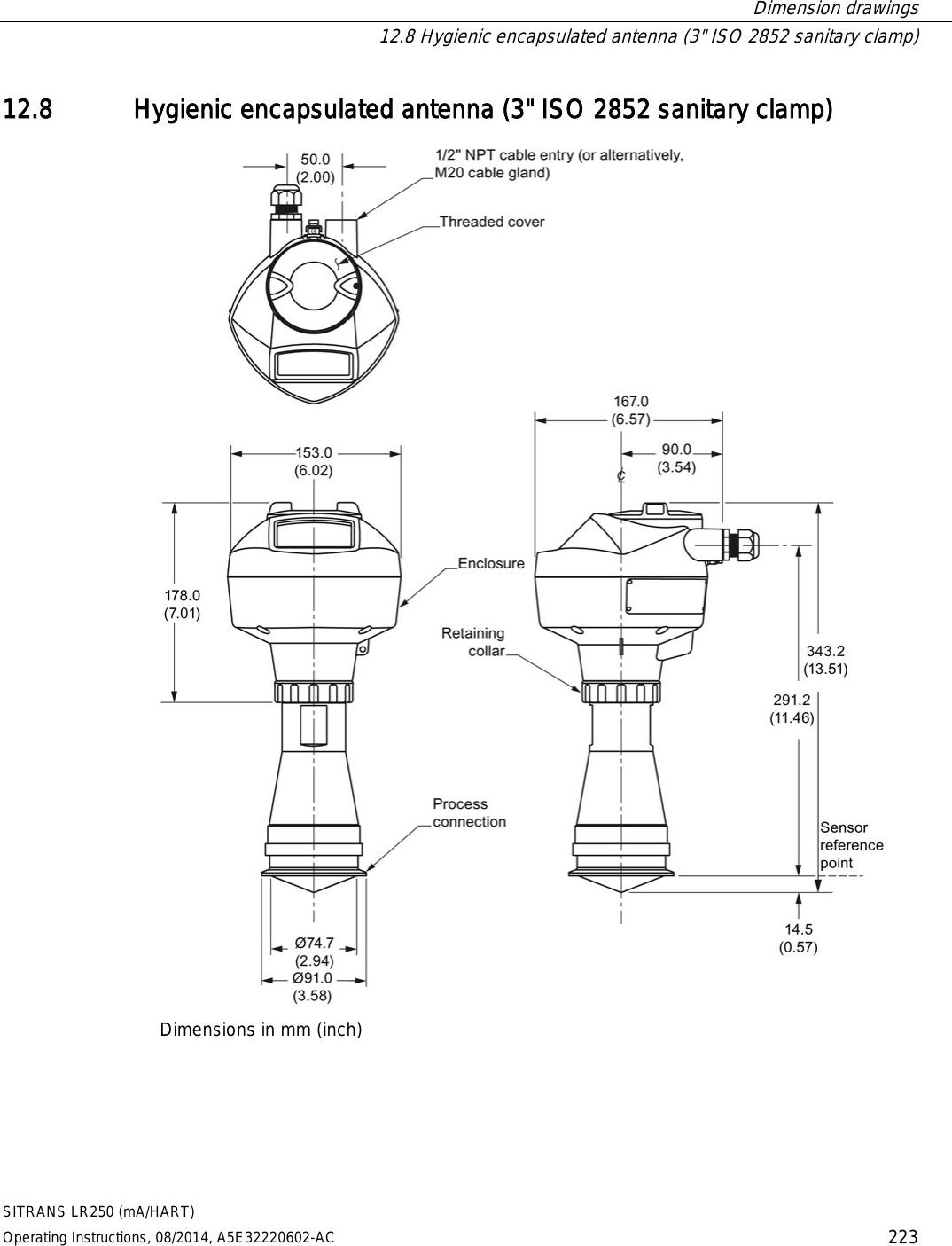
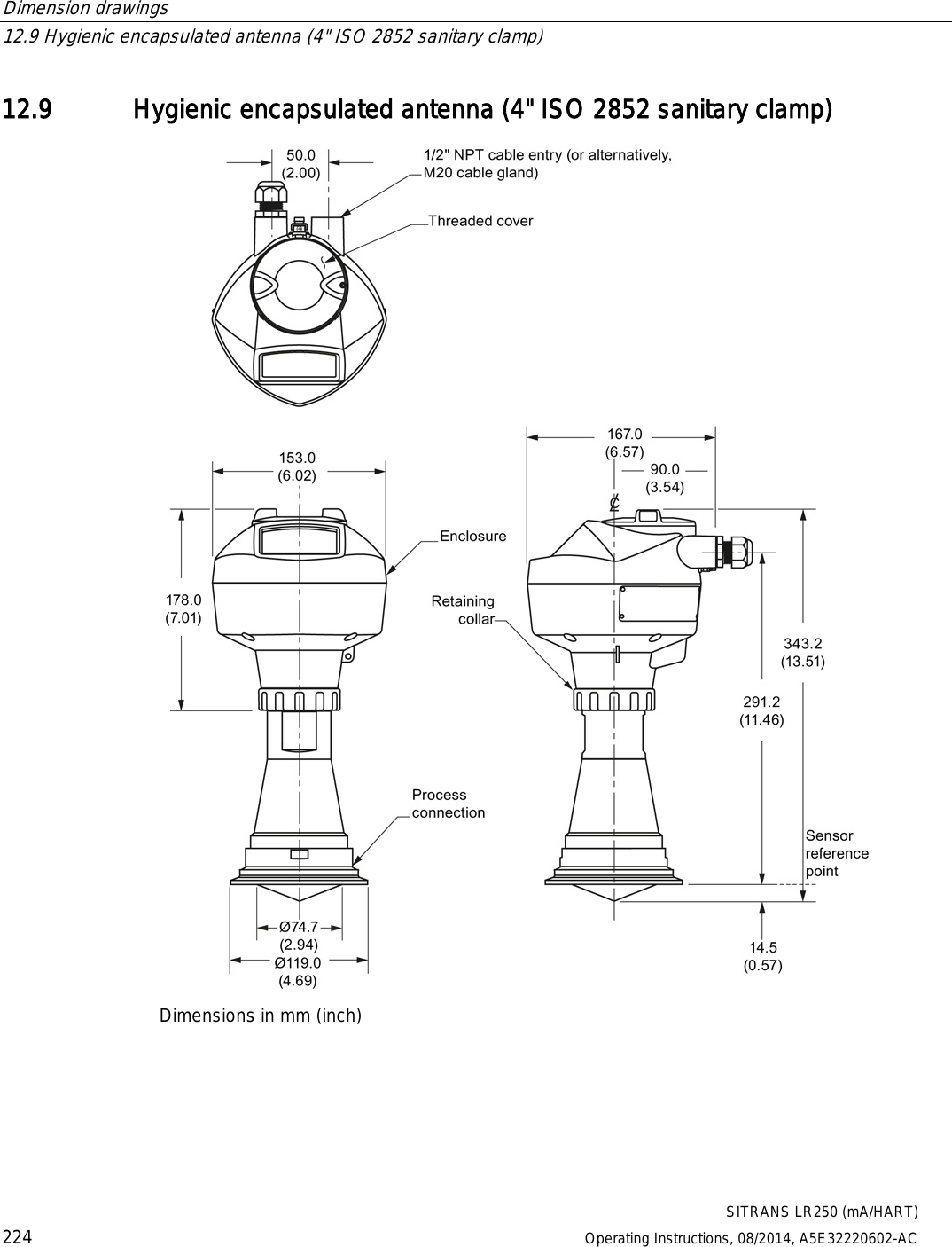
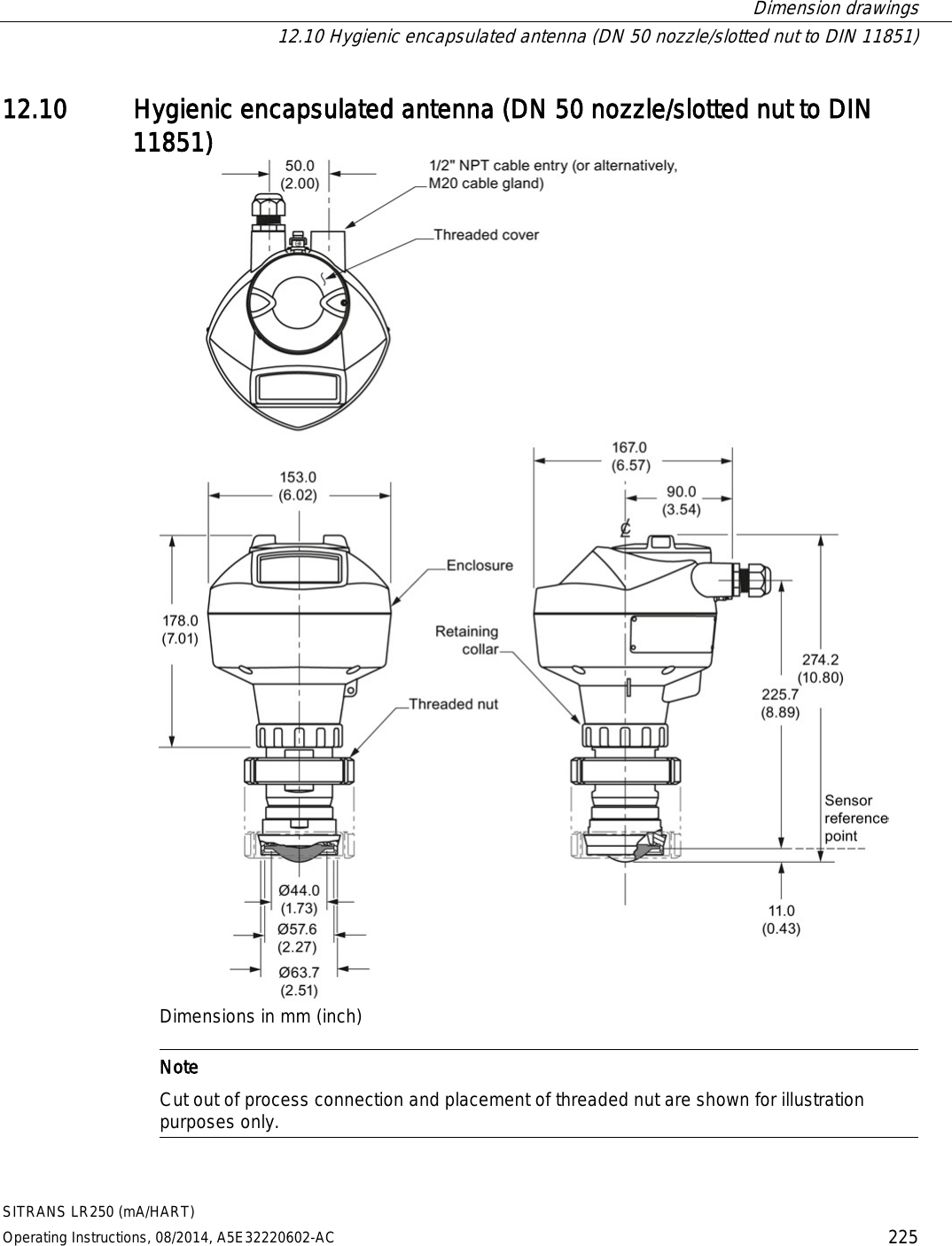
![Technical data 11.4 Mechanical SITRANS LR250 (mA/HART) 202 Operating Instructions, 08/2014, A5E32220602-AC 11.4 Mechanical Process connection: Threaded connection 1.5" NPT (ASME B1.20.1), R (BSPT, EN 10226-1) a) or G (BSPP, EN ISO 228-1) or 2" NPT (ASME B1.20.1), R (BSPT, EN 10226-1) or G (BSPP, EN ISO 228-1) or 3" NPT (ASME B1.20.1), R (BSPT, EN 10226-1) or G (BSPP, EN ISO 228-1) Flange connection (flat-face) Materials 2, 3, 4" (ASME 150 lb, 300 lb) DN50, DN80, DN100 (PN10/16, PN25/40) 50A, 80A, 100A (JIS 10K) 316L /1.4404 or 316L /1.4435 stainless steel Flange connection (raised face) Materials DN50, DN80, DN100, DN150 (PN10/16, PN25/40) 1.4404 or 1.4435 stainless steel, optional Alloy N06022/2.4602 (Hastelloy®C-22 or equivalent) Flanged encapsulated antenna (FEA) connection (raised face) Materials 2, 3, 4, 6" (ASME 150 lb); DN50, DN80, DN100, DN150 (PN10/16); 50A, 80A, 100A, 150A (JIS 10K) 316L /1.4404 or 316L /1.4435 stainless steel Hygienic encapsulated antenna (HEA) connection Materials ISO 2852 (2, 3, 4") DIN 11851 (DN50, DN80, DN100) DIN 11864-1/2/3 (DN50, DN80, DN100) Tuchenhagen (Type F [50 mm] and Type N [68 mm]) 316L /1.4404 or 316L /1.4435 stainless steel ISO 2852 (2, 3, 4") DIN 11864-3 (DN50, DN80, DN100) clamp: 304/1.4301 stainless steel Tuchenhagen (Type F [50 mm] and Type N [68 mm]) 316L /1.4404 or 316L /1.4435 stainless steel clamp: 304/1.4301 stainless steel nut connection: 303/1.4305 stainless steel DIN 11851/11864-1 (DN50, DN80, DN100) captive slotted nut connection: 304L/1.4307 DIN 11864-2 (DN50, DN80, DN100) mounting nuts and bolts: 304/1.4301 stainless steel](https://usermanual.wiki/Siemens-Canada-Siemens-Milltronics-Process-Instruments/LR250.User-Manual-2/User-Guide-2277917-Page-20.png)
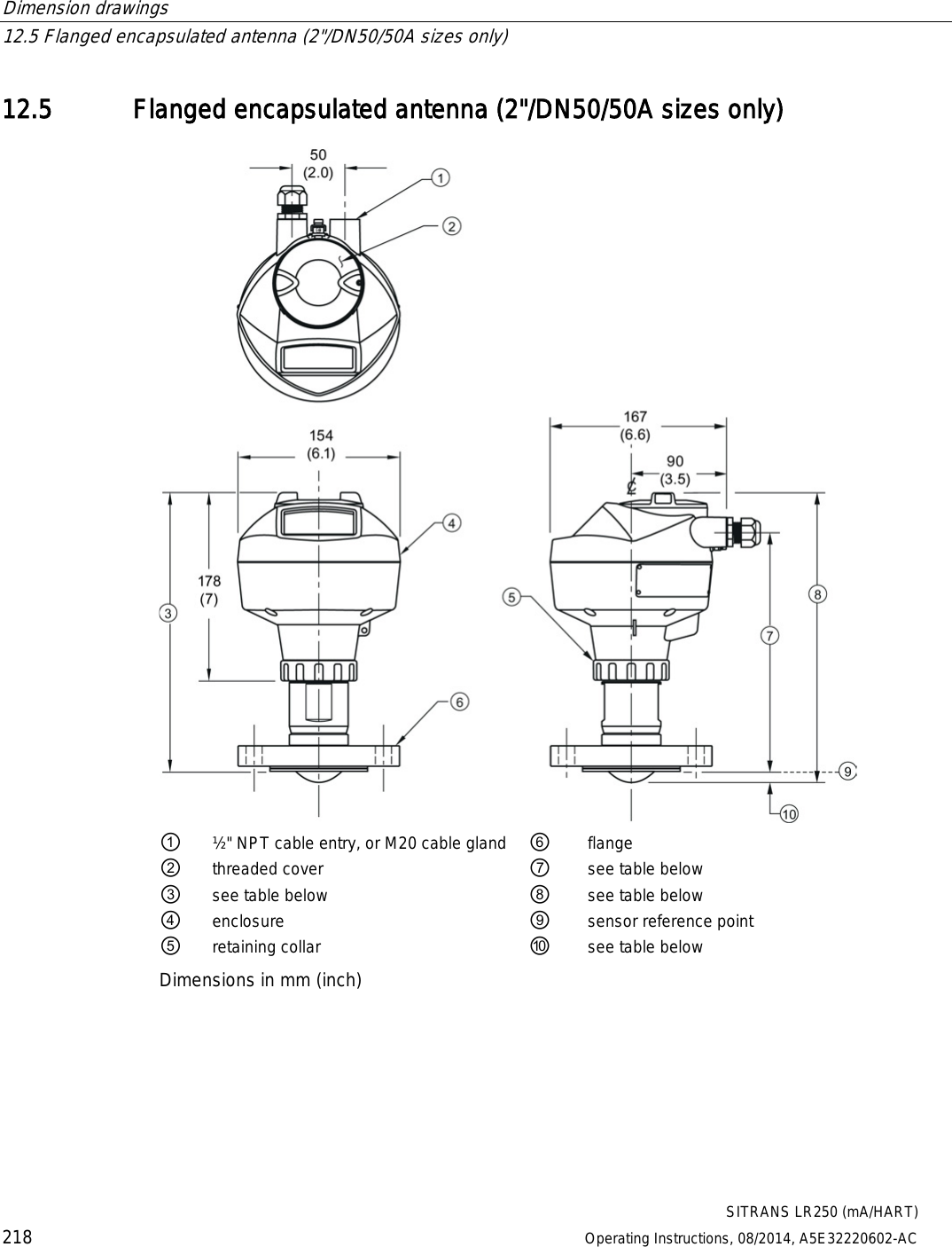
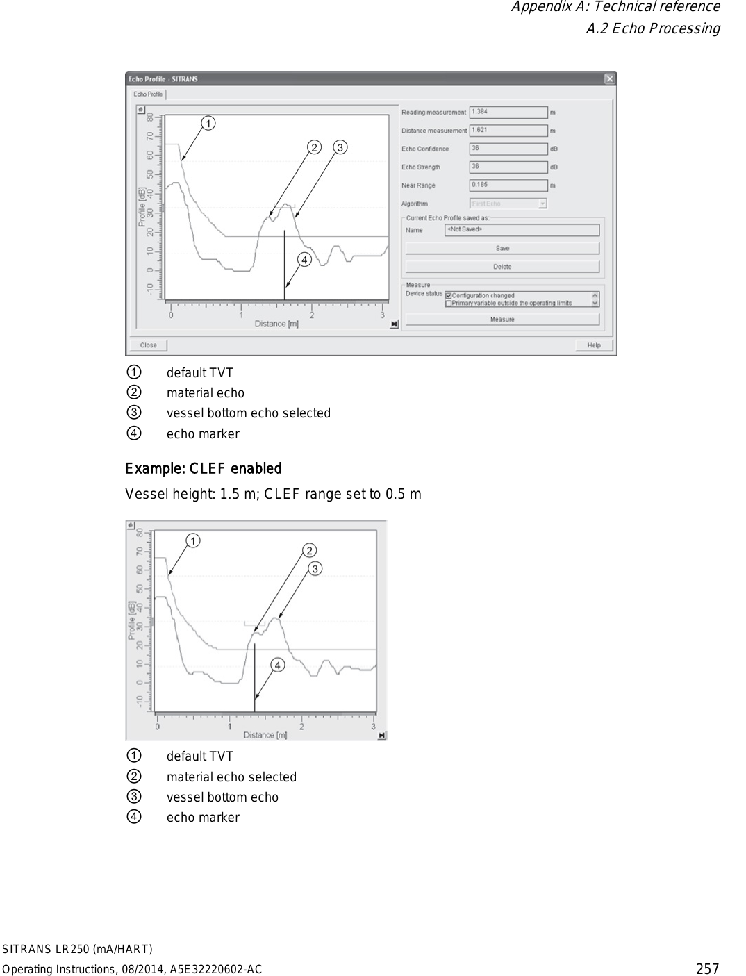
![Dimension drawings 12.5 Flanged encapsulated antenna (2"/DN50/50A sizes only) SITRANS LR250 (mA/HART) Operating Instructions, 08/2014, A5E32220602-AC 219 Flanged encapsulated antenna (2"/DN50/50A) dimensions Flange size ③ mm (inch) ⑦ mm (inch) ⑧ mm (inch) ⑩ mm (inch)1) 2"/DN50/50A 263 (10.35) 223 (8.78) 274 (10.79) 11 (0.43) 1) Height from tip of lens to sensor reference point as shown. Flange size Flange class Flange O.D. [mm (inch)] Antenna aperture size [mm (inch)] Beam angle (°)1) Measurement range [m (ft)] 2" 150 LB 152 (5.98) 50 (1.97) 12.8 10 (32.8)2) DN50 PN10/16 165 (6.50) 50A 10K 155 (6.10) 1) -3 dB in the direction of the polarization axis. 2) 20m if installed in stillpipe See Raised-Face Flange per EN 1092-1, (Page 243)and Polarization reference point (Page 31).](https://usermanual.wiki/Siemens-Canada-Siemens-Milltronics-Process-Instruments/LR250.User-Manual-2/User-Guide-2277917-Page-37.png)
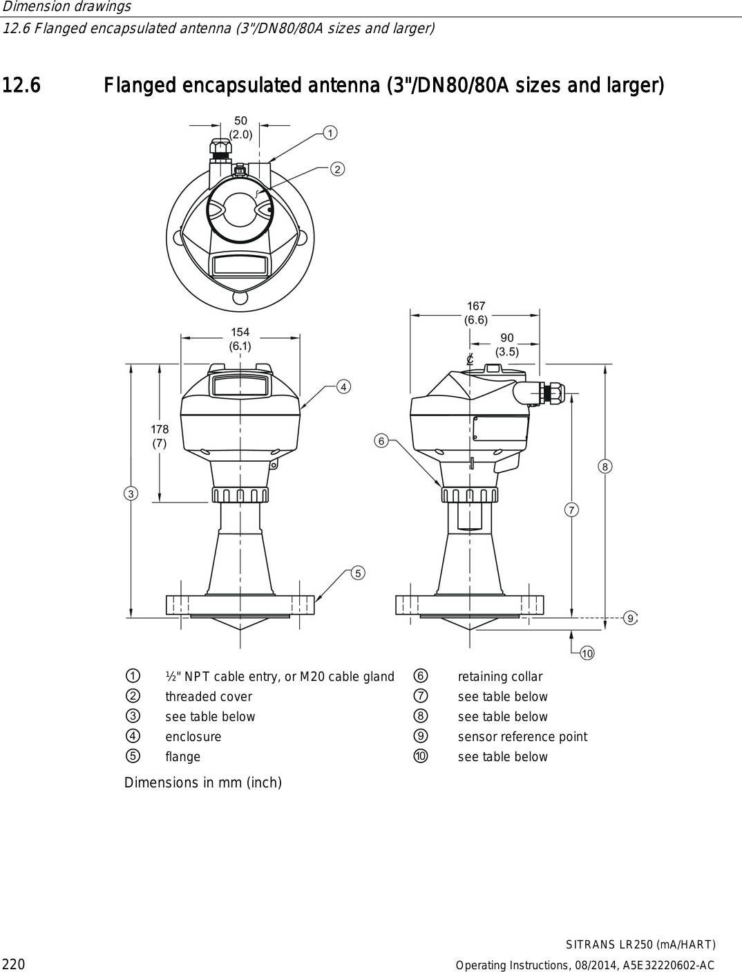
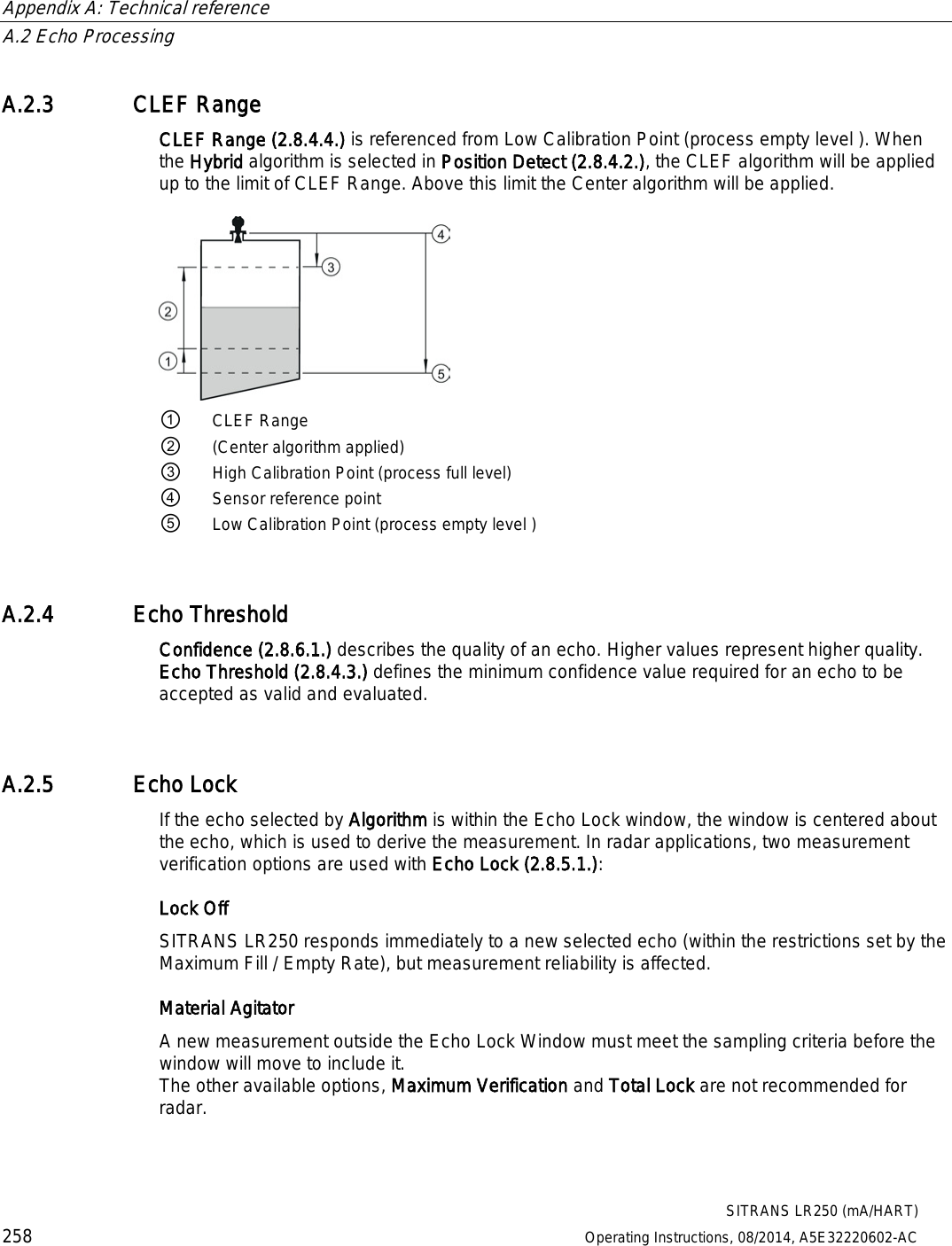
![Dimension drawings 12.6 Flanged encapsulated antenna (3"/DN80/80A sizes and larger) SITRANS LR250 (mA/HART) Operating Instructions, 08/2014, A5E32220602-AC 221 Flanged encapsulated antenna (3"/DN80/80A and larger) dimensions Flange size ③ mm (inch) ⑦ mm (inch) ⑧ mm (inch) ⑩ mm (inch)1) 3"/DN80/80A 328 (12.91) 288 (11.34) 343 (13.50) 15 (0.59) 4"/DN100/100A 328 (12.91) 288 (11.34) 343 (13.50) 13 (0.51) 6"/DN150/150A 333 (13.11) 293 (11.54) 348 (13.70) 15 (0.59) 1) Height from tip of lens to sensor reference point as shown. See also Raised-Face Flange per EN 1092-1. Flange size Flange class Flange O.D. [mm (inch)] Antenna aperture size [mm (inch)] Beam angle (°)1) Measurement range [m (ft)] 3" 150 LB 190 (7.48) 75 (2.95) 9.6 20 (65.6) DN80 PN10/16 200 (7.87) 80A 10K 185 (7.28) 4" 150 LB 230 (9.06) 75 (2.95) 9.6 20 (65.6) DN100 PN10/16 220 (8.66) 100A 10K 210 (8.27) 6" 150 LB 280 (11.02) 75 (2.95) 9.6 20 (65.6) DN150 PN10/16 285 (11.22) 150A 10K 280 (11.02) 1) -3 dB in the direction of the polarization axis. See Raised-Face Flange per EN 1092-1 (Page 243), and Polarization reference point (Page 31).](https://usermanual.wiki/Siemens-Canada-Siemens-Milltronics-Process-Instruments/LR250.User-Manual-2/User-Guide-2277917-Page-39.png)
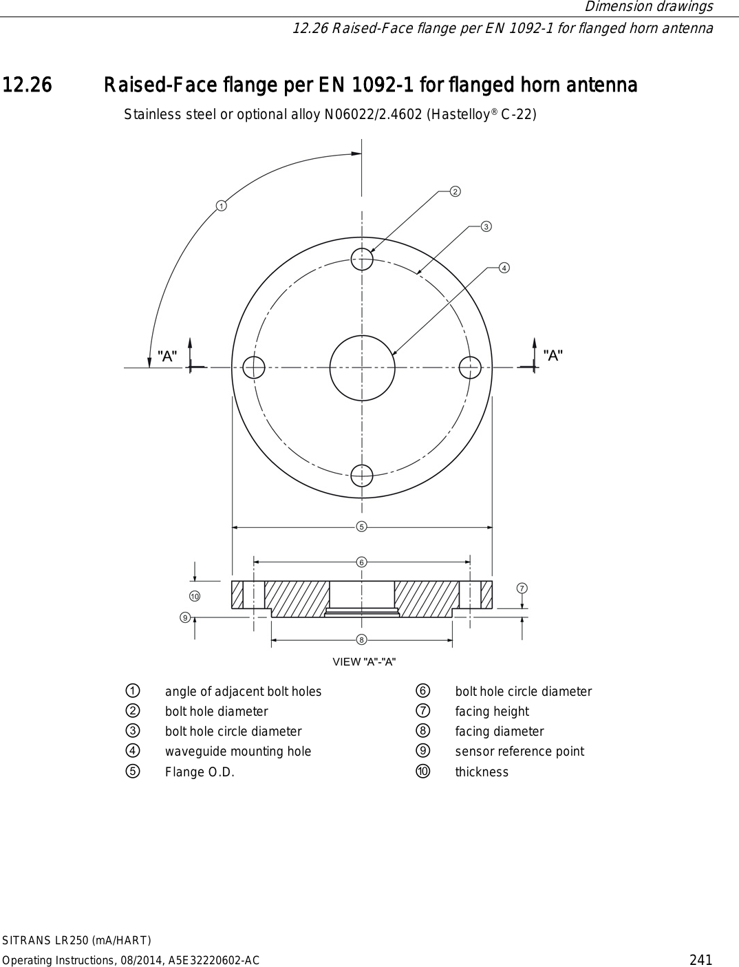
![Dimension drawings 12.26 Raised-Face flange per EN 1092-1 for flanged horn antenna SITRANS LR250 (mA/HART) 242 Operating Instructions, 08/2014, A5E32220602-AC Raised-Face flange dimensions Pipe size Flange bolt hole pattern ⑤ Flange O.D. (mm) ③ Bolt hole circle Ø (mm) ② Bolt hole Ø (mm) No. of bolts ① Angle of adjacent bolt holes ⑧ Facing Ø (mm) ⑩ Thickness (mm) DN50 PN10/PN16 165 125 18 4 90 102 18 DN80 PN10/PN16 200 160 18 8 45 138 20 DN100 PN10/PN16 220 180 18 8 45 158 20 DN150 PN10/PN16 285 240 22 8 45 212 22 DN50 PN25/PN40 165 160 18 4 90 138 20 DN80 PN25/PN40 200 160 18 8 45 138 24 DN100 PN25/PN40 235 190 22 8 45 162 24 DN150 PN25/PN40 300 250 26 8 45 218 28 Raised-Face flange markings Blind Flange Markings (Optional Manufacturer’s Logo [optional]; Flange Standard; Nominal Size; Material; Heat Code) Machining Identification Welded Assembly Identification a) Serial no. Logo Flange series Flange series Heat Code no. Facing Manufacturer’s logo; EN 1092-1 05 ‘B1’; ‘DN50’ ‘PN16’ ‘1.4404 or 1.4435’ A1B2C3 mmddyyxxx xxxxx xxxxx A1B2C3 RF a) When flange material is alloy N06022/2.4602, additional material and heat code identification is provided. The flange markings are located around the outside edge of the flange. Serial number: a unique number allotted to each flange, including the date of manufacture (MMDDYY) followed by a number from 001 to 999 (indicating the sequential unit produced). Flange series: the Siemens Milltronics drawing identification. Heat code: a flange material batch code identification.](https://usermanual.wiki/Siemens-Canada-Siemens-Milltronics-Process-Instruments/LR250.User-Manual-2/User-Guide-2277917-Page-60.png)
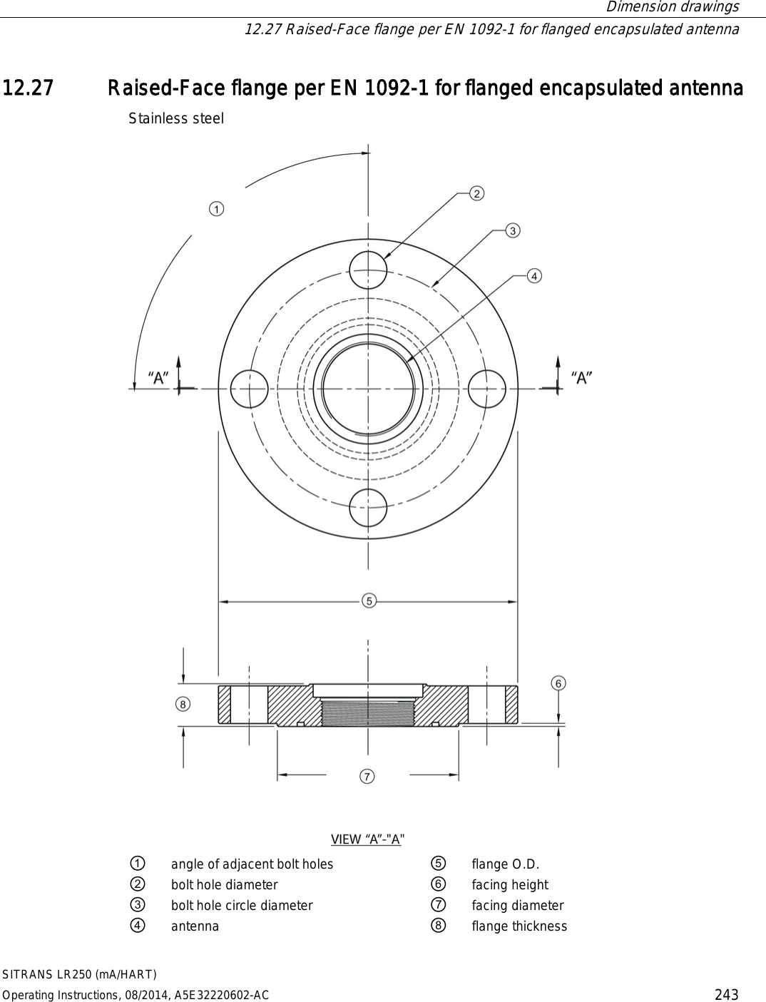
![Dimension drawings 12.27 Raised-Face flange per EN 1092-1 for flanged encapsulated antenna SITRANS LR250 (mA/HART) 244 Operating Instructions, 08/2014, A5E32220602-AC Raised-Face flange dimensions Pipe size Flange class ⑤ Flange O.D. [mm (inch)] ③ Bolt hole circle Ø [mm (inch)] ② Bolt hole Ø [mm (inch)] No. of bolt holes ① Angle of adjacent bolt holes ⑦ Facing Ø [mm (inch)] ⑨ Flange thickness [mm (inch)] ⑥ Flange facing thickness [mm (inch)] 2" 150 LB 152 (5.98) 120.7 (4.75) 19 (0.75) 4 90 92.1 (3.63) 20.6 (0.81) 1.5 (0.06) 3" 190 (7.48) 152.4 (6.00) 127 (5.00) 25.9 (1.02) 2 (0.08) 4" 230 (9.06) 190.5 (7.50) 8 45 157.2 (6.19) 2 (0.08) 6" 280 (11.02) 241.3 (9.50) 22.2 (0.87) 215.9 (8.50) 26.9 (1.06) 1.5 (0.06) DN50 PN10/16 155 (6.10) 125 (4.92) 18 (0.71) 4 90 102 (4.02) 18 (0.71) 2 (0.08) DN80 200 (7.87) 160 (6.30) 8 45 138 (5.43) 20 (0.79) 2 (0.08) DN100 220 (8.66) 180 (7.09) 158 (6.22) 2 (0.08) DN150 285 (11.22) 240 (9.45) 22 (0.87) 212 (8.35) 22 (0.87) 2 (0.08) 50A 10K 155 (6.10) 120 (4.72) 19 (0.75) 4 90 96 (3.78) 16 (0.63) 2 (0.08) 80A 185 (7.28) 150 (5.91) 8 45 126 (4.96) 18 (0.71) 2 (0.08) 100A 210 (8.27) 175 (6.89) 151 (5.94) 2 (0.08) 150A 280 (11.02) 240 (9.45) 23 (0.91) 212 (8.35) 22 (0.87) 2 (0.08)](https://usermanual.wiki/Siemens-Canada-Siemens-Milltronics-Process-Instruments/LR250.User-Manual-2/User-Guide-2277917-Page-62.png)
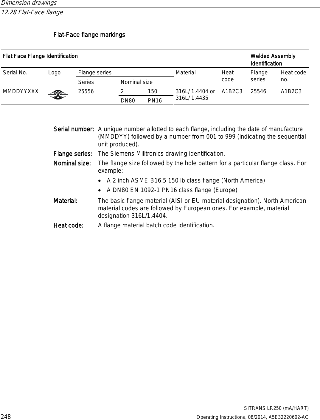
![Dimension drawings 12.27 Raised-Face flange per EN 1092-1 for flanged encapsulated antenna SITRANS LR250 (mA/HART) Operating Instructions, 08/2014, A5E32220602-AC 245 Raised-Face flange markings Blind Flange Markings (Optional Manufacturer’s Logo [optional]; Flange Standard; Nominal Size; Material; Heat Code) Machining Identification Welded Assembly Identification Serial no. Logo Flange series Flange series Heat Code no. Facing Manufacturer’s logo; EN 1092-1 05 ‘B1’; ‘DN50’ ‘PN16’ ‘1.4404 or 1.4435’ A1B2C3 mmddyyxxx xxxxx xxxxx A1B2C3 RF The flange markings are located around the outside edge of the flange. Serial number: a unique number allotted to each flange, including the date of manufacture (MMDDYY) followed by a number from 001 to 999 (indicating the sequential unit produced). Flange series: the Siemens Milltronics drawing identification. Heat code: a flange material batch code identification.](https://usermanual.wiki/Siemens-Canada-Siemens-Milltronics-Process-Instruments/LR250.User-Manual-2/User-Guide-2277917-Page-63.png)
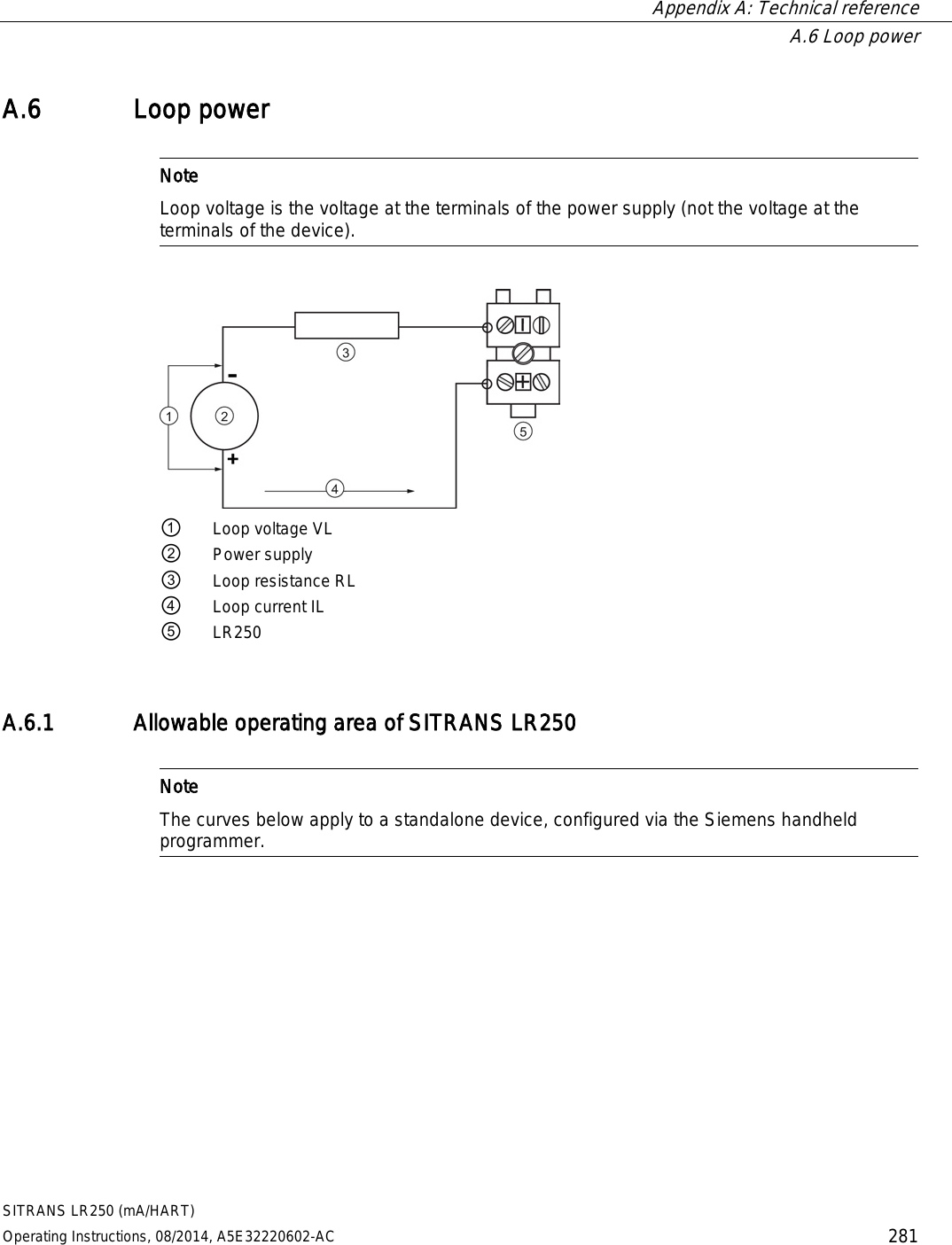
![SITRANS LR250 (mA/HART) Operating Instructions, 08/2014, A5E32220602-AC 253 Appendix A: Technical reference A Note Where a number follows the parameter name [for example, Master Reset (4.1.)] this is the parameter access number via the handheld programmer. See Parameter Reference (Page 127) for a complete list of parameters. A.1 Principles of operation SITRANS LR250 is a 2-wire 25 GHz pulse radar level transmitter for continuous monitoring of liquids and slurries. (The microwave output level is significantly less than that emitted from cellular phones.) Radar level measurement uses the time of flight principle to determine distance to a material surface. The device transmits a signal and waits for the return echo. The transit time is directly proportional to the distance from the material. Pulse radar uses polarized electromagnetic waves. Microwave pulses are emitted from the antenna at a fixed repetition rate, and reflect off the interface between two materials with different dielectric constants (the atmosphere and the material being monitored). Electromagnetic wave propagation is virtually unaffected by temperature or pressure changes, or by changes in the vapor levels inside a vessel. Electromagnetic waves are not attenuated by dust. SITRANS LR250 consists of an enclosed electronic circuit coupled to an antenna and process connection. The electronic circuit generates a radar signal (25 GHz) that is directed to the antenna. The signal is emitted from the antenna, and the reflected echoes are digitally converted to an echo profile. The profile is analyzed to determine the distance from the material surface to the sensor reference point. See Dimension drawings (Page 209). This distance is used as a basis for the display of material level and mA output.](https://usermanual.wiki/Siemens-Canada-Siemens-Milltronics-Process-Instruments/LR250.User-Manual-2/User-Guide-2277917-Page-71.png)

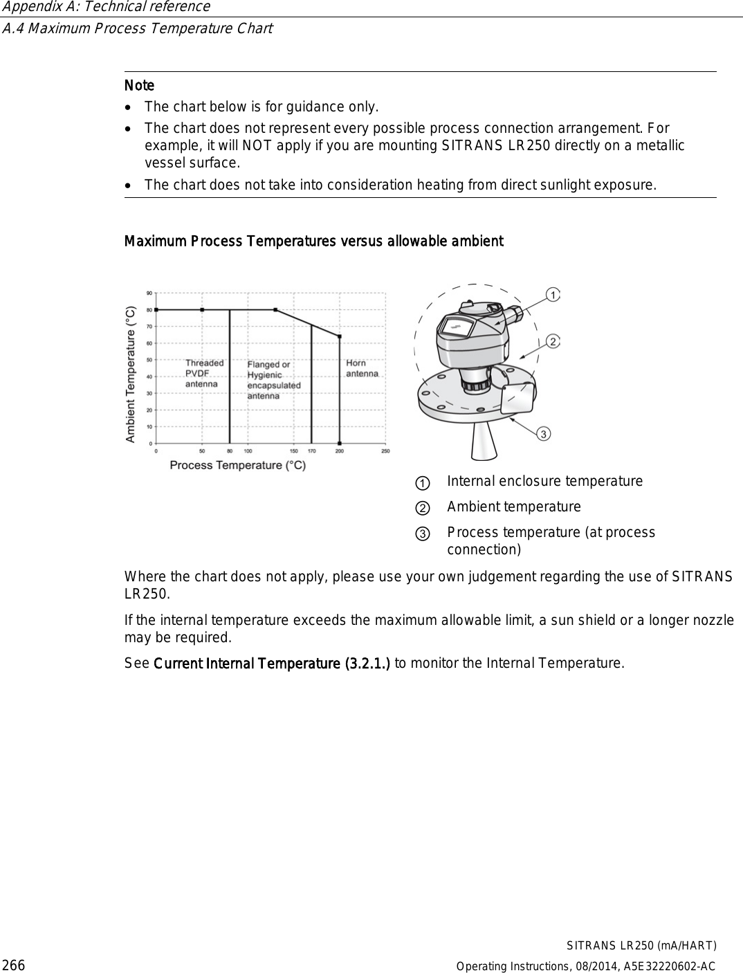
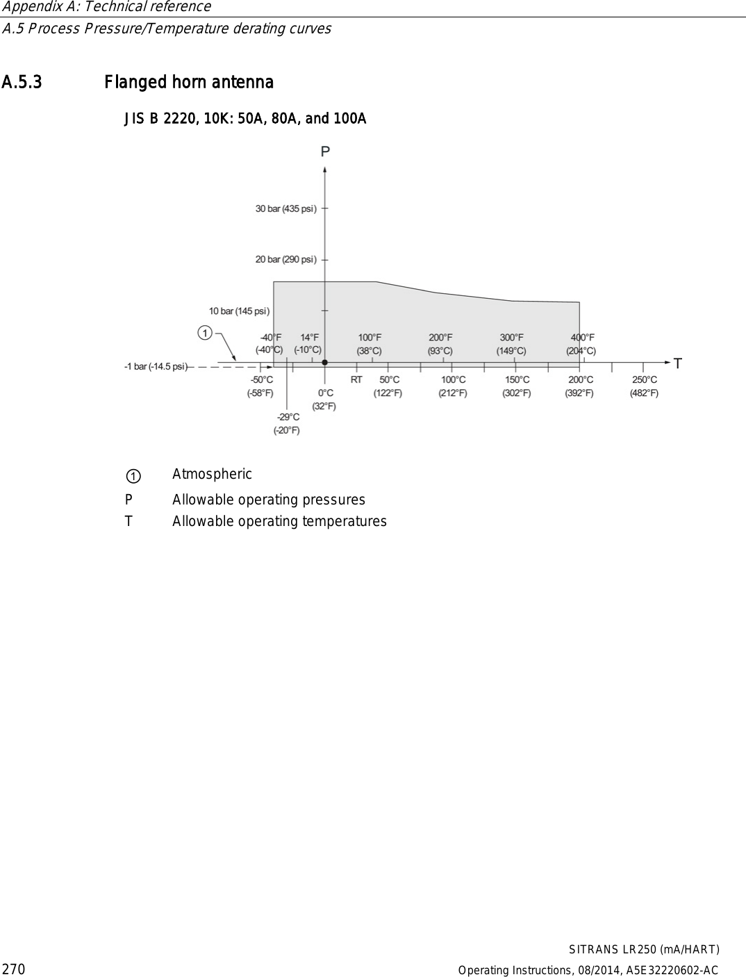
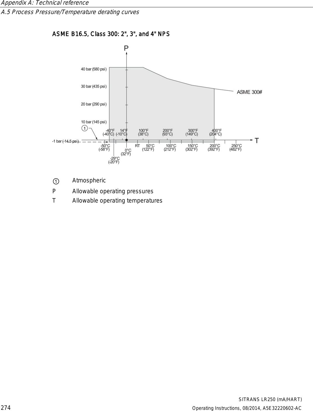
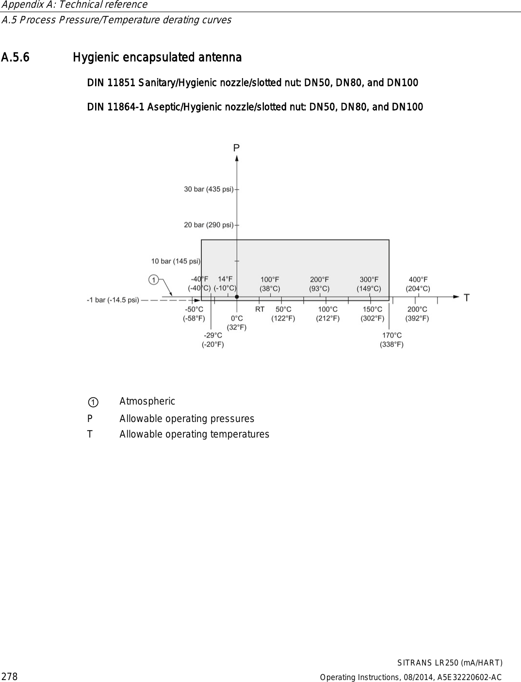
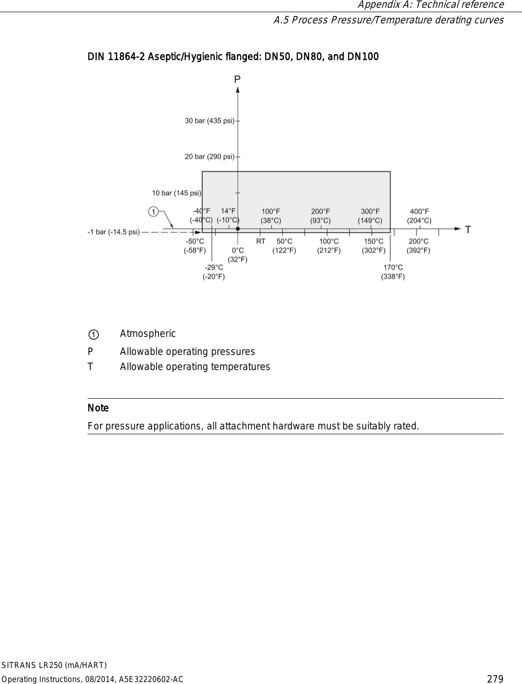
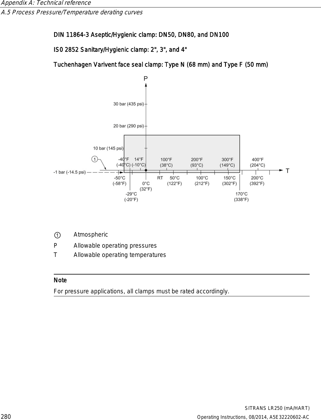
![Appendix A: Technical reference A.5 Process Pressure/Temperature derating curves SITRANS LR250 (mA/HART) Operating Instructions, 08/2014, A5E32220602-AC 269 A.5.2 Horn antenna 1.5", 2" and 3" [NPT, G (BSPP), R (BSPT)] Threaded Versions ① Atmospheric P Allowable operating pressures T Allowable operating temperatures](https://usermanual.wiki/Siemens-Canada-Siemens-Milltronics-Process-Instruments/LR250.User-Manual-2/User-Guide-2277917-Page-87.png)