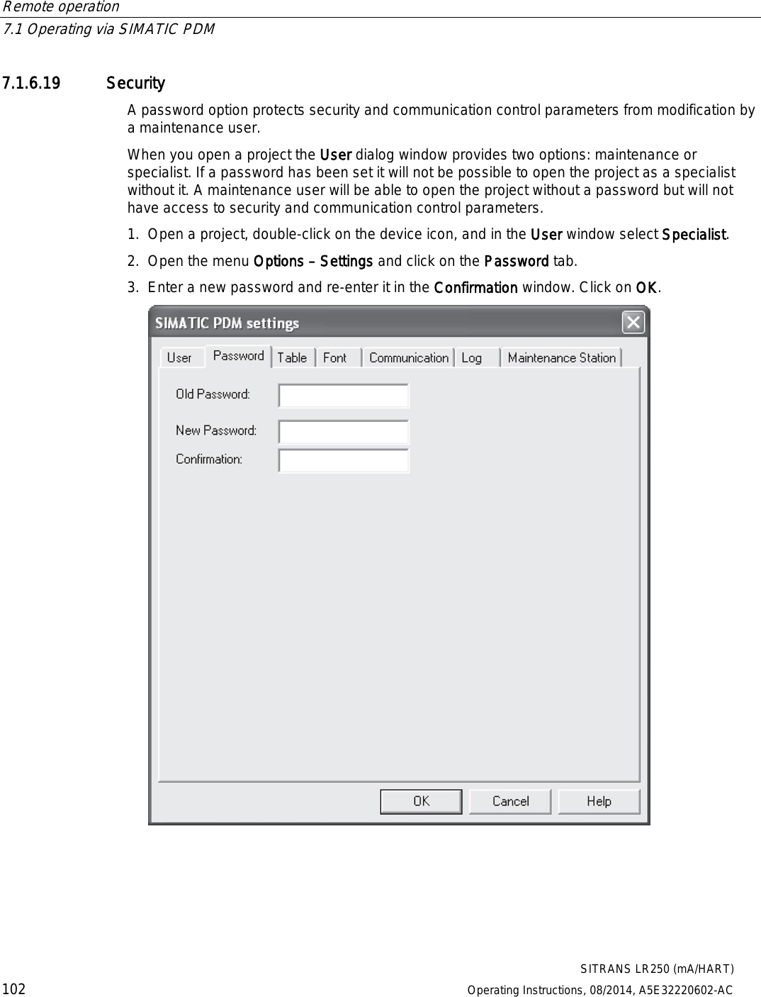
Siemens Canada Siemens Milltronics Process Instruments LR250 SITRANS LR 250 TANK LEVEL PROBING RADAR User Manual SITRANS LR250 mA HART
Siemens Canada Ltd. - Siemens Milltronics Process Instruments SITRANS LR 250 TANK LEVEL PROBING RADAR SITRANS LR250 mA HART
Contents
User Manual 1
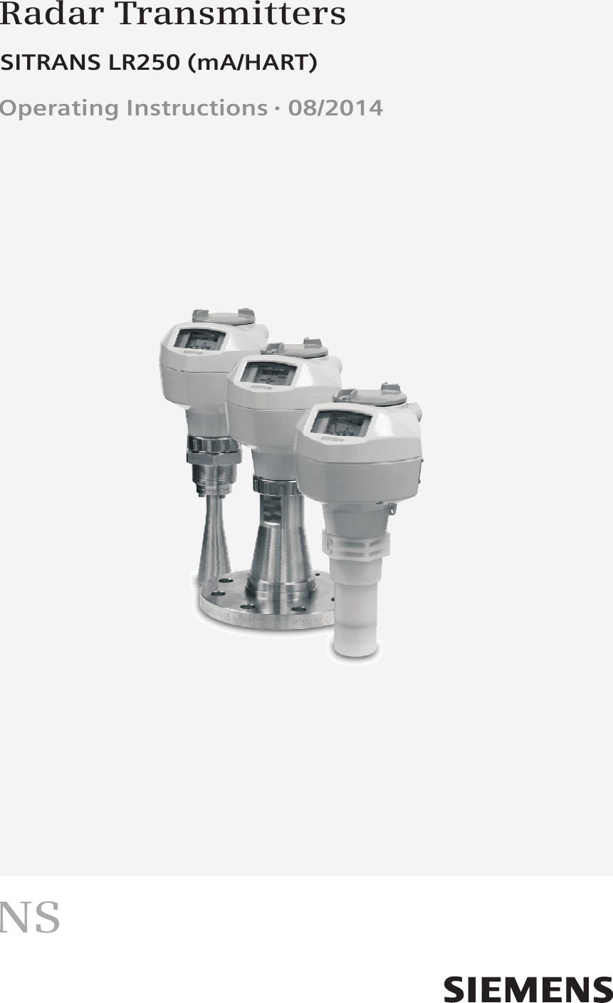
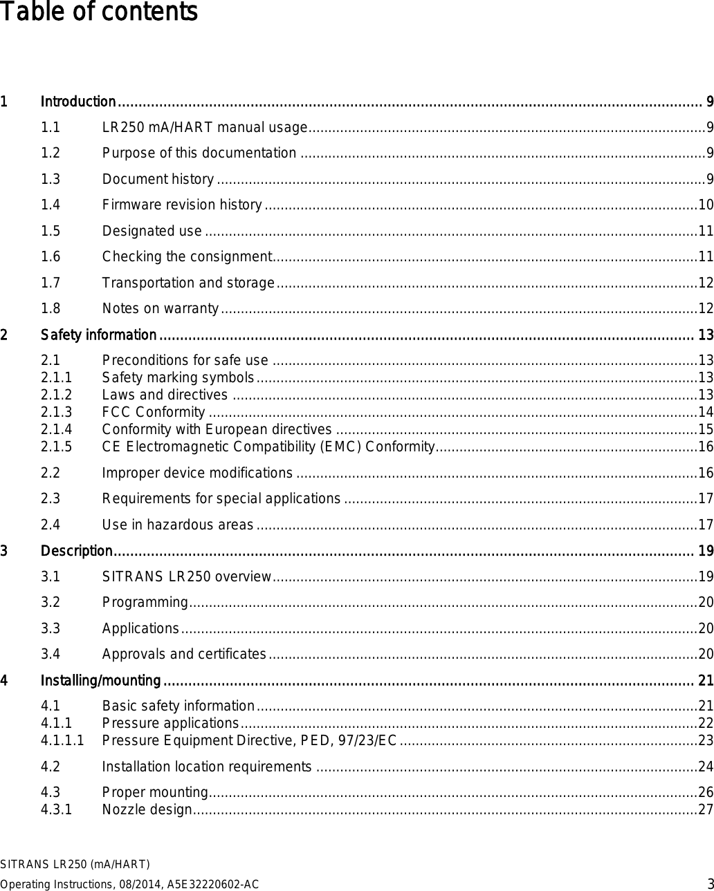
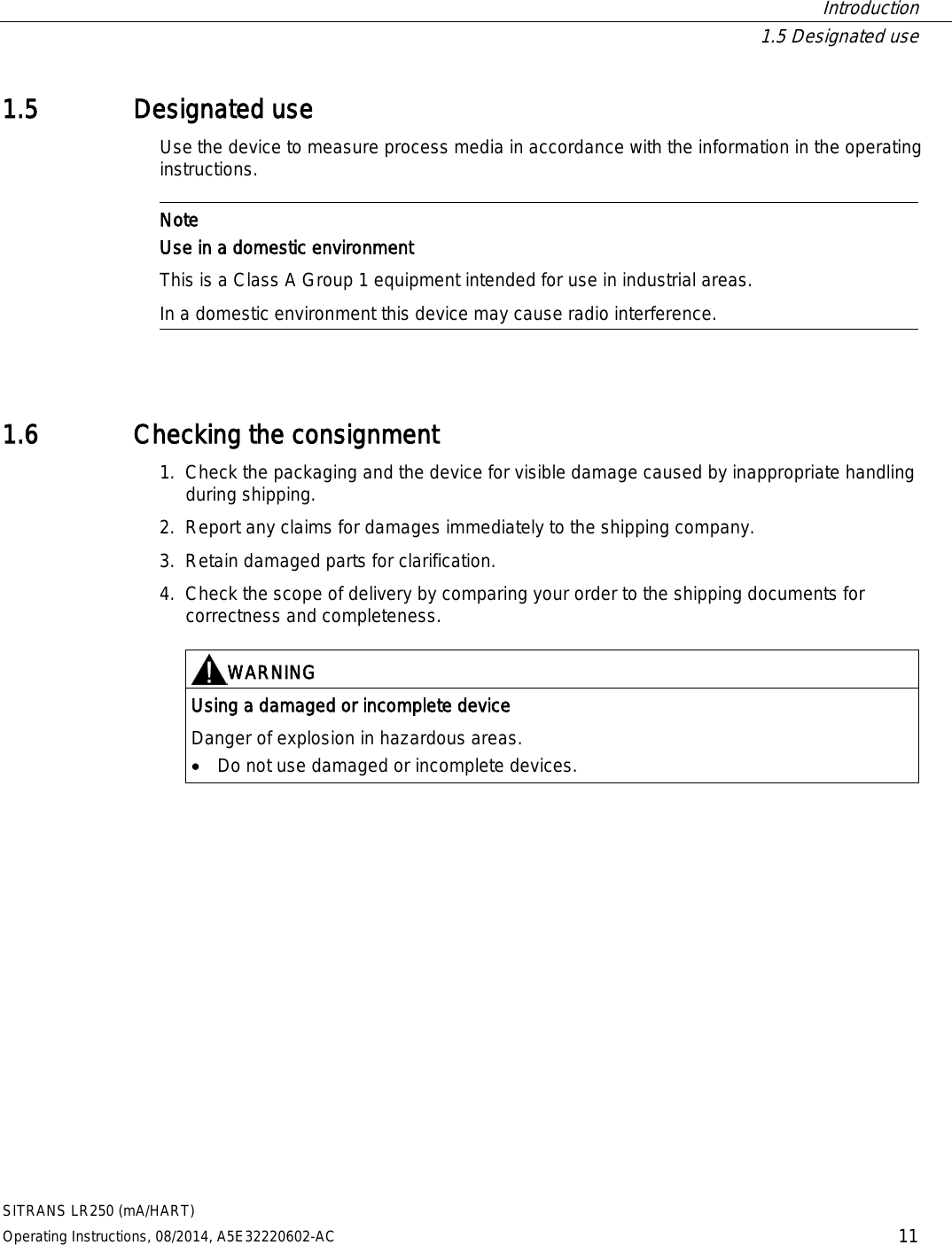
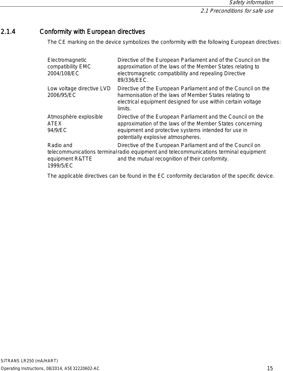

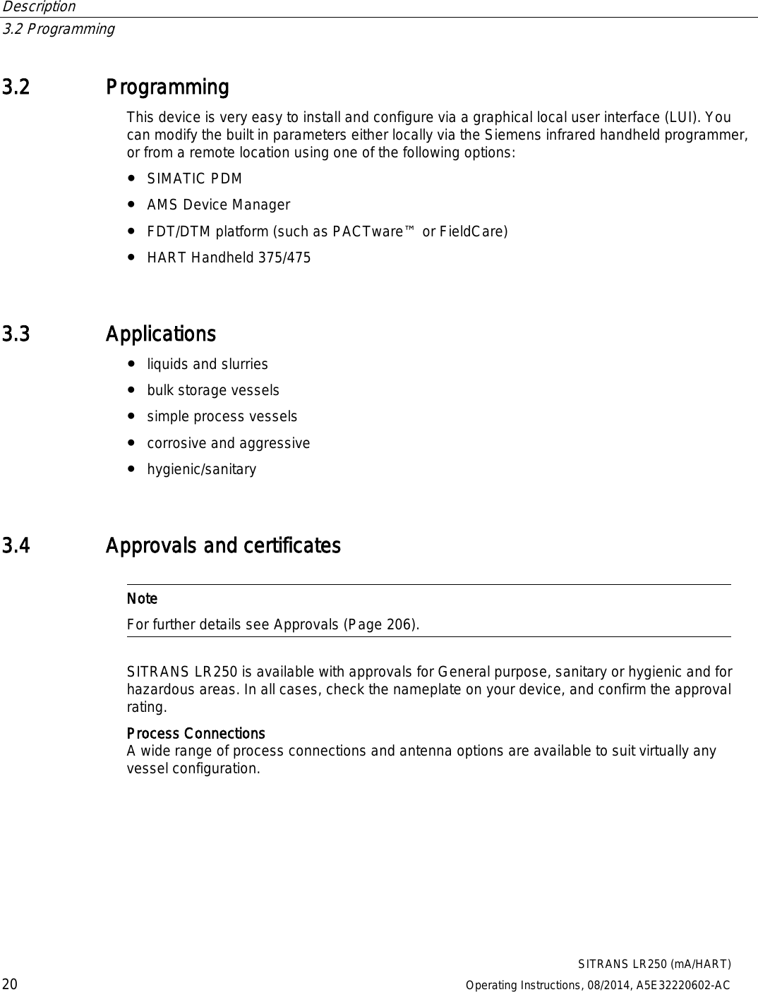
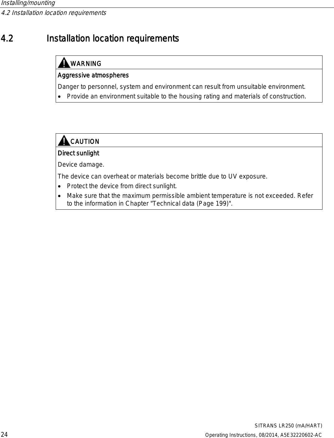
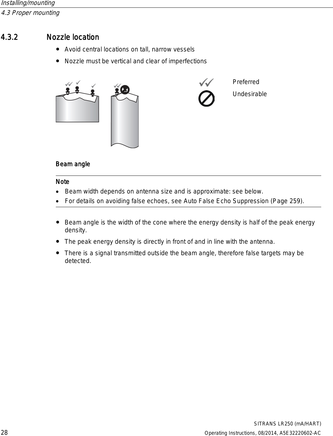
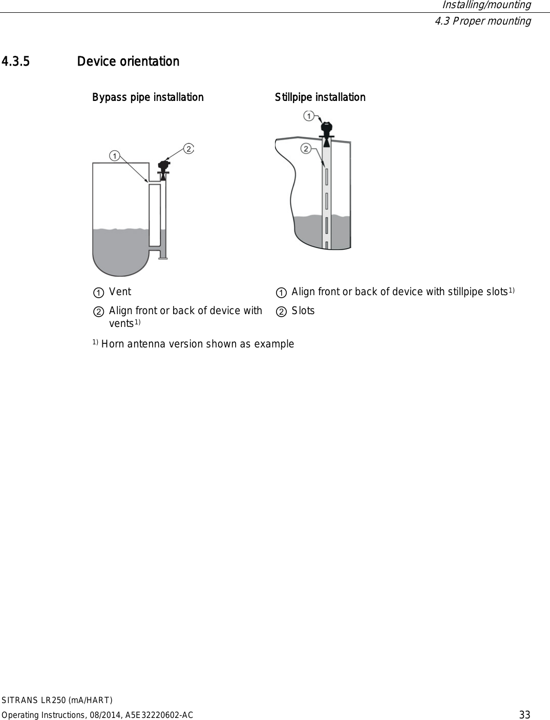
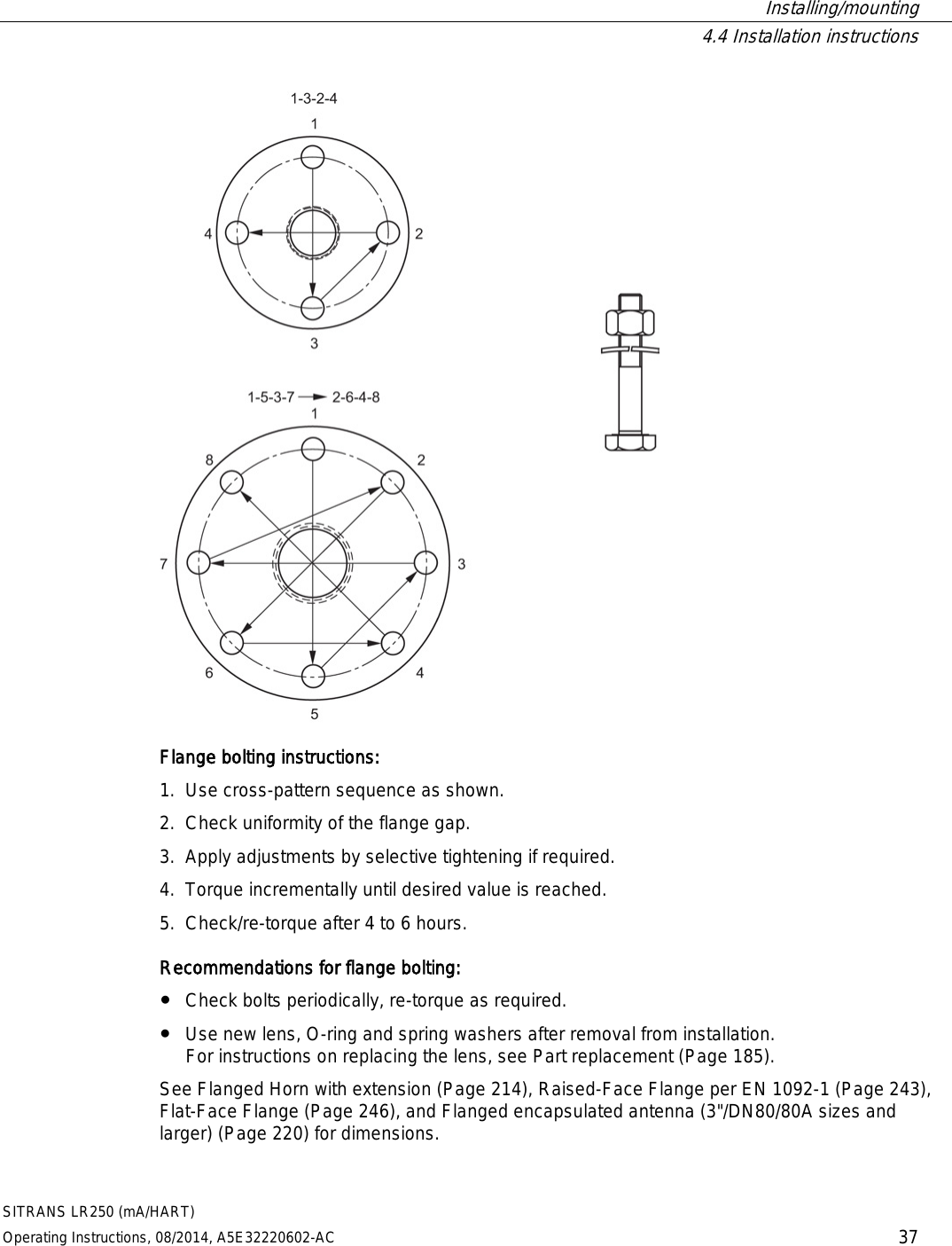
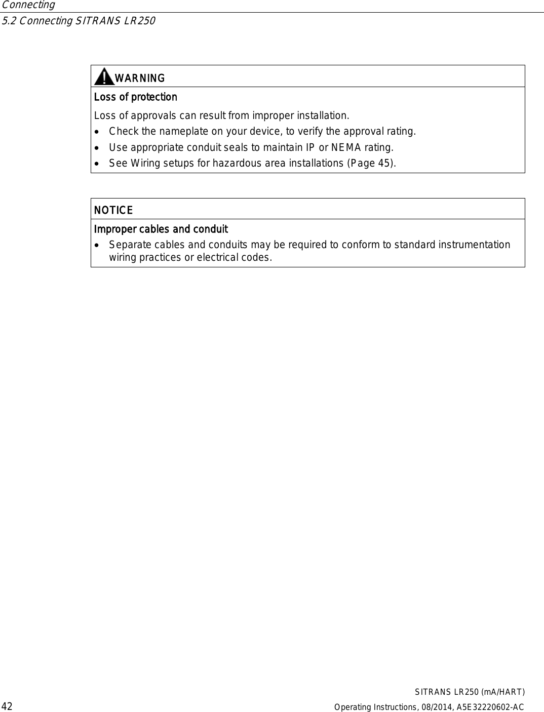
![Installing/mounting 4.3 Proper mounting SITRANS LR250 (mA/HART) 30 Operating Instructions, 08/2014, A5E32220602-AC Emission cone type and beam angle Antenna type Antenna size Beam angle Horn 1.5" 19° 2" 15° 3" 10° 4" 8° Threaded PVDF 19° Process connection size Process connection type Flanged encapsulated 2" Class 150 ASME B16.5 12.8° 3, 4, 6" Class 150 ASME B16.5 9.6° 50A 10K JIS B 2220 12.8° 80A/100A/150A 10K JIS B 2220 9.6° DN50 PN10/16 EN1092-1 12.8° DN80/DN100/DN150 PN10/16 EN1092-1 9.6° Hygienic encapsulated 2" Sanitary Clamp according to ISO 2852 12.8° 3, 4" 9.6° DN50 Aseptic/Hygienic nozzle/slotted nut according to DIN 11864-1 [Form A] 12.8° DN80/DN100 9.6° DN50 Aseptic/Hygienic flanged according to DIN 11864-2 [Form A] 12.8° DN80/DN100 9.6° DN50 Aseptic/Hygienic Clamp according to DIN 11864-3 [Form A] 12.8° DN80/DN100 9.6° DN50 Hygienic nozzle/slotted nut according to DIN 11851 12.8° DN80/DN100 9.6° Type F (50 mm) and Type N (68 mm) Tuchenhagen Varivent 12.8° Emission cone ● Keep emission cone free of interference from obstructions such as ladders, pipes, I-beams, or filling streams. Access for programming ● Provide easy access for viewing the display and programming via the handheld programmer.](https://usermanual.wiki/Siemens-Canada-Siemens-Milltronics-Process-Instruments/LR250.User-Manual-1/User-Guide-2277916-Page-32.png)
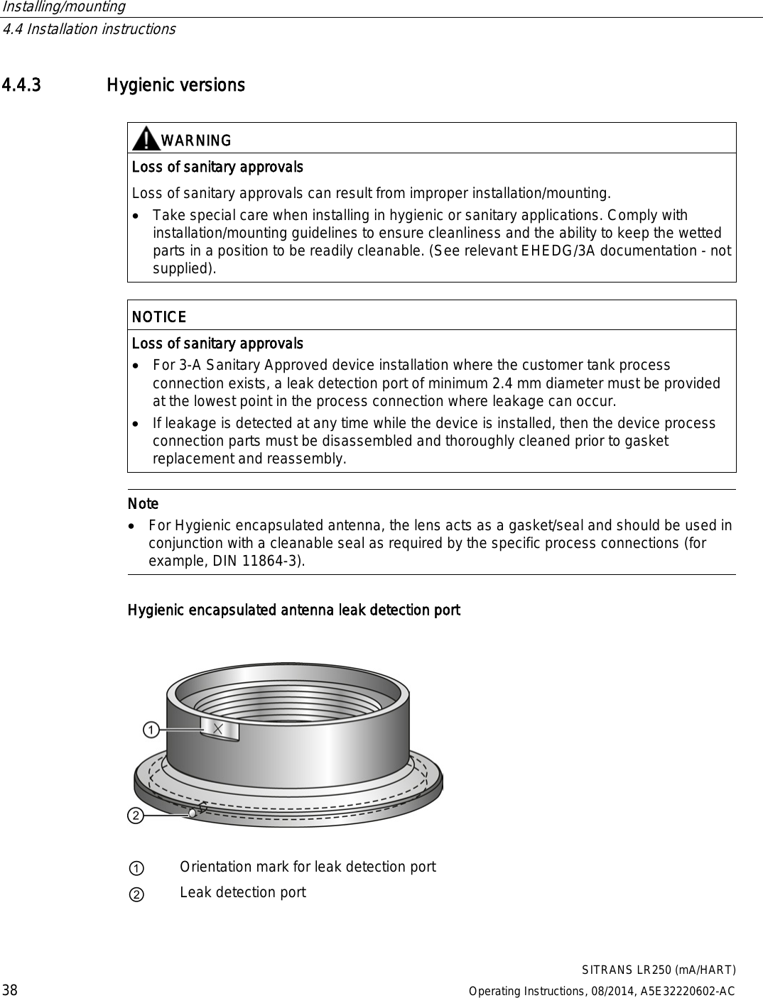

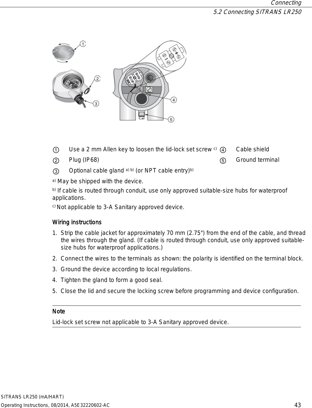
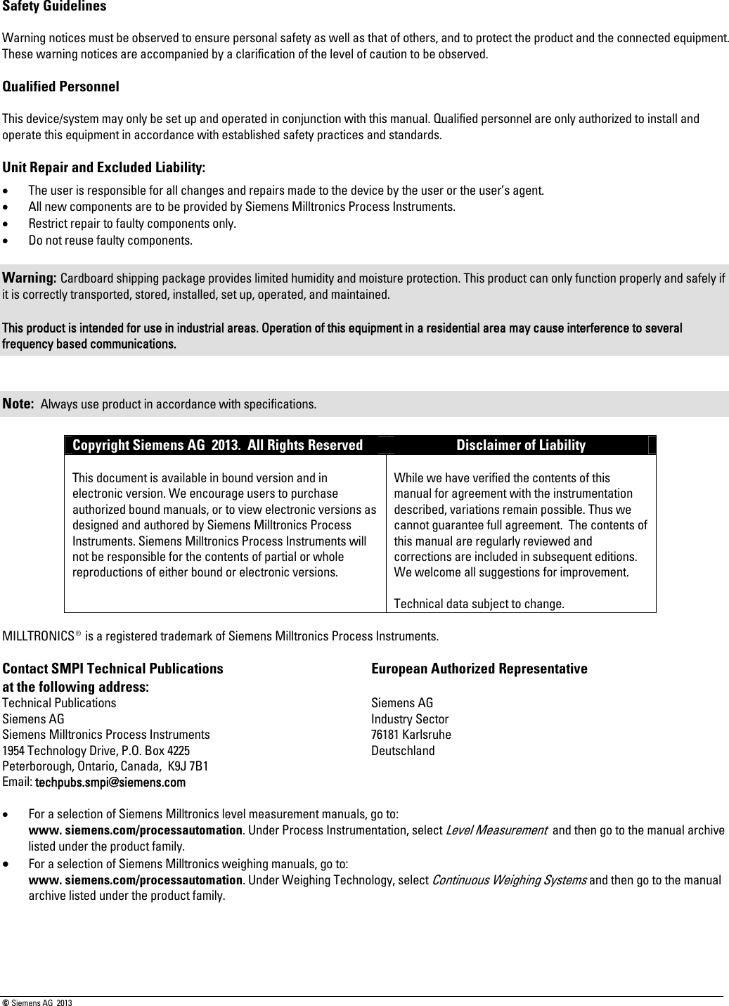
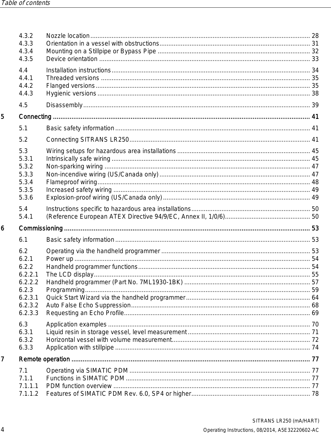
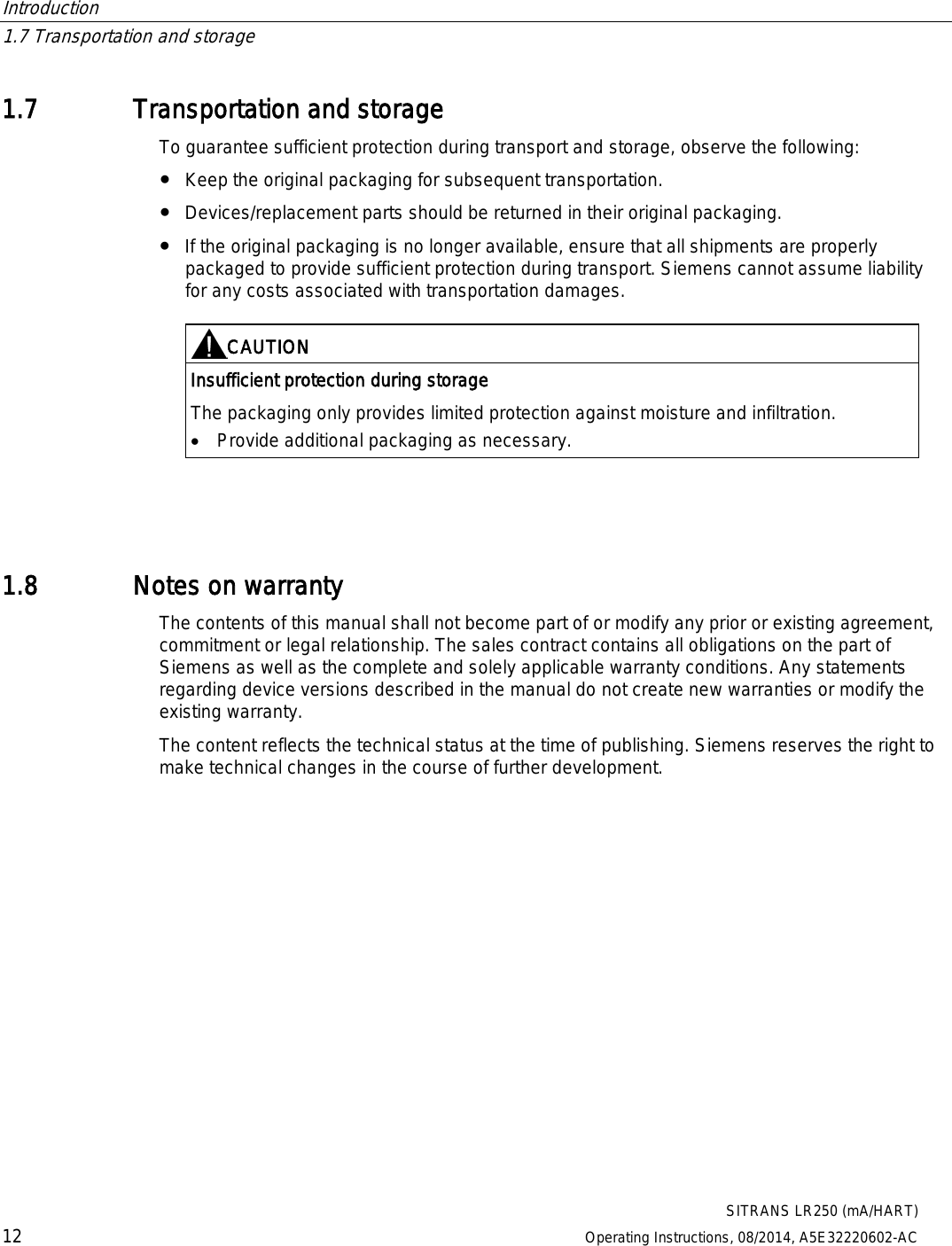
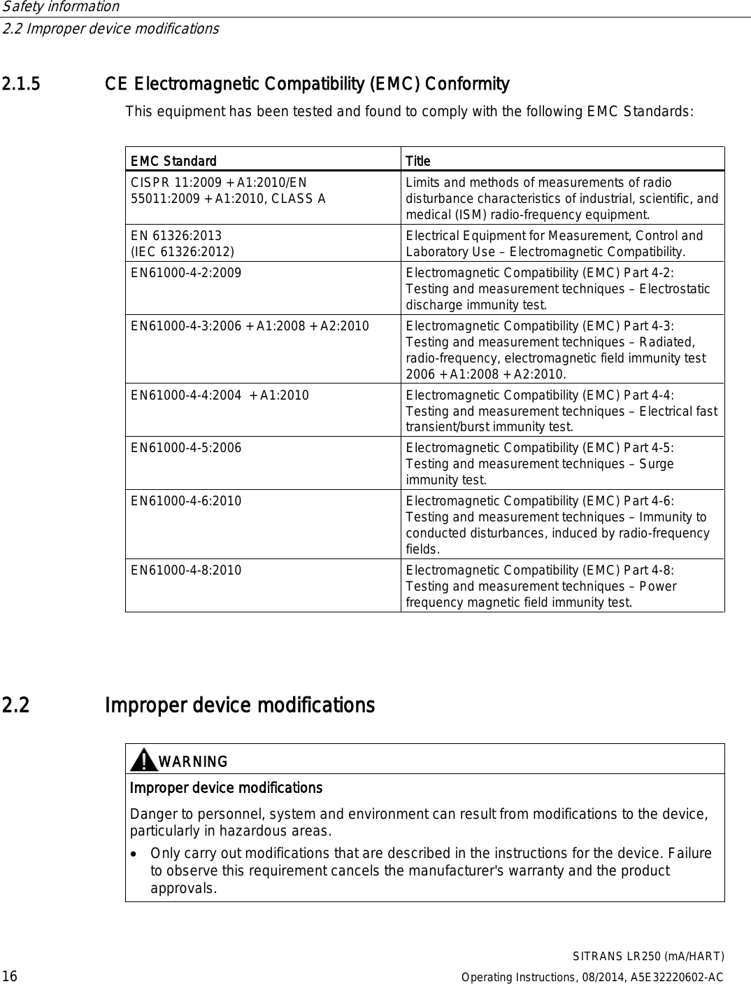
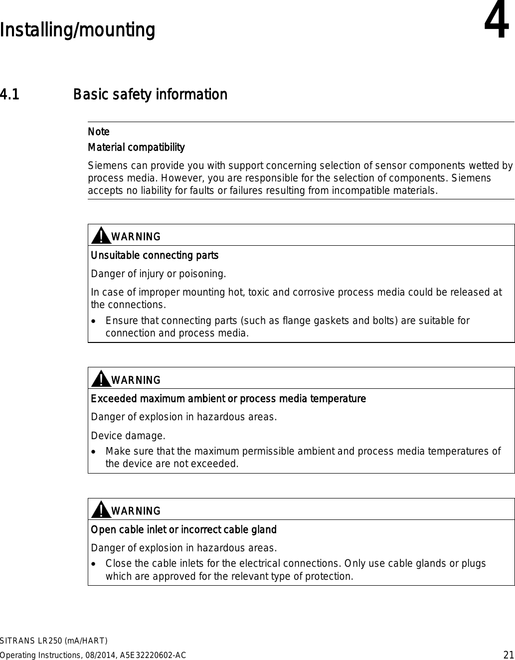
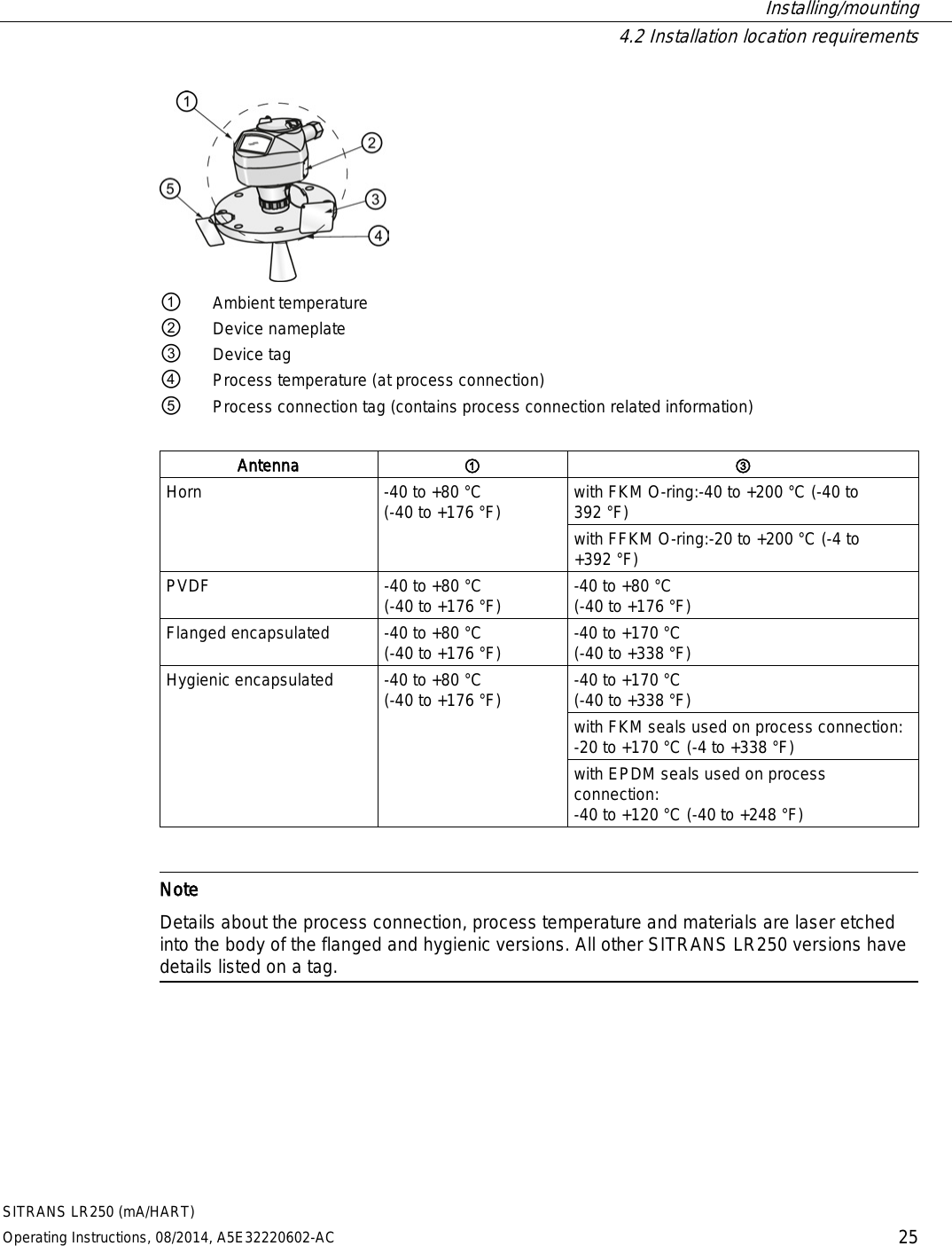
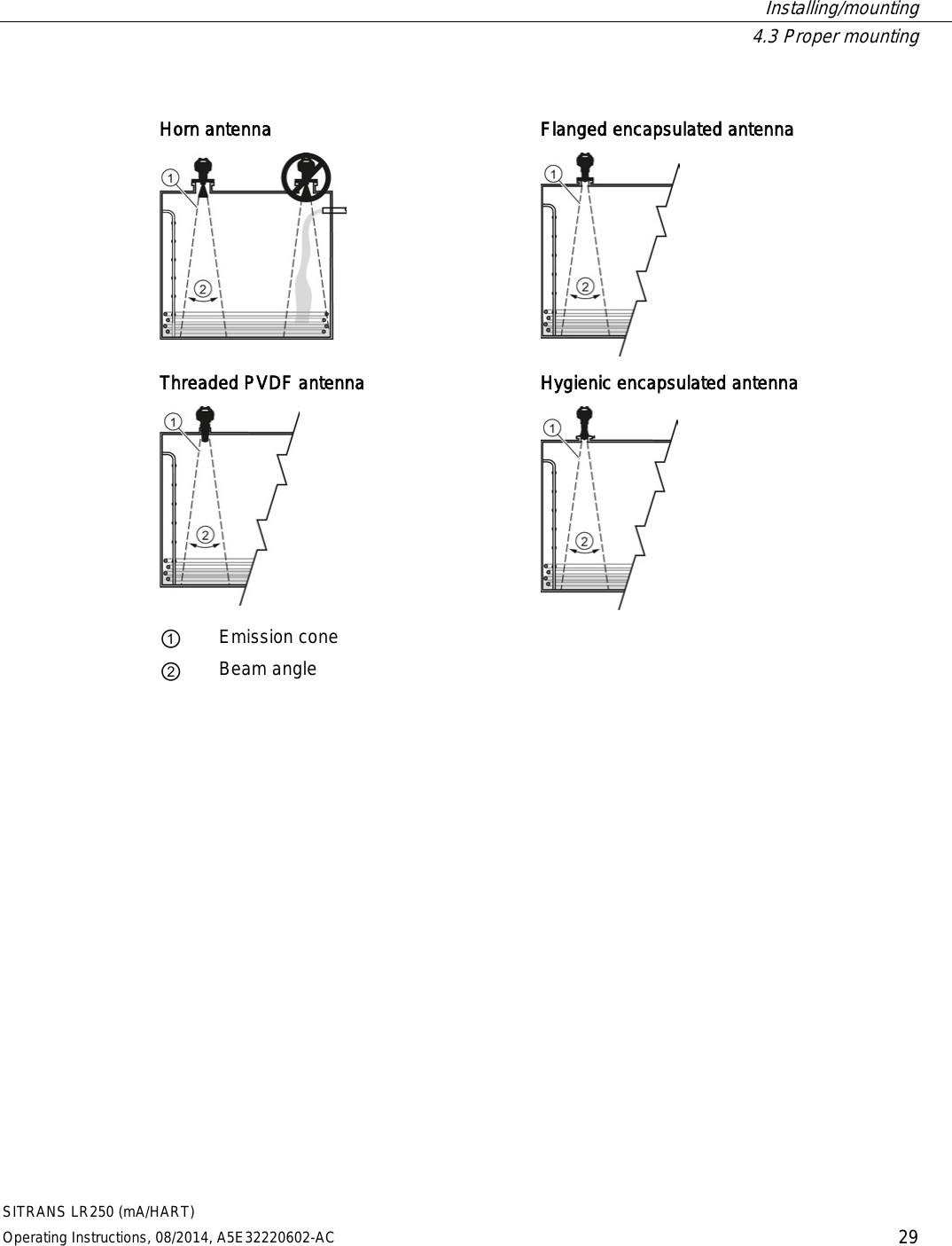
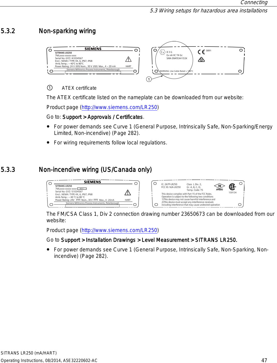
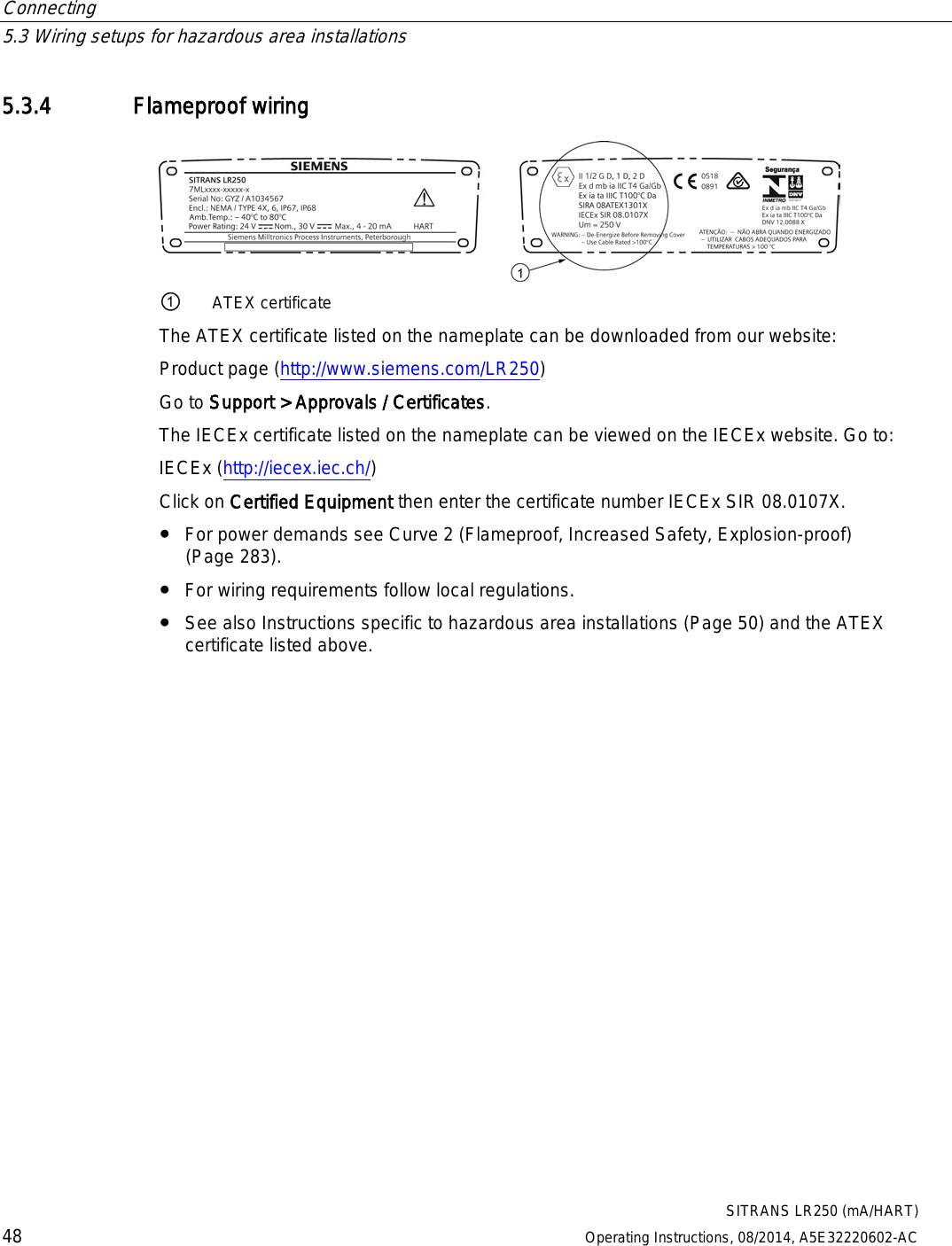
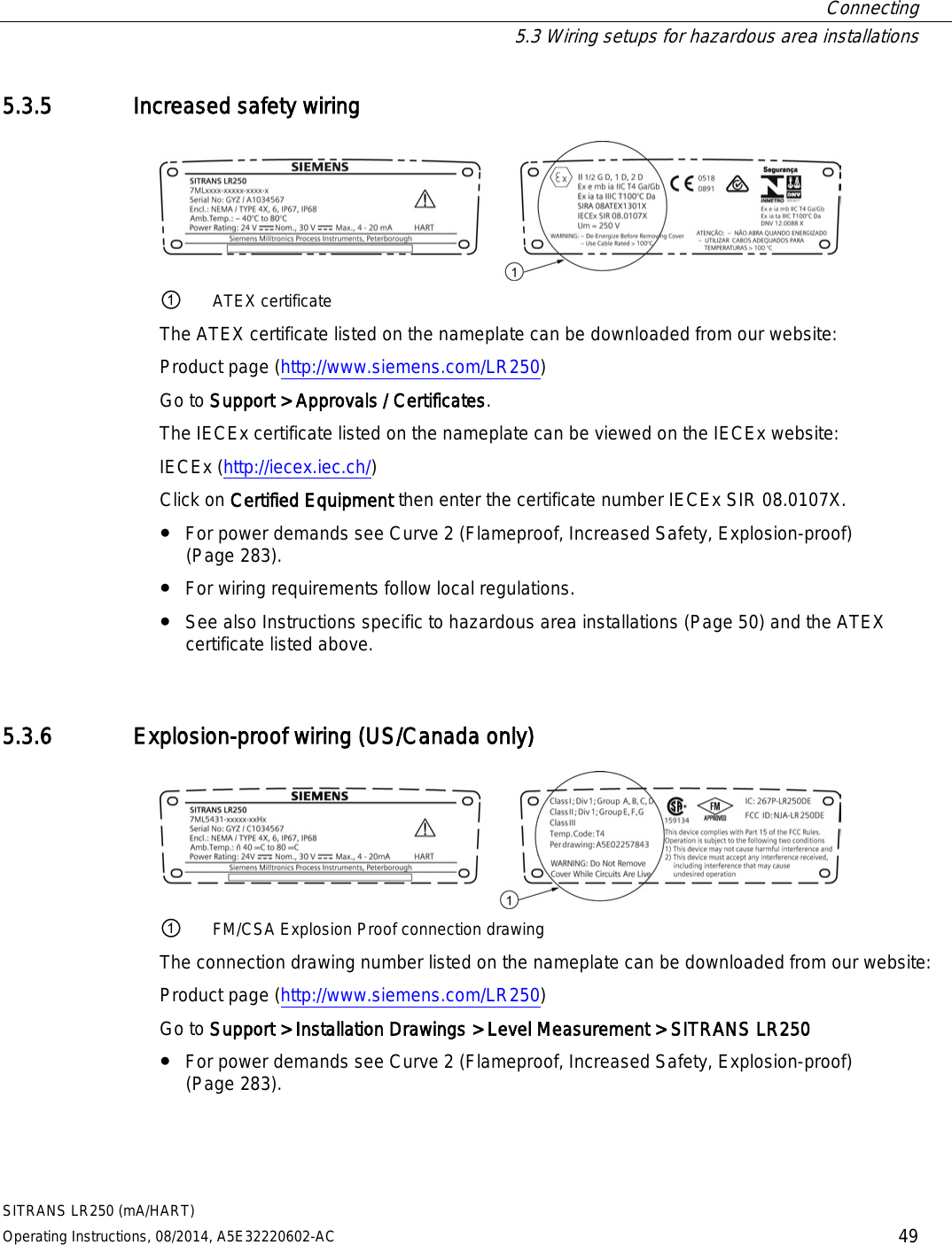
![Connecting 5.2 Connecting SITRANS LR250 SITRANS LR250 (mA/HART) 44 Operating Instructions, 08/2014, A5E32220602-AC Connecting HART Typical PLC/mA configuration with HART ① Power supply ④ Active PLC ② SITRANS LR250 ⑤ HART modem ③ R = 250 Ω ⑥ HART communicator Note • Depending on the system design, the power supply may be separate from the PLC, or integral to it. • HART resistance (total loop resistance, that is, cable resistance plus 250 Ohm [resistor]) must be limited according to the allowable operating area as shown in either Curve 1 (Page 282) (General Purpose, Intrinsically Safe, Non-Sparking, Non-incendive) or Curve 2 (Page 283) (Flameproof, Increased Safety, Explosion-proof).](https://usermanual.wiki/Siemens-Canada-Siemens-Milltronics-Process-Instruments/LR250.User-Manual-1/User-Guide-2277916-Page-46.png)
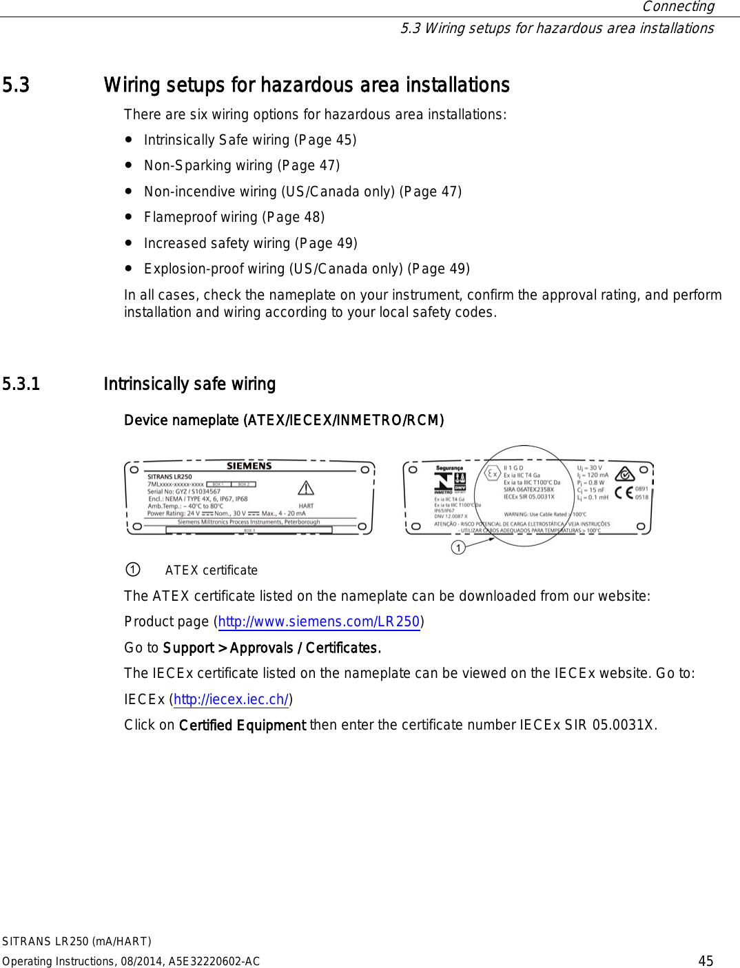

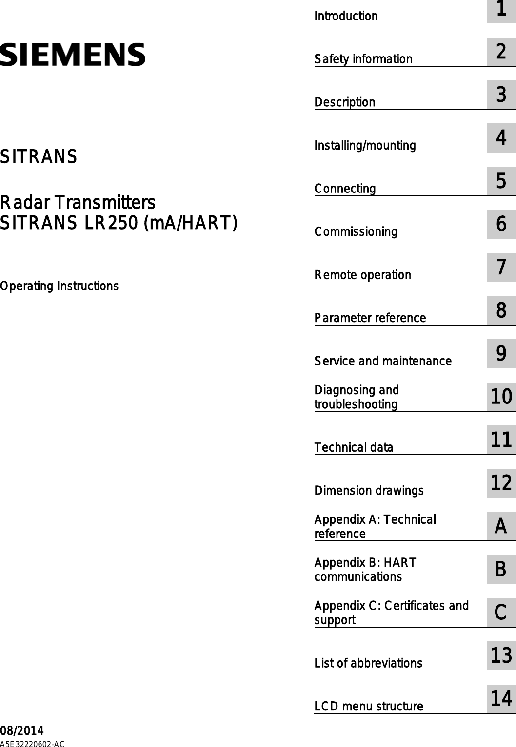
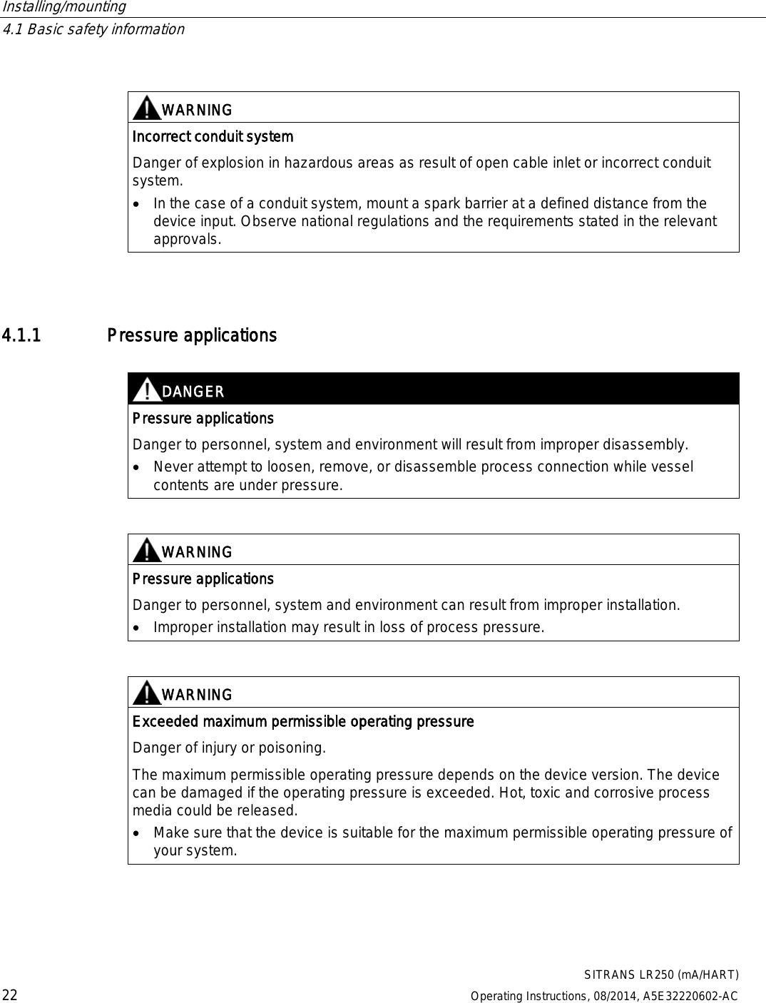
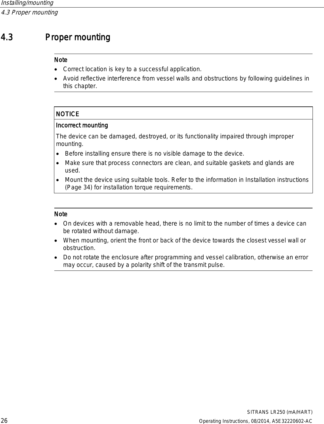
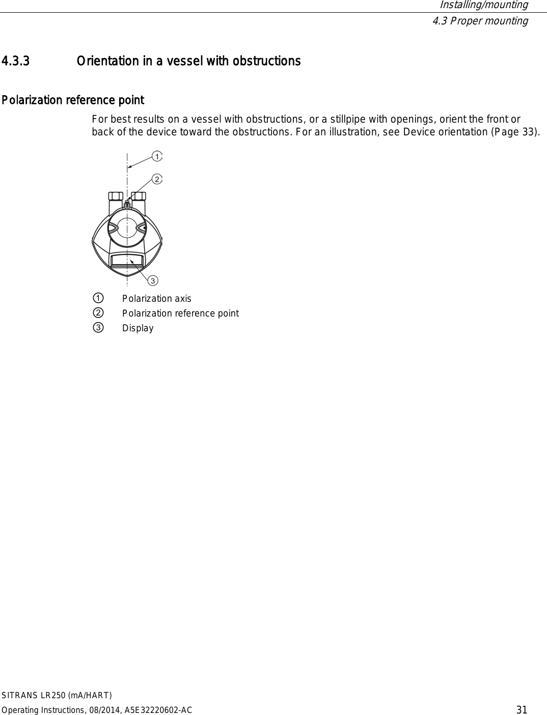
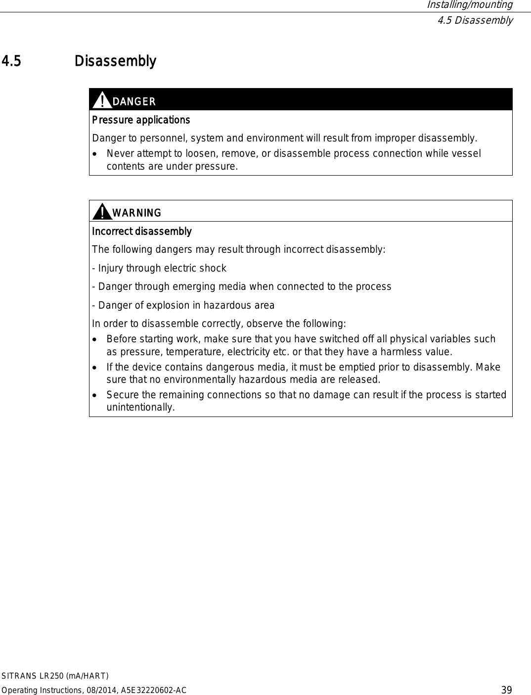
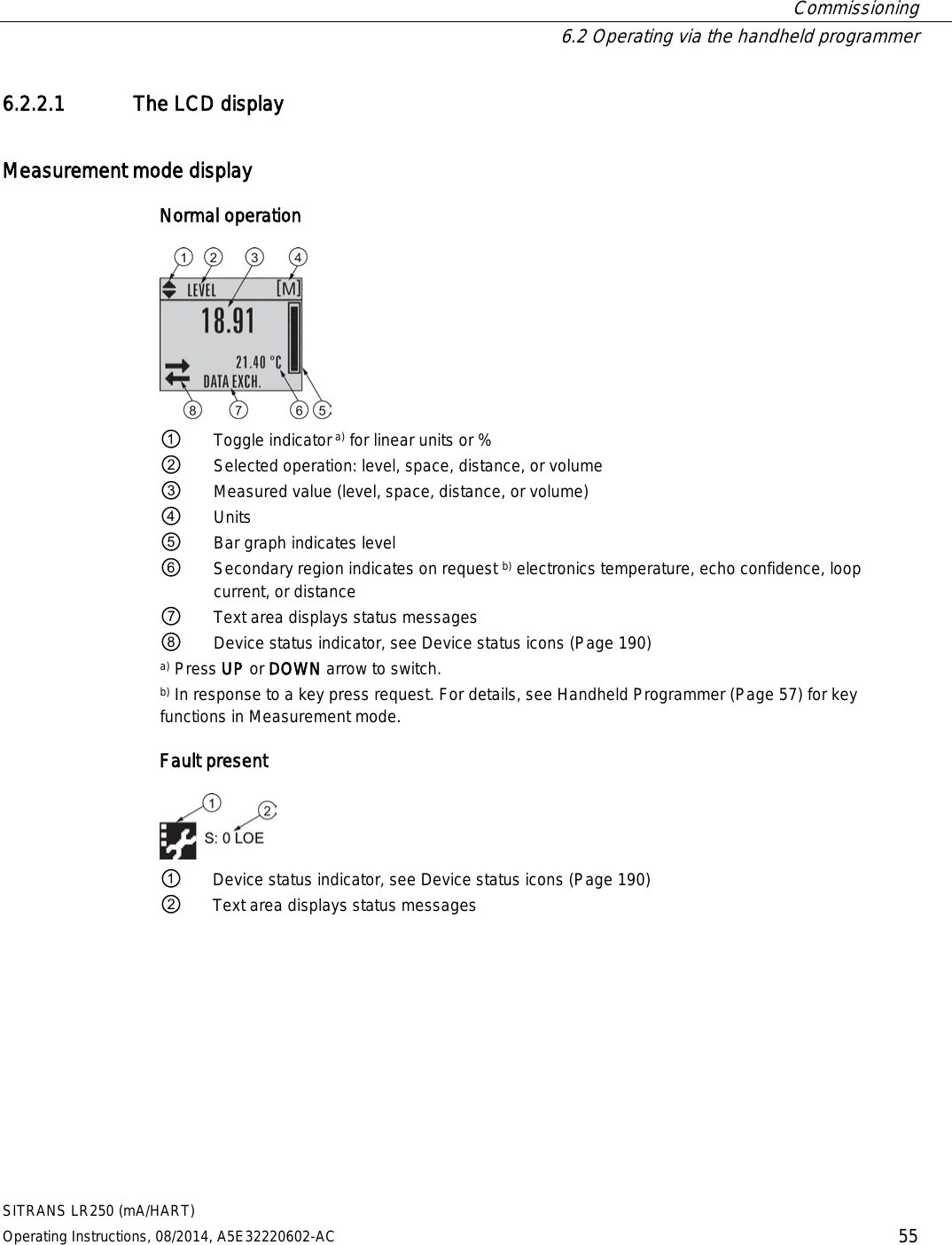
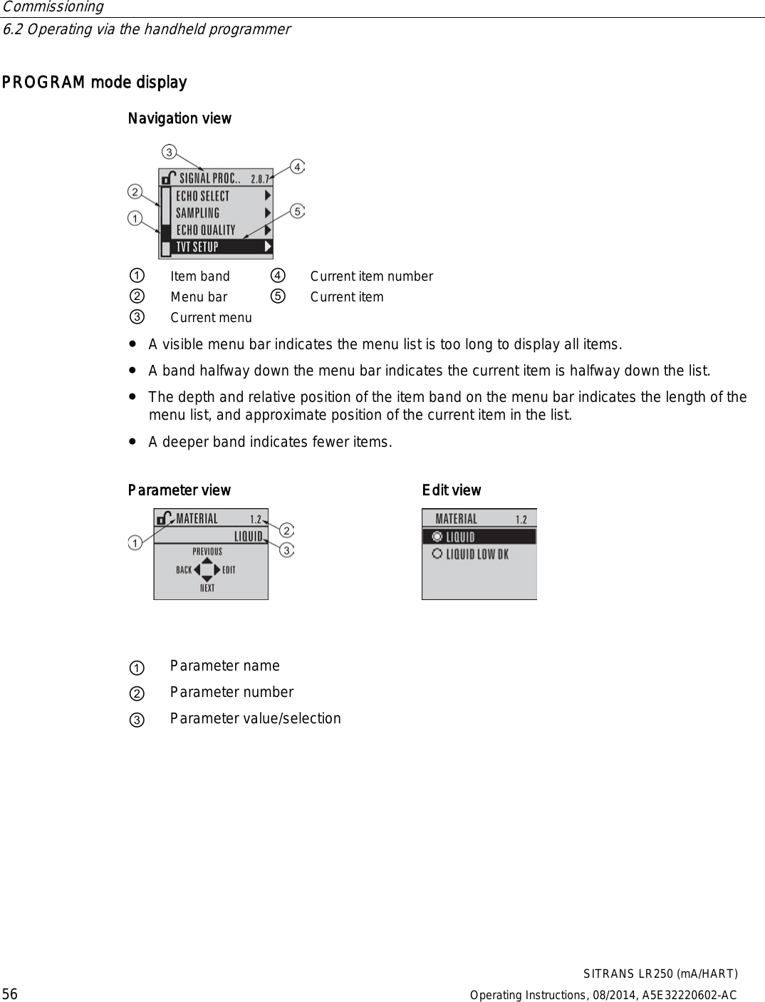
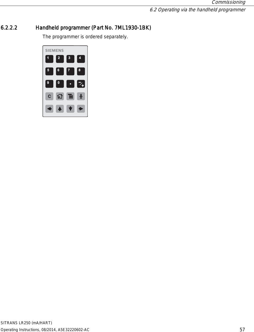
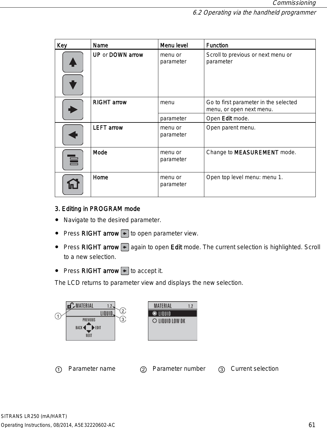
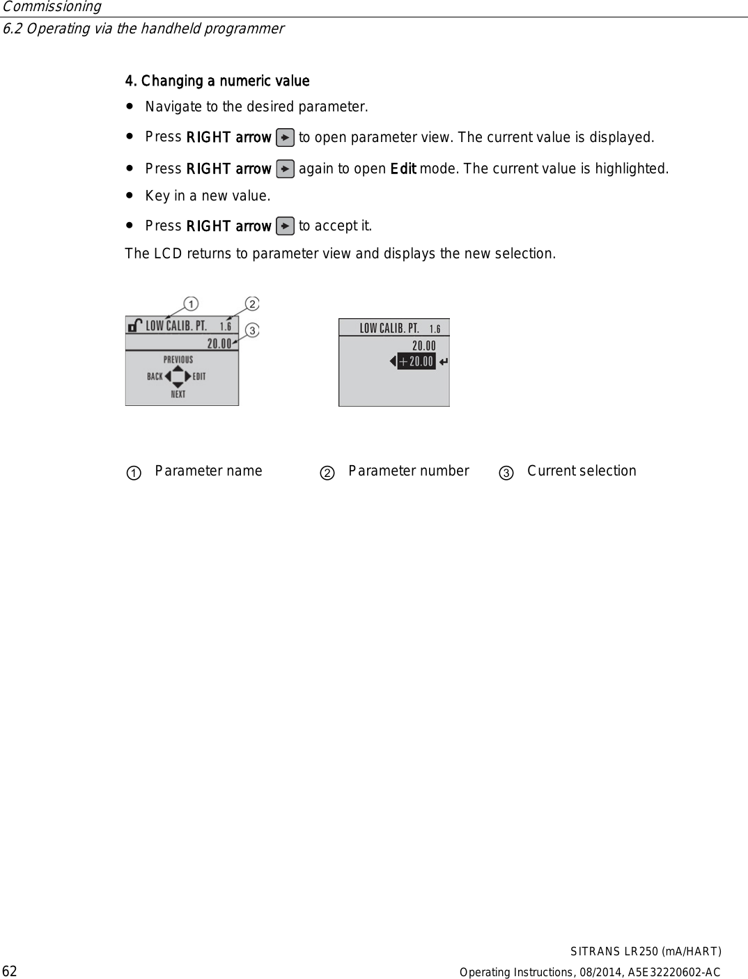
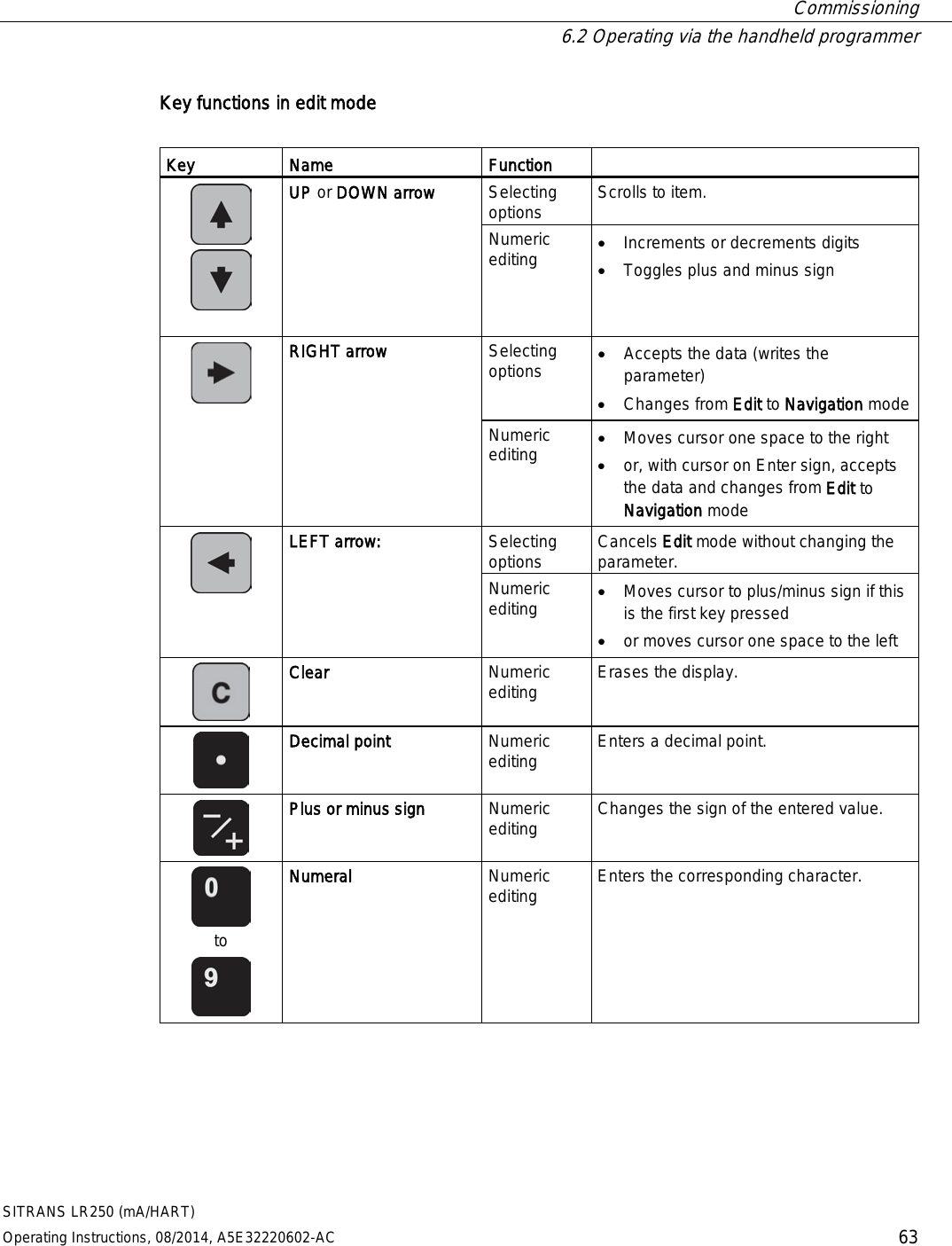
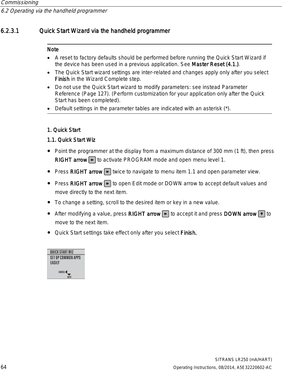
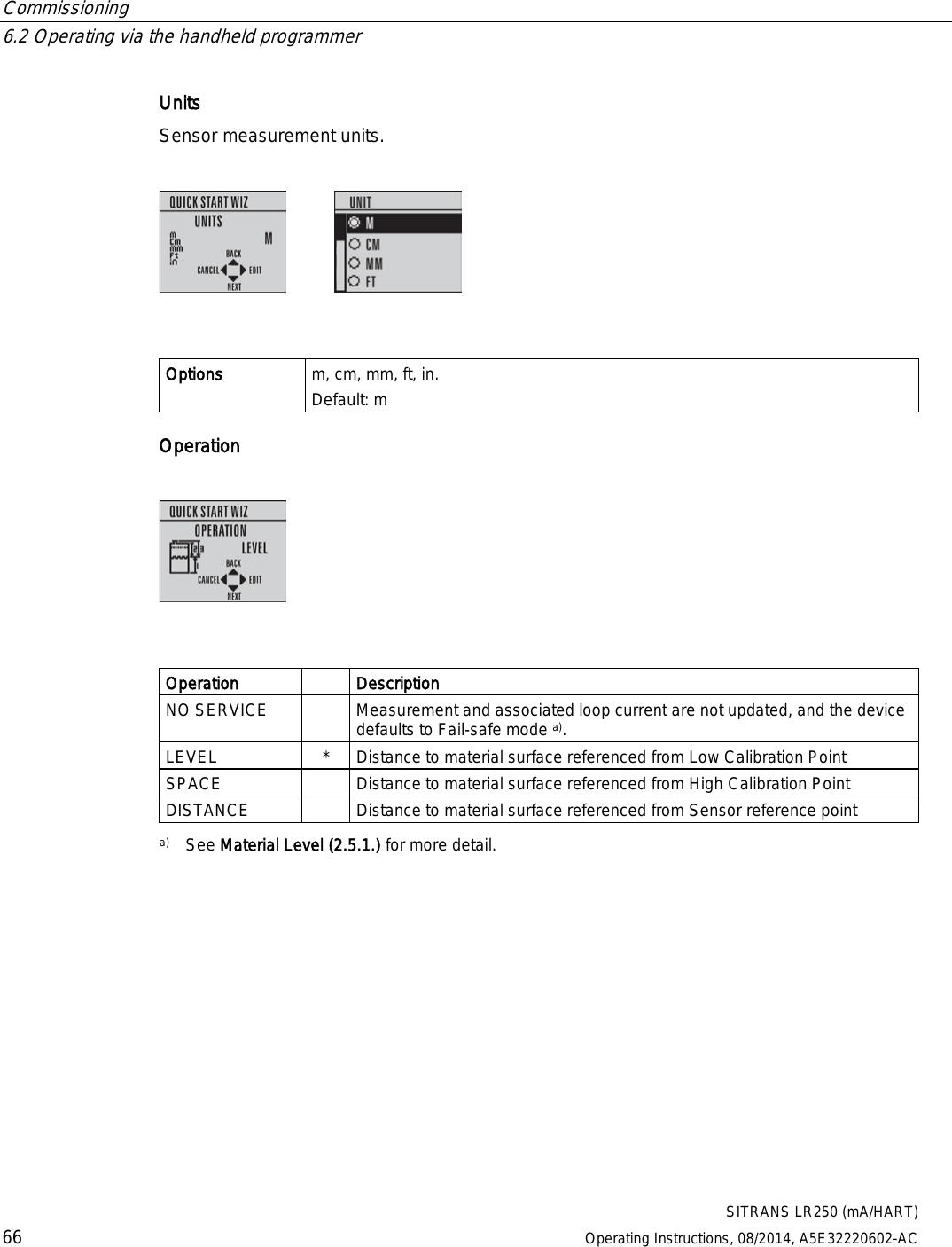
![Commissioning 6.2 Operating via the handheld programmer SITRANS LR250 (mA/HART) 54 Operating Instructions, 08/2014, A5E32220602-AC 6.2.1 Power up Power up the device. A transition screen showing first the Siemens logo and then the current firmware revision is displayed while the first measurement is being processed. The first time the device is configured, you will be prompted to select a language (English, German, French, or Spanish). To change the language again, see Language (7.). Press Mode to toggle between Measurement and Program mode. 6.2.2 Handheld programmer functions The radar device carries out its level measurement tasks according to settings made via parameters. The settings can be modified locally via the Local User Interface (LUI) which consists of an LCD display and a handheld programmer. A Quick Start Wizard provides an easy step-by-step procedure to configure the device for a simple application. Access the wizards: ● locally [see Quick Start Wizard via the handheld programmer (Page 64)] ● or from a remote location [see Quick Start Wizard via SIMATIC PDM (Page 81), or Quick Start Wizard via AMS Device Manager (Page 107)] For more complex setups see Application Examples (Page 70), and for the complete range of parameters see Parameter Reference (Page 127).](https://usermanual.wiki/Siemens-Canada-Siemens-Milltronics-Process-Instruments/LR250.User-Manual-1/User-Guide-2277916-Page-56.png)
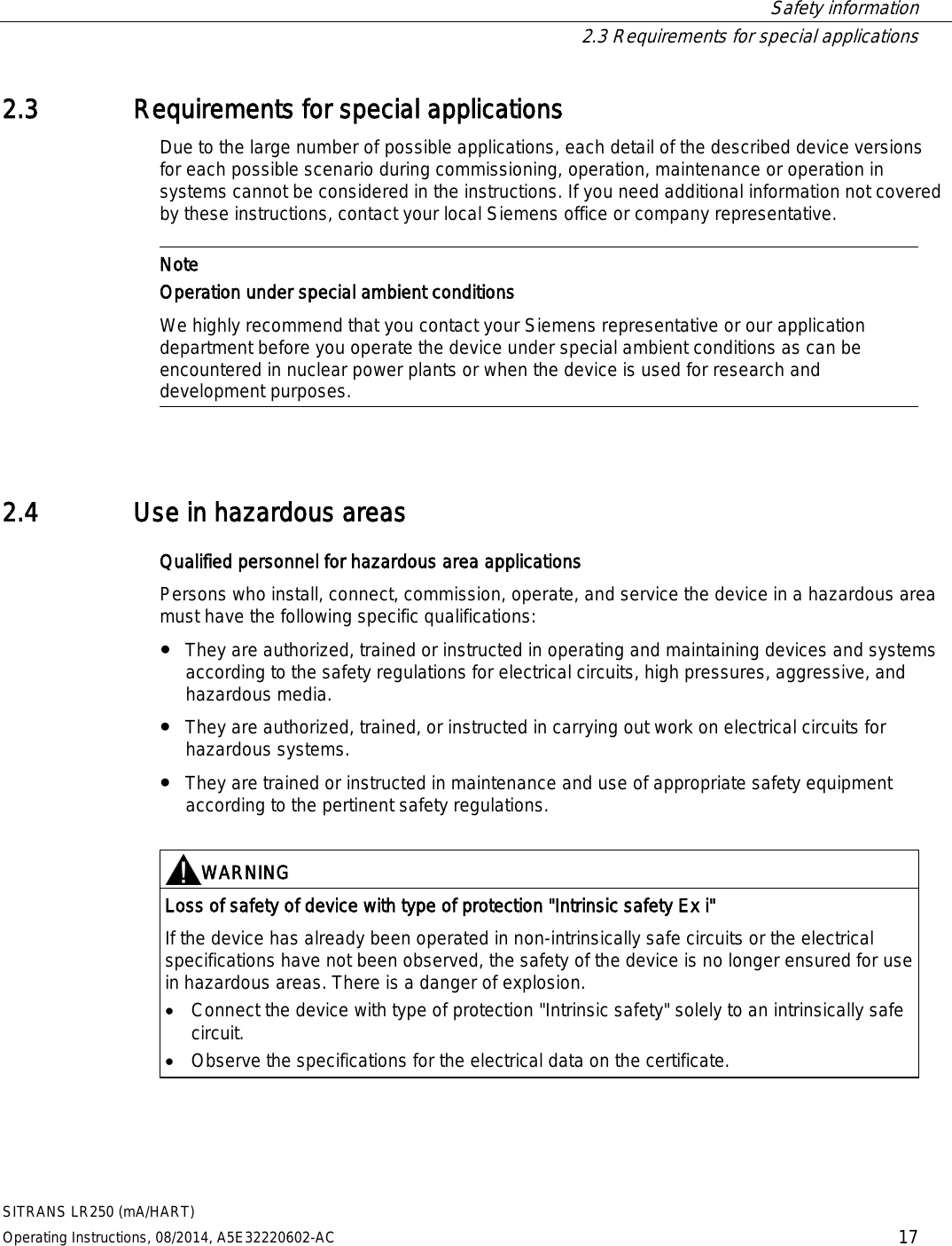
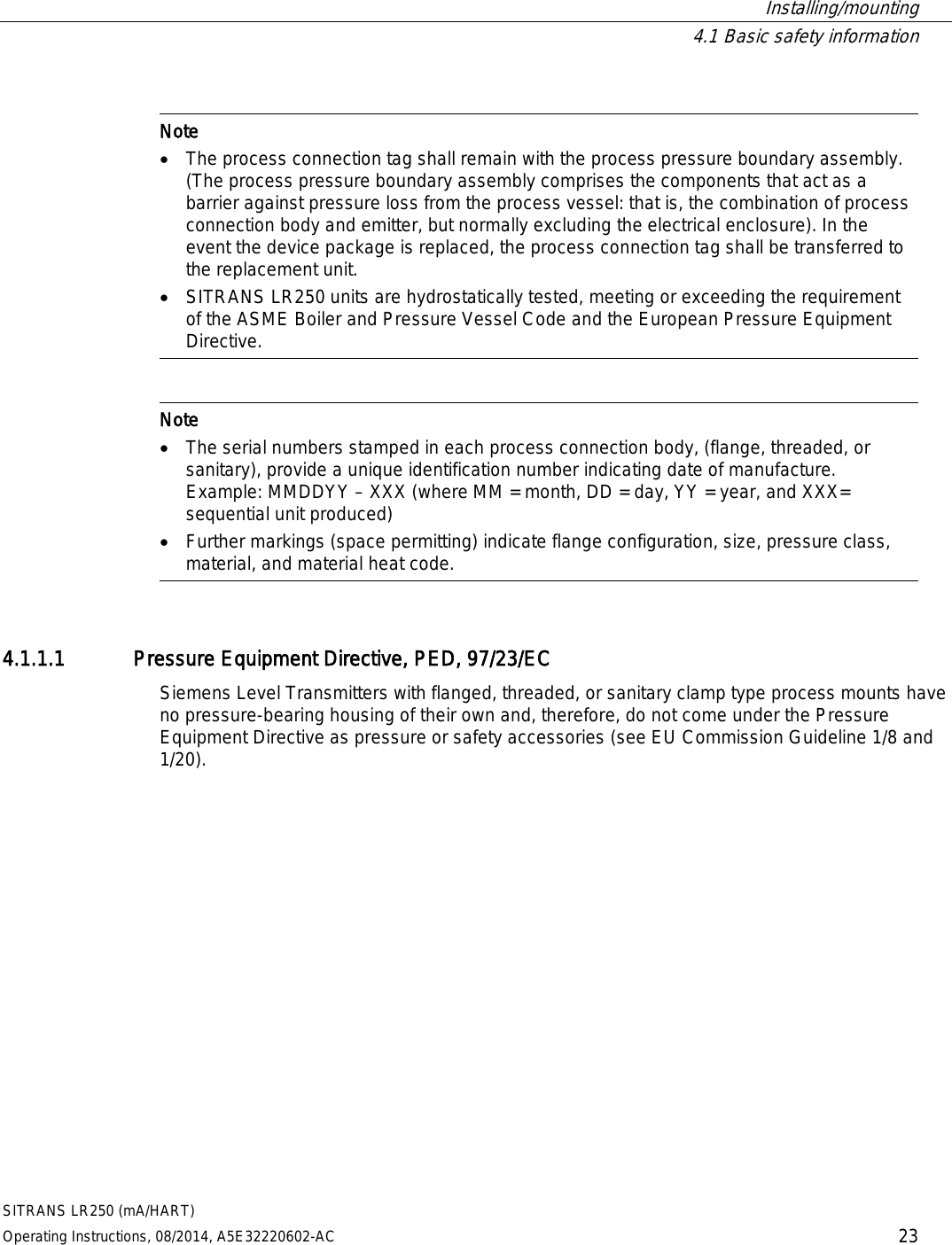
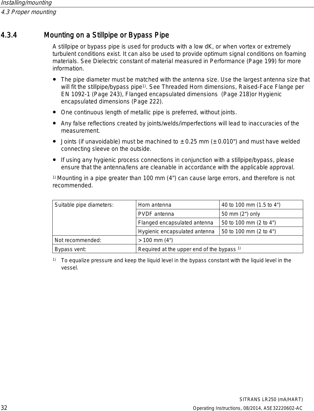
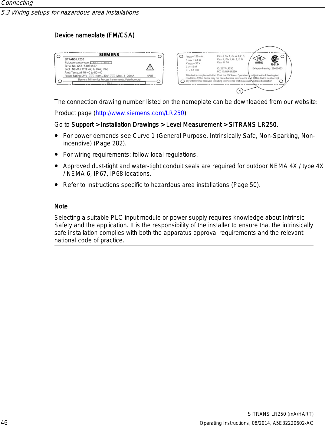
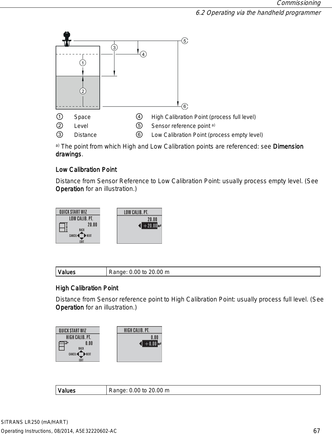
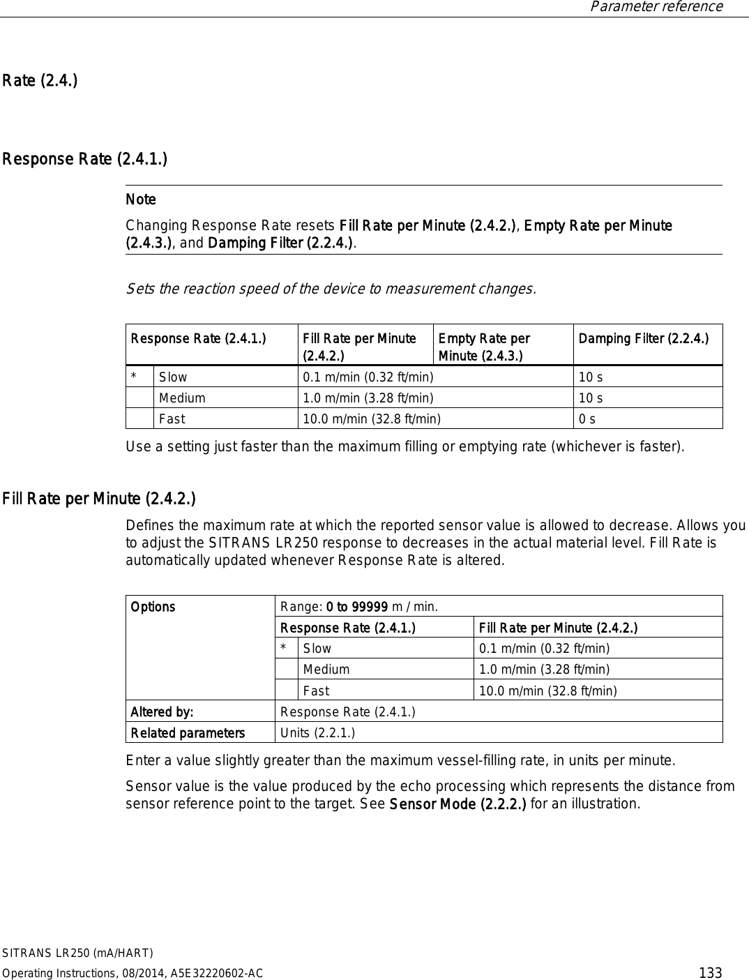
![Commissioning 6.2 Operating via the handheld programmer SITRANS LR250 (mA/HART) Operating Instructions, 08/2014, A5E32220602-AC 65 Material Selects the appropriate echo processing algorithms for the material [see Position Detect (2.8.4.2.) for more detail]. Options * LIQUID LIQUID LOW DK a) (low dielectric liquid – CLEF algorithm enabled) a) dK < 3.0 Response Rate Sets the reaction speed of the device to measurement changes in the target range. Use a setting just faster than the maximum filling or emptying rate (whichever is greater). Options Response Rate (1.3.) Fill rate per Minute (2.4.2.)/Empty rate per Minute (2.4.3.) * SLOW 0.1 m/min (0.32 ft/min) MED 1.0 m/min (3.28 ft/min) FAST 10.0 m/min (32.8 ft/min)](https://usermanual.wiki/Siemens-Canada-Siemens-Milltronics-Process-Instruments/LR250.User-Manual-1/User-Guide-2277916-Page-67.png)
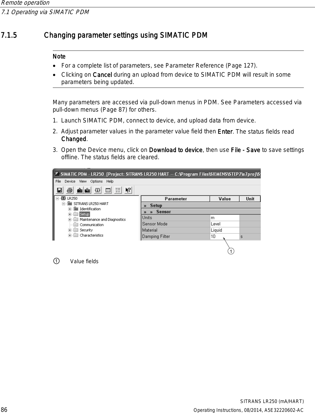
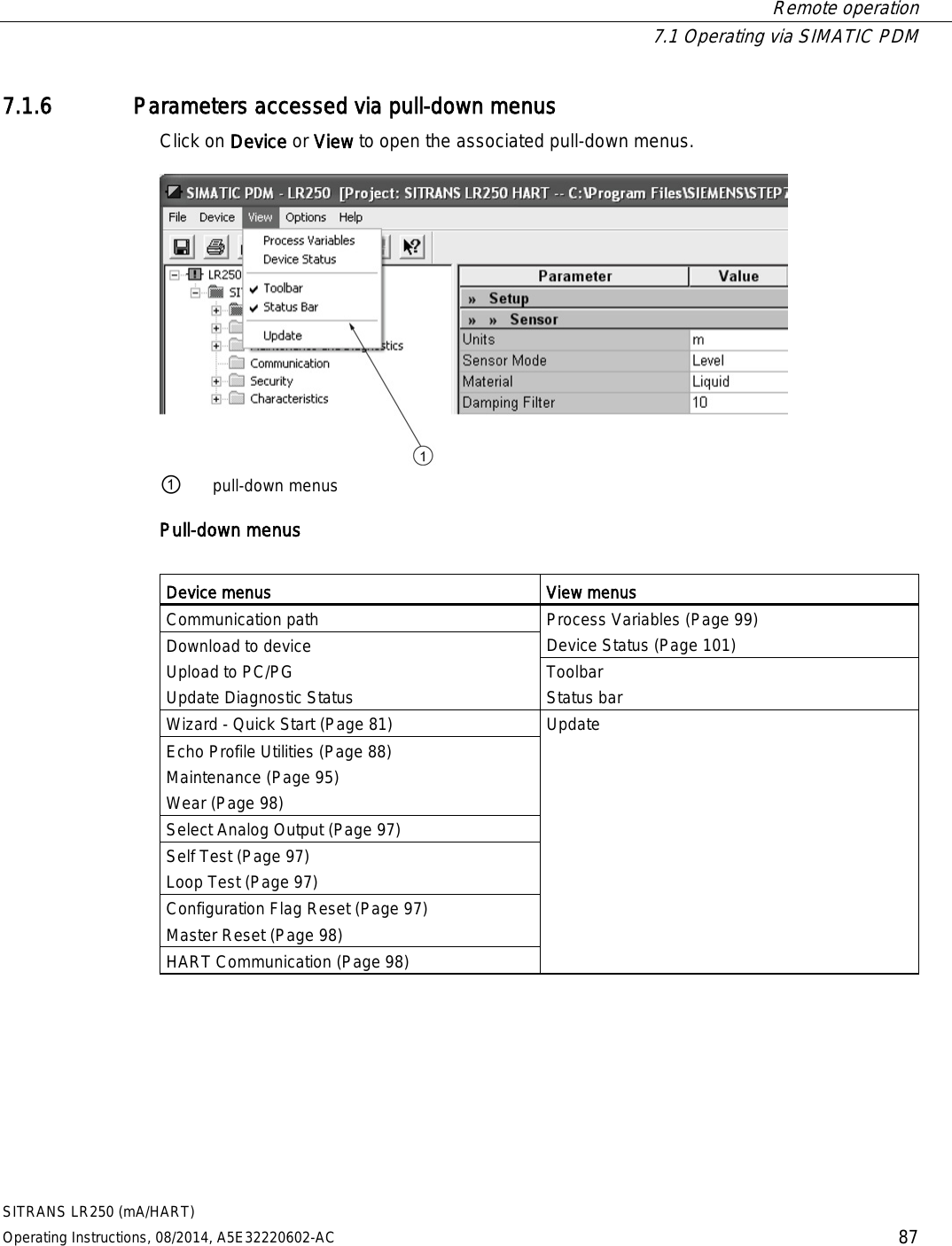
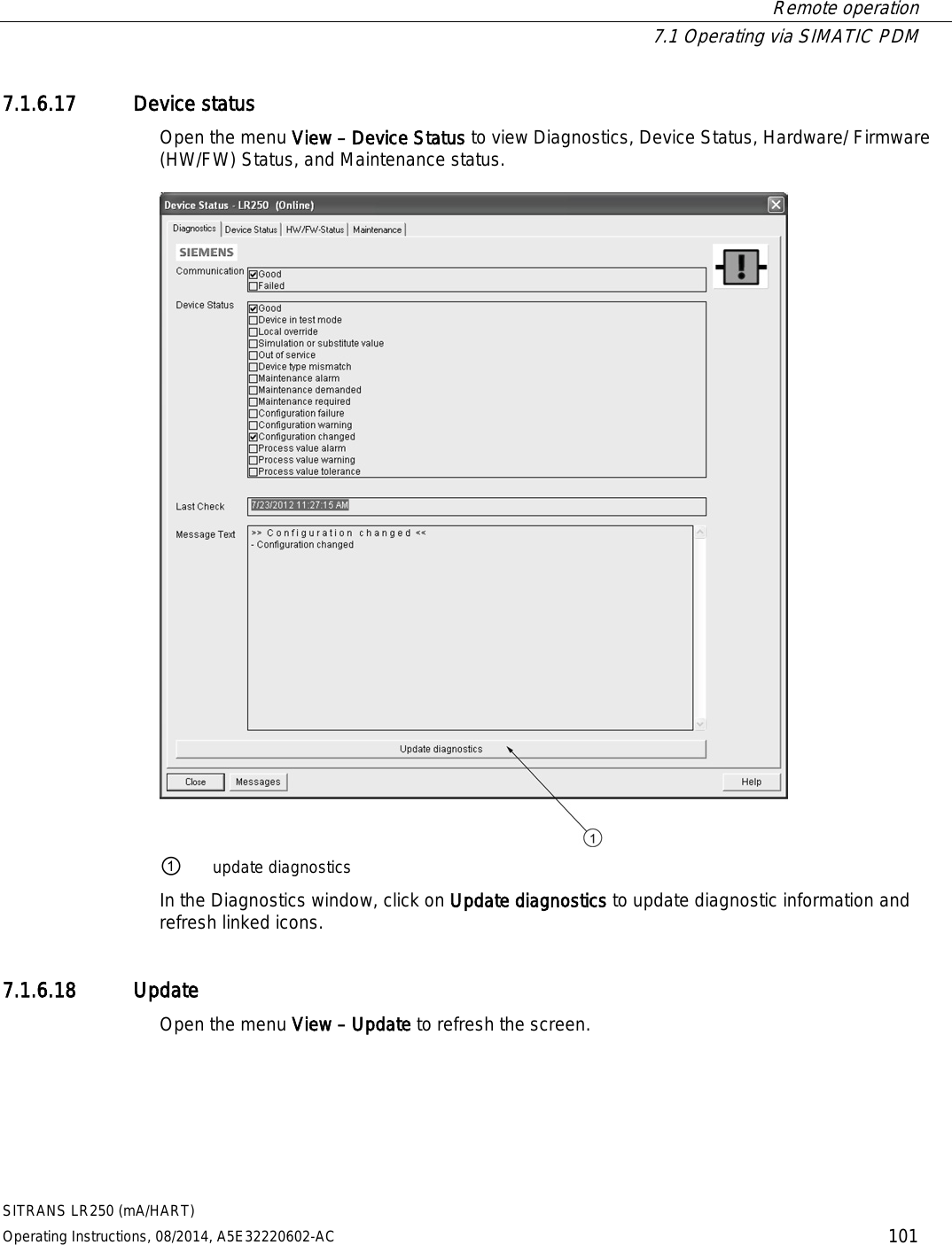
![Remote operation 7.1 Operating via SIMATIC PDM SITRANS LR250 (mA/HART) 80 Operating Instructions, 08/2014, A5E32220602-AC 7.1.3 Updating the Electronic Device Description (EDD) You can locate the EDD in Device Catalog, under Sensors/Level/Echo/SiemensMilltronics/SITRANS LR250. The EDD revision must match the Firmware revision in the device. To install a new EDD: 1. Download the most current EDD from our website: Product page (http://www.siemens.com/LR250) 2. Save files to your computer, and extract the zipped file to an easily accessed location. 3. Launch SIMATIC PDM – Manage Device Catalog, browse to the unzipped EDD file and select it. 7.1.3.1 Configuring a new device Note • Clicking on Cancel during an upload from device to SIMATIC PDM will result in some parameters being updated. • Application Guides for setting up HART devices with SIMATIC PDM can be downloaded from our website: Product page (http://www.siemens.com/LR250). 1. Check that you have the most recent EDD, and if necessary update it. [See Updating the Electronic Device Description (EDD) (Page 80) above]. 2. Launch SIMATIC Manager and create a new project for the device. 3. Open the menu Device – Master Reset and click on OK to perform a reset to Factory Defaults. 4. After the reset is complete upload parameters to the PC/PG. 5. Configure the device via the Quick Start wizard.](https://usermanual.wiki/Siemens-Canada-Siemens-Milltronics-Process-Instruments/LR250.User-Manual-1/User-Guide-2277916-Page-82.png)
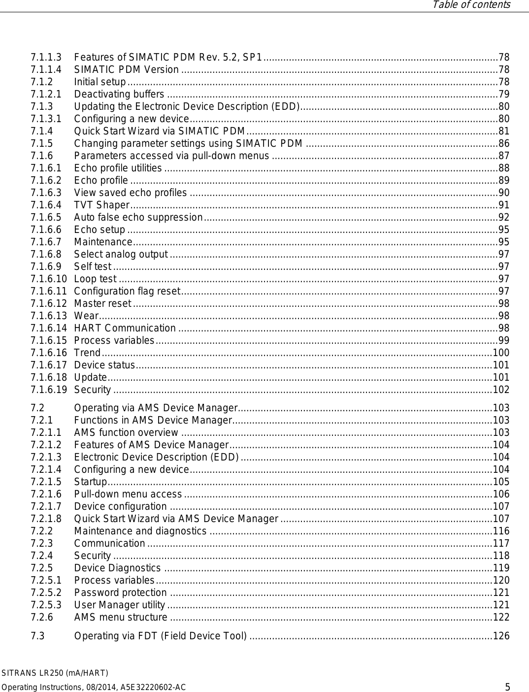
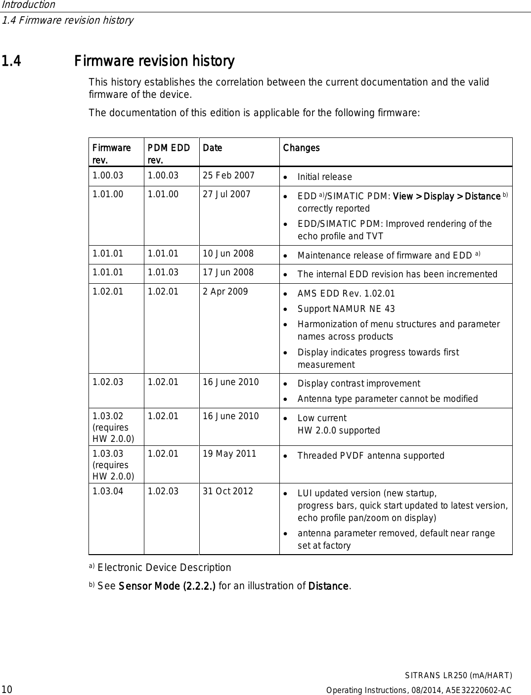
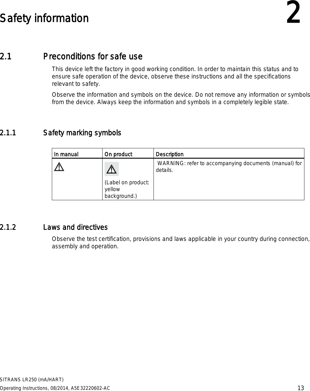
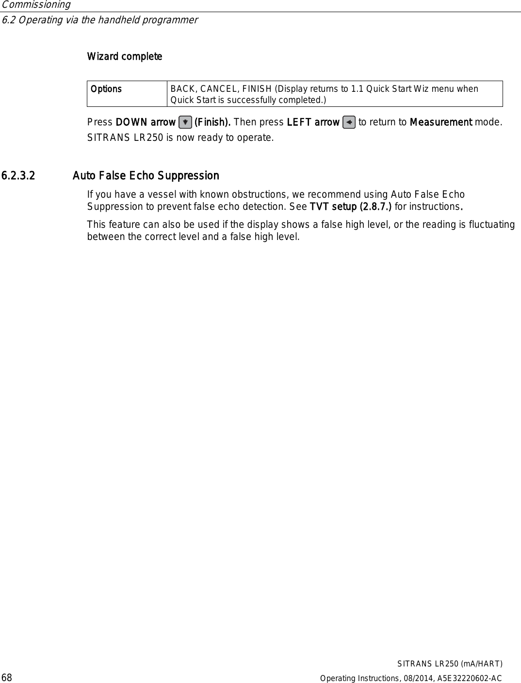
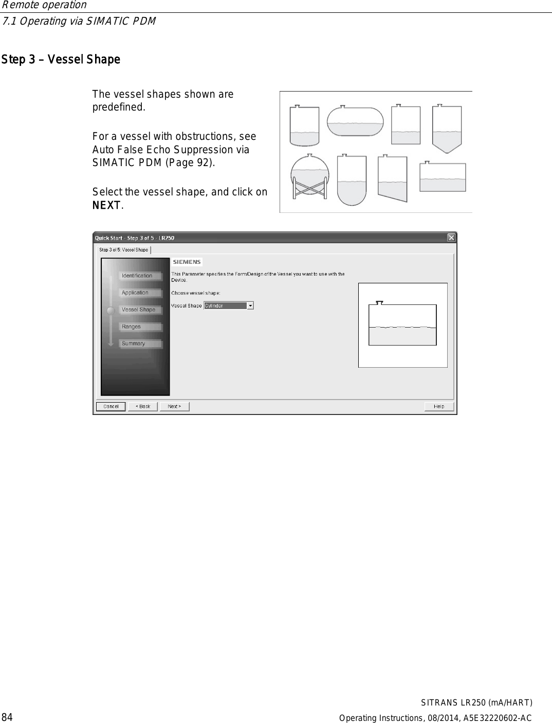
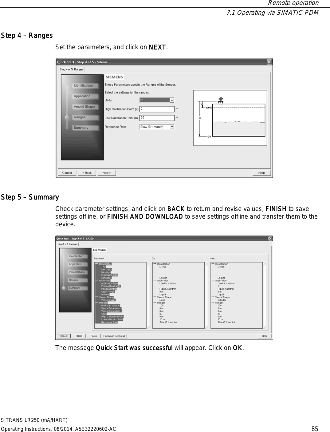
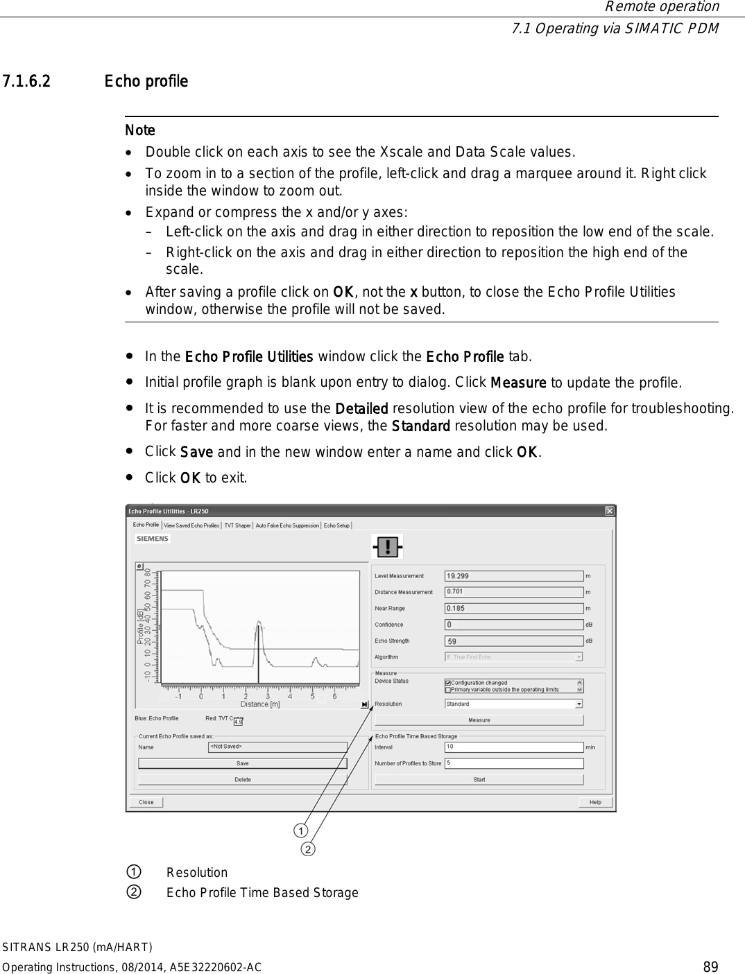
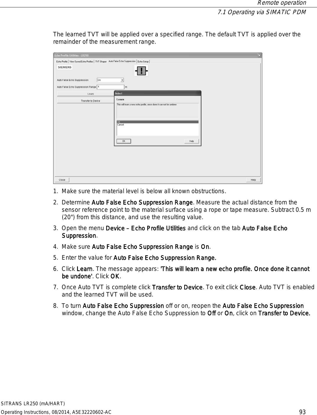
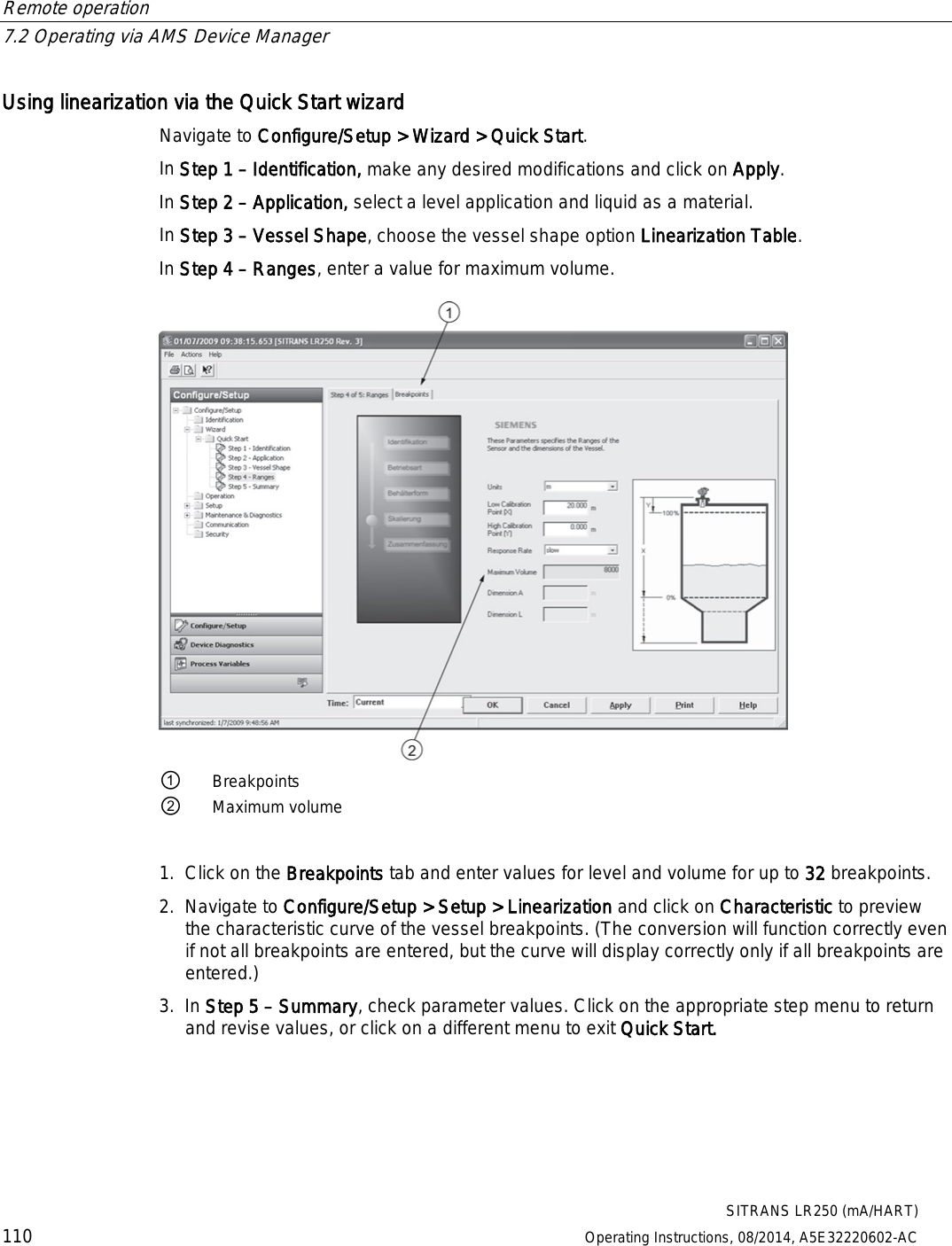
![Remote operation 7.1 Operating via SIMATIC PDM SITRANS LR250 (mA/HART) Operating Instructions, 08/2014, A5E32220602-AC 81 7.1.4 Quick Start Wizard via SIMATIC PDM The graphic Quick Start Wizard provides an easy step-by-step procedure that configures the device for a simple application. Please consult the operating instructions or online help for details on using SIMATIC PDM. 1. If you have not already done so, check that you have the most up-to-date Electronic Device Description (EDD) for your device. [See Configuring a new device (Page 80).] 2. Launch SIMATIC Manager and create a new project. Application Guides for setting up HART and PROFIBUS PA devices with SIMATIC PDM can be downloaded from the product page of our website: Product page (http://www.siemens.com/LR250) Quick start Note • A reset to Factory Defaults should be performed before running the Quick Start Wizard if device has been used in a previous application. See Master Reset via SIMATIC PDM (Page 98). • The Quick Start wizard settings are inter-related and changes apply only after you click on FINISH AND DOWNLOAD at the end of the last step to save settings offline and transfer them to the device. • Do not use the Quick Start Wizard to modify individual parameters: for quick access to echo profile parameters, see Echo Profile via SIMATIC PDM (Page 89) or see Parameter Reference (Page 127) for a complete list. (Perform customization only after the Quick Start has been completed.) • Click on BACK to return and revise settings or CANCEL to exit the Quick Start. • For a vessel with obstructions see Auto False Echo Suppression via SIMATIC PDM (Page 92). Launch SIMATIC PDM, open the menu Device – Wizard - Quick Start, and follow steps 1 to 5. ① Quick Start](https://usermanual.wiki/Siemens-Canada-Siemens-Milltronics-Process-Instruments/LR250.User-Manual-1/User-Guide-2277916-Page-83.png)
![Remote operation 7.1 Operating via SIMATIC PDM SITRANS LR250 (mA/HART) Operating Instructions, 08/2014, A5E32220602-AC 97 7.1.6.8 Select analog output Allows you to set the mA Output to report Level, Distance, Space, or Volume. See Current Output Function (2.6.1.) for an illustration. If a volume application is selected, mA Output is automatically set to Volume. See Analog Output (Page 262) for more details. 1. Open the menu Device – Select Analog Output. 2. Select Analog Output window displays the current setting: click OK. 3. Select a different setting and click OK. 4. Select Analog Output window displays the new setting: click OK. 7.1.6.9 Self test Checks memory (RAM and Flash). If there are no errors, returns the message 'Self Test OK.' If errors are found, returns the message 'Self Test Fails'. Open the menu Device – Self Test, select Yes and click OK. 7.1.6.10 Loop test Note The simulated AO (Analog Output) value influences output to the control system. Allows you to input a simulated value (4 mA, 20 mA, or a user-defined value) in order to test the functioning of the mA connections during commissioning or maintenance of the device. The range is 3.56 mA to 22.6 mA, see mA Output Value (2.6.6.). To simulate a user-defined mA value: 1. Open the menu Device – Loop Test. 2. Select Other, enter the new value, and click on OK. The message ’Field Device fixed at [new value]’ appears. Click on OK. The Loop Test window remains open. 3. When you are ready to end simulation, select End and click on OK to return the device to the actual output value. 7.1.6.11 Configuration flag reset To reset the configuration flag to zero, open the menu Device – Configuration Flag Reset and perform a reset.](https://usermanual.wiki/Siemens-Canada-Siemens-Milltronics-Process-Instruments/LR250.User-Manual-1/User-Guide-2277916-Page-99.png)
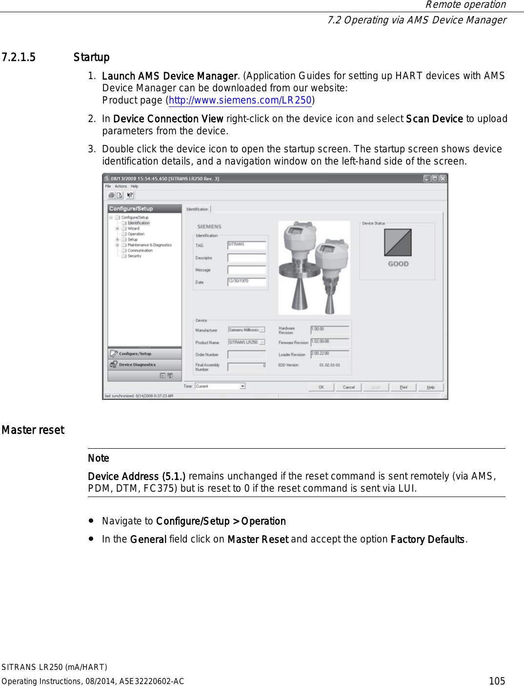
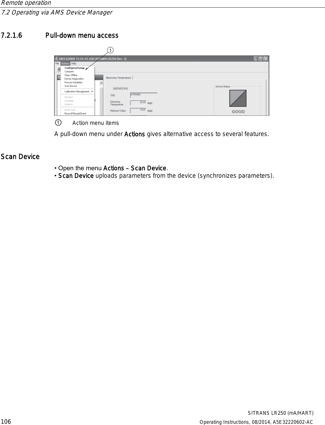
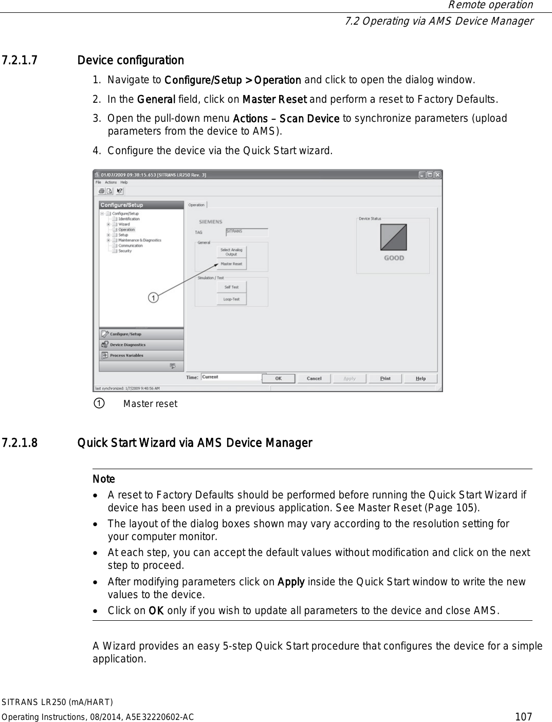
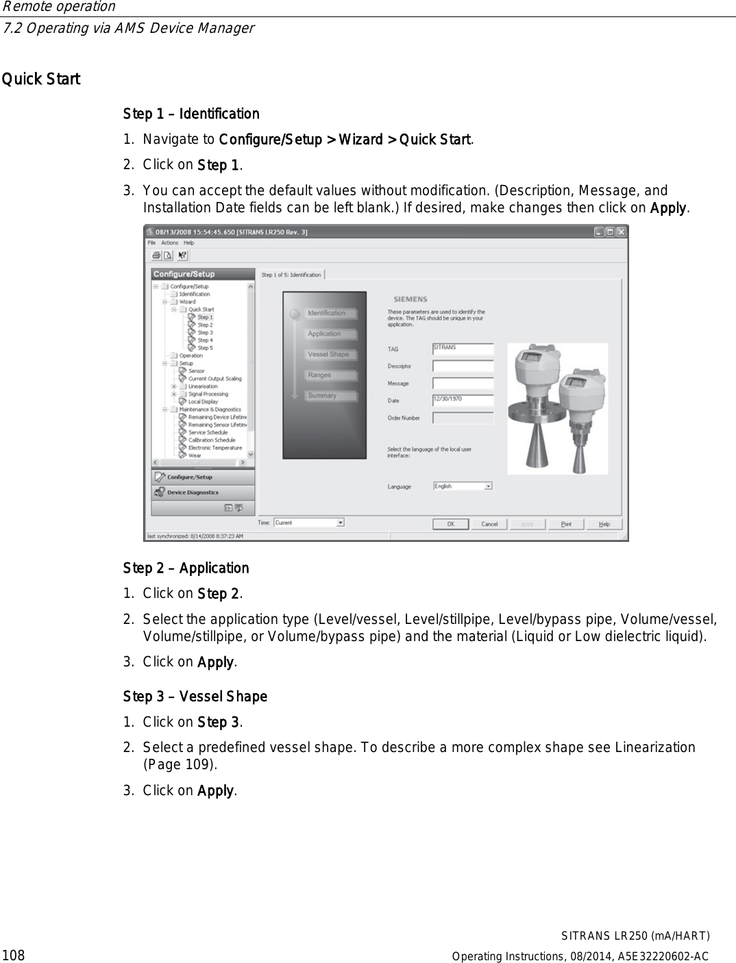
![Remote operation 7.2 Operating via AMS Device Manager SITRANS LR250 (mA/HART) Operating Instructions, 08/2014, A5E32220602-AC 111 Changing parameter settings using AMS Device Manager Note For a complete list of parameters, see Parameter Reference (Page 127). For more detailed explanations of the parameters listed below see the pages referenced. 1. Adjust parameter values in the parameter value field in Configure/Setup view, then click on Apply to write the new values to the device. The parameter field will display in yellow until the value has been written to the device. 2. Click on OK only if you wish to update all parameters and exit AMS. Operation Navigate to Configure/Setup > Operation and click on Operation to open the dialog window for access to: General ● Select Analog Output [see Select Analog Output (Page 97)] ● Master Reset [see Master Reset (Page 98)] Simulation/Test ● Self Test [see Self Test (Page 97)] ● Loop Test [see Loop Test (Page 97)]](https://usermanual.wiki/Siemens-Canada-Siemens-Milltronics-Process-Instruments/LR250.User-Manual-1/User-Guide-2277916-Page-113.png)
![Remote operation 7.2 Operating via AMS Device Manager SITRANS LR250 (mA/HART) 112 Operating Instructions, 08/2014, A5E32220602-AC Setup Note For more detailed explanations of the parameters listed below see the pages referenced. Sensor Navigate to Configure/Setup > Setup and click on Sensor for access to: General [see Sensor (2.2.)] ● Units ● Operating Mode ● Material ● Damping Filter Calibration [see Calibration (2.3.)] ● Low Calibration Point ● High Calibration Point ● Sensor Offset](https://usermanual.wiki/Siemens-Canada-Siemens-Milltronics-Process-Instruments/LR250.User-Manual-1/User-Guide-2277916-Page-114.png)
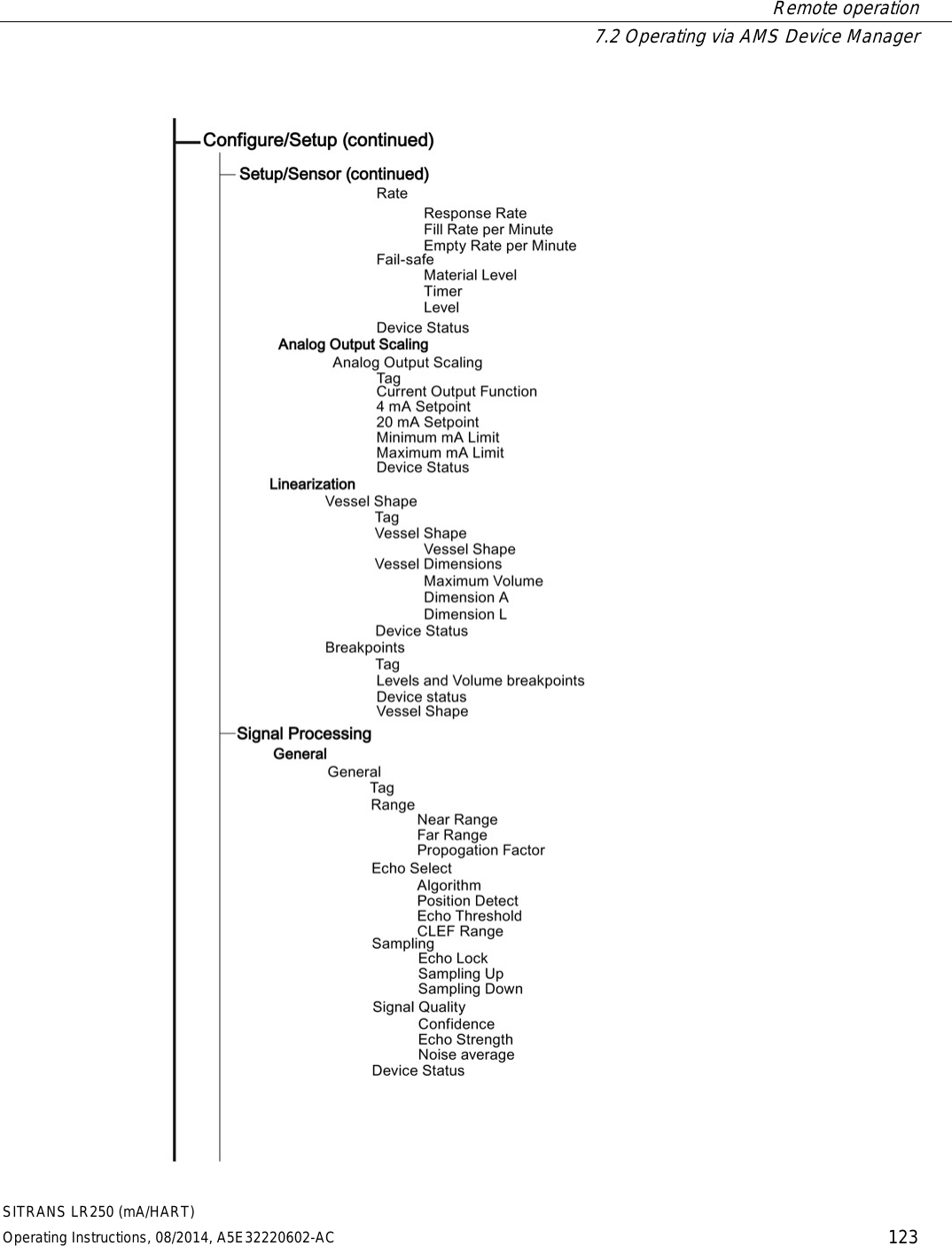
![Remote operation 7.2 Operating via AMS Device Manager SITRANS LR250 (mA/HART) Operating Instructions, 08/2014, A5E32220602-AC 113 Rate [see Rate (2.4.)] ● Response Rate ● Fill Rate per Minute ● Empty Rate per Minute Fail-safe [see Fail-safe (2.5.)] ● Material level ● Timer ● Level Analog Output Scale Navigate to Configure/Setup > Setup and click on Analog Output Scaling for access to: Analog Output Scaling [see Analog Output Scaling (2.6.)] ● Current Output Function ● 4 mA Setpoint ● 20 mA Setpoint ● Minimum mA Limit ● Maximum mA Limit](https://usermanual.wiki/Siemens-Canada-Siemens-Milltronics-Process-Instruments/LR250.User-Manual-1/User-Guide-2277916-Page-115.png)
![Remote operation 7.2 Operating via AMS Device Manager SITRANS LR250 (mA/HART) 114 Operating Instructions, 08/2014, A5E32220602-AC Signal Processing General Navigate to Configure/Setup > Setup > Signal Processing and click on General for access to: Range [see Signal Processing (2.8.)] ● Near Range ● Far Range ● Propagation Factor Echo Select [see Echo Select (2.8.4.)] ● Algorithm ● Position Detect ● Echo Threshold ● CLEF Range Sampling [see Sampling (2.8.5.)] ● Echo Lock ● Sampling Up ● Sampling Down Signal Quality ● Confidence ● Echo Strength ● Noise Average](https://usermanual.wiki/Siemens-Canada-Siemens-Milltronics-Process-Instruments/LR250.User-Manual-1/User-Guide-2277916-Page-116.png)
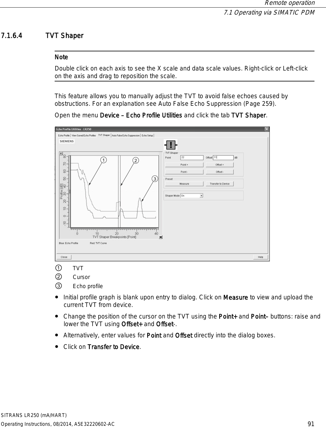
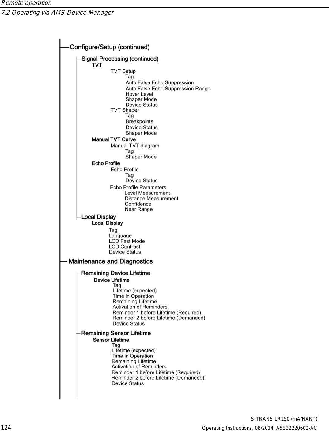
![Remote operation 7.2 Operating via AMS Device Manager SITRANS LR250 (mA/HART) Operating Instructions, 08/2014, A5E32220602-AC 115 TVT Modify the TVT to screen out false echoes. See Auto False Echo Suppression (2.8.7.1.) (Page 259). Navigate to Configure/Setup > Setup > Signal Processing and click on TVT. Click on one of the two tabs to access the parameters listed: TVT Setup [see TVT setup (2.8.7.)] ● Auto False Echo Suppression ● Auto False Echo Suppression Range ● Hover Level ● Shaper Mode TVT Shaper ● Shaper breakpoints 1 to 40. (Turn TVT Setup/Shaper Mode on to activate.) Manual TVT Curve Displays the effects of the TVT shaper modifications. Navigate to Configure/Setup > Setup > Signal Processing and click on Manual TVT Curve.](https://usermanual.wiki/Siemens-Canada-Siemens-Milltronics-Process-Instruments/LR250.User-Manual-1/User-Guide-2277916-Page-117.png)
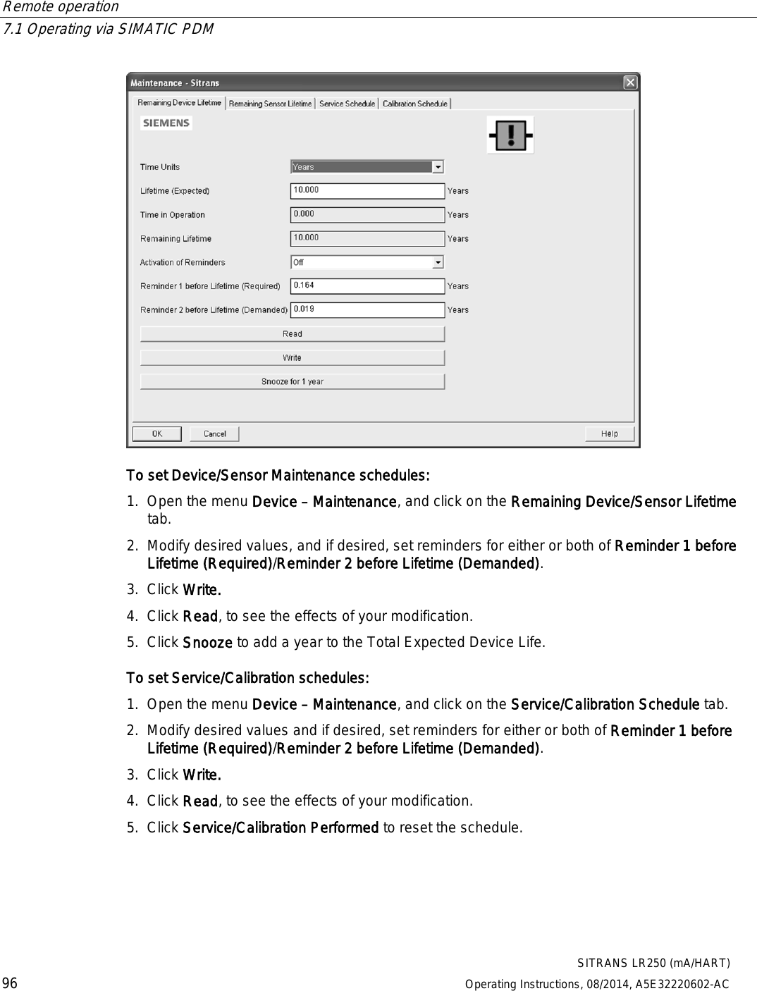
![Remote operation 7.2 Operating via AMS Device Manager SITRANS LR250 (mA/HART) 116 Operating Instructions, 08/2014, A5E32220602-AC Echo Profile ● Navigate to Configure/Setup > Setup > Signal Processing and click on Echo Profile. ● Select Standard operation for faster display. Local Display Navigate to Configure/Setup > Setup > Local Display for access to: ● Language ● LCD Fast Mode [see LCD Fast Mode (4.9.)] ● LCD Contrast [see LCD Contrast (4.10.)] 7.2.2 Maintenance and diagnostics Navigate to Maintenance and Diagnostics for access to: Remaining Device Lifetime [see Remaining Device Lifetime (4.2.)] ● Lifetime (expected) ● Time in Operation ● Remaining Lifetime ● Activation of Reminders ● Reminder 1 before Lifetime (Required) ● Reminder 2 before Lifetime (Demanded) Remaining Sensor Lifetime [see Remaining Sensor Lifetime (4.3.)] ● Lifetime (expected) ● Time in Operation ● Remaining Lifetime ● Activation of Reminders ● Reminder 1 before Lifetime (Required) ● Reminder 2 before Lifetime (Demanded)](https://usermanual.wiki/Siemens-Canada-Siemens-Milltronics-Process-Instruments/LR250.User-Manual-1/User-Guide-2277916-Page-118.png)
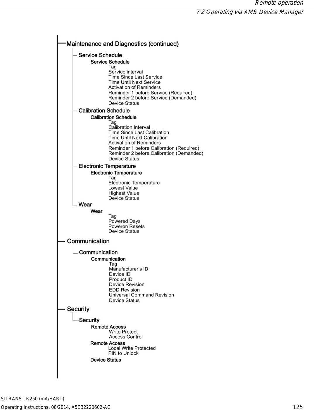
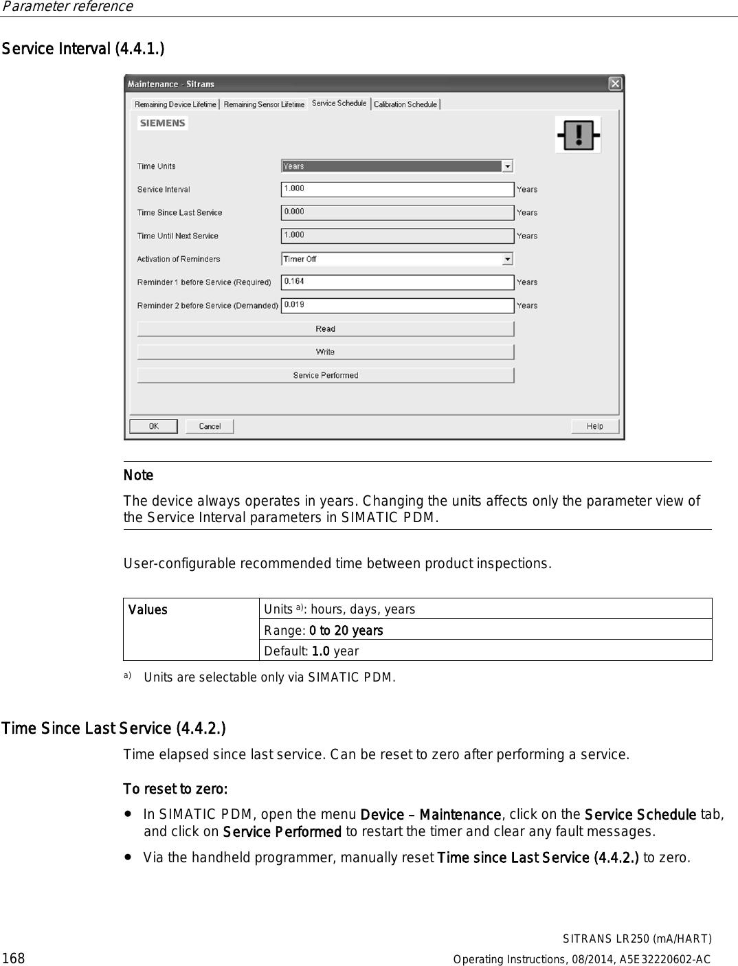
![Remote operation 7.2 Operating via AMS Device Manager SITRANS LR250 (mA/HART) Operating Instructions, 08/2014, A5E32220602-AC 117 Service Schedule [see Service Schedule (4.4.)] ● Service Interval ● Time Since Last Service ● Time Until Next Service ● Activation of Reminders ● Reminder 1 before Service (Required) ● Reminder 2 before Service (Demanded) Calibration Schedule [see Calibration Schedule (4.5.)] ● Calibration Interval ● Time Since Last Calibration ● Time Until Next Calibration ● Activation of Reminders ● Reminder 1 before Calibration (Required) ● Reminder 2 before Calibration (Demanded) Electronic Temperature ● Electronic Temperature ● Lowest Value ● Highest Value Wear ● Powered Days ● Poweron Resets See Wear via SIMATIC PDM (Page 98) for more detail. 7.2.3 Communication Navigate to Communication to read the following: Tag; Manufacturer’s ID; Device ID; Product ID; Device Revision; EDD Revision; Universal Command Revision](https://usermanual.wiki/Siemens-Canada-Siemens-Milltronics-Process-Instruments/LR250.User-Manual-1/User-Guide-2277916-Page-119.png)
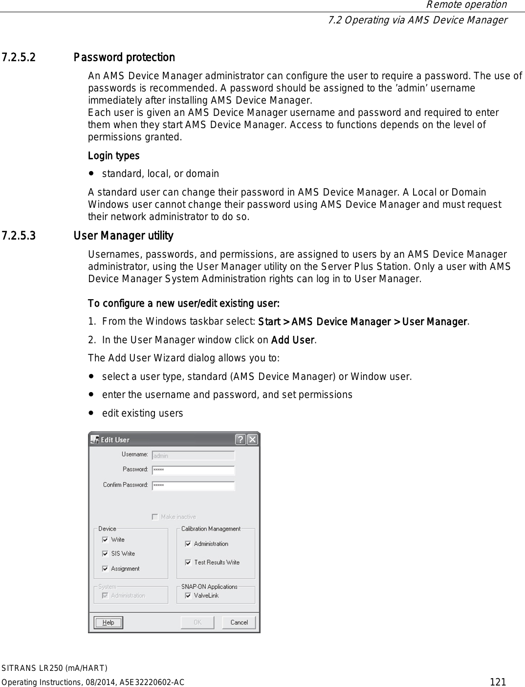
![Remote operation 7.2 Operating via AMS Device Manager SITRANS LR250 (mA/HART) 118 Operating Instructions, 08/2014, A5E32220602-AC 7.2.4 Security Navigate to Configure/Setup > Security to access: Remote Access [see Remote Access (6.1.)] Note If access control is changed to limit remote access, it can only be reset via the handheld programmer. See Access Control (6.1.1.). ● Write Protect (read only) ● Access Control Local Access [see Local Access (6.2.)] ● Local Write Protected ● PIN to Unlock See also Password Protection (Page 121).](https://usermanual.wiki/Siemens-Canada-Siemens-Milltronics-Process-Instruments/LR250.User-Manual-1/User-Guide-2277916-Page-120.png)

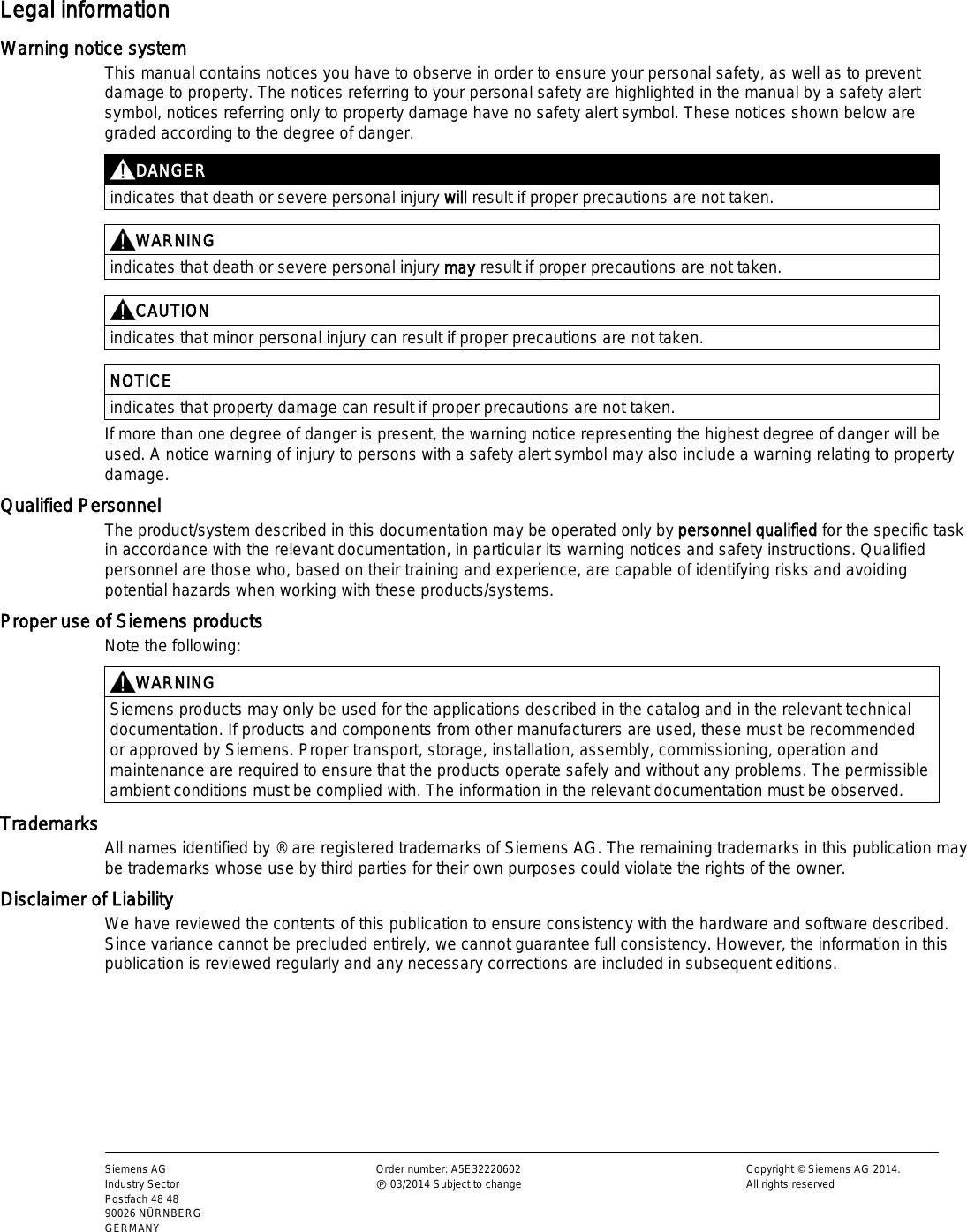
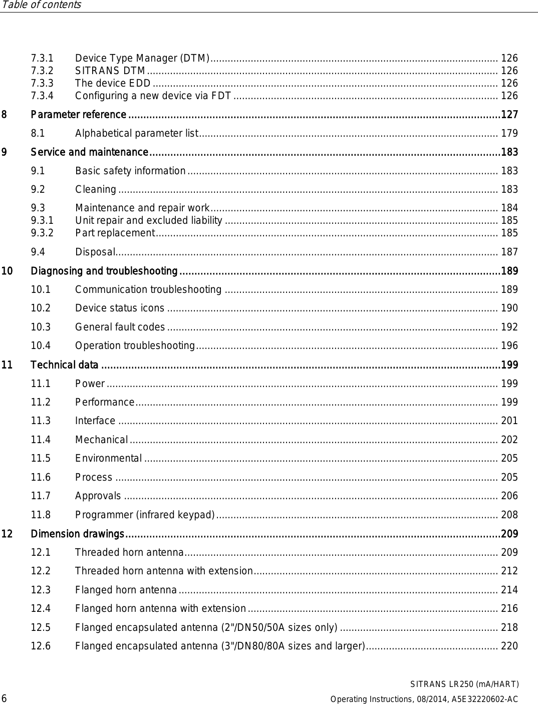
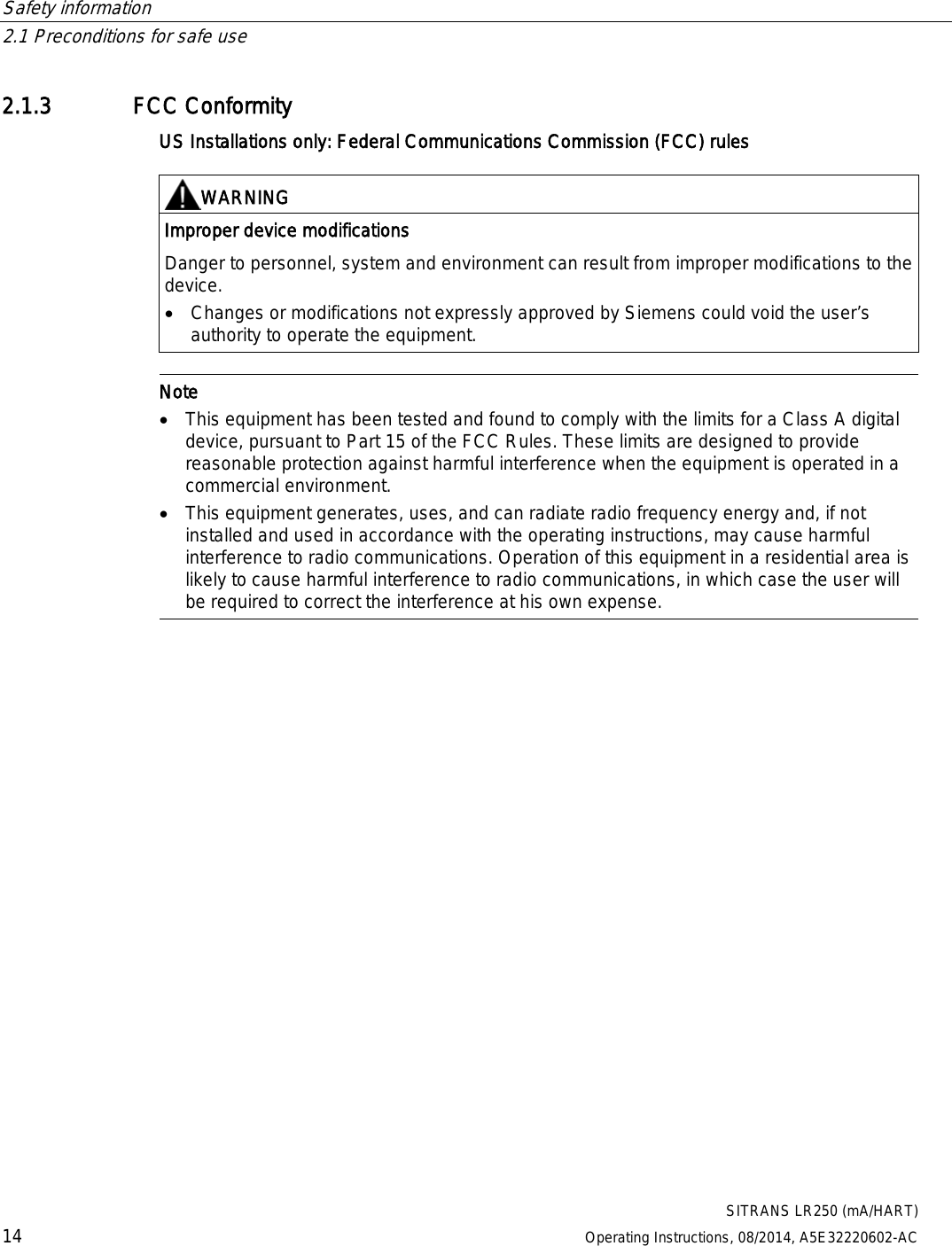
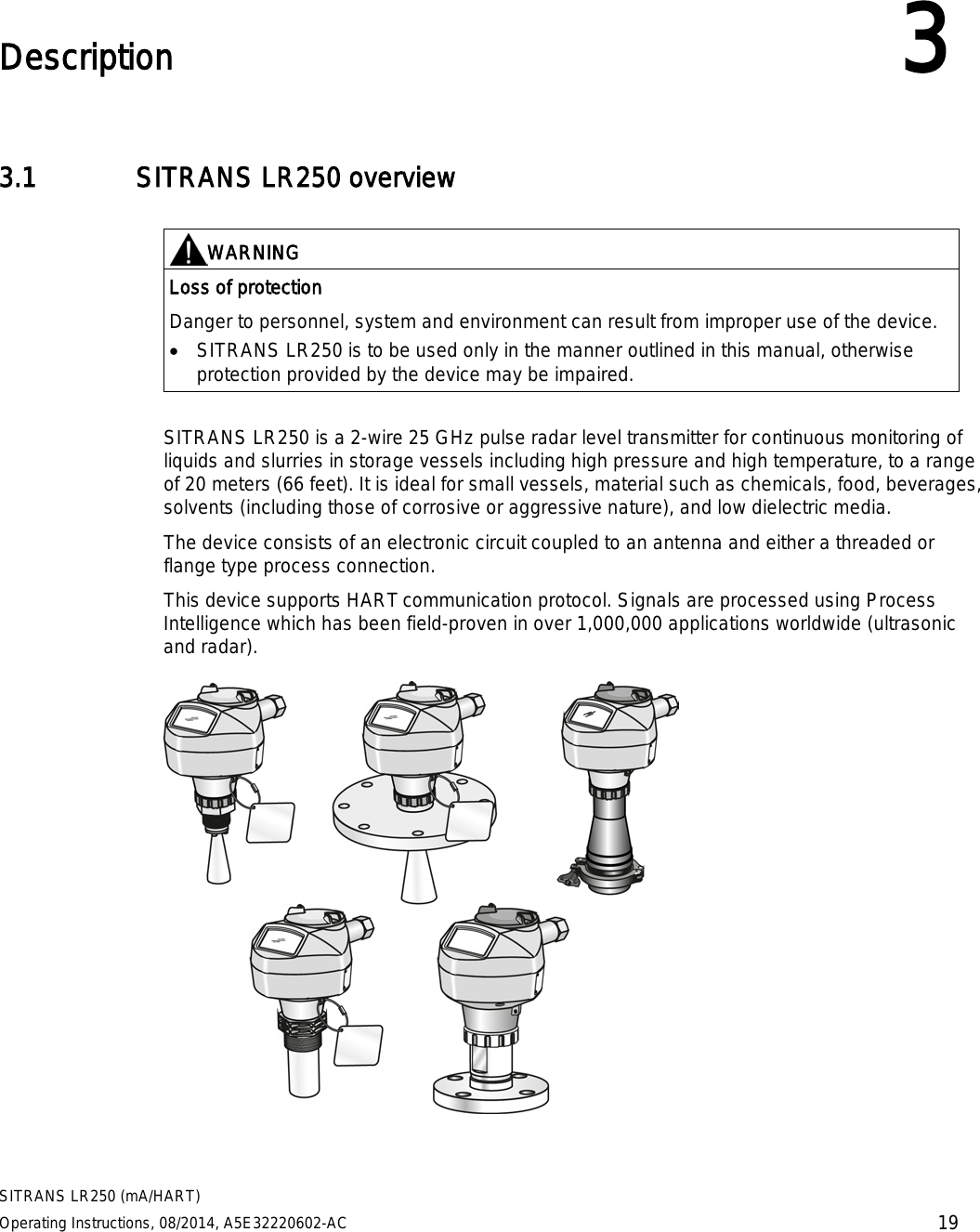
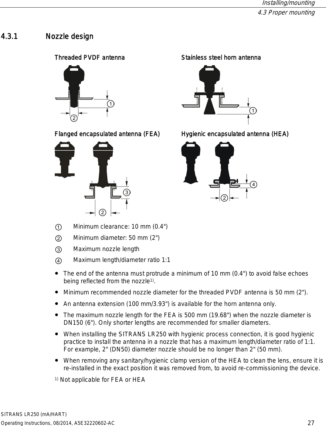
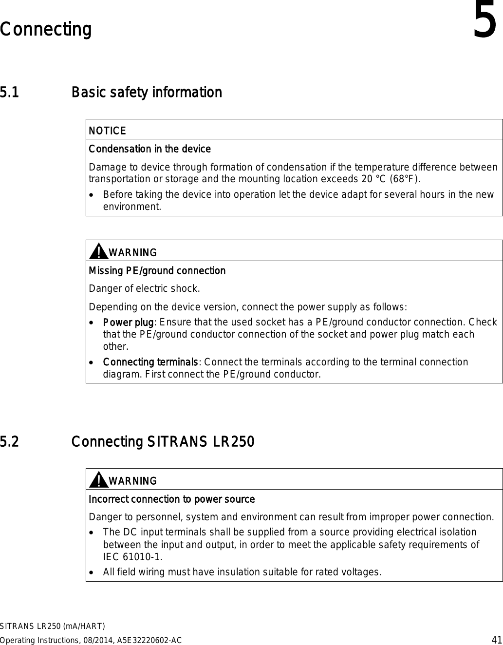
![Parameter reference SITRANS LR250 (mA/HART) 130 Operating Instructions, 08/2014, A5E32220602-AC Sensor Mode (2.2.2.) ① Sensor value ⑤ Sensor reference point [see Dimension drawings] (Page 209) ② Space ⑥ Low Calibration Point ③ Distance ⑦ Far range ④ High Calibration Point ⑧ Level Mode Description Reference point NO SERVICE Measurement and associated loop current are not updated, and the device defaults to Fail-safe mode a). n/a LEVEL * Distance to material surface Low Calibration Point (process empty level) SPACE Distance to material surface High Calibration Point (process full level) DISTANCE Distance to material surface Sensor reference point a) See Material Level (2.5.1.) for more detail.](https://usermanual.wiki/Siemens-Canada-Siemens-Milltronics-Process-Instruments/LR250.User-Manual-1/User-Guide-2277916-Page-132.png)
![Parameter reference SITRANS LR250 (mA/HART) Operating Instructions, 08/2014, A5E32220602-AC 131 Material (2.2.3.) Automatically configures the device to operate in the chosen application type, by changing one or more of the following parameters: Propagation Factor (2.8.3.), Position Detect (2.8.4.2.), and/or CLEF Range (2.8.4.4.). Options * LIQUID LIQUID LOW DK a) (low dielectric liquid - CLEF algorithm enabled) Related parameters Propagation Factor (2.8.3.) Position Detect (2.8.4.2.) CLEF Range (2.8.4.4.) a) dK < 3.0 You can configure each of the related parameters to suit your particular application. Damping Filter (2.2.4.) The time constant for the damping filter. The damping filter smooths out the response to a sudden change in level. This is an exponential filter and the engineering unit is always in seconds [see Damping (Page 262) for more detail]. Values Range: 0 to 100.000 s Default: 10.000 s Calibration (2.3.) Note We recommend using the Quick Start wizard to configure the device. Low Calibration Pt. (2.3.1.) Distance from sensor reference point1) to Low Calibration Point. Units are defined in Units (2.2.1.) Values Range: 0 to 20 m. Default: 20.00 m Related parameters Units (2.2.1.) Far Range (2.8.2.) 1) The point from which level measurement is referenced, see Threaded Horn Antenna with extension (Page 209), Flanged Horn with extension (Page 214), and Flanged encapsulated antenna (3"/DN80/80A sizes and larger) (Page 220).](https://usermanual.wiki/Siemens-Canada-Siemens-Milltronics-Process-Instruments/LR250.User-Manual-1/User-Guide-2277916-Page-133.png)
![Parameter reference SITRANS LR250 (mA/HART) 132 Operating Instructions, 08/2014, A5E32220602-AC High Calibration Pt. (2.3.2.) Distance from sensor reference point 1) to High Calibration Point. Units are defined in Units (2.2.1.). Values Range: 0 to 20 m. Default 0.00 m Related parameters Units (2.2.1.) Near Range (2.8.1.) When setting the High Calibration Point value, note that echoes are ignored within Near Range (2.8.1.). 1) The value produced by the echo processing which represents the distance from sensor reference point to the target. [see Threaded Horn Antenna with extension (Page 209), Flanged Horn with extension (Page 214), and Flanged encapsulated antenna (3"/DN80/80A sizes and larger) (Page 220)]. Sensor Offset (2.3.3.) A constant offset that can be added to or subtracted from the sensor value1) to compensate for a shifted sensor reference point. (For example, when adding a thicker gasket or reducing the standoff/nozzle height.) The units are defined in Units (2.2.1.). Values Range: -100 to 100 m. Default: 0.00 m Related parameters Units (2.2.1.) 1) The value produced by the echo processing which represents the distance from sensor reference point to the target, see Sensor Mode (2.2.2.).](https://usermanual.wiki/Siemens-Canada-Siemens-Milltronics-Process-Instruments/LR250.User-Manual-1/User-Guide-2277916-Page-134.png)
![Parameter reference SITRANS LR250 (mA/HART) Operating Instructions, 08/2014, A5E32220602-AC 135 Material Level (2.5.1.) Note The default setting depends whether your device is a standard or NAMUR NE 43-compliant device. Defines the mA output to use when the Fail-safe timer expires. STANDARD DEVICE Options HI 20.5 mA (max. mA Limit) LO 3.8 mA (min. mA Limit) * HOLD Last valid reading (default 22.6 mA) VALUE User-selected value [defined in Fail-Safe mA Value (2.5.3.)] NAMUR NE 43-COMPLIANT DEVICE1) Options HI 20.5 mA (max. mA Limit) LO 3.8 mA (min. mA Limit) HOLD Last valid reading * VALUE User-selected value [defined in Fail-Safe mA Value (2.5.3.): default 3.58 mA] 1) Orderable option LOE Timer (2.5.2.) Note When a Loss of Echo occurs Material Level (2.5.1.) determines the material level to be reported when the Fail-safe timer expires. See Loss of Echo (LOE) (Page 264) for more detail. Sets the time to elapse since the last valid reading, before the Fail-safe Level is reported. Values Range: 0.00 to 7200 seconds Default: 100 s](https://usermanual.wiki/Siemens-Canada-Siemens-Milltronics-Process-Instruments/LR250.User-Manual-1/User-Guide-2277916-Page-137.png)
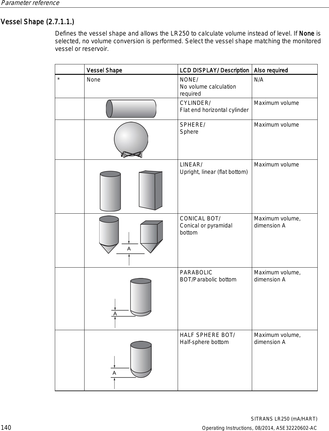
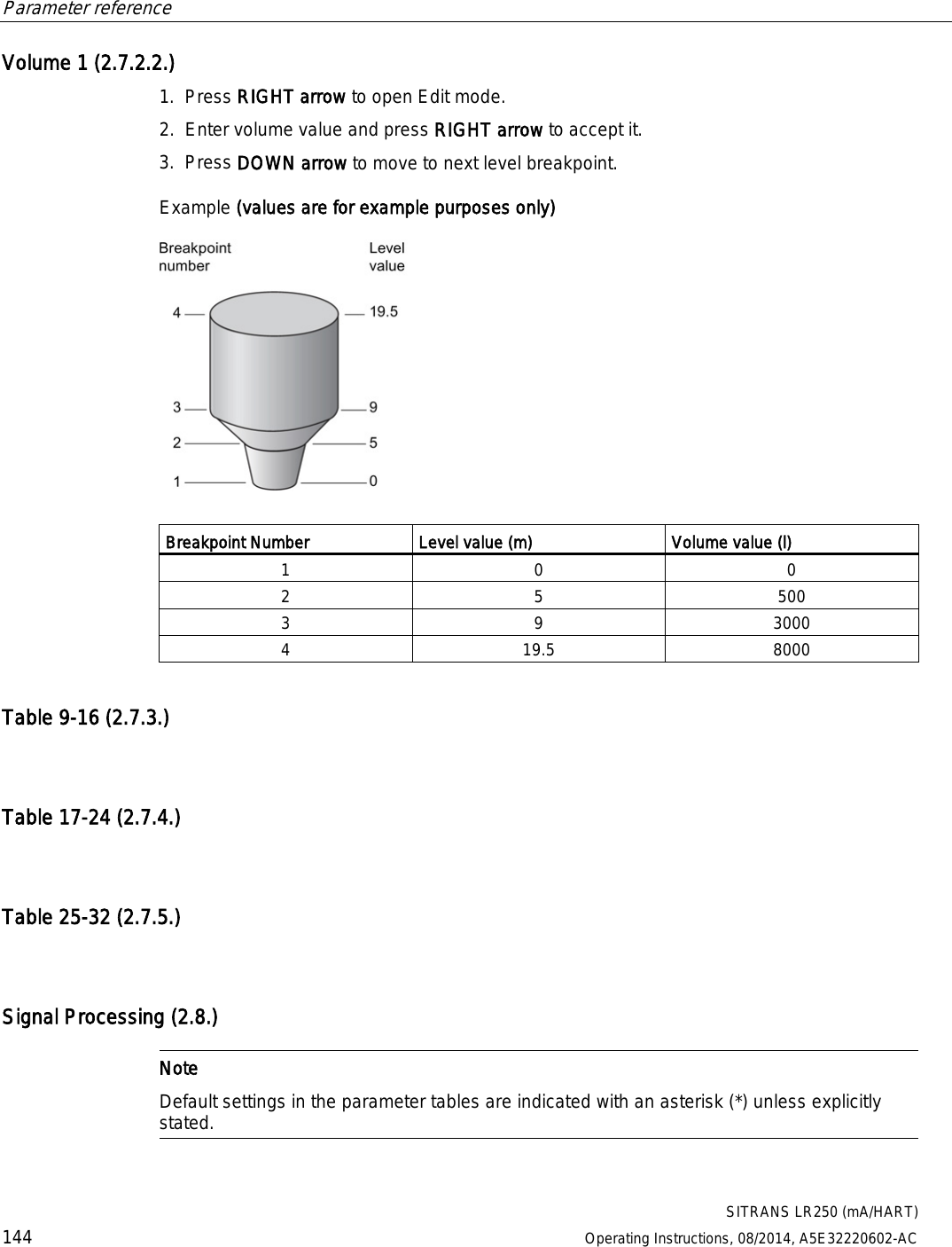
![Parameter reference SITRANS LR250 (mA/HART) Operating Instructions, 08/2014, A5E32220602-AC 141 Vessel Shape LCD DISPLAY/ Description Also required FLAT SLOPED BOT/ Flat sloped bottom Maximum volume, dimension A PARABOLIC ENDS/ Parabolic end horizontal cylinder Maximum volume, dimension A, dimension L LINEAR TABLE a) / Linearization table (level/volume breakpoints) Maximum volume, tables 1-32 level and volume breakpoints a) Linearization Table must be selected in order for level/volume values [see Table 1-8 (2.7.2.)] to be transferred. Maximum Volume (2.7.1.2.) The maximum volume of the vessel. Enter the vessel volume corresponding to High Calibration Point. For example, if your maximum vessel volume is 8000 L, enter a value of 8000. Volume units are defined by the user but are not explicitly stated or shown in the SITRANS LR250. Values Range: 0.0 to 99999 m Default: 100.0 Related Parameters Low Calibration Pt. (2.3.1.) High Calibration Pt. (2.3.2.) Vessel Shape (2.7.1.1.)](https://usermanual.wiki/Siemens-Canada-Siemens-Milltronics-Process-Instruments/LR250.User-Manual-1/User-Guide-2277916-Page-143.png)
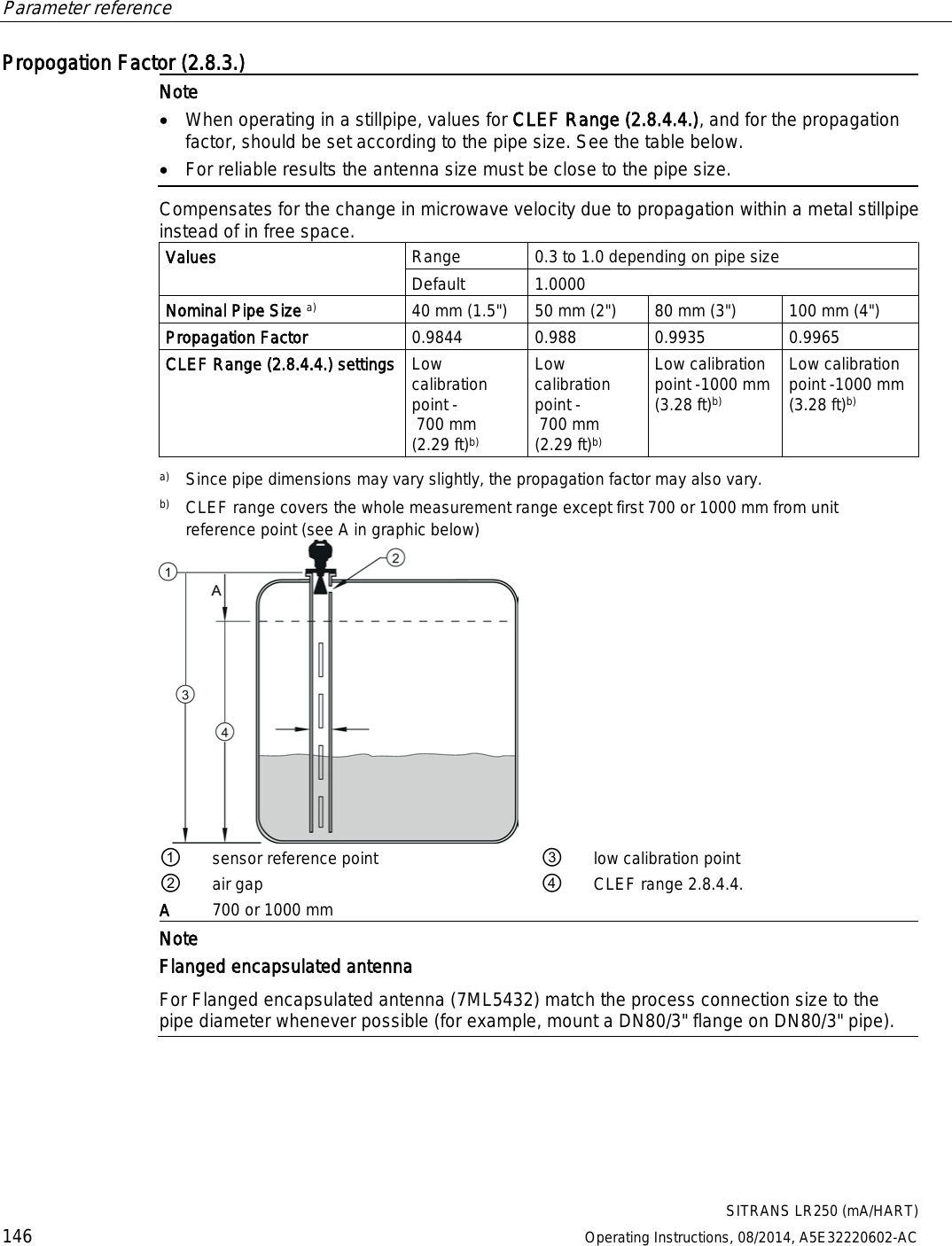
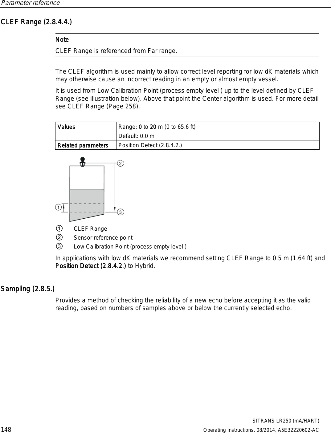
![Parameter reference SITRANS LR250 (mA/HART) Operating Instructions, 08/2014, A5E32220602-AC 145 Near Range (2.8.1.) The range in front of the device (measured from the sensor reference point) within which any echoes will be ignored. This is sometimes referred to as blanking or a dead zone. The factory setting is 50 mm (2") past the end of the antenna, and the default is dependent on the antenna type and process connection. [See Dimension drawings (Page 209) for antenna heights.] Values Range: 0 to 20 m (0 to 65.6 ft) Default depends on antenna type and process connection: Related parameters Units (2.2.1.) Far Range (2.8.2.) Note Far Range can extend beyond the bottom of the vessel. Allows the material level to drop below Low Calibration Point without generating a Loss of Echo (LOE) state. See Sensor Mode (2.2.2.) for an illustration. Values Range: Min. = Low Calibration Pt. Max. = 23 m (75.45 ft) Default: Value for Low Calibration Pt. + 1 m (3.28 ft) Related parameters Units (2.2.1.) Use this feature if the measured surface can drop below the Low Cal. Point in normal operation.](https://usermanual.wiki/Siemens-Canada-Siemens-Milltronics-Process-Instruments/LR250.User-Manual-1/User-Guide-2277916-Page-147.png)
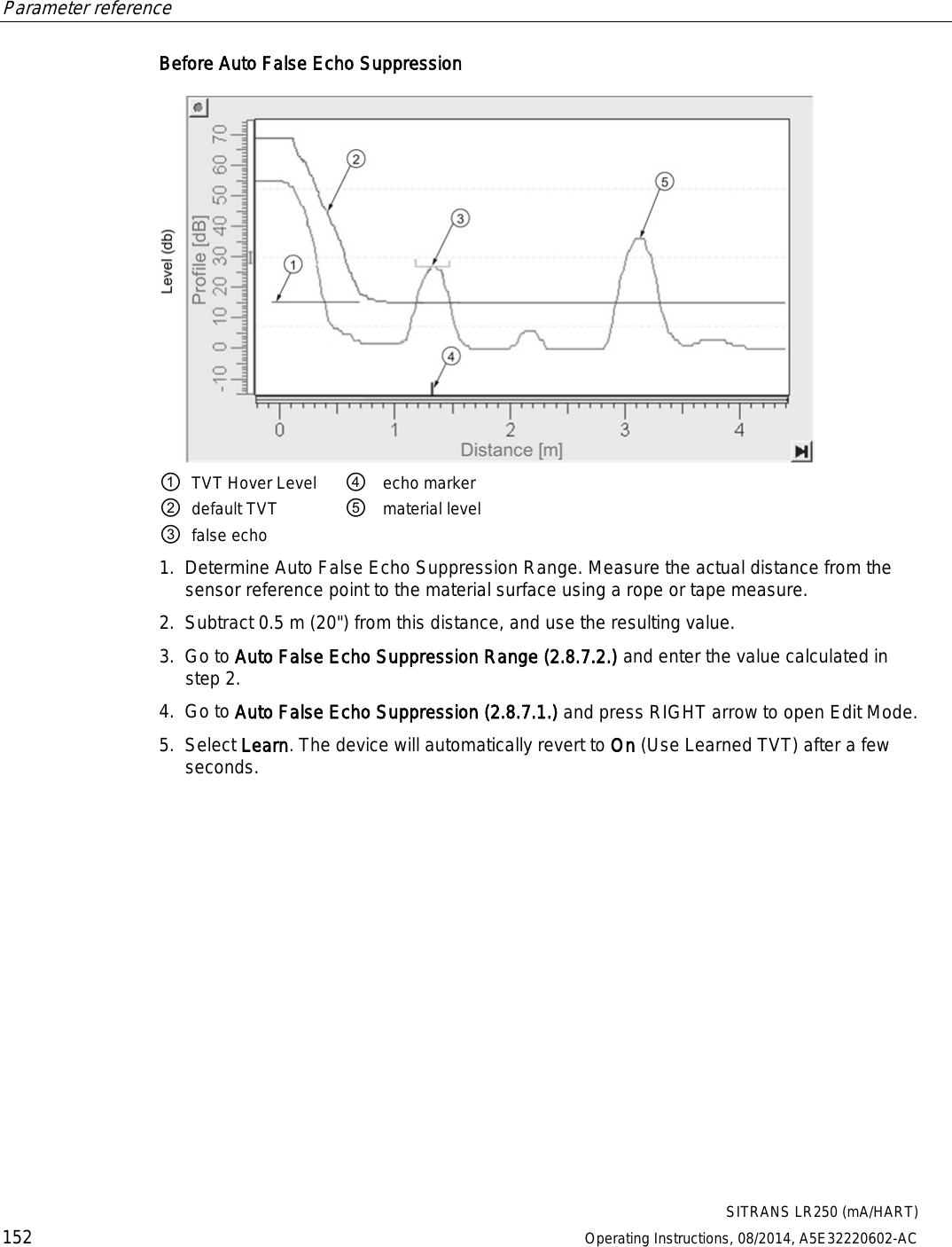
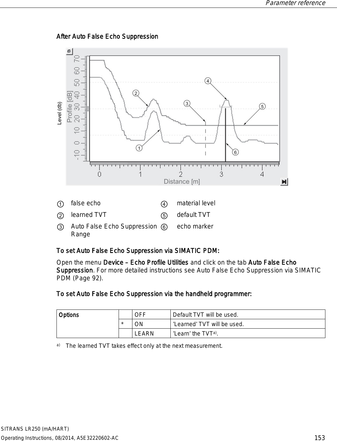
![Parameter reference SITRANS LR250 (mA/HART) 154 Operating Instructions, 08/2014, A5E32220602-AC Auto False Echo Suppression Range (2.8.7.2.) Note Changes take effect only at the next measurement. "Master reset" does not clear the learned/stored TVT, select "Off" to turn it off or "learn" for a new TVT. See Master Reset (4.1.) Specifies the range within which Learned TVT is used [see Auto False Echo Suppression (2.8.7.1.) for more detail]. Values Range: 0.00 to 20.00 m Default: 1.00 m Related parameters Units (2.2.1.) 1. Calculate range according to Auto False Echo Suppression (2.8.7.1.) steps 1 and 2. 2. Press RIGHT arrow to open Edit mode. 3. Enter the new value and press RIGHT arrow to accept it. 4. Set Auto False Echo Suppression (2.8.7.1.). Hover Level (2.8.7.3.) Note Changes take effect only at the next measurement. Defines how high the TVT (Time Varying Threshold) is placed above the noise floor of the echo profile, as a percentage of the difference between the peak of the largest echo in the profile and the noise floor. See Auto False Echo Suppression (2.8.7.1.) for an illustration. Values Range: 0 to 100% Default: 40% When the device is located in the center of the vessel, the TVT hover level may be lowered to increase the confidence level of the largest echo. Shaper Mode (2.8.7.4.) Enables/disables the TVT shaper. Options ON * OFF](https://usermanual.wiki/Siemens-Canada-Siemens-Milltronics-Process-Instruments/LR250.User-Manual-1/User-Guide-2277916-Page-156.png)
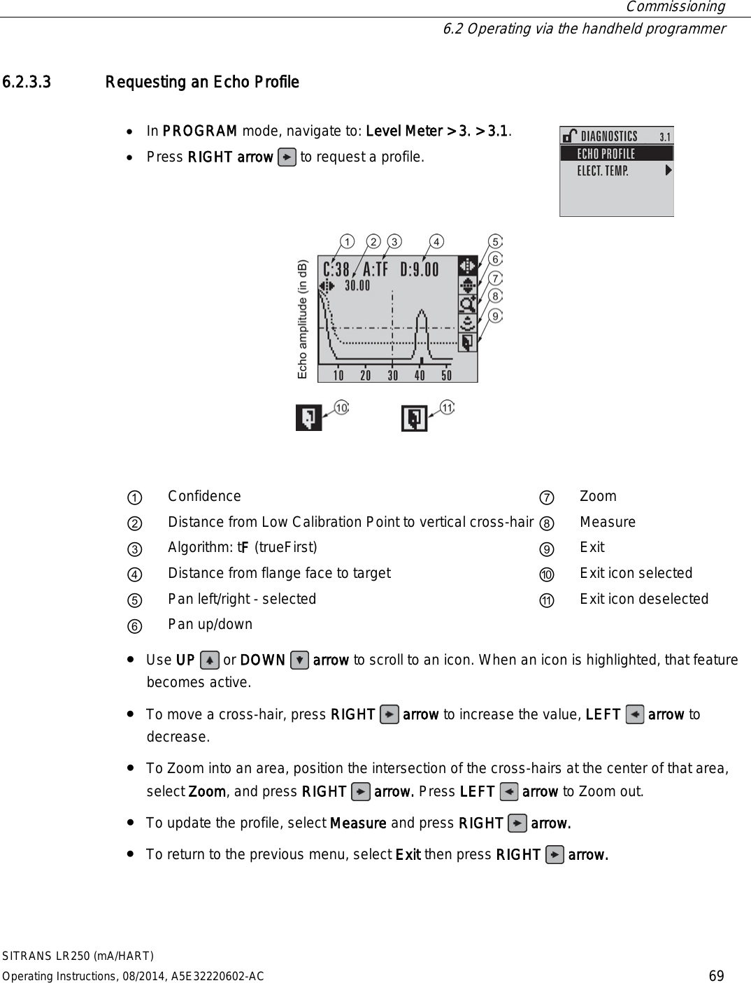
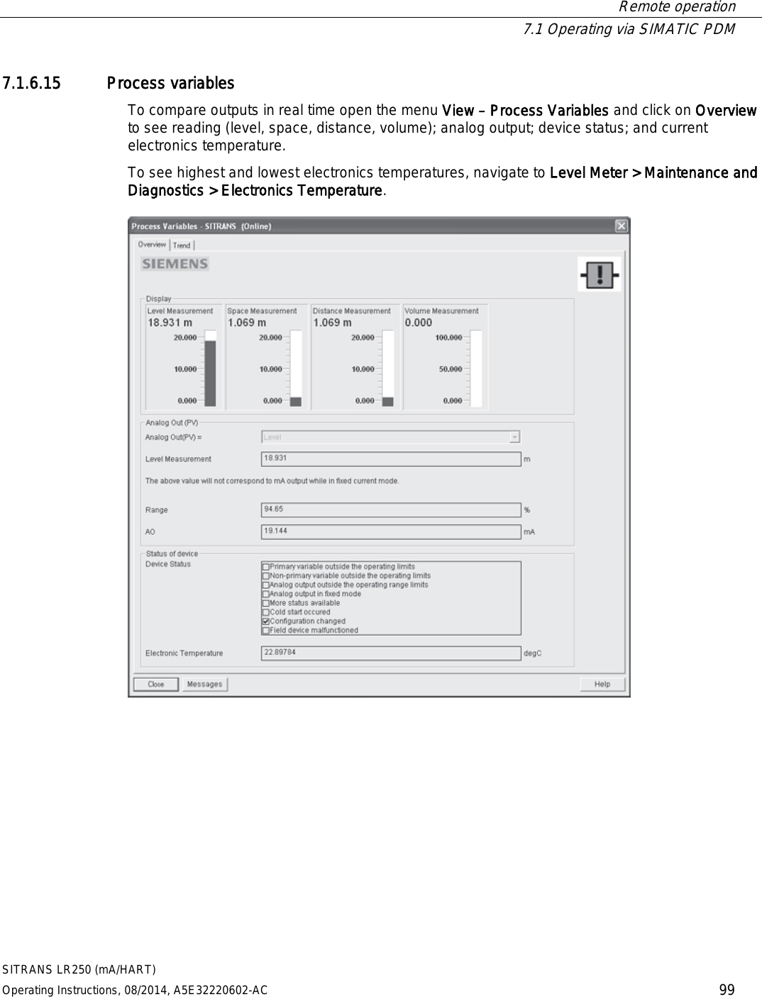
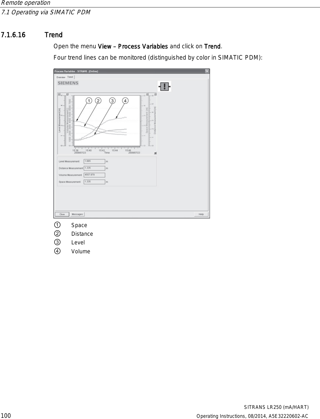
![Parameter reference SITRANS LR250 (mA/HART) 156 Operating Instructions, 08/2014, A5E32220602-AC Breakpoint 28-36 (2.8.8.4.) Values Range: –50 to 50 dB Default: 0 dB Breakpoint 37-40 (2.8.8.5.) Values Range: –50 to 50 dB Default: 0 dB Measured Values (2.8.9.) Read only. Allows you to view measured values for diagnostic purposes. To access measured values via SIMATIC PDM: Open the menu View – Process Variables. Level Measurement (2.8.9.1.) The value for level. Space Measurement (2.8.9.2.) The value for space. Distance Measurement (2.8.9.3.) The value for distance. Volume Measurement (2.8.9.4.) The value for volume. Diagnostics (3.) Echo Profile (3.1.) Allows you to request the current echo profile either locally via the handheld programmer, or remotely via SIMATIC PDM, or AMS Device Manager. [For more detail see Echo Processing (Page 254)].](https://usermanual.wiki/Siemens-Canada-Siemens-Milltronics-Process-Instruments/LR250.User-Manual-1/User-Guide-2277916-Page-158.png)
![Parameter reference SITRANS LR250 (mA/HART) Operating Instructions, 08/2014, A5E32220602-AC 157 To request a profile via SIMATIC PDM: Open the menu Device – Echo Profile Utilities. [For more detail see Echo Profile Utilities via SIMATIC PDM (Page 88)]. To request a profile via the handheld programmer: 1. In PROGRAM mode, navigate to Level Meter > Diagnostics (3.) > Echo Profile (3.1.) 2. Press RIGHT arrow to request a profile. [For more detail see Requesting an Echo Profile (Page 69)]. Electronics Temperature (3.2.) Current Internal Temperature (3.2.1.) Read only. Displays (in degrees C) the current temperature on the circuit board recorded by the internal electronics. For access via SIMATIC PDM open the menu View – Process Variables and check the field Electronics Temperature. Highest Value (3.2.2.) Read only. Displays (in degrees C) the maximum temperature recorded by the internal electronics. The high and low values are maintained over a power cycle. Via SIMATIC PDM navigate to Maintenance and Diagnostics > Electronics Temperature. Lowest Value (3.2.3.) Read only. Displays (in degrees C) the minimum temperature recorded by the internal electronics. The high and low values are maintained over a power cycle. Via SIMATIC PDM navigate to Maintenance and Diagnostics > Electronics Temperature. Service (4.) Note Default settings in the parameter tables are indicated with an asterisk (*) unless explicitly stated.](https://usermanual.wiki/Siemens-Canada-Siemens-Milltronics-Process-Instruments/LR250.User-Manual-1/User-Guide-2277916-Page-159.png)
![Parameter reference SITRANS LR250 (mA/HART) 178 Operating Instructions, 08/2014, A5E32220602-AC Local Access (6.2.) Write Protect (6.2.1.) Note This lock affects only the handheld programmer. A remote master can change configuration if Access Control (6.1.1.) is set to allow this. Prevents any changes to parameters via the handheld programmer. Options Range: 0 to 9999 * Unlock value [stored in PIN to Unlock (6.2.2.)] Lock Off Any other value Lock On ● To turn Lock On, key in any value other than the Unlock Value stored in PIN to Unlock (6.2.2.). ● To turn Lock Off, key in the Unlock Value stored in PIN to Unlock (6.2.2.). PIN to Unlock (6.2.2.) Note • Do not lose your Unlock Value: it cannot be displayed once Write Protect (6.2.1.) has been set to a different value. • Valid only for operation via the handheld programmer. • A reset to Factory Defaults will not restore the unlock value at time of shipping. Stores the value to be entered in Write Protect (6.2.1.) to unlock programming. If Write Protect (6.2.1.) is set to a different value, PIN to Unlock (6.2.2.) does not display the Unlock value. Handheld Programmer Values Range: 0 to 9999 Value when shipped: 1954. Not restored by a reset to Factory Defaults. – – – – Display when Lock is on Language (7.) Selects the language to be used on the LCD. Options * English Deutsch Français Español](https://usermanual.wiki/Siemens-Canada-Siemens-Milltronics-Process-Instruments/LR250.User-Manual-1/User-Guide-2277916-Page-180.png)