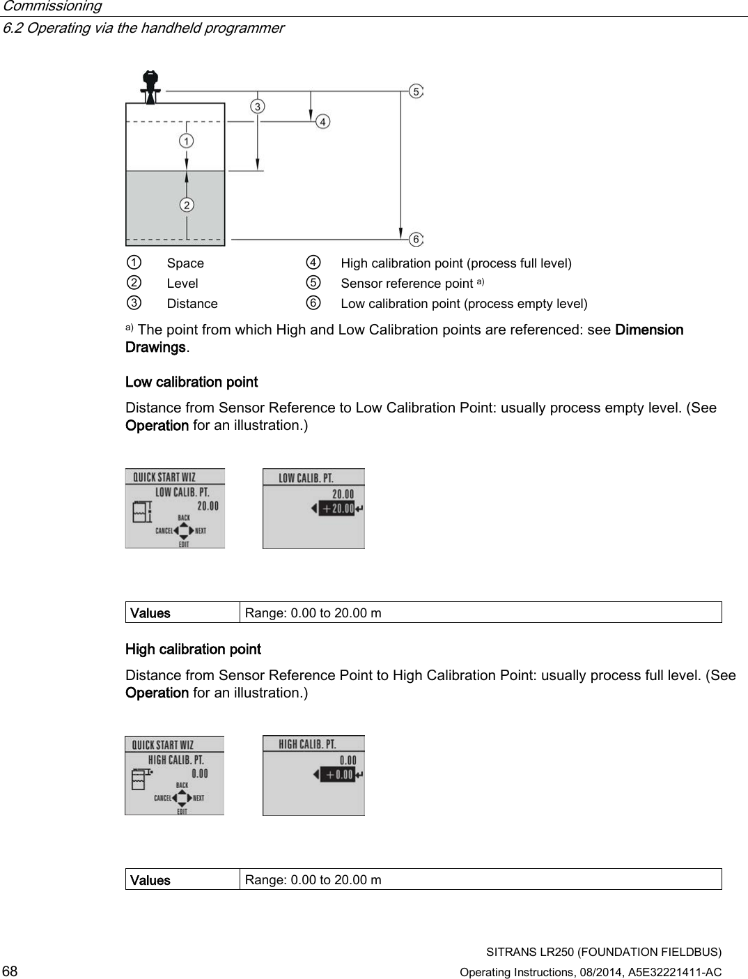
Siemens Canada Siemens Milltronics Process Instruments LR250 SITRANS LR 250 TANK LEVEL PROBING RADAR User Manual SITRANS LR250 FOUNDATION FIELDBUS
Siemens Canada Ltd. - Siemens Milltronics Process Instruments SITRANS LR 250 TANK LEVEL PROBING RADAR SITRANS LR250 FOUNDATION FIELDBUS
Contents
User Manual 3
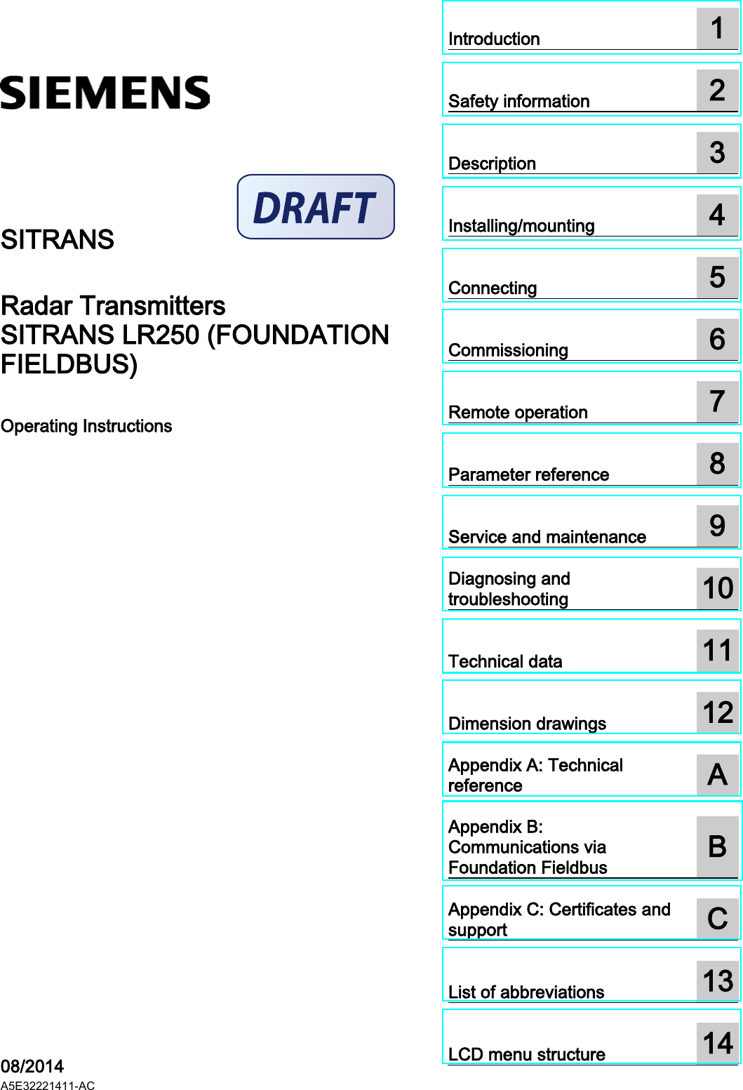

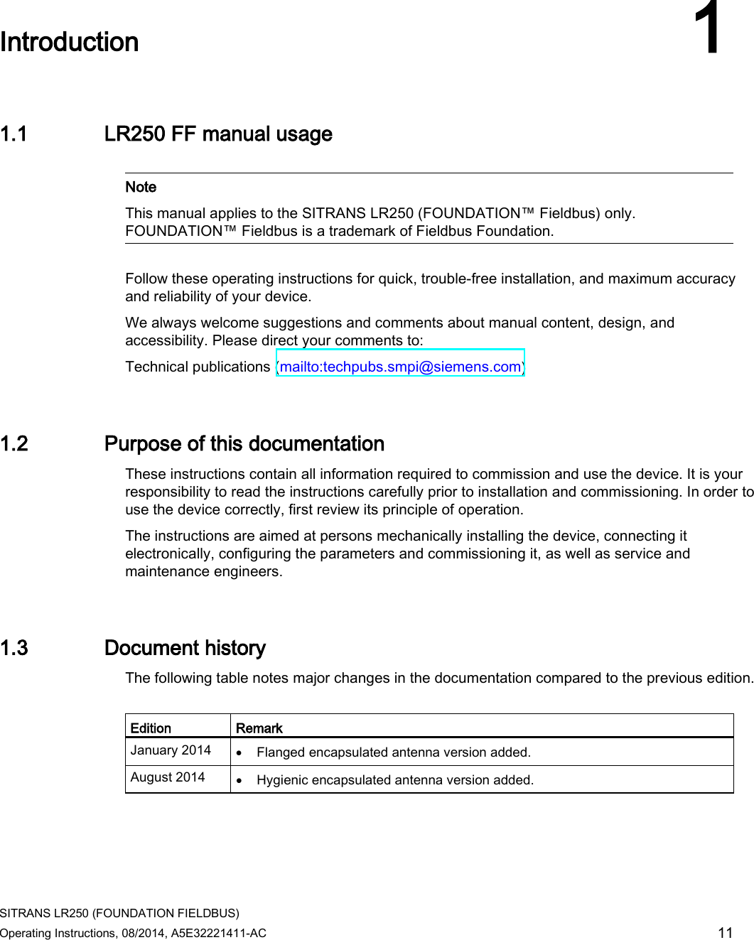
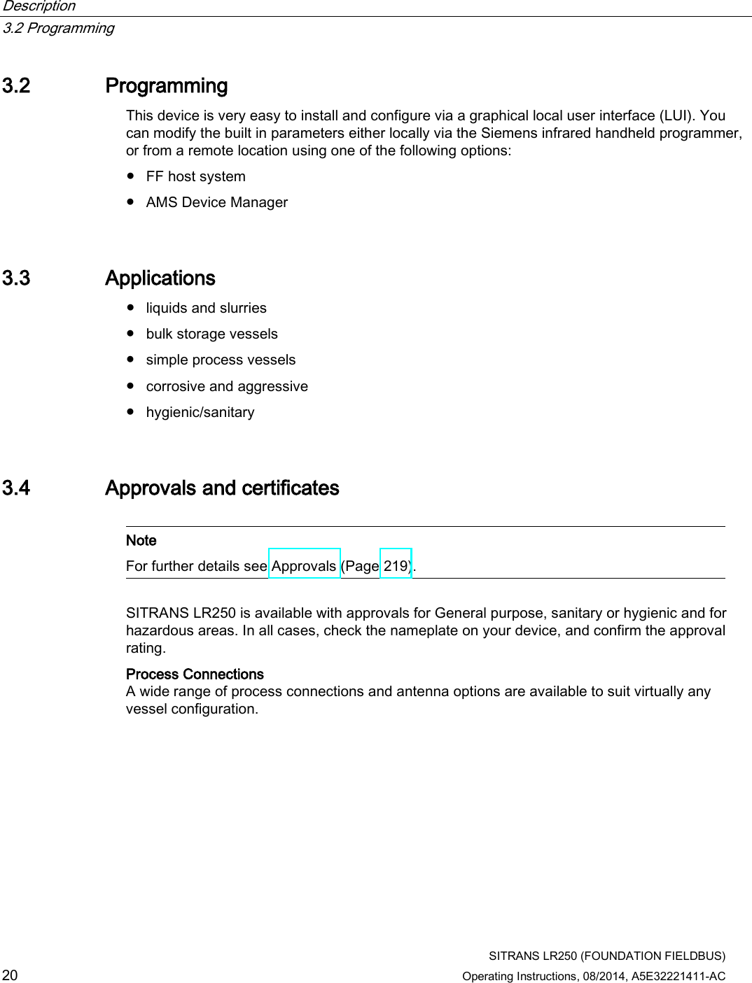
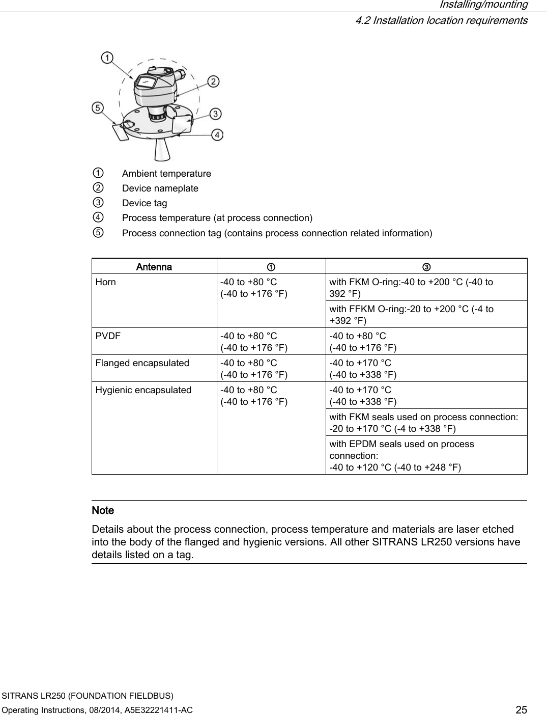
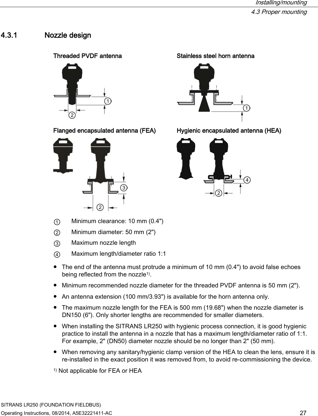
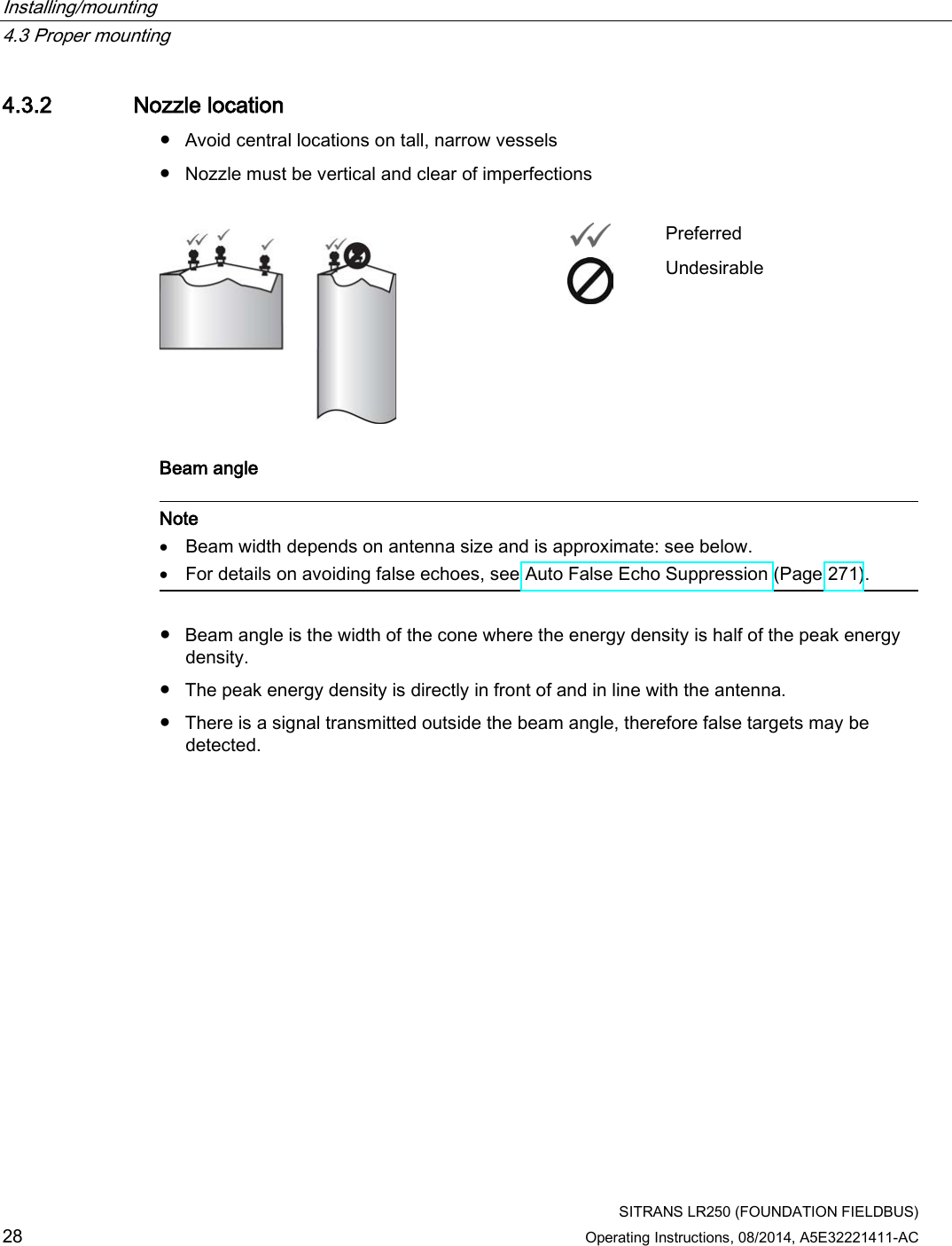
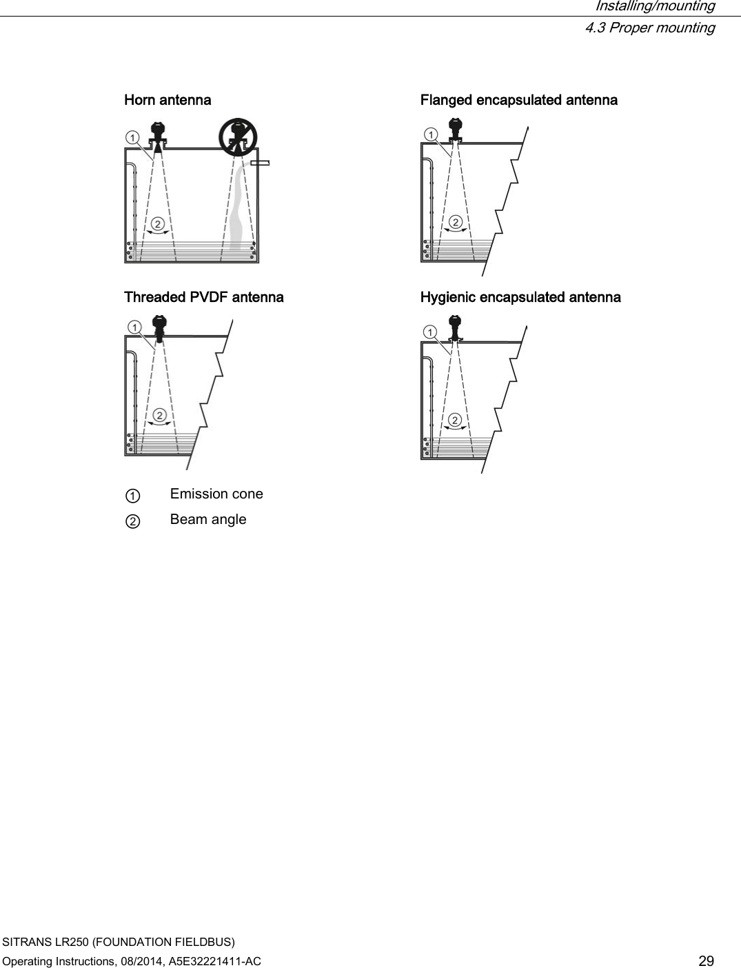
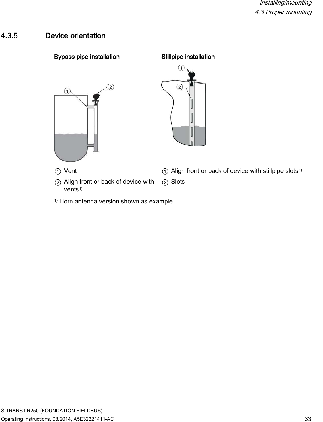
![Installing/mounting 4.3 Proper mounting SITRANS LR250 (FOUNDATION FIELDBUS) 30 Operating Instructions, 08/2014, A5E32221411-AC Emission cone type and beam angle Antenna type Antenna size Beam angle Horn 1.5" 19° 2" 15° 3" 10° 4" 8° Threaded PVDF 19° Process connection size Process connection type Flanged encapsulated 2" Class 150 ASME B16.5 12.8° 3, 4, 6" Class 150 ASME B16.5 9.6° 50A 10K JIS B 2220 12.8° 80A/100A/150A 10K JIS B 2220 9.6° DN50 PN10/16 EN1092-1 12.8° DN80/DN100/DN150 PN10/16 EN1092-1 9.6° Hygienic encapsulated 2" Sanitary Clamp according to ISO 2852 12.8° 3, 4" 9.6° DN50 Aseptic/Hygienic nozzle/slotted nut according to DIN 11864-1 [Form A] 12.8° DN80/DN100 9.6° DN50 Aseptic/Hygienic flanged according to DIN 11864-2 [Form A] 12.8° DN80/DN100 9.6° DN50 Aseptic/Hygienic Clamp according to DIN 11864-3 [Form A] 12.8° DN80/DN100 9.6° DN50 Hygienic nozzle/slotted nut according to DIN 11851 12.8° DN80/DN100 9.6° Type F (50 mm) and Type N (68 mm) Tuchenhagen Varivent 12.8° Emission cone ● Keep emission cone free of interference from obstructions such as ladders, pipes, I-beams, or filling streams. Access for programming ● Provide easy access for viewing the display and programming via the handheld programmer.](https://usermanual.wiki/Siemens-Canada-Siemens-Milltronics-Process-Instruments/LR250.User-Manual-3/User-Guide-2277918-Page-30.png)

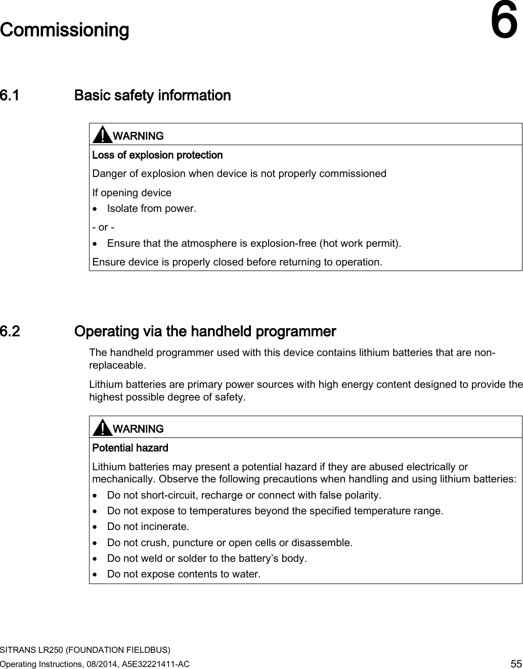
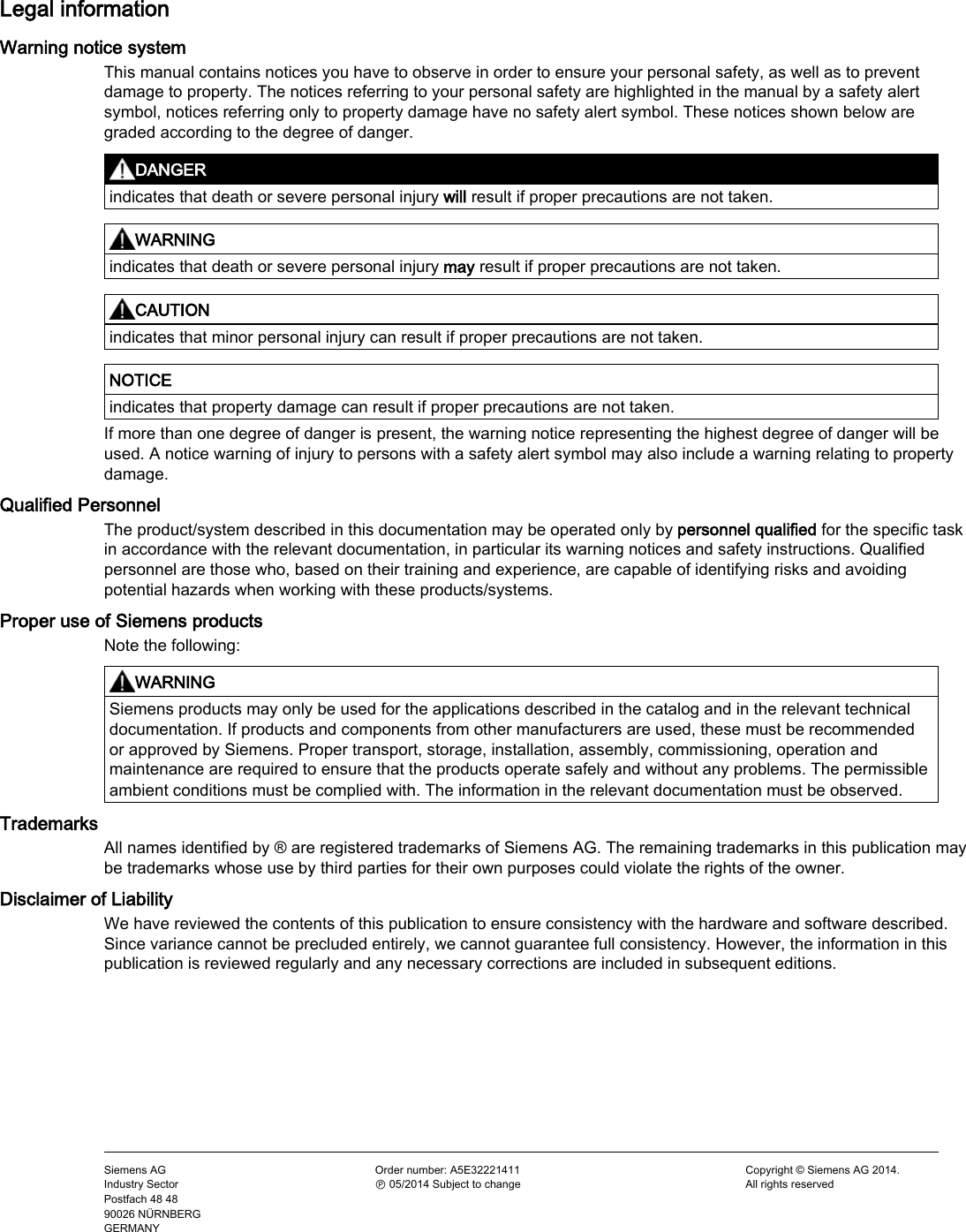
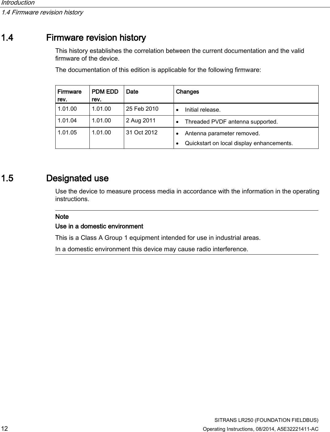
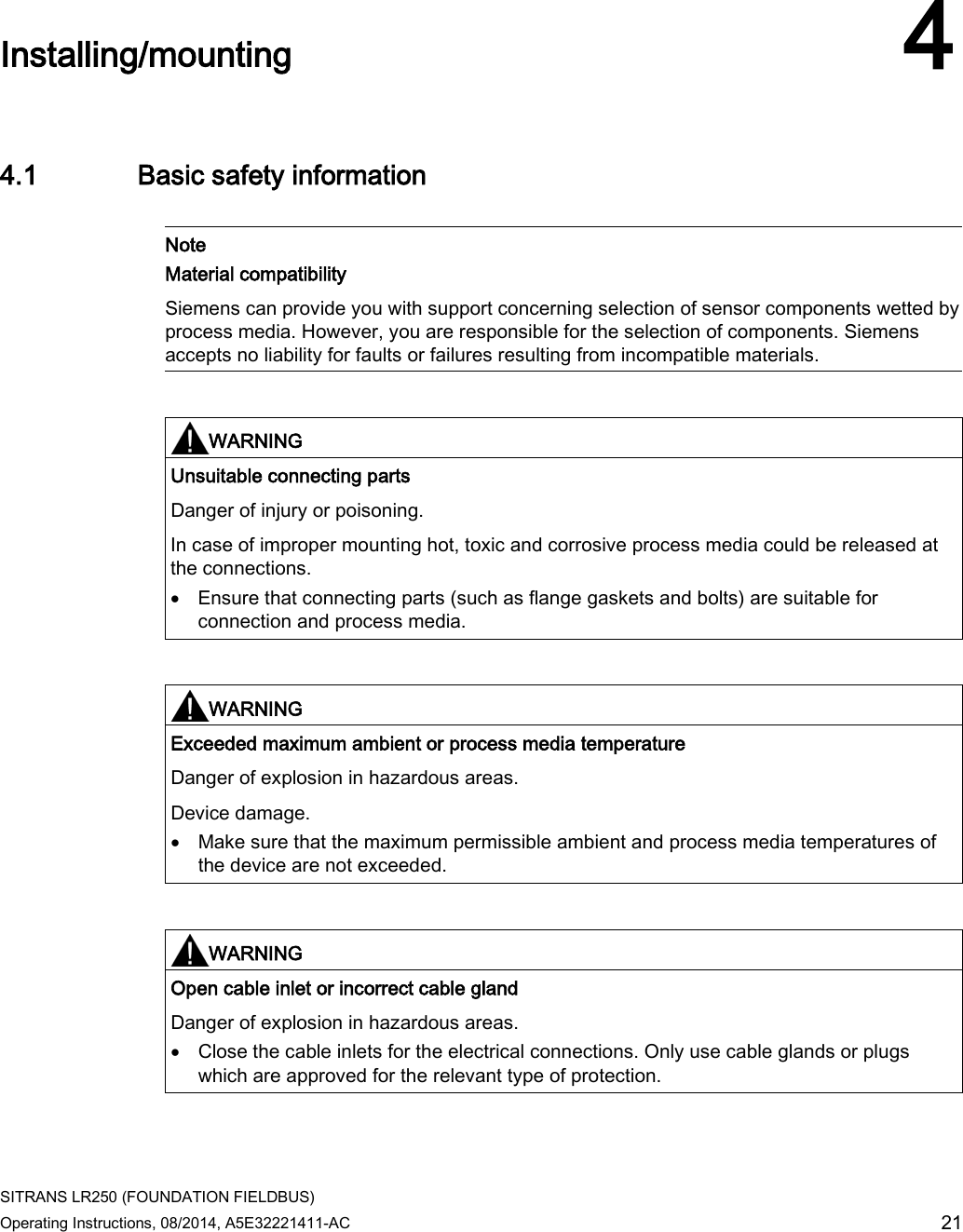
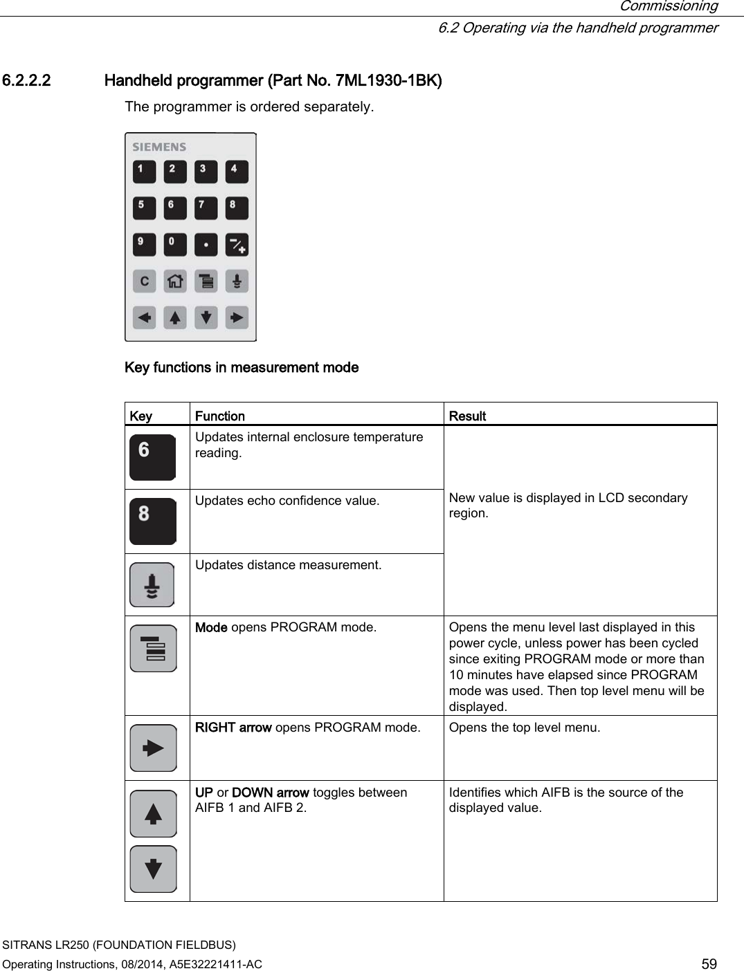
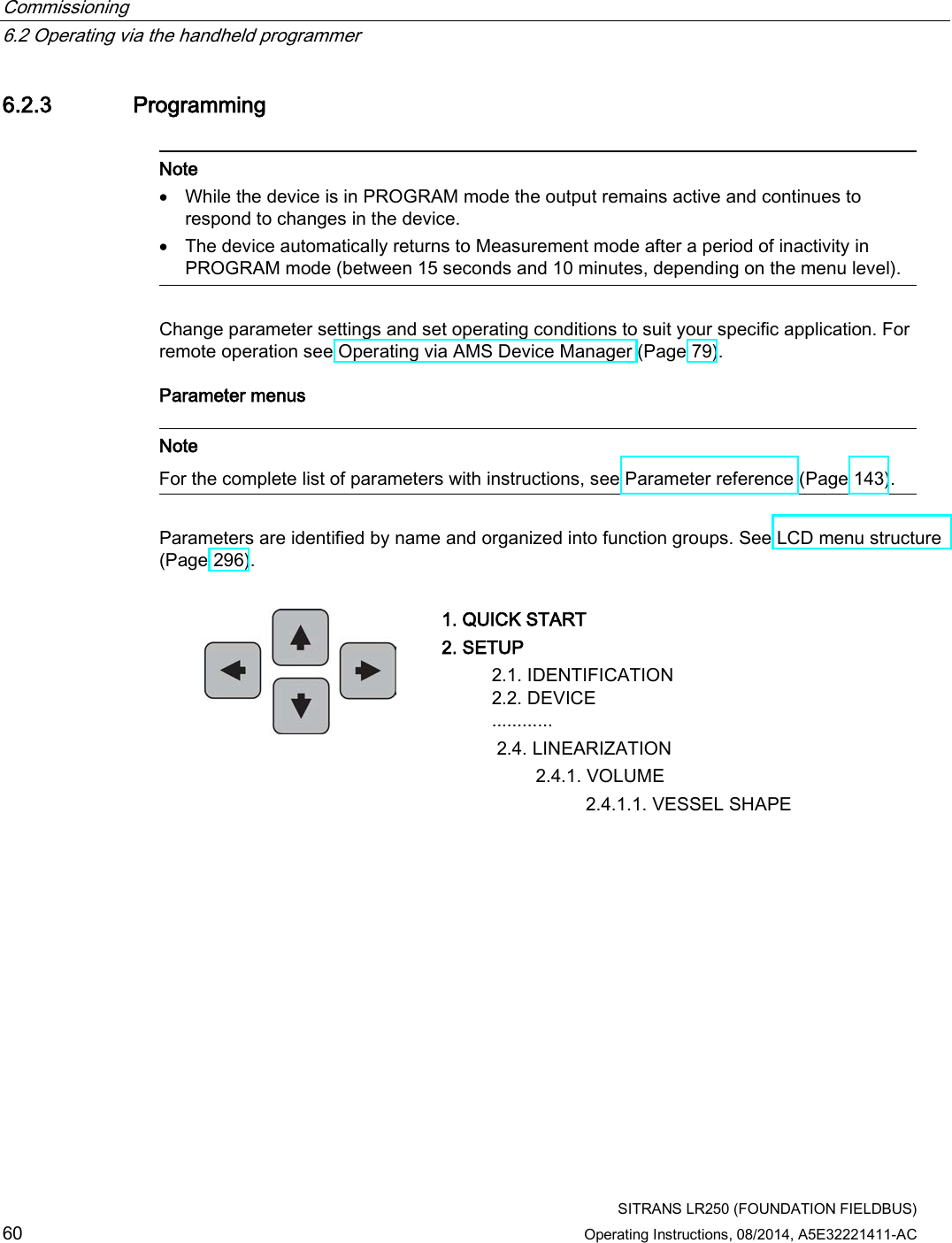
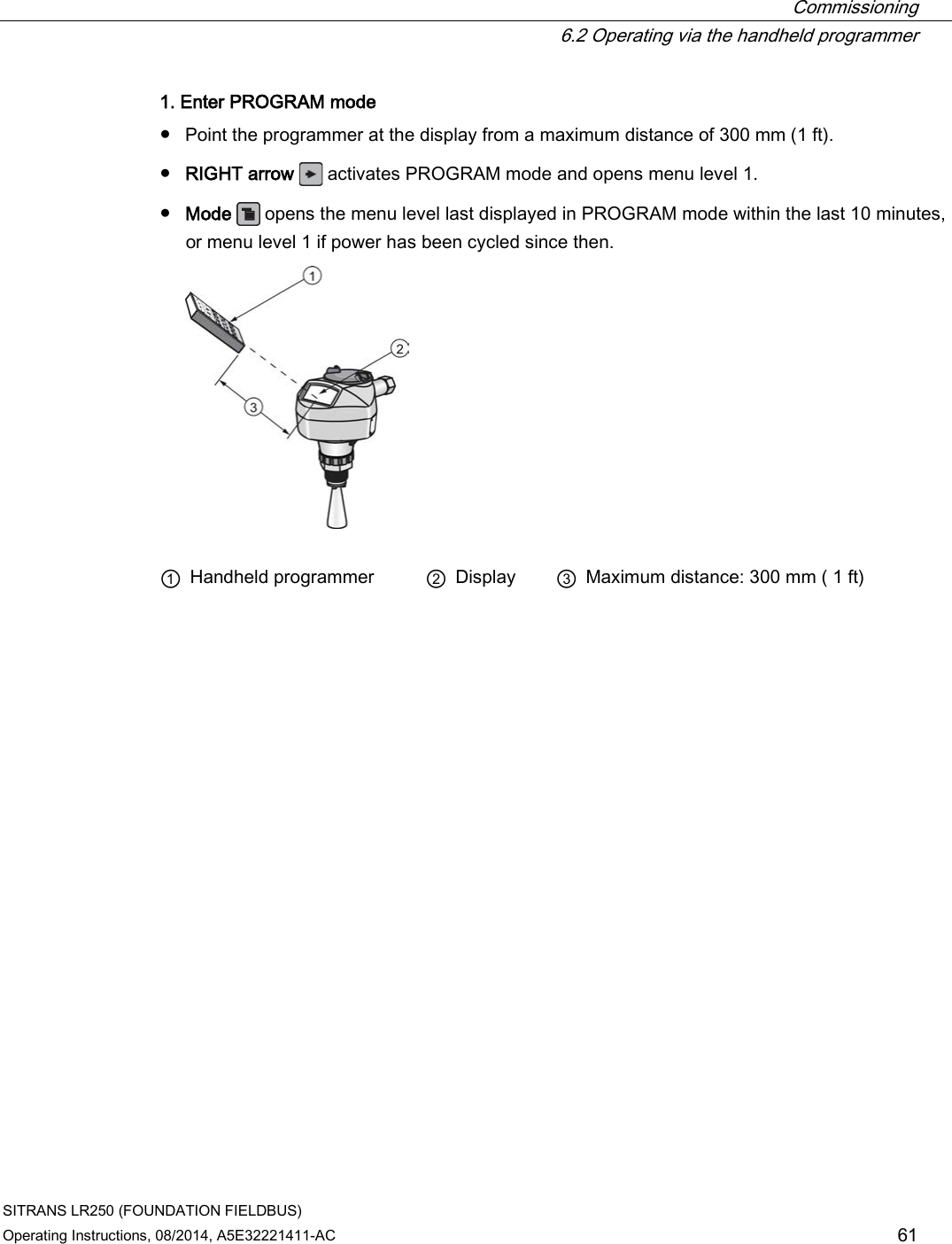
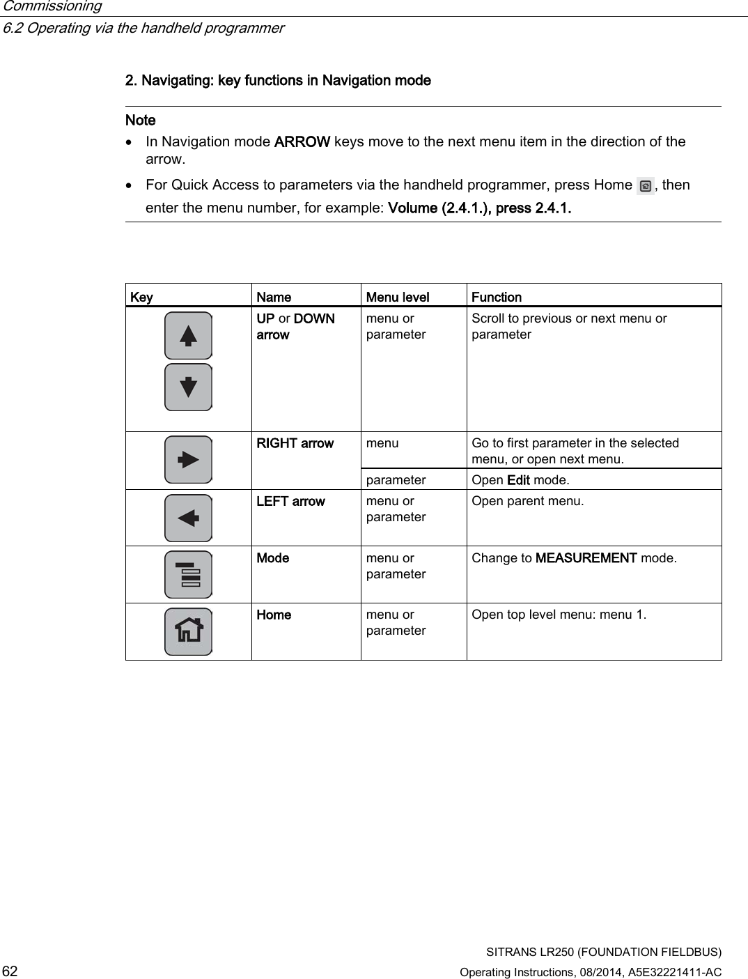
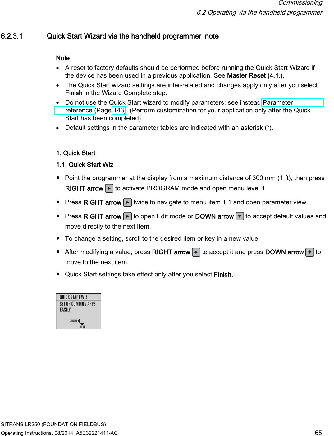
![Commissioning 6.2 Operating via the handheld programmer SITRANS LR250 (FOUNDATION FIELDBUS) 56 Operating Instructions, 08/2014, A5E32221411-AC 6.2.1 Power up Power up the device. A transition screen showing first the Siemens logo and then the current firmware revision is displayed while the first measurement is being processed. SITRANS LR250 automatically starts up in Measurement mode. The first time the device is configured, you will be prompted to select a language (English, German, French, Spanish or Chinese).To change the language again, see Language (7.). Press Mode to toggle between Measurement and Program mode. [If the SITRANS LR250 FF is to be used in an FF application, configure using a network configuration tool, such as DeltaV or NI-FBUS Configurator. See Quick Start Wizard via AMS Device Manager (Page 85).] Follow these steps to configure the device via the LUI: ● Complete the Quick Start Wizard [see Quick Start Wizard via the handheld programmer (Page 65)]. Completing the Quick Start Wizard or writing any parameter via the LUI causes the device to begin measuring. The Resource Block (RES) and Level Transducer Block (LTB) will move to Automatic mode. ● AIFB 1 and AIFB 2 will remain Out of Service (as displayed on the LCD). These blocks can only be configured and scheduled using a network configuration tool. For more details, see System Integration in manual Foundation Fieldbus for Level Instruments (7ML19985MP01). Note The last step of the Quick Start run from the LUI will place the RESOURCE block in Automatic mode. 6.2.2 Handheld programmer functions The radar device carries out its level measurement tasks according to settings made via parameters. The settings can be modified locally via the Local User Interface (LUI) which consists of an LCD display and a handheld programmer. A Quick Start Wizard provides an easy step-by-step procedure to configure the device for a simple application. Access the wizards: ● locally [see Quick Start Wizard via the handheld programmer (Page 65)] ● or from a remote location [see Quick Start Wizard via AMS Device Manager (Page 85)] For more complex setups see Application Examples (Page 71), and for the complete range of parameters see Parameter Reference (Page 143).](https://usermanual.wiki/Siemens-Canada-Siemens-Milltronics-Process-Instruments/LR250.User-Manual-3/User-Guide-2277918-Page-56.png)
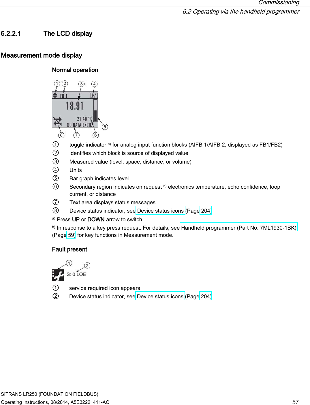
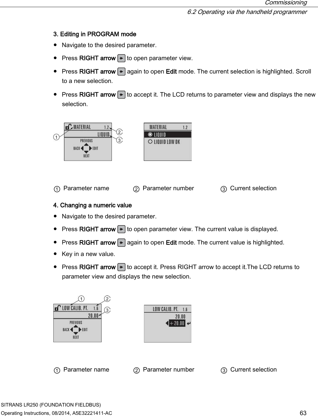
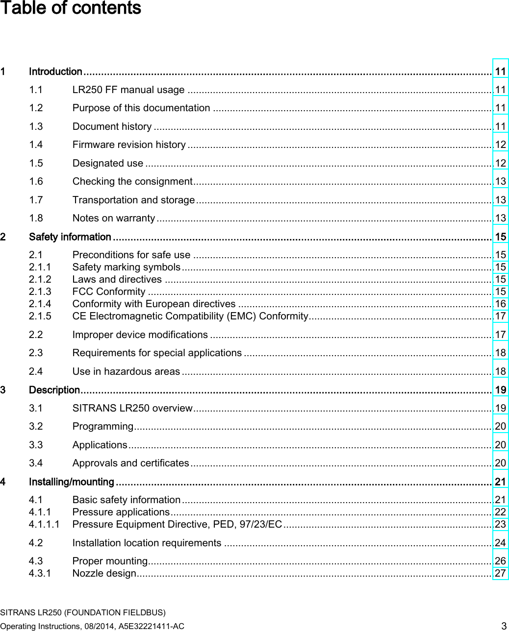
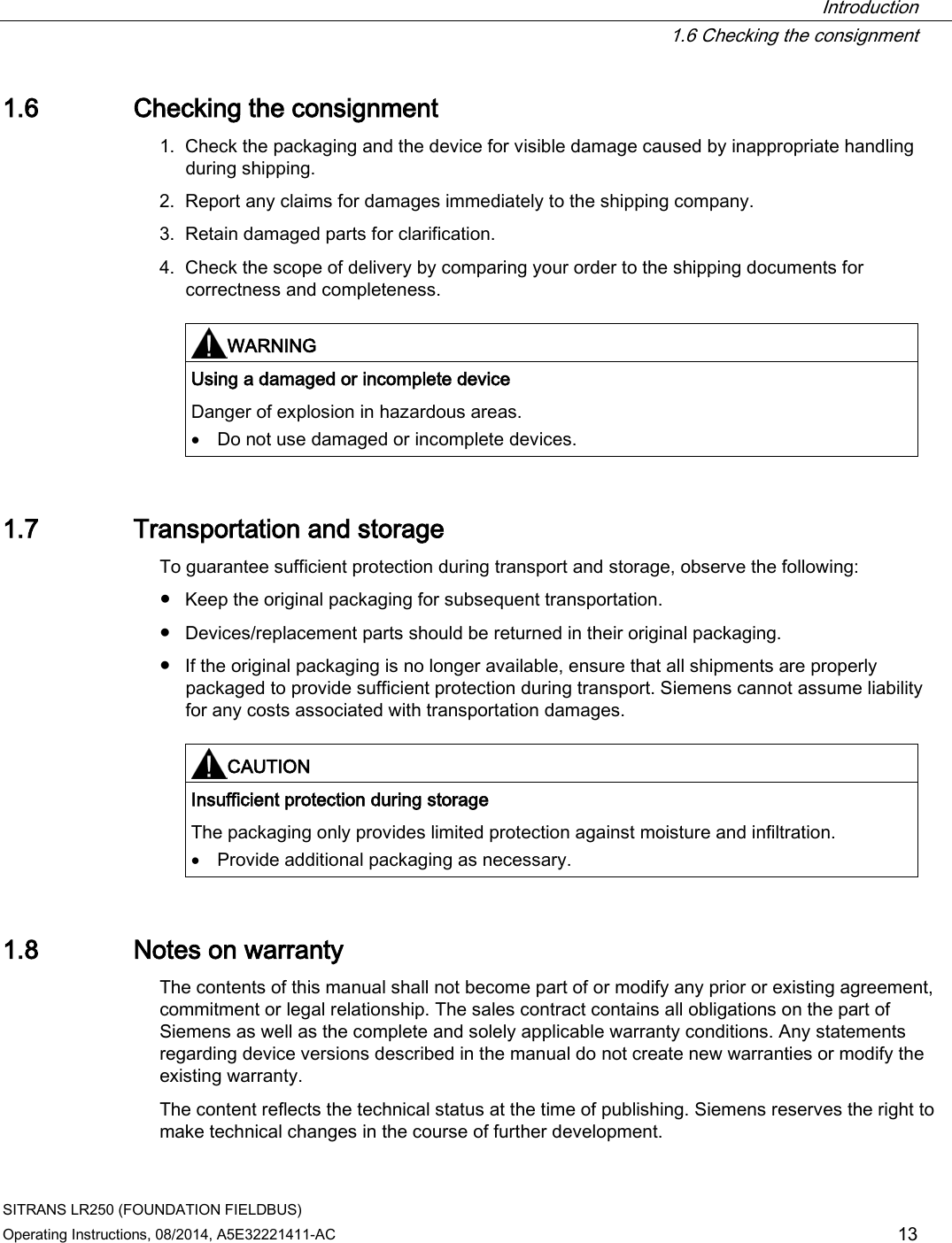
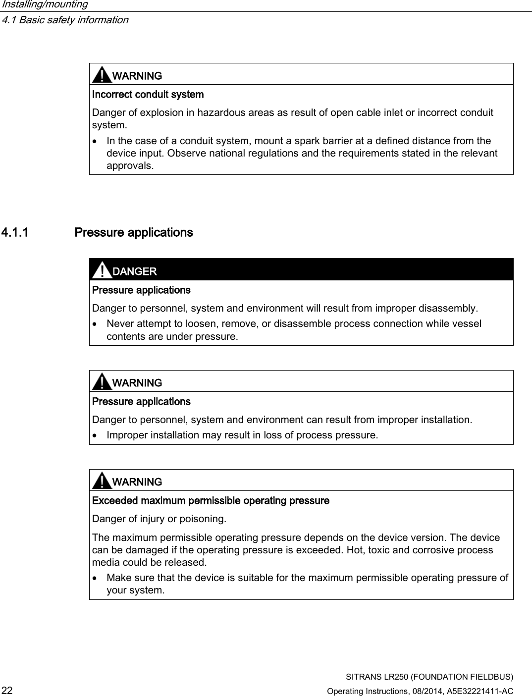
![Commissioning 6.2 Operating via the handheld programmer SITRANS LR250 (FOUNDATION FIELDBUS) 64 Operating Instructions, 08/2014, A5E32221411-AC Key functions in edit mode Key Name Function UP or DOWN arrow Selecting options Scrolls to item. Numeric editing • Increments or decrements digits • Toggles plus and minus sign RIGHT arrow Selecting options • Accepts the data (writes the parameter) • Changes from Edit to Navigation mode Numeric editing • Moves cursor one space to the right • or, with cursor on Enter sign, accepts the data and changes from Edit to Navigation mode LEFT arrow: Selecting options Cancels Edit mode without changing the parameter. Numeric editing • Moves cursor to plus/minus sign if this is the first key pressed • or moves cursor one space to the left • or with cursor on the Enter sign, cancels the entry. Clear Numeric editing Erases the display. Decimal point Numeric editing • Enters a decimal point • Captures the current path [see Secondary Value (4.11.)] Plus or minus sign Numeric editing Changes the sign of the entered value. to Numeral Numeric editing Enters the corresponding character.](https://usermanual.wiki/Siemens-Canada-Siemens-Milltronics-Process-Instruments/LR250.User-Manual-3/User-Guide-2277918-Page-64.png)
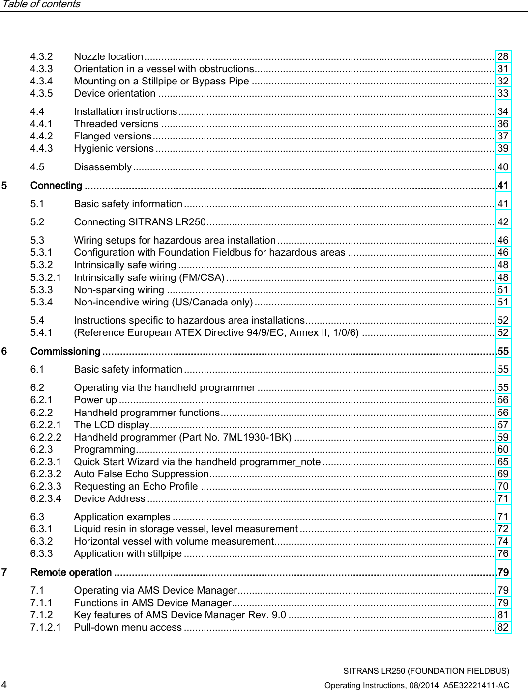
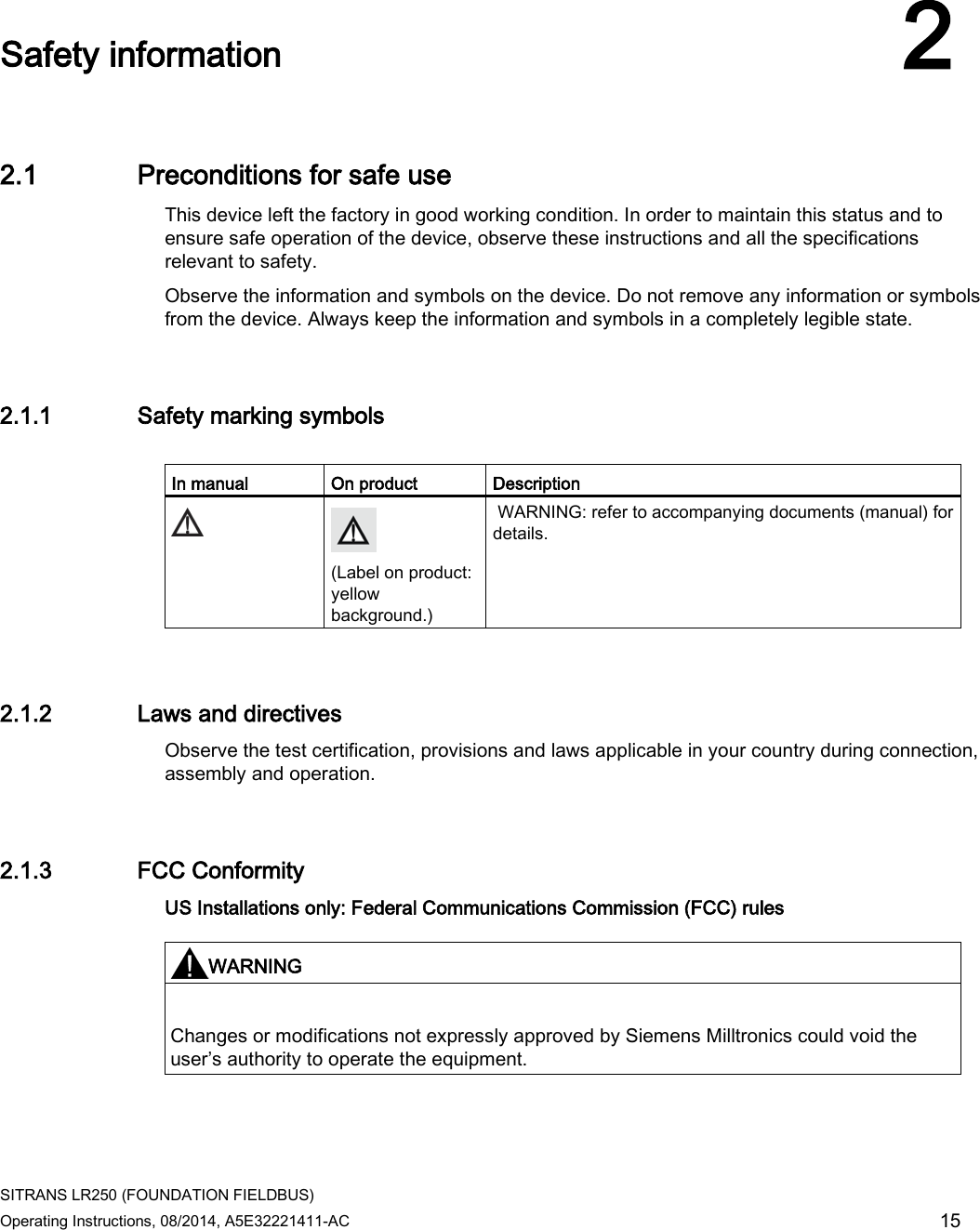
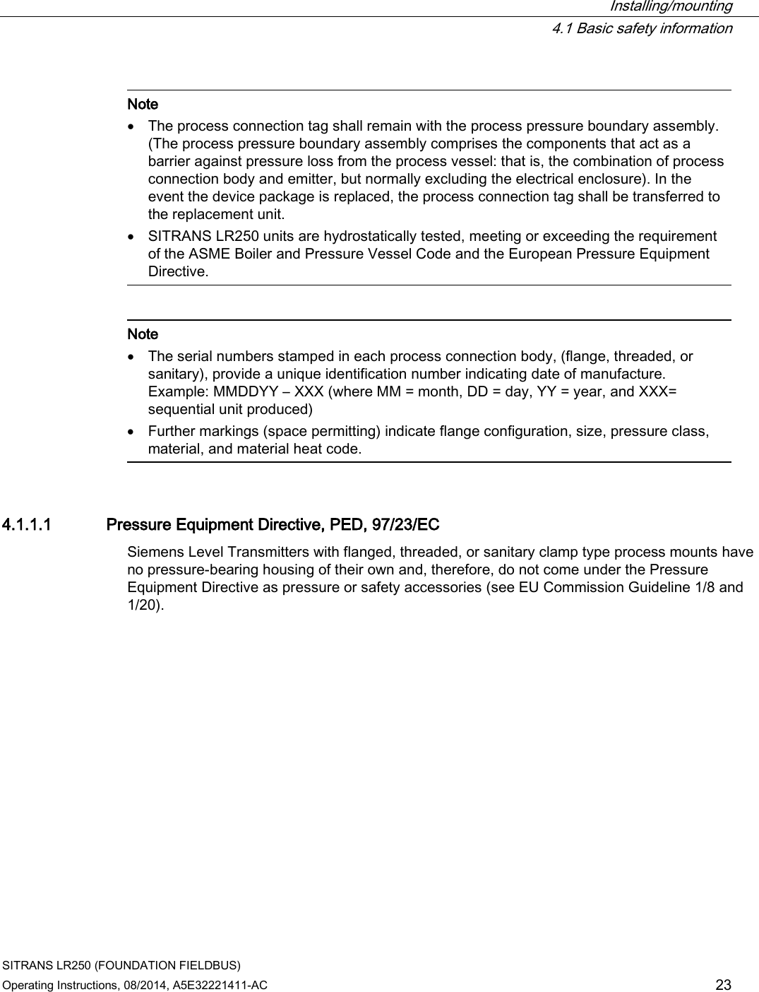
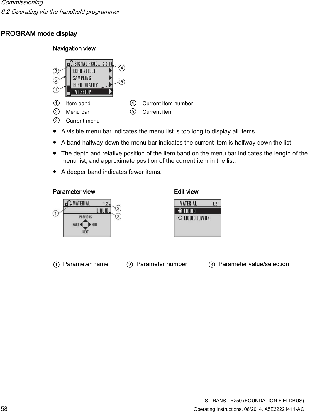
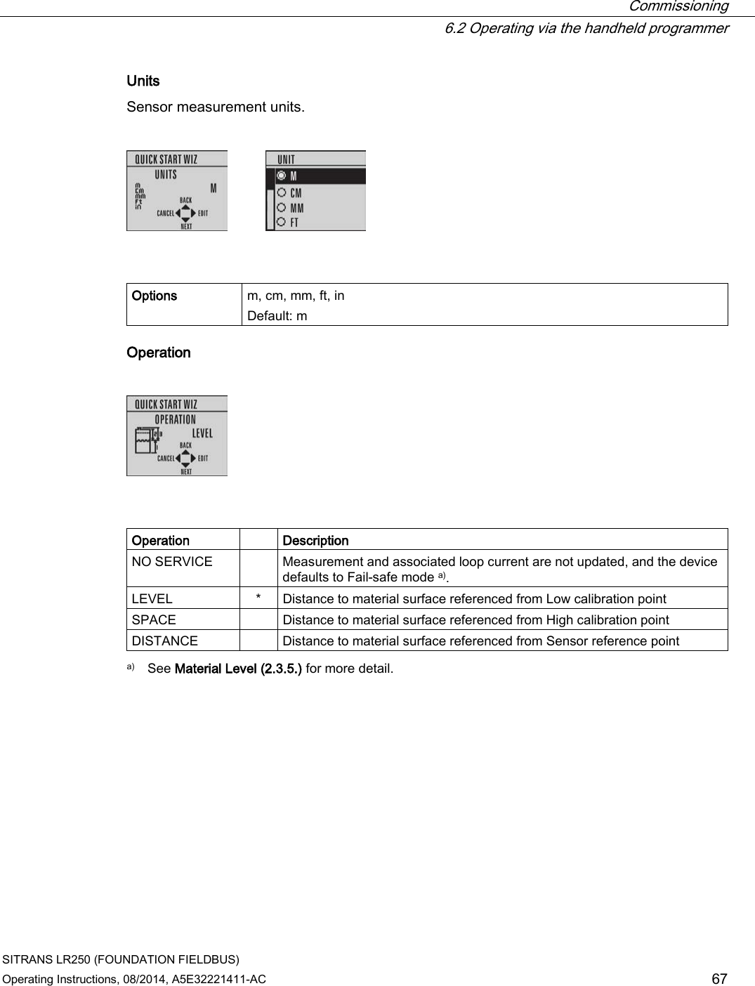
![Commissioning 6.2 Operating via the handheld programmer SITRANS LR250 (FOUNDATION FIELDBUS) 66 Operating Instructions, 08/2014, A5E32221411-AC Material Selects the appropriate echo processing algorithms for the material [see Position Detect (2.5.7.2.) for more detail]. Options * LIQUID LIQUID LOW DK a) (low dielectric liquid – CLEF algorithm enabled) a) dK < 3.0 Response rate Sets the reaction speed of the device to measurement changes in the target range. Use a setting just faster than the maximum filling or emptying rate (whichever is greater). Options Response rate (2.3.8.1.) Fill rate per Minute (2.3.8.2.)/ Empty rate per Minute (2.3.8.3.) * SLOW 0.1 m/min (0.32 ft/min) MED 1.0 m/min (3.28 ft/min) FAST 10.0 m/min (32.8 ft/min)](https://usermanual.wiki/Siemens-Canada-Siemens-Milltronics-Process-Instruments/LR250.User-Manual-3/User-Guide-2277918-Page-66.png)
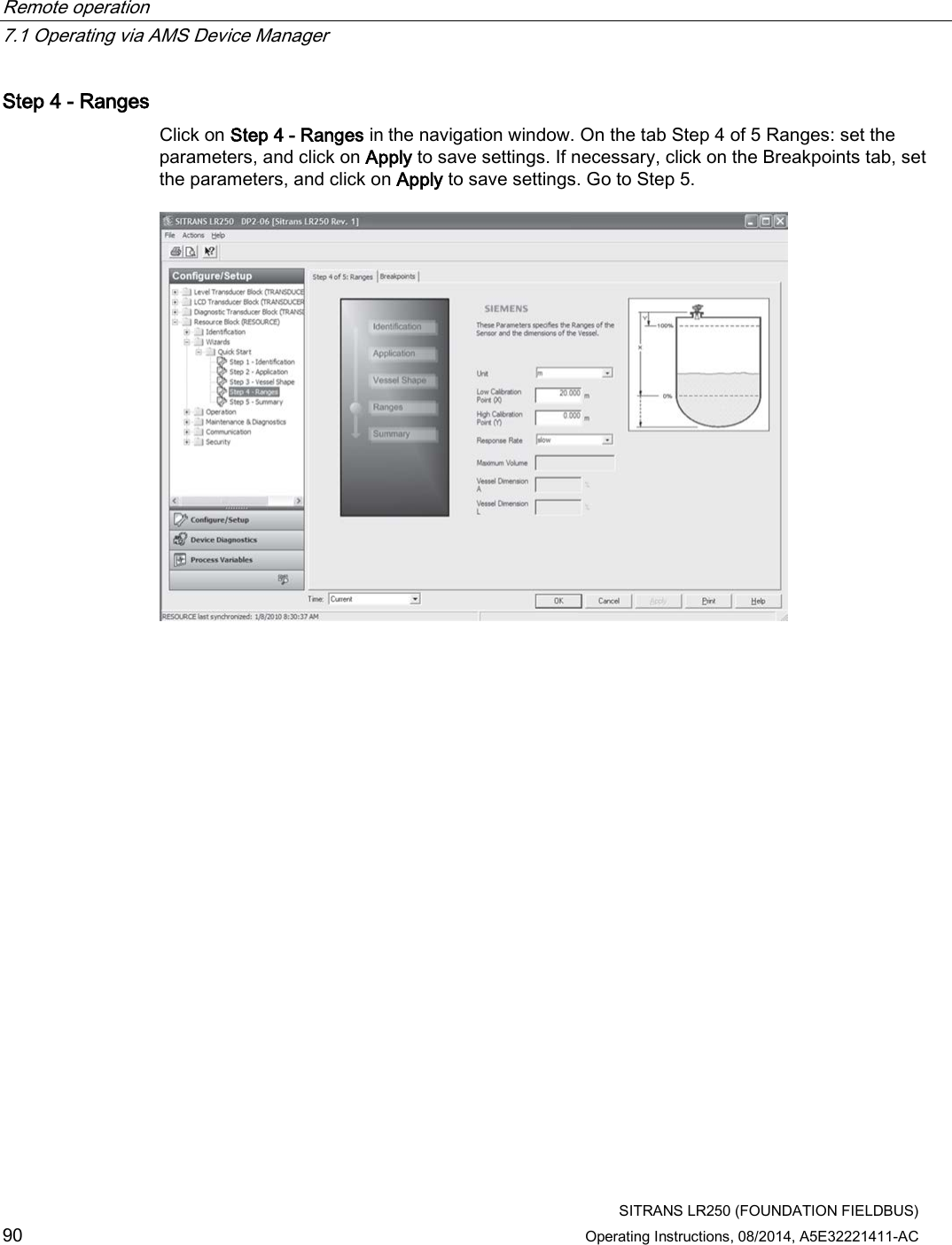
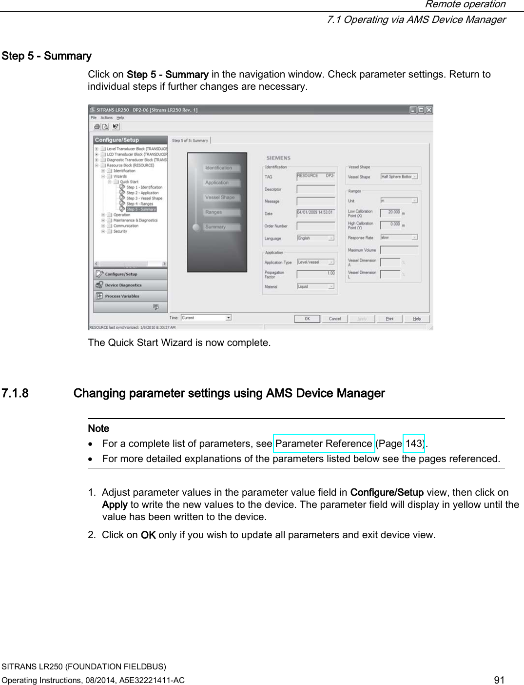
![Remote operation 7.1 Operating via AMS Device Manager SITRANS LR250 (FOUNDATION FIELDBUS) Operating Instructions, 08/2014, A5E32221411-AC 85 7.1.6 Sensor calibration The LR250 FF does not need to be calibrated, only configured using the Quick Start Wizard below. 7.1.7 Configuring a new device Configure a new device using the Quick Start Wizard, found in the Resource Block of the function group Configure/Setup. 7.1.7.1 Quick Start Wizard via AMS Device Manager The Quick Start Wizard groups together all the settings you need to configure a device for most applications. Please consult the operating instructions or online help for details on using AMS Device Manager. Note Use Quick Start Wizard via AMS Device Manager for initial configuration of a device on an FF network. If device is not on an FF network, initial configuration should be completed via the Quick Start Wizard from the LUI. [See Quick Start Wizard via the handheld programmer (Page 65).]](https://usermanual.wiki/Siemens-Canada-Siemens-Milltronics-Process-Instruments/LR250.User-Manual-3/User-Guide-2277918-Page-85.png)
![Remote operation 7.1 Operating via AMS Device Manager SITRANS LR250 (FOUNDATION FIELDBUS) 92 Operating Instructions, 08/2014, A5E32221411-AC 7.1.9 Configure/Setup (Level Transducer Block-LTB) 7.1.9.1 Identification (LTB) Navigate to Configure/Setup > LTB > Identification. Identification: ● TAG: Read only. Description for the associated block: device tag prefixed by block type. ● Descriptor [see Descriptor (2.1.2.)] ● Transducer Block Type: Read only. Identifies the type of transducer block. ● Strategy: Used to identify grouping of blocks. ● Plant Unit: The identification number of the plant unit. For example, can be used in the host for sorting alarms.](https://usermanual.wiki/Siemens-Canada-Siemens-Milltronics-Process-Instruments/LR250.User-Manual-3/User-Guide-2277918-Page-92.png)
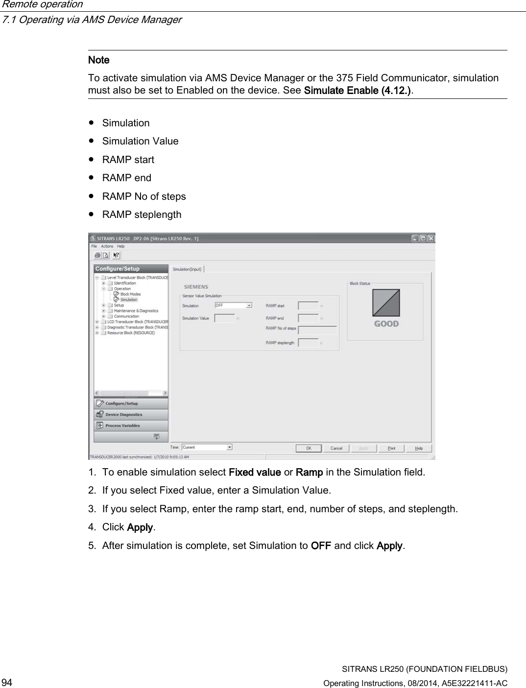
![Remote operation 7.1 Operating via AMS Device Manager SITRANS LR250 (FOUNDATION FIELDBUS) Operating Instructions, 08/2014, A5E32221411-AC 93 7.1.9.2 Operation (LTB) Navigate to Configure/Setup > LTB > Operation. Click on Block Modes to open the dialog window for access to: Block Modes: ● Actual Mode: This is the current mode of the block, which may differ from the target based on operating conditions. Its value is calculated as part of the block execution. ● Target Mode [see Mode (2.6.2.)] ● Permitted Mode: Defines the modes that are allowed for an instance of the block. The permitted mode is configured based on application requirements. ● Normal Mode: This is the mode that the block should be set to during normal operating conditions. Click on Simulation to open the dialog window for access to: Simulation (Input) Allows you to simulate the sensor value which is input to the Level Transducer Block. This tests everything between the Level Transducer Block and Output.](https://usermanual.wiki/Siemens-Canada-Siemens-Milltronics-Process-Instruments/LR250.User-Manual-3/User-Guide-2277918-Page-93.png)
![Remote operation 7.1 Operating via AMS Device Manager SITRANS LR250 (FOUNDATION FIELDBUS) Operating Instructions, 08/2014, A5E32221411-AC 95 7.1.9.3 Setup (LTB) Sensor (LTB) Navigate to Configure/Setup > LTB > Setup and click on Sensor for access to: General [see Sensor (2.3.) for details] ● Unit [see Unit (2.3.1.)] ● Level Unit [see Level Unit (2.3.2.)] ● Temperature Unit [see Temperature Units (2.3.4.)] ● PV (Volume/Level) Unit [see PV (volume/level) Units (2.3.3.)] ● Application Type (available only via AMS Device Manager)](https://usermanual.wiki/Siemens-Canada-Siemens-Milltronics-Process-Instruments/LR250.User-Manual-3/User-Guide-2277918-Page-95.png)
![Remote operation 7.1 Operating via AMS Device Manager SITRANS LR250 (FOUNDATION FIELDBUS) 96 Operating Instructions, 08/2014, A5E32221411-AC Defines the application type. Values Level/vessel (default) Level/stillpipe Level/bypass pipe Volume/vessel Volume/stillpipe Volume/bypass pipe ● Material [see Material (2.3.5.)] ● Loss of Echo Timer (see Loss of Echo (LOE) Timer (2.3.6.)] Calibration [see Calibration (2.3.7.) for details] ● Low Calibration Point [see Low Calibration Point (2.3.7.1.)] ● High Calibration Point [see High Calibration Point 2.3.7.2.)] ● Sensor Offset [see Sensor Offset (2.3.7.3.)] ● Low Level Point [see Low Level Point (2.3.7.4.)] ● High Level Point [see High Level Point (2.3.7.5)] ● Level Offset [see Level Offset (2.3.7.6.)] Rate [see Rate (2.3.8.)] ● Response Rate [see Response Rate (2.3.8.1.)] ● Fill Rate per Minute [see Fill Rate per Minute (2.3.8.2.)] ● Empty Rate per Minute [see Empty Rate per Minute (2.3.8.3.)]](https://usermanual.wiki/Siemens-Canada-Siemens-Milltronics-Process-Instruments/LR250.User-Manual-3/User-Guide-2277918-Page-96.png)
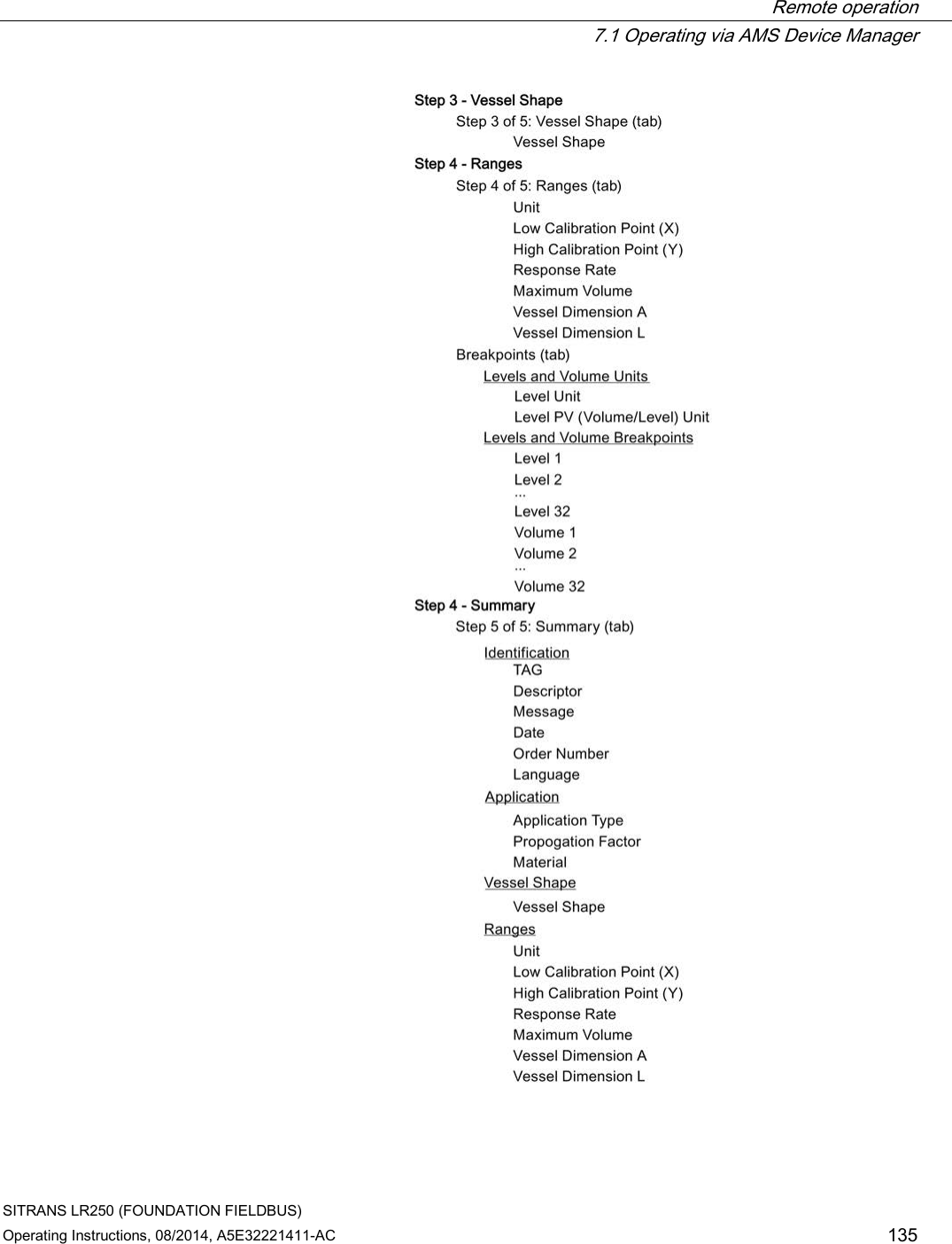
![Remote operation 7.1 Operating via AMS Device Manager SITRANS LR250 (FOUNDATION FIELDBUS) Operating Instructions, 08/2014, A5E32221411-AC 97 7.1.9.4 Linearization (LTB) You can use the linearization feature to define a more complex vessel shape and enter up to 32 level breakpoints where the corresponding volume is known. See Linearization (2.4.). Navigate to Configure/Setup > LTB > Setup > Linearization and click on Linearization. Click on the Vessel Shape tab to access the parameters listed: Vessel Shape ● Vessel Shape [see Vessel Shape (2.4.1.1.)] Vessel Dimensions ● Maximum Volume [see Maximum Volume (2.4.1.2.)] ● Vessel Dimension A [see Dimension A (2.4.1.3.)] ● Vessel Dimension L [see Dimension L (2.4.1.4.)] OR Click on Breakpoints tab for access to level and volume breakpoints. Note This parameter becomes accessible only after Linearization Table has been selected in Vessel Shape above.](https://usermanual.wiki/Siemens-Canada-Siemens-Milltronics-Process-Instruments/LR250.User-Manual-3/User-Guide-2277918-Page-97.png)
![Remote operation 7.1 Operating via AMS Device Manager SITRANS LR250 (FOUNDATION FIELDBUS) 98 Operating Instructions, 08/2014, A5E32221411-AC Level and Volume Breakpoints [see XY Index (2.4.1.5.)] ● Level 1 .... Level 32 ● Volume 1 ... Volume 32 ● Vessel Shape 1. The default for level values is percent: if you want to select units instead, go to Configure/Setup > LTB > Setup > Sensor > Level Unit, and select the desired unit. 2. Go to Configure/Setup > LTB > Setup > Sensor > PV (Volume/Level) Unit, and select the desired volume units. 3. From the Vessel Shape tab of Configure/Setup > LTB > Setup > Linearization, select Linearization Table option in the Vessel Shape field. 4. Click on the Breakpoints tab and enter values for level and volume breakpoints in table. The values corresponding to 100% and 0% levels must be entered. The breakpoints can be ordered from top to bottom, or the reverse. After completing the above steps you will need to configure AIFB 1 and/or AIFB 2. [See AIFB 1 (2.6.) and AIFB 2 (2.7.)]](https://usermanual.wiki/Siemens-Canada-Siemens-Milltronics-Process-Instruments/LR250.User-Manual-3/User-Guide-2277918-Page-98.png)
![Remote operation 7.1 Operating via AMS Device Manager SITRANS LR250 (FOUNDATION FIELDBUS) Operating Instructions, 08/2014, A5E32221411-AC 99 7.1.9.5 Signal processing Signal Processing (LTB) Note For more detailed explanations of the parameters listed below see the pages referenced. General Navigate to Configure/Setup > LTB > Setup > Signal Processing and click on General for access to: Range [see Signal Processing (2.5.)] ● Near Range [see Near Range (2.5.1.)] ● Far Range [see Far Range (2.5.2.)] ● Propogation Factor [see Propogation Factor (2.5.3.)] ● Minimum Sensor Value [see Minimum Sensor Value (2.5.4.)] ● Maximum Sensor Value [see Maximum Sensor Value (2.5.5.)]](https://usermanual.wiki/Siemens-Canada-Siemens-Milltronics-Process-Instruments/LR250.User-Manual-3/User-Guide-2277918-Page-99.png)
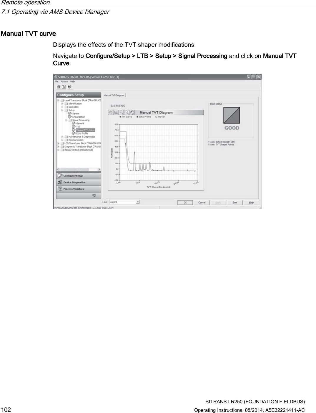
![Remote operation 7.1 Operating via AMS Device Manager SITRANS LR250 (FOUNDATION FIELDBUS) 100 Operating Instructions, 08/2014, A5E32221411-AC Echo Select [see Echo Select (2.5.7.)] ● Algorithm [see Algorithm (2.5.7.1.)] ● Position Detect [see Position Detect (2.5.7.2.)] ● Echo Threshold [see Echo Threshold (2.5.7.3.)] ● CLEF Range [see CLEF (Contrained Leading Edge Fit) Range (2.5.7.4.)] Sampling [see Sampling (2.5.8.)] ● Echo Lock [see Echo Lock (2.5.8.1.)] ● Sampling Up [see Up Sampling (2.5.8.2.)] ● Sampling Down [see Down Sampling (2.5.8.3.)] Echo Quality [see Echo Quality (2.5.9.)] ● Confidence [see Confidence (2.5.9.1.)] ● Echo Strength [see Echo Strength (2.5.9.2.)] ● Noise Average Displays the average ambient noise (in dB above 1 μV rms) of a noise profile. Noise level is a combination of transient noise and receiving circuitry. After a measurement, the values from the previous noise shot will be displayed. TVT (time varying threshold) A time-varying curve that determines the threshold level above which echoes are determined to be valid. Modify the TVT to screen out false echoes [see Time Varying Threshold (TVT) (Page 266), and Auto False Echo Suppression (2.5.10.1.)]. Navigate to Configure/Setup > LTB > Setup > Signal Processing and click on TVT. Click on one of the two tabs to access the parameters listed: TVT Setup ● Auto False Echo Suppression [see Auto False Echo Suppression (2.5.10.1.)] ● Auto False Echo Suppression Range [see Auto False Echo Suppression Range (2.5.10.2.)] ● Hover Level [see Hover Level (2.5.10.3.)] ● Shaper Mode [see Shaper Mode (2.5.10.4.)]](https://usermanual.wiki/Siemens-Canada-Siemens-Milltronics-Process-Instruments/LR250.User-Manual-3/User-Guide-2277918-Page-100.png)
![Remote operation 7.1 Operating via AMS Device Manager SITRANS LR250 (FOUNDATION FIELDBUS) Operating Instructions, 08/2014, A5E32221411-AC 101 Auto False Echo Suppression 1. Determine Auto False Echo Suppression Range. Measure the actual distance from the sensor reference point to the material surface using a rope or tape measure. 2. Subtract 0.5 m (20") from this distance, and use the resulting value. 3. Open the menu Configure/Setup > LTB > Setup > Signal Processing > TVT and set Auto False Echo Suppression Range. 4. From the same menu, set Auto False Echo Suppression to learn. The device will automatically revert to On (Use Learned TVT) after a few seconds. TVT Shaper [see TVT Shaper (2.5.11.)] ● Breakpoints 1 to 40 ● Shaper Mode 1. Open the menu Configure/Setup > LTB > Setup > Signal Processing > TVT and click on the TVT Setup tab 2. Turn Shaper Mode to On to activate Breakpoints 1 to 40 on the TVT Shaper tab](https://usermanual.wiki/Siemens-Canada-Siemens-Milltronics-Process-Instruments/LR250.User-Manual-3/User-Guide-2277918-Page-101.png)
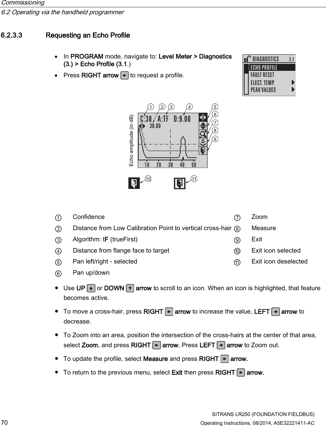
![Remote operation 7.1 Operating via AMS Device Manager SITRANS LR250 (FOUNDATION FIELDBUS) Operating Instructions, 08/2014, A5E32221411-AC 103 Echo Profile Displays the current echo profile. Navigate to Configure/Setup > LTB > Setup > Signal Processing and click on Echo Profile to view the current echo profile and to access: Echo Profile Parameters [see Echo Profile (3.1.)] ● Level Measurement [see Measured Values (2.8)] ● Distance Measurement [see Measured Values (2.8.)] ● Confidence [see Confidence (2.5.9.1.)] ● Near Range (see (Near Range 2.5.1.)] To view a previous profile, click the drop-down arrow on the Time field and select the desired profile (note: available only using AMS version 10.1or later).](https://usermanual.wiki/Siemens-Canada-Siemens-Milltronics-Process-Instruments/LR250.User-Manual-3/User-Guide-2277918-Page-103.png)
![Remote operation 7.1 Operating via AMS Device Manager SITRANS LR250 (FOUNDATION FIELDBUS) 104 Operating Instructions, 08/2014, A5E32221411-AC 7.1.9.6 Maintenance & Diagnostics (LTB) Note For more detailed explanations of the parameters listed below see the pages referenced. Navigate to Configure/Setup > LTB > Maintenance and Diagnostics for access to: Remaining Sensor Lifetime [see Remaining Sensor LIfetime (4.3.)] ● Lifetime (expected) [see Lifetime (expected) (4.3.1.)] ● Time in Operation [see Time in Operation (4.3.2.)] ● Remaining Lifetime [see Remaining Lifetime (4.3.3.)] ● Activation of Reminders [see Activation of Reminders (4.3.4.)] ● Reminder 1 before Lifetime (Required) [see Reminder 1 before Lifetime (Required) (4.3.5.)] ● Reminder 2 before Lifetime (Demanded) [see Reminder 2 before Lifetime (Demanded) (4.3.6.)] 1. Open the window Remaining Sensor Lifetime 2. After modifying values/units as required, click on Apply to accept the change. ● Click on Sensor Replaced to reset Time in Operation to 0 hours ● Click on Snooze for 1 Year to add a year to the Total Expected Sensor Life](https://usermanual.wiki/Siemens-Canada-Siemens-Milltronics-Process-Instruments/LR250.User-Manual-3/User-Guide-2277918-Page-104.png)
![Remote operation 7.1 Operating via AMS Device Manager SITRANS LR250 (FOUNDATION FIELDBUS) Operating Instructions, 08/2014, A5E32221411-AC 105 Service Schedule [see Service Schedule (4.4.)] ● Service Interval [see Service Interval (4.4.1.)] ● Time Since Last Service [see Time Since Last Service (4.4.2.)] ● Time Until Next Service [see Time Until Next Service (4.4.3.)] ● Activation of Reminders [see Activation of Reminders (4.4.4.)] ● Reminder 1 before Lifetime (Required) [see Reminder 1 before Service (Required) (4.4.5.)] ● Reminder 2 before Lifetime (Demanded) [see Reminder 2 before Service (Demanded) (4.4.6.)] ● Click on Service Performed to reset Time Since Last Service to 0 hours](https://usermanual.wiki/Siemens-Canada-Siemens-Milltronics-Process-Instruments/LR250.User-Manual-3/User-Guide-2277918-Page-105.png)
![Remote operation 7.1 Operating via AMS Device Manager SITRANS LR250 (FOUNDATION FIELDBUS) 106 Operating Instructions, 08/2014, A5E32221411-AC Electronics Temperature [see Electronics Temperature (3.3.)] ● Electronics Temperature: Displays the current internal temperature of the device ● Minimum Value [see Minimum Value (3.3.1.)] ● Maximum Value [see Maximum Value (3.3.2.)]](https://usermanual.wiki/Siemens-Canada-Siemens-Milltronics-Process-Instruments/LR250.User-Manual-3/User-Guide-2277918-Page-106.png)
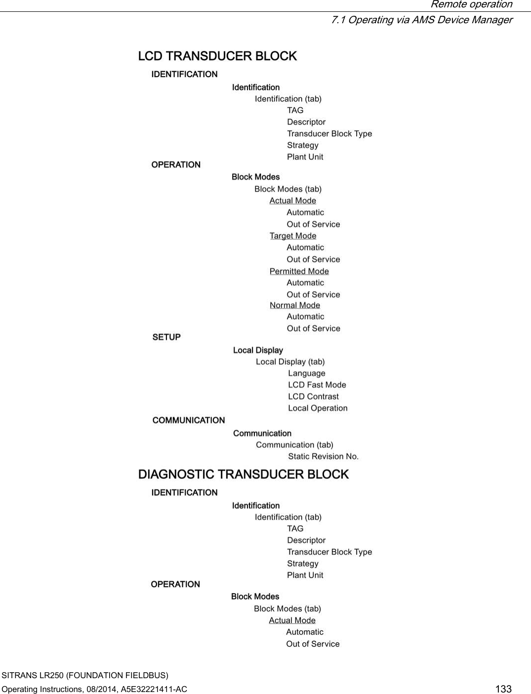
![Remote operation 7.1 Operating via AMS Device Manager SITRANS LR250 (FOUNDATION FIELDBUS) Operating Instructions, 08/2014, A5E32221411-AC 107 7.1.9.7 Communication (LTB) Navigate to Configure/Setup > LTB > Communication for access to: Communication: ● Static Revision No. [see Static Revision Number (2.6.1.)] 7.1.10 Configure/Setup (Liquid Crystal Display Block-LCD) 7.1.10.1 Identification (LCD) Navigate to Configure/Setup > LCD > Identification. Identification: ● TAG ● Descriptor ● Transducer Block Type ● Strategy ● Plant Unit Note For descriptions of Identification parameters see Identification (LTB) (Page 92).](https://usermanual.wiki/Siemens-Canada-Siemens-Milltronics-Process-Instruments/LR250.User-Manual-3/User-Guide-2277918-Page-107.png)
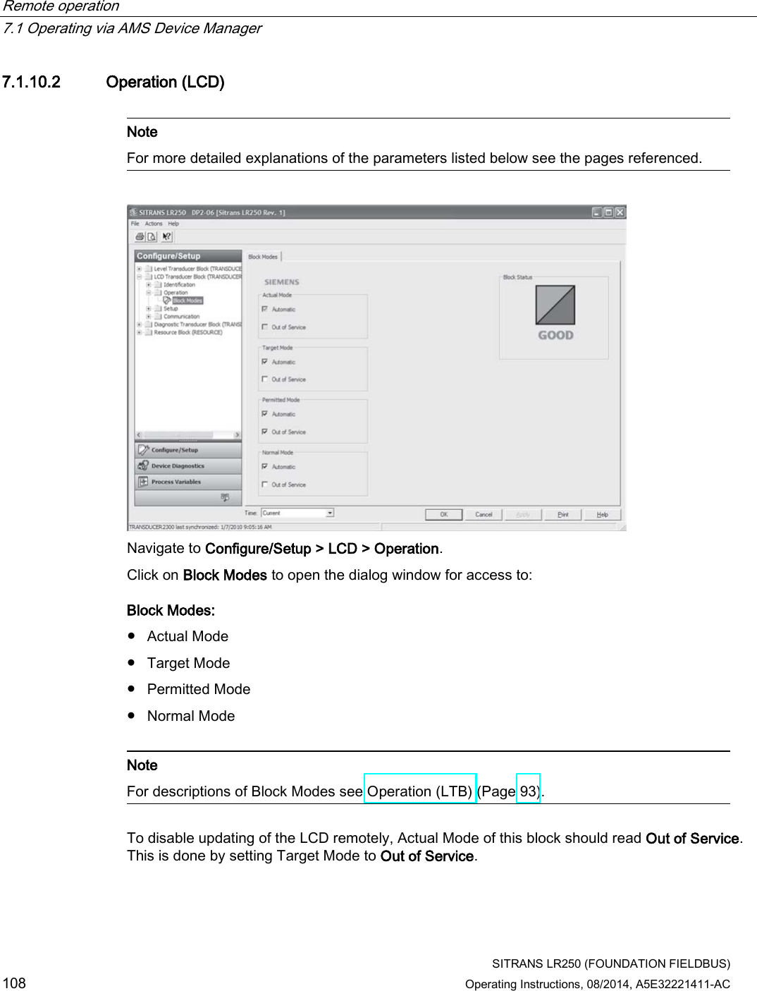
![Remote operation 7.1 Operating via AMS Device Manager SITRANS LR250 (FOUNDATION FIELDBUS) Operating Instructions, 08/2014, A5E32221411-AC 109 7.1.10.3 Setup (LCD) Navigate to Configure/Setup > LCD > Setup > Local display for access to: Local Display Language [see Language (7.)] LCD Fast Mode [see LCD Fast Mode (4.9.)] LCD Contrast [see LCD Contrast (4.10.)] Local Operation [see Local Operation (6.2.3.)] If local operation is disabled remotely and no communication activity exists for 30 seconds, the parameter is made visible again locally. 7.1.10.4 Communication (LCD) Navigate to Configure/Setup > LCD > Communication for access to: Communication: ● Static Revision No. [See Static Revision Number (2.6.1.)]](https://usermanual.wiki/Siemens-Canada-Siemens-Milltronics-Process-Instruments/LR250.User-Manual-3/User-Guide-2277918-Page-109.png)
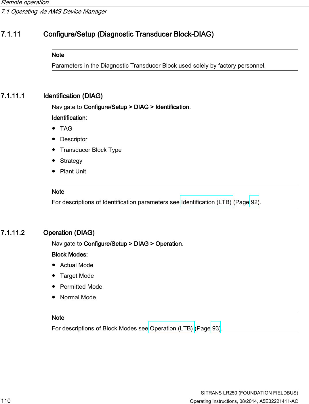
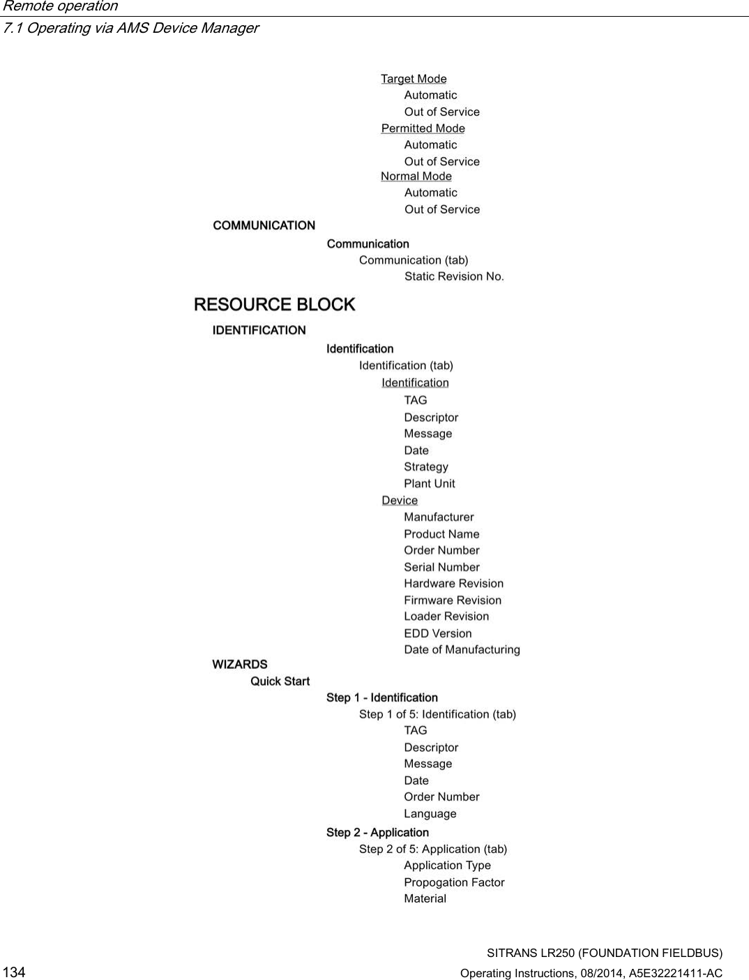
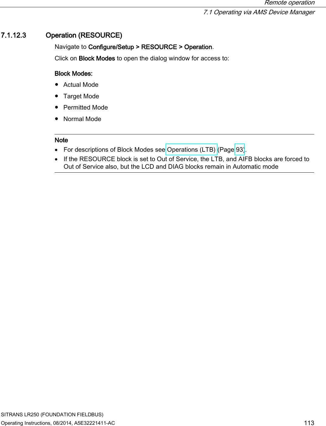
![Remote operation 7.1 Operating via AMS Device Manager SITRANS LR250 (FOUNDATION FIELDBUS) Operating Instructions, 08/2014, A5E32221411-AC 111 7.1.11.3 Communication (DIAG) Navigate to Configure/Setup > DIAG > Communication. Communication: ● Static Revision No. [see Static Revision Number (2.6.1.)] 7.1.12 Configure/Setup (Resource Block - RESOURCE) Note For more detailed explanations of the parameters listed below see the pages referenced. 7.1.12.1 Identification (RESOURCE) Navigate to Configure/Setup > RESOURCE > Identification for access to: Identification ● TAG: Read only. Description for the associated block: device tag prefixed by block type. ● Descriptor [see Descriptor (2.1.2.)] ● Message [see Message (2.1.3.)] ● Date (Installation Date): The user entered date on which the device was installed in the system. ● Strategy: Used to identify grouping of blocks. ● Plant Unit: The identification number of the plant unit. For example, can be used in the host for sorting alarms.](https://usermanual.wiki/Siemens-Canada-Siemens-Milltronics-Process-Instruments/LR250.User-Manual-3/User-Guide-2277918-Page-111.png)
![Remote operation 7.1 Operating via AMS Device Manager SITRANS LR250 (FOUNDATION FIELDBUS) 112 Operating Instructions, 08/2014, A5E32221411-AC Device (read only) ● Manufacturer (see Manufacturer (5.3.)] ● Product Name: The manufacturer’s product name for this device. ● Order Number: The manufacturer’s order number (MLFB) for this device. ● Serial Number: The manufacturer’s unique serial number for this device. ● Hardware Revision [see Hardware Revision (2.2.1.)] ● Firmware Revision [see Firmware Revision (2.2.2.)] ● Loader Revision [see Loader Revision (2.2.3.)] ● EDD Version: The version of the EDD currently installed. ● Date of Manufacturing [see Manufacture Date (4.6.)] 7.1.12.2 Wizards (RESOURCE) Navigate to Configure/Setup > RESOURCE > Wizards > Quick Start for access to Quick Start steps [see Quick Start Wizard via AMS Device Manager (Page 85)].](https://usermanual.wiki/Siemens-Canada-Siemens-Milltronics-Process-Instruments/LR250.User-Manual-3/User-Guide-2277918-Page-112.png)
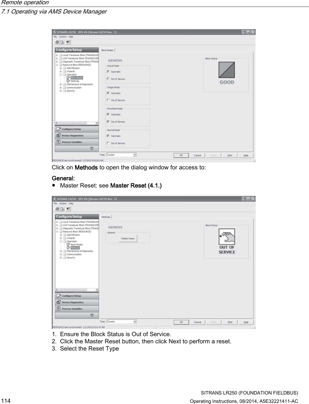
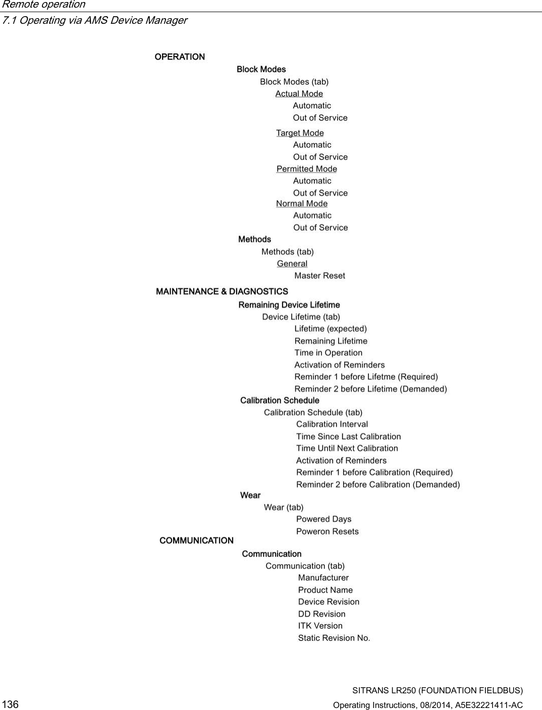
![Remote operation 7.1 Operating via AMS Device Manager SITRANS LR250 (FOUNDATION FIELDBUS) 116 Operating Instructions, 08/2014, A5E32221411-AC 7.1.12.4 Maintenance & Diagnostics (RESOURCE) Navigate to Configure/Setup > RESOURCE > Maintenance & Diagnostics for access to: Remaining Device Lifetime [see Remaining Device Lifetime (4.2.)] ● Lifetime (expected) [see Lifetime (expected (4.2.1.)] ● Remaining Lifetime (read only) [see Remaining Lifetime (4.2.3.)] ● Time in Operation (read only) [see Time in Operation (4.2.2.)] ● Activation of Reminders [see Activation of Reminders (4.2.4.)] ● Reminder 1 before Lifetime (Required) [see Reminder 1 before Lifetime (Required) (4.2.5.)] ● Reminder 2 before Lifetime (Demanded) [see Reminder 2 before Lifetime (Demanded) (4.2.6.)] 1. Open the window Remaining Device Lifetime 2. After modifying values/units as required, click on Apply to accept the change. ● Click on Snooze for 1 Year to add a year to the Total Expected Device Life.](https://usermanual.wiki/Siemens-Canada-Siemens-Milltronics-Process-Instruments/LR250.User-Manual-3/User-Guide-2277918-Page-116.png)
![Remote operation 7.1 Operating via AMS Device Manager SITRANS LR250 (FOUNDATION FIELDBUS) Operating Instructions, 08/2014, A5E32221411-AC 117 Calibration Schedule [see Calibration Schedule (4.5)] ● Calibration Interval [see Calibration Interval (4.5.1.)] ● Time Since Last Calibration [see Time Since Last Calibration (4.5.2.)] ● Time Until Next Calibration (read only) [see Time Until Next Calibration (4.5.3.)] ● Activation of Reminders [see Activation of Reminders (4.5.4.)] ● Reminder 1 before Calibration (Required) [see Reminder 1 before Calibration (Required) (4.5.5.)] ● Reminder 2 before Calibration (Demanded) [see Reminder 2 before Calibration (Demanded) (4.5.6.)] ● Click on Calibration Performed to reset Time Since Last Calibration to 0 hours.](https://usermanual.wiki/Siemens-Canada-Siemens-Milltronics-Process-Instruments/LR250.User-Manual-3/User-Guide-2277918-Page-117.png)
![Remote operation 7.1 Operating via AMS Device Manager SITRANS LR250 (FOUNDATION FIELDBUS) 118 Operating Instructions, 08/2014, A5E32221411-AC Wear ● Powered Days (read only) [see Powered Hours (4.7.)] ● Poweron Resets (read only) [see Power-on Resets (4.8.)] 7.1.12.5 Communication (RESOURCE) ● Navigate to Configure/Setup > RESOURCE > Communication to read the following: ● Manufacturer [see Manufacturer (5.3.)] ● Product Name: the manufacturer’s product name for this device. ● Device Revision [see Device Revision (5.5.)] ● DD Revision: revision of the DD (also called EDD) associated with this device. ● ITK Version [see ITK Version (5.6.)] ● Static Revision No. [see Static Revision Number ( 2.6.1.)]](https://usermanual.wiki/Siemens-Canada-Siemens-Milltronics-Process-Instruments/LR250.User-Manual-3/User-Guide-2277918-Page-118.png)
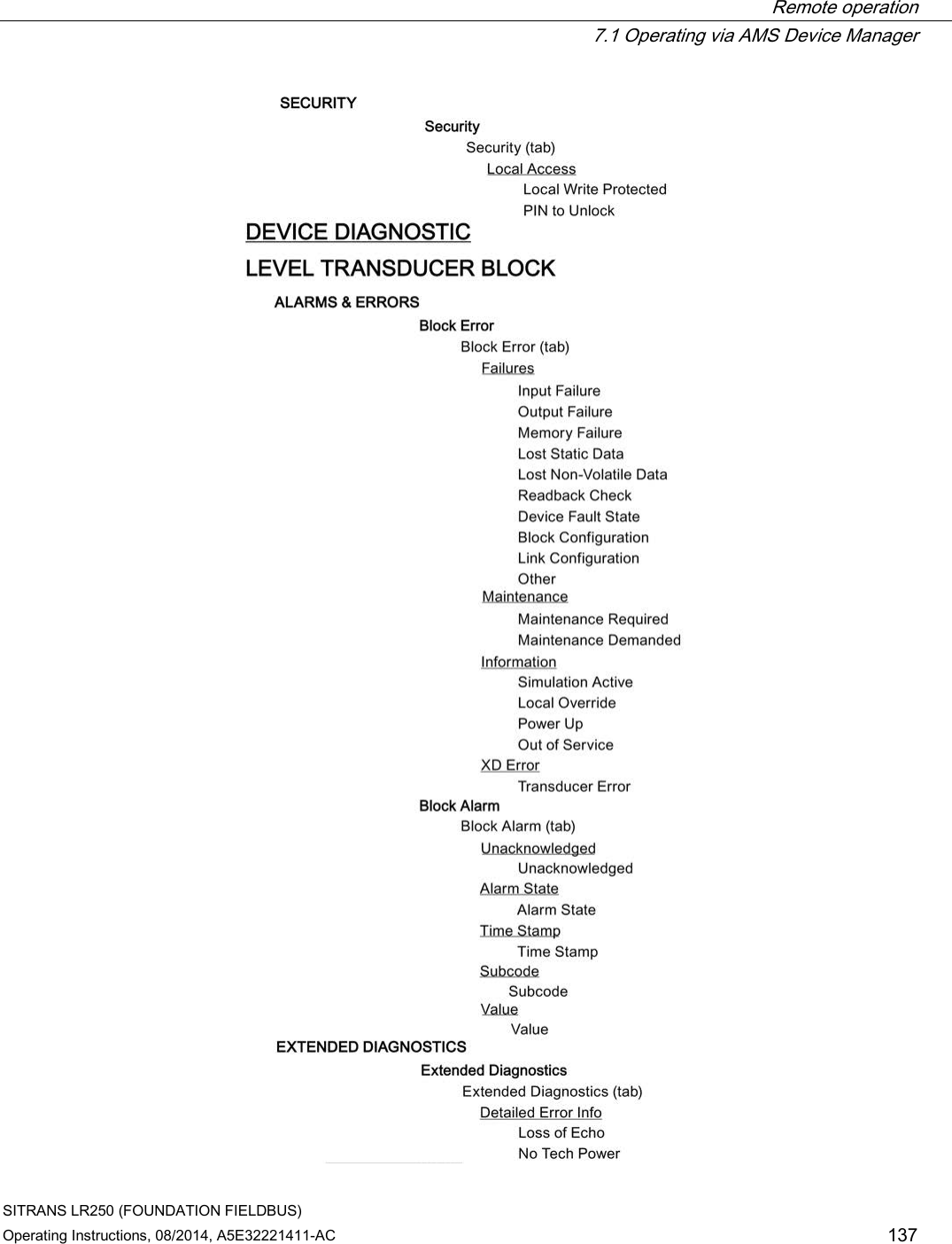
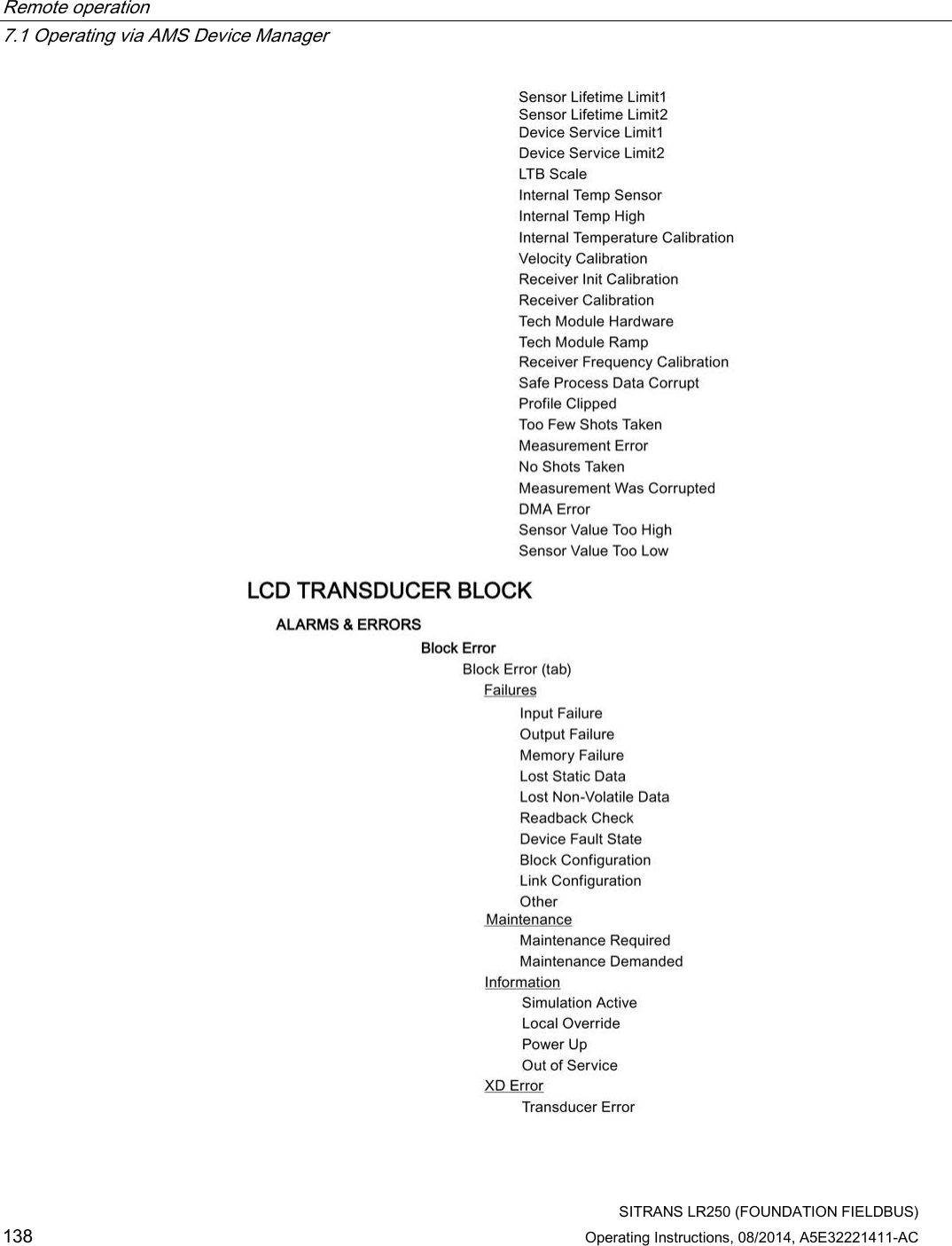
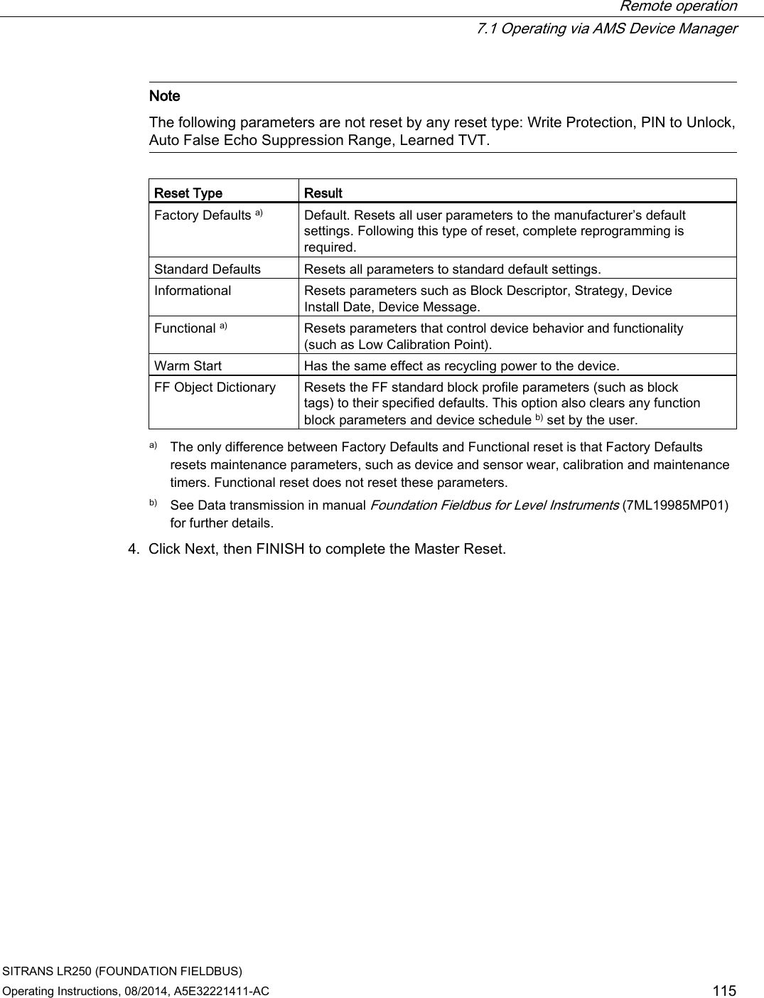
![Remote operation 7.1 Operating via AMS Device Manager SITRANS LR250 (FOUNDATION FIELDBUS) Operating Instructions, 08/2014, A5E32221411-AC 119 7.1.12.6 Security (RESOURCE) Navigate to Configure/Setup > RESOURCE > Security to access: Local Access ● Local Write Protected [see Write Protection (6.2.1.)] ● PIN to Unlock [see PIN to Unlock (6.2.2.)] See also Password Protection (Page 129). 7.1.13 Device Diagnostics (Level Transducer Block - LTB) Note For explanations of the alarms and errors listed below, see Parameter Description charts for the respective block in manual Foundation Fieldbus for Level Instruments (7ML19985MP01).](https://usermanual.wiki/Siemens-Canada-Siemens-Milltronics-Process-Instruments/LR250.User-Manual-3/User-Guide-2277918-Page-119.png)
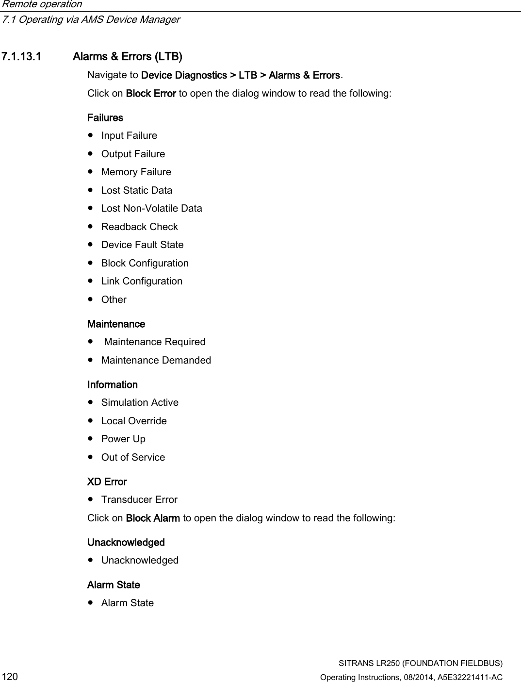
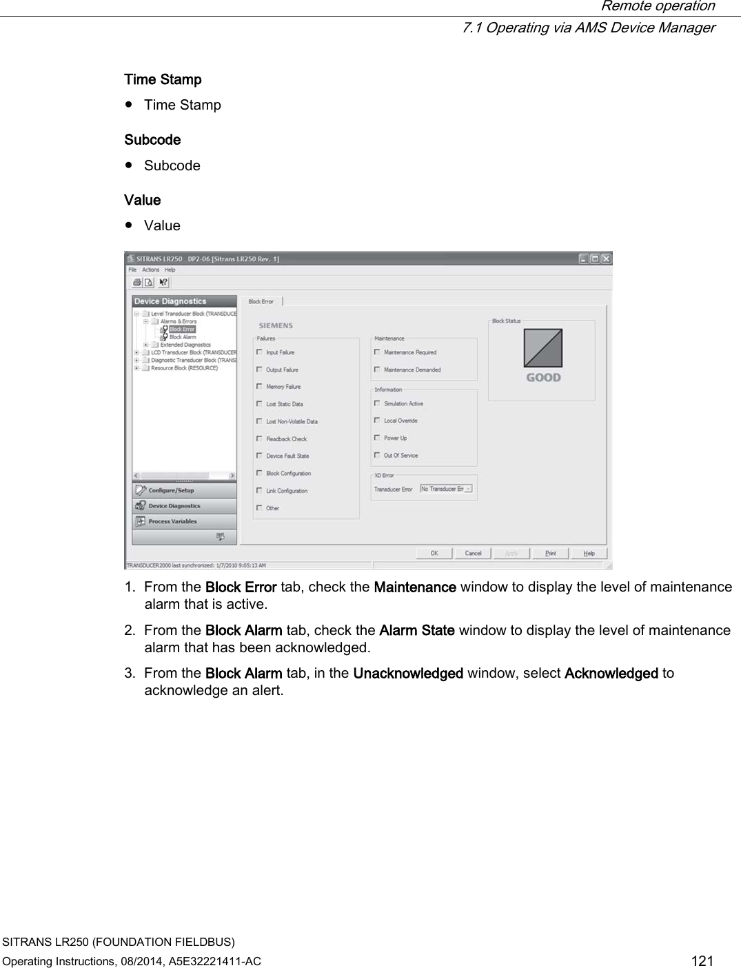
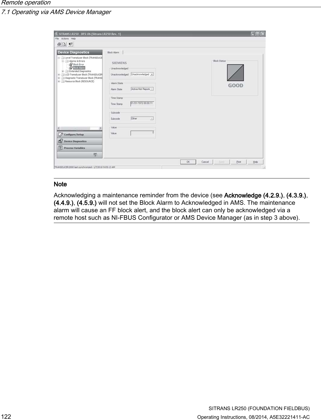
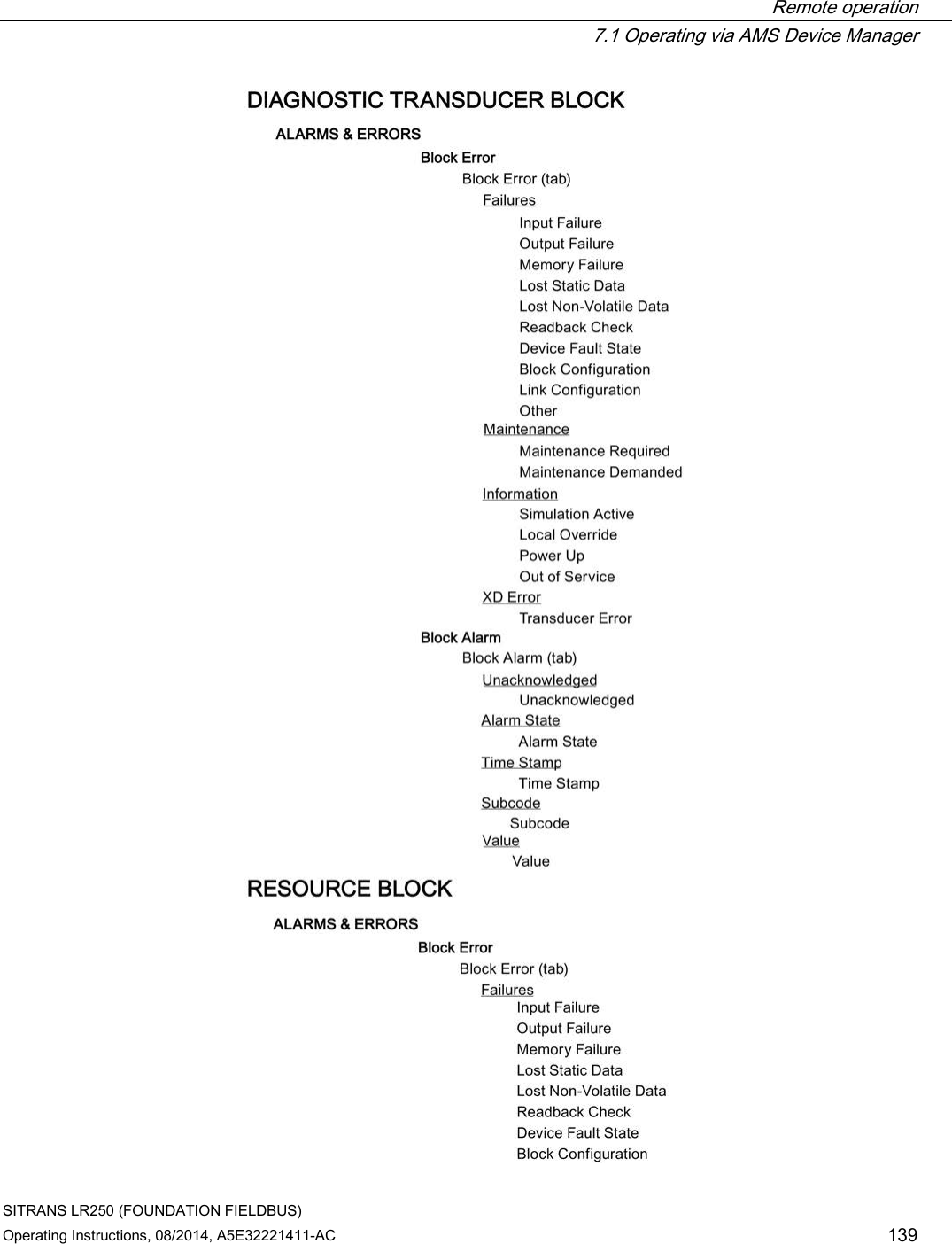
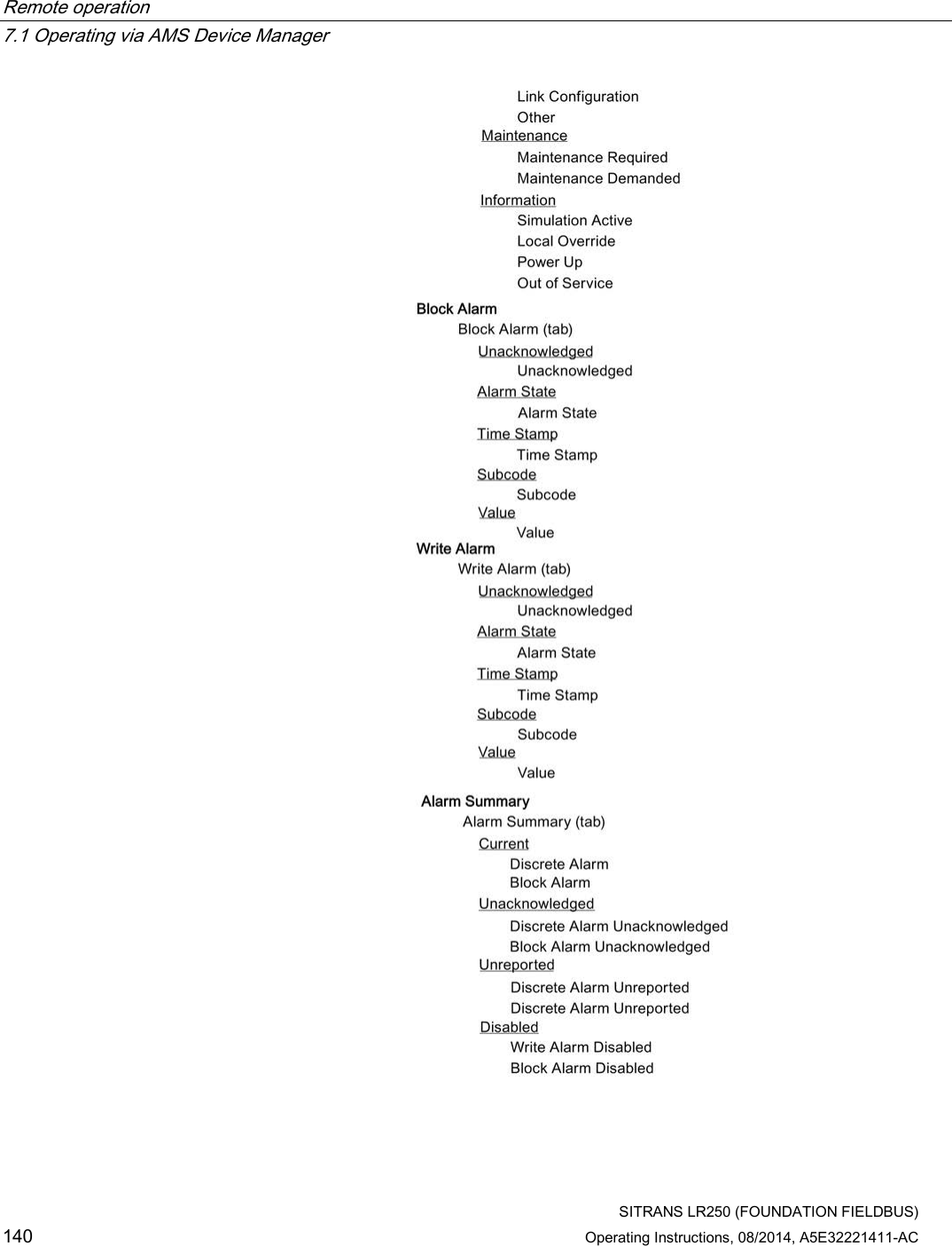
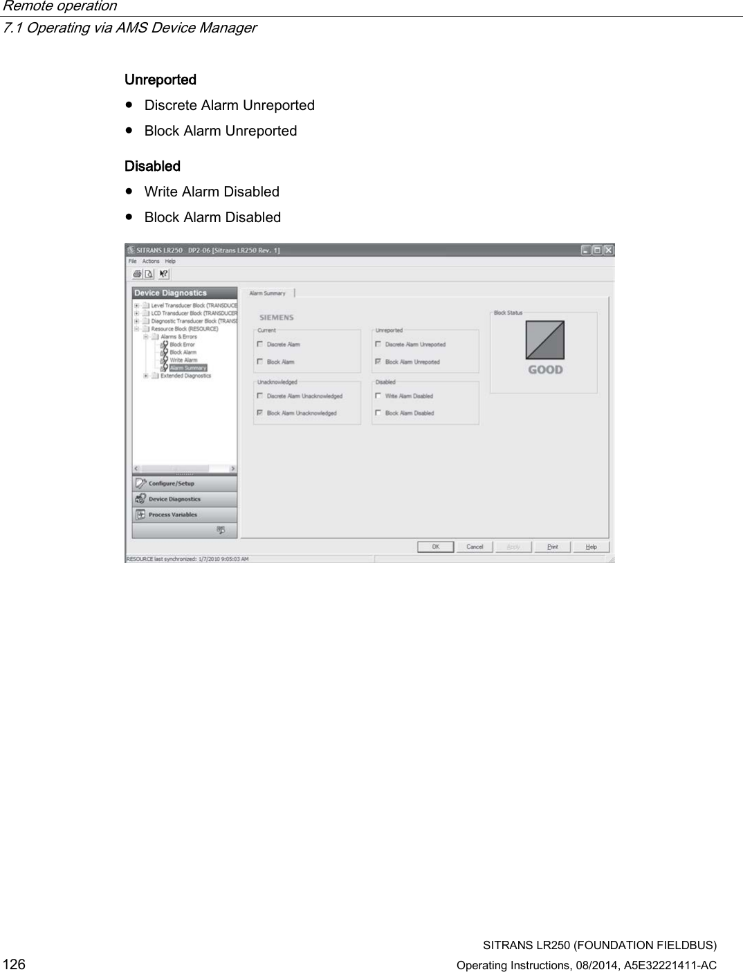
![Remote operation 7.1 Operating via AMS Device Manager SITRANS LR250 (FOUNDATION FIELDBUS) 124 Operating Instructions, 08/2014, A5E32221411-AC 7.1.14 Device Diagnostics (Liquid Crystal Display Block - LCD) 7.1.14.1 Alarms & Errors (LCD) Navigate to Device Diagnostics > LCD > Alarms & Errors to read Block and Alarm errors. [Errors displayed are the same for each block (LTB, LCD, DIAG, RESOURCE). See Alarms & Errors (LTB) (Page 120) for full listing.] 7.1.15 Device Diagnostics (Diagnostic Transducer Block - DIAG) 7.1.15.1 Alarms & Errors (DIAG) Navigate to Device Diagnostics > DIAG > Alarms & Errors to read Block and Alarm errors. [Errors displayed are the same for each block (LTB, LCD, DIAG, RESOURCE). See Alarms & Errors (LTB) (Page 120) for full listing. See AMS Device Manager instruction manual to work with alarms and errors.] 7.1.16 Device Diagnostics (Resource Block - RESOURCE) 7.1.16.1 Alarms & Errors (RESOURCE) Navigate to Device Diagnostics > RESOURCE > Alarms & Errors. Click on Block Error tab to open the dialog window to read the following: Failures ● Input Failure ● Output Failure ● Memory Failure ● Lost Static Data ● Lost Non-Volatile Data ● Readback Check ● Device Fault State ● Block Configuration ● Link Configuration ● Other](https://usermanual.wiki/Siemens-Canada-Siemens-Milltronics-Process-Instruments/LR250.User-Manual-3/User-Guide-2277918-Page-124.png)
![Remote operation 7.1 Operating via AMS Device Manager SITRANS LR250 (FOUNDATION FIELDBUS) 128 Operating Instructions, 08/2014, A5E32221411-AC 7.1.17 Process Variables (Level Transducer Block - LTB) To compare outputs in real time navigate to Process Variables > LTB. Click on Process Variables then the Values tab to read the following: Primary Variable [see Main Output (PV - Primary Value) (2.8.1.)] ● Level/Volume (PV) The primary variable and the channel 1 output from the transducer block. For level applications, chart range is affected by High and Low Level Point values set in Configure/Setup > LTB > Setup > Sensor. For volume applications, chart range is 0 to Max. Volume, set in Configure/Setup > LTB > Setup > Linearization. Click on Trend View tab to read the following: Trend Values ● Level/Volume (PV) The primary variable and the channel 1 output from the transducer block. Click on Echo Profile to open the dialog window to read the following: Echo Profile • Level Measurement [see Measured Values (2.8.)] • Distance Measurement [see Measured Values (2.8.)] • Confidence [see Confidence (2.5.9.1.)] • Near Range [see Near Range (2.5.1.)]](https://usermanual.wiki/Siemens-Canada-Siemens-Milltronics-Process-Instruments/LR250.User-Manual-3/User-Guide-2277918-Page-128.png)