Siemens Canada Siemens Milltronics Process Instruments LR250 SITRANS LR 250 TANK LEVEL PROBING RADAR User Manual SITRANS LR250 mA HART
Siemens Canada Ltd. - Siemens Milltronics Process Instruments SITRANS LR 250 TANK LEVEL PROBING RADAR SITRANS LR250 mA HART
Contents
User Manual 1
SITRANS
Radar Transmitters
SITRANS LR250 (mA/HART)
Operating Instructions 08/2014

© Siemens AG 2013
Safety Guidelines
Warning notices must be observed to ensure personal safety as well as that of others, and to protect the product and the connected equipment.
These warning notices are accompanied by a clarification of the level of caution to be observed.
Qualified Personnel
This device/system may only be set up and operated in conjunction with this manual. Qualified personnel are only authorized to install and
operate this equipment in accordance with established safety practices and standards.
Unit Repair and Excluded Liability:
The user is responsible for all changes and repairs made to the device by the user or the user’s agent.
All new components are to be provided by Siemens Milltronics Process Instruments.
Restrict repair to faulty components only.
Do not reuse faulty components.
Warning: Cardboard shipping package provides limited humidity and moisture protection. This product can only function properly and safely if
it is correctly transported, stored, installed, set up, operated, and maintained.
This product is intended for use in industrial areas. Operation of this equipment in a residential area may cause interference to several
frequency based communications.
Note: Always use product in accordance with specifications.
Copyright Siemens AG 2013. All Rights Reserved Disclaimer of Liability
This document is available in bound version and in
electronic version. We encourage users to purchase
authorized bound manuals, or to view electronic versions as
designed and authored by Siemens Milltronics Process
Instruments. Siemens Milltronics Process Instruments will
not be responsible for the contents of partial or whole
reproductions of either bound or electronic versions.
While we have verified the contents of this
manual for agreement with the instrumentation
described, variations remain possible. Thus we
cannot guarantee full agreement. The contents of
this manual are regularly reviewed and
corrections are included in subsequent editions.
We welcome all suggestions for improvement.
Technical data subject to change.
MILLTRONICS®is a registered trademark of Siemens Milltronics Process Instruments.
Contact SMPI Technical Publications European Authorized Representative
at the following address:
Technical Publications Siemens AG
Siemens AG Industry Sector
Siemens Milltronics Process Instruments 76181 Karlsruhe
1954 Technology Drive, P.O. Box 4225 Deutschland
Peterborough, Ontario, Canada, K9J 7B1
Email: techpubs.smpi@siemens.com
For a selection of Siemens Milltronics level measurement manuals, go to:
www. siemens.com/processautomation. Under Process Instrumentation, select
Level Measurement
and then go to the manual archive
listed under the product family.
For a selection of Siemens Milltronics weighing manuals, go to:
www. siemens.com/processautomation. Under Weighing Technology, select
Continuous Weighing Systems
and then go to the manual
archive listed under the product family.

SITRANS LR250 (mA/HART)
___________________
___________________
___________________
___________________
___________________
___________________
___________________
___________________
___________________
___________________
___________________
___________________
___________________
___________________
___________________
___________________
___________________
SITRANS
Radar Transmitters
SITRANS LR250 (mA/HART)
Operating Instructions
08/2014
A5E32220602
-AC
Introduction
1
Safety information
2
Description
3
Installing/mounting
4
Connecting
5
Commissioning
6
Remote operation
7
Parameter reference
8
Service and maintenance
9
Diagnosing and
troubleshooting
10
Technical data
11
Dimension drawings
12
Appendix A: Technical
reference
A
Appendix B: HART
communications
B
Appendix C: Certificates and
support
C
List of abbreviations
13
LCD menu structure
14
Siemens AG
Industry Sector
Postfach 48 48
90026 NÜRNBERG
GERMANY
Order number: A5E32220602
Ⓟ
03/2014 Subject to change
Copyright © Siemens AG 2014.
All rights reserved
Legal information
Warning notice system
This manual contains notices you have to observe in order to ensure your personal safety, as well as to prevent
damage to property. The notices referring to your personal safety are highlighted in the manual by a safety alert
symbol, notices referring only to property damage have no safety alert symbol. These notices shown below are
graded according to the degree of danger.
DANGER
indicates that death or severe personal injury will result if proper precautions are not taken.
WARNING
indicates that death or severe personal injury may result if proper precautions are not taken.
CAUTION
indicates that minor personal injury can result if proper precautions are not taken.
NOTICE
indicates that property damage can result if proper precautions are not taken.
If more than one degree of danger is present, the warning notice representing the highest degree of danger will be
used. A notice warning of injury to persons with a safety alert symbol may also include a warning relating to property
damage.
Qualified Personnel
The product/system described in this documentation may be operated only by
personnel qualified
for the specific task
in accordance with the relevant documentation, in particular its warning notices and safety instructions. Qualified
personnel are those who, based on their training and experience, are capable of identifying risks and avoiding
potential hazards when working with these products/systems.
Proper use of Siemens products
Note the following:
WARNING
Siemens products may only be used for the applications described in the catalog and in the relevant technical
documentation. If products and components from other manufacturers are used, these must be recommended
or approved by Siemens. Proper transport, storage, installation, assembly, commissioning, operation and
maintenance are required to ensure that the products operate safely and without any problems. The permissible
ambient conditions must be complied with. The information in the relevant documentation must be observed.
Trademarks
All names identified by ® are registered trademarks of Siemens AG. The remaining trademarks in this publication may
be trademarks whose use by third parties for their own purposes could violate the rights of the owner.
Disclaimer of Liability
We have reviewed the contents of this publication to ensure consistency with the hardware and software described.
Since variance cannot be precluded entirely, we cannot guarantee full consistency. However, the information in this
publication is reviewed regularly and any necessary corrections are included in subsequent editions.
SITRANS LR250 (mA/HART)
Operating Instructions, 08/2014, A5E32220602-AC 3
Table of contents
1 Introduction ............................................................................................................................................. 9
1.1 LR250 mA/HART manual usage.................................................................................................... 9
1.2 Purpose of this documentation ...................................................................................................... 9
1.3 Document history ........................................................................................................................... 9
1.4 Firmware revision history ............................................................................................................. 10
1.5 Designated use ............................................................................................................................ 11
1.6 Checking the consignment ........................................................................................................... 11
1.7 Transportation and storage .......................................................................................................... 12
1.8 Notes on warranty ........................................................................................................................ 12
2 Safety information ................................................................................................................................. 13
2.1 Preconditions for safe use ........................................................................................................... 13
2.1.1 Safety marking symbols ............................................................................................................... 13
2.1.2 Laws and directives ..................................................................................................................... 13
2.1.3 FCC Conformity ........................................................................................................................... 14
2.1.4 Conformity with European directives ........................................................................................... 15
2.1.5 CE Electromagnetic Compatibility (EMC) Conformity.................................................................. 16
2.2 Improper device modifications ..................................................................................................... 16
2.3 Requirements for special applications ......................................................................................... 17
2.4 Use in hazardous areas ............................................................................................................... 17
3 Description ............................................................................................................................................ 19
3.1 SITRANS LR250 overview ........................................................................................................... 19
3.2 Programming ................................................................................................................................ 20
3.3 Applications .................................................................................................................................. 20
3.4 Approvals and certificates ............................................................................................................ 20
4 Installing/mounting ................................................................................................................................ 21
4.1 Basic safety information ............................................................................................................... 21
4.1.1 Pressure applications ................................................................................................................... 22
4.1.1.1 Pressure Equipment Directive, PED, 97/23/EC ........................................................................... 23
4.2 Installation location requirements ................................................................................................ 24
4.3 Proper mounting........................................................................................................................... 26
4.3.1 Nozzle design ............................................................................................................................... 27

Table of contents
SITRANS LR250 (mA/HART)
4 Operating Instructions, 08/2014, A5E32220602-AC
4.3.2 Nozzle location ............................................................................................................................ 28
4.3.3 Orientation in a vessel with obstructions ..................................................................................... 31
4.3.4 Mounting on a Stillpipe or Bypass Pipe ...................................................................................... 32
4.3.5 Device orientation ....................................................................................................................... 33
4.4 Installation instructions ................................................................................................................ 34
4.4.1 Threaded versions ...................................................................................................................... 35
4.4.2 Flanged versions ......................................................................................................................... 35
4.4.3 Hygienic versions ........................................................................................................................ 38
4.5 Disassembly ................................................................................................................................ 39
5 Connecting ........................................................................................................................................... 41
5.1 Basic safety information .............................................................................................................. 41
5.2 Connecting SITRANS LR250 ...................................................................................................... 41
5.3 Wiring setups for hazardous area installations ........................................................................... 45
5.3.1 Intrinsically safe wiring ................................................................................................................ 45
5.3.2 Non-sparking wiring .................................................................................................................... 47
5.3.3 Non-incendive wiring (US/Canada only) ..................................................................................... 47
5.3.4 Flameproof wiring ........................................................................................................................ 48
5.3.5 Increased safety wiring ............................................................................................................... 49
5.3.6 Explosion-proof wiring (US/Canada only) ................................................................................... 49
5.4 Instructions specific to hazardous area installations ................................................................... 50
5.4.1 (Reference European ATEX Directive 94/9/EC, Annex II, 1/0/6)................................................ 50
6 Commissioning ..................................................................................................................................... 53
6.1 Basic safety information .............................................................................................................. 53
6.2 Operating via the handheld programmer .................................................................................... 53
6.2.1 Power up ..................................................................................................................................... 54
6.2.2 Handheld programmer functions ................................................................................................. 54
6.2.2.1 The LCD display .......................................................................................................................... 55
6.2.2.2 Handheld programmer (Part No. 7ML1930-1BK) ....................................................................... 57
6.2.3 Programming ............................................................................................................................... 59
6.2.3.1 Quick Start Wizard via the handheld programmer ...................................................................... 64
6.2.3.2 Auto False Echo Suppression ..................................................................................................... 68
6.2.3.3 Requesting an Echo Profile......................................................................................................... 69
6.3 Application examples .................................................................................................................. 70
6.3.1 Liquid resin in storage vessel, level measurement ..................................................................... 71
6.3.2 Horizontal vessel with volume measurement .............................................................................. 72
6.3.3 Application with stillpipe .............................................................................................................. 74
7 Remote operation ................................................................................................................................. 77
7.1 Operating via SIMATIC PDM ...................................................................................................... 77
7.1.1 Functions in SIMATIC PDM ........................................................................................................ 77
7.1.1.1 PDM function overview ............................................................................................................... 77
7.1.1.2 Features of SIMATIC PDM Rev. 6.0, SP4 or higher ................................................................... 78

Table of contents
SITRANS LR250 (mA/HART)
Operating Instructions, 08/2014, A5E32220602-AC 5
7.1.1.3 Features of SIMATIC PDM Rev. 5.2, SP1 ................................................................................... 78
7.1.1.4 SIMATIC PDM Version ................................................................................................................ 78
7.1.2 Initial setup ................................................................................................................................... 78
7.1.2.1 Deactivating buffers ..................................................................................................................... 79
7.1.3 Updating the Electronic Device Description (EDD) ...................................................................... 80
7.1.3.1 Configuring a new device ............................................................................................................. 80
7.1.4 Quick Start Wizard via SIMATIC PDM ......................................................................................... 81
7.1.5 Changing parameter settings using SIMATIC PDM .................................................................... 86
7.1.6 Parameters accessed via pull-down menus ................................................................................ 87
7.1.6.1 Echo profile utilities ...................................................................................................................... 88
7.1.6.2 Echo profile .................................................................................................................................. 89
7.1.6.3 View saved echo profiles ............................................................................................................. 90
7.1.6.4 TVT Shaper .................................................................................................................................. 91
7.1.6.5 Auto false echo suppression ........................................................................................................ 92
7.1.6.6 Echo setup ................................................................................................................................... 95
7.1.6.7 Maintenance ................................................................................................................................. 95
7.1.6.8 Select analog output .................................................................................................................... 97
7.1.6.9 Self test ........................................................................................................................................ 97
7.1.6.10 Loop test ...................................................................................................................................... 97
7.1.6.11 Configuration flag reset ................................................................................................................ 97
7.1.6.12 Master reset ................................................................................................................................. 98
7.1.6.13 Wear ............................................................................................................................................. 98
7.1.6.14 HART Communication ................................................................................................................. 98
7.1.6.15 Process variables ......................................................................................................................... 99
7.1.6.16 Trend .......................................................................................................................................... 100
7.1.6.17 Device status .............................................................................................................................. 101
7.1.6.18 Update ........................................................................................................................................ 101
7.1.6.19 Security ...................................................................................................................................... 102
7.2 Operating via AMS Device Manager.......................................................................................... 103
7.2.1 Functions in AMS Device Manager............................................................................................ 103
7.2.1.1 AMS function overview .............................................................................................................. 103
7.2.1.2 Features of AMS Device Manager ............................................................................................. 104
7.2.1.3 Electronic Device Description (EDD) ......................................................................................... 104
7.2.1.4 Configuring a new device ........................................................................................................... 104
7.2.1.5 Startup ........................................................................................................................................ 105
7.2.1.6 Pull-down menu access ............................................................................................................. 106
7.2.1.7 Device configuration .................................................................................................................. 107
7.2.1.8 Quick Start Wizard via AMS Device Manager ........................................................................... 107
7.2.2 Maintenance and diagnostics .................................................................................................... 116
7.2.3 Communication .......................................................................................................................... 117
7.2.4 Security ...................................................................................................................................... 118
7.2.5 Device Diagnostics .................................................................................................................... 119
7.2.5.1 Process variables ....................................................................................................................... 120
7.2.5.2 Password protection .................................................................................................................. 121
7.2.5.3 User Manager utility ................................................................................................................... 121
7.2.6 AMS menu structure .................................................................................................................. 122
7.3 Operating via FDT (Field Device Tool) ...................................................................................... 126

Table of contents
SITRANS LR250 (mA/HART)
6 Operating Instructions, 08/2014, A5E32220602-AC
7.3.1 Device Type Manager (DTM) .................................................................................................... 126
7.3.2 SITRANS DTM .......................................................................................................................... 126
7.3.3 The device EDD ........................................................................................................................ 126
7.3.4 Configuring a new device via FDT ............................................................................................ 126
8 Parameter reference ............................................................................................................................ 127
8.1 Alphabetical parameter list ........................................................................................................ 179
9 Service and maintenance ..................................................................................................................... 183
9.1 Basic safety information ............................................................................................................ 183
9.2 Cleaning .................................................................................................................................... 183
9.3 Maintenance and repair work .................................................................................................... 184
9.3.1 Unit repair and excluded liability ............................................................................................... 185
9.3.2 Part replacement ....................................................................................................................... 185
9.4 Disposal..................................................................................................................................... 187
10 Diagnosing and troubleshooting ........................................................................................................... 189
10.1 Communication troubleshooting ............................................................................................... 189
10.2 Device status icons ................................................................................................................... 190
10.3 General fault codes ................................................................................................................... 192
10.4 Operation troubleshooting ......................................................................................................... 196
11 Technical data ..................................................................................................................................... 199
11.1 Power ........................................................................................................................................ 199
11.2 Performance .............................................................................................................................. 199
11.3 Interface .................................................................................................................................... 201
11.4 Mechanical ................................................................................................................................ 202
11.5 Environmental ........................................................................................................................... 205
11.6 Process ..................................................................................................................................... 205
11.7 Approvals .................................................................................................................................. 206
11.8 Programmer (infrared keypad) .................................................................................................. 208
12 Dimension drawings ............................................................................................................................. 209
12.1 Threaded horn antenna ............................................................................................................. 209
12.2 Threaded horn antenna with extension ..................................................................................... 212
12.3 Flanged horn antenna ............................................................................................................... 214
12.4 Flanged horn antenna with extension ....................................................................................... 216
12.5 Flanged encapsulated antenna (2"/DN50/50A sizes only) ....................................................... 218
12.6 Flanged encapsulated antenna (3"/DN80/80A sizes and larger) .............................................. 220

Table of contents
SITRANS LR250 (mA/HART)
Operating Instructions, 08/2014, A5E32220602-AC 7
12.7 Hygienic encapsulated antenna (2" ISO 2852 sanitary clamp) ................................................. 222
12.8 Hygienic encapsulated antenna (3" ISO 2852 sanitary clamp) ................................................. 223
12.9 Hygienic encapsulated antenna (4" ISO 2852 sanitary clamp) ................................................. 224
12.10 Hygienic encapsulated antenna (DN 50 nozzle/slotted nut to DIN 11851) ............................... 225
12.11 Hygienic encapsulated antenna (DN 80 nozzle/slotted nut to DIN 11851) ............................... 226
12.12 Hygienic encapsulated antenna (DN 100 nozzle/slotted nut to DIN 11851) ............................. 227
12.13 Hygienic encapsulated antenna (DN 50 aseptic clamp to DIN 11864-1) .................................. 228
12.14 Hygienic encapsulated antenna (DN 80 aseptic clamp to DIN 11864-1) .................................. 229
12.15 Hygienic encapsulated antenna (DN 100 aseptic clamp to DIN 11864-1) ................................ 230
12.16 Hygienic encapsulated antenna (DN 50 aseptic flange to DIN 11864-2) .................................. 231
12.17 Hygienic encapsulated antenna (DN 80 aseptic flange to DIN 11864-2) .................................. 232
12.18 Hygienic encapsulated antenna (DN 100 aseptic flange to DIN 11864-2) ................................ 233
12.19 Hygienic encapsulated antenna (DN 50 aseptic clamp to DIN 11864-3) .................................. 234
12.20 Hygienic encapsulated antenna (DN 80 aseptic clamp to DIN 11864-3) .................................. 235
12.21 Hygienic encapsulated antenna (DN 100 aseptic clamp to DIN 11864-3) ................................ 236
12.22 Hygienic encapsulated antenna (Tuchenhagen Type N) .......................................................... 237
12.23 Hygienic encapsulated antenna (Tuchenhagen Type F) ........................................................... 238
12.24 Threaded PVDF antenna ........................................................................................................... 239
12.25 Threaded connection markings .................................................................................................. 240
12.26 Raised-Face flange per EN 1092-1 for flanged horn antenna ................................................... 241
12.27 Raised-Face flange per EN 1092-1 for flanged encapsulated antenna..................................... 243
12.28 Flat-Face flange ......................................................................................................................... 246
12.29 Aseptic/hygienic flange DN50, DN80, DN100 for DIN 11864-2 ................................................. 249
12.30 Process connection tag (pressure rated versions) .................................................................... 252
A Appendix A: Technical reference ......................................................................................................... 253
A.1 Principles of operation ............................................................................................................... 253
A.2 Echo Processing ........................................................................................................................ 254
A.2.1 Process Intelligence ................................................................................................................... 254
A.2.2 Echo Selection ........................................................................................................................... 255
A.2.3 CLEF Range .............................................................................................................................. 258
A.2.4 Echo Threshold .......................................................................................................................... 258
A.2.5 Echo Lock .................................................................................................................................. 258
A.2.6 Auto False Echo Suppression .................................................................................................... 259
A.2.7 Measurement Range ................................................................................................................. 261
A.2.8 Measurement Response ............................................................................................................ 261

Table of contents
SITRANS LR250 (mA/HART)
8 Operating Instructions, 08/2014, A5E32220602-AC
A.2.9 Damping .................................................................................................................................... 262
A.3 Analog Output ........................................................................................................................... 262
A.3.1 Sensor Mode ............................................................................................................................. 263
A.3.2 Current Output Function ............................................................................................................ 264
A.3.3 Loss of Echo (LOE) ................................................................................................................... 264
A.3.4 Fail-safe Mode .......................................................................................................................... 265
A.4 Maximum Process Temperature Chart ..................................................................................... 265
A.5 Process Pressure/Temperature derating curves ...................................................................... 267
A.5.1 Pressure Equipment Directive, PED, 97/23/EC ........................................................................ 268
A.5.2 Horn antenna ............................................................................................................................ 269
A.5.3 Flanged horn antenna ............................................................................................................... 270
A.5.4 Flanged encapsulated antenna ................................................................................................. 275
A.5.5 PVDF antenna ........................................................................................................................... 277
A.5.6 Hygienic encapsulated antenna ................................................................................................ 278
A.6 Loop power ............................................................................................................................... 281
A.6.1 Allowable operating area of SITRANS LR250 .......................................................................... 281
A.6.2 Curve 1 (General Purpose, Intrinsically Safe, Non-Sparking, Non-incendive) ......................... 282
A.6.3 Curve 2 (Flameproof, Increased Safety, Explosion-proof) ........................................................ 283
A.7 Startup behavior ........................................................................................................................ 283
B Appendix B: HART communications ..................................................................................................... 285
B.1 SIMATIC PDM ........................................................................................................................... 285
B.2 HART Electronic Device Description (EDD) ............................................................................. 285
B.3 HART Handheld 375/475 .......................................................................................................... 285
B.4 HART Communicator 375 menu structure ................................................................................ 286
B.5 HART version ............................................................................................................................ 288
B.5.1 Burst Mode ................................................................................................................................ 288
B.5.2 HART Multidrop Mode ............................................................................................................... 288
C Appendix C: Certificates and support ................................................................................................... 289
C.1 Certificates ................................................................................................................................ 289
C.2 Technical support ...................................................................................................................... 289
13 List of abbreviations ............................................................................................................................. 291
14 LCD menu structure ............................................................................................................................. 293
14.1 LCD menu structure .................................................................................................................. 293
Glossary .............................................................................................................................................. 297
Index ................................................................................................................................................... 303

SITRANS LR250 (mA/HART)
Operating Instructions, 08/2014, A5E32220602-AC 9
Introduction
1
1.1
LR250 mA/HART manual usage
Note
This manual applies to the SITRANS LR250 mA/HART version only. HART
® is a registered
trademark of the HART Communication Foundation.
Follow these operating instructions for quick, trouble-free installation, and maximum accuracy
and reliability of your device.
We always welcome suggestions and comments about manual content, design, and
accessibility. Please direct your comments to:
Technical publications (mailto:techpubs.smpi@siemens.com)
1.2
Purpose of this documentation
These instructions contain all information required to commission and use the device. It is your
responsibility to read the instructions carefully prior to installation and commissioning. In order to
use the device correctly, first review its principle of operation.
The instructions are aimed at persons mechanically installing the device, connecting it
electronically, configuring the parameters and commissioning it, as well as service and
maintenance engineers.
1.3
Document history
The following table notes major changes in the documentation compared to the previous edition.
Edition
Remark
January 2014 • Flanged encapsulated antenna version added.
August 2014 • Hygienic encapsulated antenna version added.

Introduction
1.4 Firmware revision history
SITRANS LR250 (mA/HART)
10 Operating Instructions, 08/2014, A5E32220602-AC
1.4
Firmware revision history
This history establishes the correlation between the current documentation and the valid
firmware of the device.
The documentation of this edition is applicable for the following firmware:
Firmware
rev.
PDM EDD
rev.
Date
Changes
1.00.03 1.00.03 25 Feb 2007 • Initial release
1.01.00 1.01.00 27 Jul 2007 • EDD a)/SIMATIC PDM:
View > Display > Distance
b)
correctly reported
• EDD/SIMATIC PDM: Improved rendering of the
echo profile and TVT
1.01.01 1.01.01 10 Jun 2008 • Maintenance release of firmware and EDD a)
1.01.01 1.01.03 17 Jun 2008 • The internal EDD revision has been incremented
1.02.01 1.02.01 2 Apr 2009 • AMS EDD Rev. 1.02.01
• Support NAMUR NE 43
• Harmonization of menu structures and parameter
names across products
• Display indicates progress towards first
measurement
1.02.03 1.02.01 16 June 2010 • Display contrast improvement
• Antenna type parameter cannot be modified
1.03.02
(requires
HW 2.0.0)
1.02.01 16 June 2010 • Low current
HW 2.0.0 supported
1.03.03
(requires
HW 2.0.0)
1.02.01 19 May 2011 • Threaded PVDF antenna supported
1.03.04 1.02.03 31 Oct 2012 • LUI updated version (new startup,
progress bars, quick start updated to latest version,
echo profile pan/zoom on display)
• antenna parameter removed, default near range
set at factory
a) Electronic Device Description
b) See
Sensor Mode (2.2.2.)
for an illustration of
Distance
.

Introduction
1.5 Designated use
SITRANS LR250 (mA/HART)
Operating Instructions, 08/2014, A5E32220602-AC 11
1.5
Designated use
Use the device to measure process media in accordance with the information in the operating
instructions.
Note
Use in a domestic environment
This is a Class A Group 1 equipment intended for use in industrial areas.
In a domestic environment this device may cause radio interference.
1.6
Checking the consignment
1. Check the packaging and the device for visible damage caused by inappropriate handling
during shipping.
2. Report any claims for damages immediately to the shipping company.
3. Retain damaged parts for clarification.
4. Check the scope of delivery by comparing your order to the shipping documents for
correctness and completeness.
WARNING
Using a damaged or incomplete device
Danger of explosion in hazardous areas.
• Do not use damaged or incomplete devices.

Introduction
1.7 Transportation and storage
SITRANS LR250 (mA/HART)
12 Operating Instructions, 08/2014, A5E32220602-AC
1.7
Transportation and storage
To guarantee sufficient protection during transport and storage, observe the following:
● Keep the original packaging for subsequent transportation.
● Devices/replacement parts should be returned in their original packaging.
● If the original packaging is no longer available, ensure that all shipments are properly
packaged to provide sufficient protection during transport. Siemens cannot assume liability
for any costs associated with transportation damages.
CAUTION
Insufficient protection during storage
The packaging only provides limited protection against moisture and infiltration.
• Provide additional packaging as necessary.
1.8
Notes on warranty
The contents of this manual shall not become part of or modify any prior or existing agreement,
commitment or legal relationship. The sales contract contains all obligations on the part of
Siemens as well as the complete and solely applicable warranty conditions. Any statements
regarding device versions described in the manual do not create new warranties or modify the
existing warranty.
The content reflects the technical status at the time of publishing. Siemens reserves the right to
make technical changes in the course of further development.

SITRANS LR250 (mA/HART)
Operating Instructions, 08/2014, A5E32220602-AC 13
Safety information
2
2.1
Preconditions for safe use
This device left the factory in good working condition. In order to maintain this status and to
ensure safe operation of the device, observe these instructions and all the specifications
relevant to safety.
Observe the information and symbols on the device. Do not remove any information or symbols
from the device. Always keep the information and symbols in a completely legible state.
2.1.1
Safety marking symbols
In manual
On product
Description
(Label on product:
yellow
background.)
WARNING: refer to accompanying documents (manual) for
details.
2.1.2
Laws and directives
Observe the test certification, provisions and laws applicable in your country during connection,
assembly and operation.
Safety information
2.1 Preconditions for safe use
SITRANS LR250 (mA/HART)
14 Operating Instructions, 08/2014, A5E32220602-AC
2.1.3
FCC Conformity
US Installations only: Federal Communications Commission (FCC) rules
WARNING
Improper device modifications
Danger to personnel, system and environment can result from improper modifications to the
device.
• Changes or modifications not expressly approved by Siemens could void the user’s
authority to operate the equipment.
Note
•
This equipment has been tested and found to comply with the limits for a Class A digital
device, pursuant to Part 15 of the FCC Rules. These limits are designed to provide
reasonable protection against harmful interference when the equipment is operated in a
commercial environment.
•
This equipment generates, uses, and can radiate radio frequency energy and, if not
installed and used in accordance with the operating instructions, may cause harmful
interference to radio communications. Operation of this equipment in a residential area is
likely to cause harmful interference to radio communications, in which case the user will
be required to correct the interference at his own expense.

Safety information
2.1 Preconditions for safe use
SITRANS LR250 (mA/HART)
Operating Instructions, 08/2014, A5E32220602-AC 15
2.1.4
Conformity with European directives
The CE marking on the device symbolizes the conformity with the following European directives:
Electromagnetic
compatibility EMC
2004/108/EC
Directive of the European Parliament and of the Council on the
approximation of the laws of the Member States relating to
electromagnetic compatibility and repealing Directive
89/336/EEC.
Low voltage directive LVD
2006/95/EC
Directive of the
European Parliament and of the Council on the
harmonisation of the laws of Member States relating to
electrical equipment designed for use within certain voltage
limits.
Atmosphère explosible
ATEX
94/9/EC
Directive of the European Parliament and the Coun
cil on the
approximation of the laws of the Member States concerning
equipment and protective systems intended for use in
potentially explosive atmospheres.
Radio and
telecommunications terminal
equipment R&TTE
1999/5/EC
Directive of the European Parlia
ment and of the Council on
radio equipment and telecommunications terminal equipment
and the mutual recognition of their conformity.
The applicable directives can be found in the EC conformity declaration of the specific device.
Safety information
2.2 Improper device modifications
SITRANS LR250 (mA/HART)
16 Operating Instructions, 08/2014, A5E32220602-AC
2.1.5
CE Electromagnetic Compatibility (EMC) Conformity
This equipment has been tested and found to comply with the following EMC Standards:
EMC Standard
Title
CISPR 11:2009 + A1:2010/EN
55011:2009 + A1:2010, CLASS A Limits and methods of measurements of radio
disturbance characteristi
cs of industrial, scientific, and
medical (ISM) radio-frequency equipment.
EN 61326:2013
(IEC 61326:2012)
Electrical Equipment for Measurement, Control and
Laboratory Use – Electromagnetic Compatibility.
EN61000-4-2:2009 Electromagnetic Compatibility (EMC) Part 4-2:
Testing and measurement techniques – Electrostatic
discharge immunity test.
EN61000-4-3:2006 + A1:2008 + A2:2010 Electromagnetic Compatibility (EMC) Part 4-3:
Testing and measurement techniques – Radiated,
radio-frequency, electromagnetic field immunity test
2006 + A1:2008 + A2:2010.
EN61000-4-4:2004 + A1:2010 Electromagnetic Compatibility (EMC) Part 4-4:
Testing and measurement techniques – Electrical fast
transient/burst immunity test.
EN61000-4-5:2006 Electromagnetic Compatibility (EMC) Part 4-5:
Testing and measurement techniques – Surge
immunity test.
EN61000-4-6:2010 Electromagnetic Compatibility (EMC) Part 4-6:
Testing and measurement techniques – Immunity to
conducted disturbances, induced by radio-frequency
fields.
EN61000-4-8:2010 Electromagnetic Compatibility (EMC) Part 4-8:
Testing and measurement techniques – Power
frequency magnetic field immunity test.
2.2
Improper device modifications
WARNING
Improper device modifications
Danger to personnel, system and environment can result from modifications to the device,
particularly in hazardous areas.
• Only carry out modifications that are described in the instructions for the device. Failure
to observe this requirement cancels the manufacturer's warranty and the product
approvals.

Safety information
2.3 Requirements for special applications
SITRANS LR250 (mA/HART)
Operating Instructions, 08/2014, A5E32220602-AC 17
2.3
Requirements for special applications
Due to the large number of possible applications, each detail of the described device versions
for each possible scenario during commissioning, operation, maintenance or operation in
systems cannot be considered in the instructions. If you need additional information not covered
by these instructions, contact your local Siemens office or company representative.
Note
Operation under special ambient conditions
We highly recommend that you contact your Siemens representative or our application
department before you operate the device under special ambient conditions as can be
encountered in nuclear power plants or when the device is used for rese
arch and
development purposes.
2.4
Use in hazardous areas
Qualified personnel for hazardous area applications
Persons who install, connect, commission, operate, and service the device in a hazardous area
must have the following specific qualifications:
● They are authorized, trained or instructed in operating and maintaining devices and systems
according to the safety regulations for electrical circuits, high pressures, aggressive, and
hazardous media.
● They are authorized, trained, or instructed in carrying out work on electrical circuits for
hazardous systems.
● They are trained or instructed in maintenance and use of appropriate safety equipment
according to the pertinent safety regulations.
WARNING
Loss of safety of device with type of protection "Intrinsic safety Ex i"
If the device has already been operated in non-intrinsically safe circuits or the electrical
specifications have not been observed, the safety of the device is no longer ensured for use
in hazardous areas. There is a danger of explosion.
• Connect the device with type of protection "Intrinsic safety" solely to an intrinsically safe
circuit.
• Observe the specifications for the electrical data on the certificate.

Safety information
2.4 Use in hazardous areas
SITRANS LR250 (mA/HART)
18 Operating Instructions, 08/2014, A5E32220602-AC
SITRANS LR250 (mA/HART)
Operating Instructions, 08/2014, A5E32220602-AC 19
Description
3
3.1
SITRANS LR250 overview
WARNING
Loss of protection
Danger to personnel, system and environment can result from improper use of the device.
• SITRANS LR250 is to be used only in the manner outlined in this manual, otherwise
protection provided by the device may be impaired.
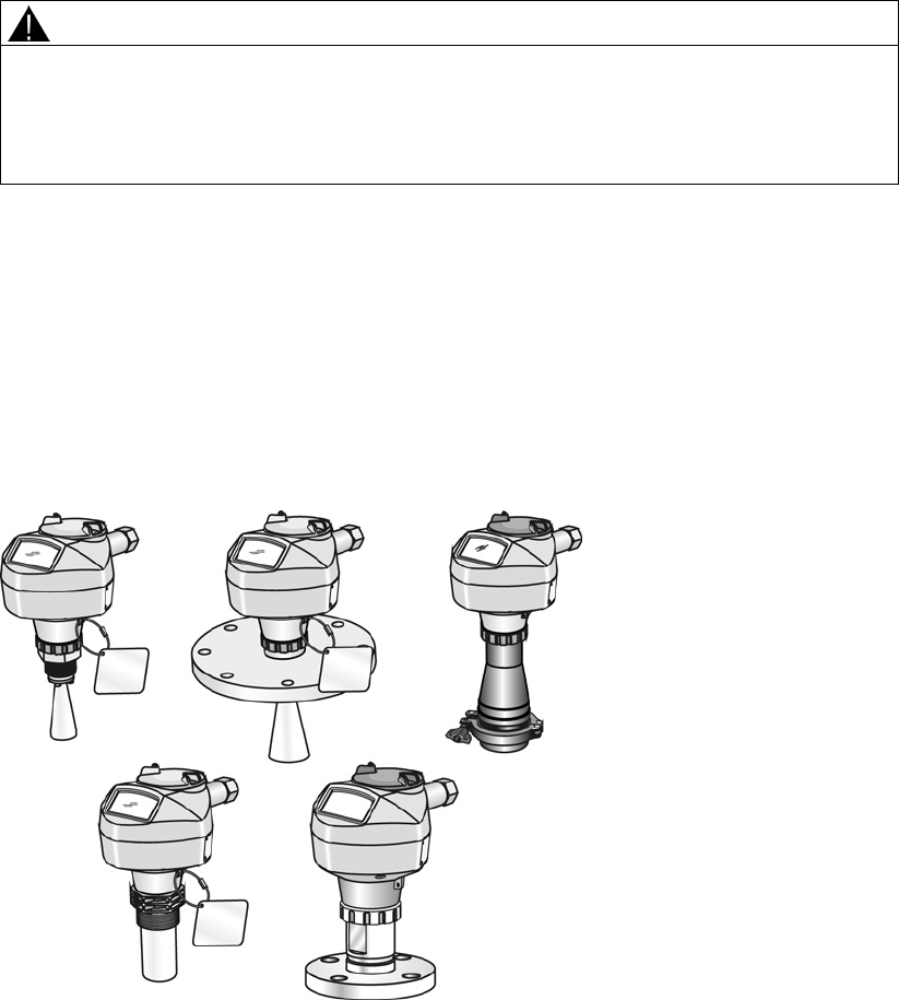
SITRANS LR250 is a 2-wire 25 GHz pulse radar level transmitter for continuous monitoring of
liquids and slurries in storage vessels including high pressure and high temperature, to a range
of 20 meters (66 feet). It is ideal for small vessels, material such as chemicals, food, beverages,
solvents (including those of corrosive or aggressive nature), and low dielectric media.
The device consists of an electronic circuit coupled to an antenna and either a threaded or
flange type process connection.
This device supports HART communication protocol. Signals are processed using Process
Intelligence which has been field-proven in over 1,000,000 applications worldwide (ultrasonic
and radar).

Description
3.2 Programming
SITRANS LR250 (mA/HART)
20 Operating Instructions, 08/2014, A5E32220602-AC
3.2
Programming
This device is very easy to install and configure via a graphical local user interface (LUI). You
can modify the built in parameters either locally via the Siemens infrared handheld programmer,
or from a remote location using one of the following options:
● SIMATIC PDM
● AMS Device Manager
● FDT/DTM platform (such as PACTware™ or FieldCare)
● HART Handheld 375/475
3.3
Applications
● liquids and slurries
● bulk storage vessels
● simple process vessels
● corrosive and aggressive
● hygienic/sanitary
3.4
Approvals and certificates
Note
For further details see
Approvals (Page 206).
SITRANS LR250 is available with approvals for General purpose, sanitary or hygienic and for
hazardous areas. In all cases, check the nameplate on your device, and confirm the approval
rating.
Process Connections
A wide range of process connections and antenna options are available to suit virtually any
vessel configuration.
SITRANS LR250 (mA/HART)
Operating Instructions, 08/2014, A5E32220602-AC 21
Installing/mounting
4
4.1
Basic safety information
Note
Material compatibility
Siemens can provide you with support concerning selection of sensor components wetted by
process media. However, you are responsible for the selection of components. Siemens
accepts no liability for faults or failures resulting from incompati
ble materials.
WARNING
Unsuitable connecting parts
Danger of injury or poisoning.
In case of improper mounting hot, toxic and corrosive process media could be released at
the connections.
• Ensure that connecting parts (such as flange gaskets and bolts) are suitable for
connection and process media.
WARNING
Exceeded maximum ambient or process media temperature
Danger of explosion in hazardous areas.
Device damage.
• Make sure that the maximum permissible ambient and process media temperatures of
the device are not exceeded.
WARNING
Open cable inlet or incorrect cable gland
Danger of explosion in hazardous areas.
• Close the cable inlets for the electrical connections. Only use cable glands or plugs
which are approved for the relevant type of protection.
Installing/mounting
4.1 Basic safety information
SITRANS LR250 (mA/HART)
22 Operating Instructions, 08/2014, A5E32220602-AC
WARNING
Incorrect conduit system
Danger of explosion in hazardous areas as result of open cable inlet or incorrect conduit
system.
• In the case of a conduit system, mount a spark barrier at a defined distance from the
device input. Observe national regulations and the requirements stated in the relevant
approvals.
4.1.1
Pressure applications
DANGER
Pressure applications
Danger to personnel, system and environment will result from improper disassembly.
• Never attempt to loosen, remove, or disassemble process connection while vessel
contents are under pressure.
WARNING
Pressure applications
Danger to personnel, system and environment can result from improper installation.
• Improper installation may result in loss of process pressure.
WARNING
Exceeded maximum permissible operating pressure
Danger of injury or poisoning.
The maximum permissible operating pressure depends on the device version. The device
can be damaged if the operating pressure is exceeded. Hot, toxic and corrosive process
media could be released.
• Make sure that the device is suitable for the maximum permissible operating pressure of
your system.

Installing/mounting
4.1 Basic safety information
SITRANS LR250 (mA/HART)
Operating Instructions, 08/2014, A5E32220602-AC 23
Note
•
The process connection tag shall remain with the process pressure boundary assembly.
(The process pressure boundary assembly comprises the components that act as a
barrier against pressure loss from the process vessel: that is, the combination of process
connection body and emitter, but normally excluding the electrical enclosure). In the
event the device package is replaced, the process connection tag shall be transferred to
the replacement unit.
•
SITRANS LR250 units are hydrostatically tested, meeting or exceeding the requirement
of the ASME Boiler and Pressure Vessel Code and the European Pressure Equipment
Directive.
Note
•
The serial numbers stamped in each process connection body, (flange, threaded, or
sanitary), provide a unique identification number indicating date of manufacture.
Example: MMDDYY – XXX (where MM = month, DD = day, YY = year, and XXX=
sequential unit produced)
•
Further markings (space permitting) indicate flange configuration, size, pressure class,
material, and material heat code.
4.1.1.1
Pressure Equipment Directive, PED, 97/23/EC
Siemens Level Transmitters with flanged, threaded, or sanitary clamp type process mounts have
no pressure-bearing housing of their own and, therefore, do not come under the Pressure
Equipment Directive as pressure or safety accessories (see EU Commission Guideline 1/8 and
1/20).
Installing/mounting
4.2 Installation location requirements
SITRANS LR250 (mA/HART)
24 Operating Instructions, 08/2014, A5E32220602-AC
4.2
Installation location requirements
WARNING
Aggressive atmospheres
Danger to personnel, system and environment can result from unsuitable environment.
• Provide an environment suitable to the housing rating and materials of construction.
CAUTION
Direct sunlight
Device damage.
The device can overheat or materials become brittle due to UV exposure.
• Protect the device from direct sunlight.
• Make sure that the maximum permissible ambient temperature is not exceeded. Refer
to the information in Chapter "Technical data (Page 199)".
Installing/mounting
4.2 Installation location requirements
SITRANS LR250 (mA/HART)
Operating Instructions, 08/2014, A5E32220602-AC 25
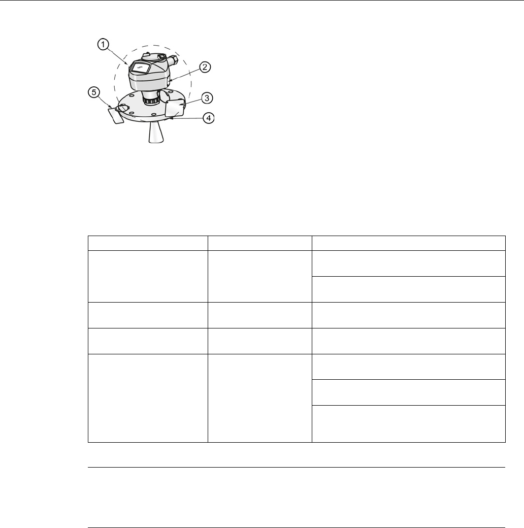
①
Ambient temperature
②
Device nameplate
③
Device tag
④
Process temperature (at process connection)
⑤
Process connection tag (contains process connection related information)
Antenna
①
③
Horn -40 to +80 °C
(-40 to +176 °F) with FKM O-ring:-40 to +200 °C (-40 to
392 °F)
with FFKM O-ring:-20 to +200 °C (-4 to
+392 °F)
PVDF -40 to +80 °C
(-40 to +176 °F)
-40 to +80 °C
(-40 to +176 °F)
Flanged encapsulated -40 to +80 °C
(-40 to +176 °F)
-40 to +170 °C
(-40 to +338 °F)
Hygienic encapsulated -40 to +80 °C
(-40 to +176 °F) -40 to +170 °C
(-40 to +338 °F)
with FKM seals used on process connection:
-20 to +170 °C (-4 to +338 °F)
with EPDM seals used on process
connection:
-40 to +120 °C (-40 to +248 °F)
Note
Details about the process connection, proc
ess temperature and materials are laser etched
into the body of the flanged and hygienic versions. All other SITRANS LR250 versions have
details listed on a tag.

Installing/mounting
4.3 Proper mounting
SITRANS LR250 (mA/HART)
26 Operating Instructions, 08/2014, A5E32220602-AC
4.3
Proper mounting
Note
•
Correct location is key to a successful application.
•
Avoid reflective interference from vessel walls and obstructions by following guidelines in
this chapter.
NOTICE
Incorrect mounting
The device can be damaged, destroyed, or its functionality impaired through improper
mounting.
• Before installing ensure there is no visible damage to the device.
• Make sure that process connectors are clean, and suitable gaskets and glands are
used.
• Mount the device using suitable tools. Refer to the information in Installation instructions
(Page 34) for installation torque requirements.
Note
•
On devices with a removable head, there is no limit to the number of times a device can
be rotated without damage.
•
When mounting, orient the front or back of the device towards the closest vessel wall or
obstruction.
•
Do not rotate the enclosure after programming and vessel calibration, otherwise an error
may occur, caused by a polarity shift of the transmit pulse.
Installing/mounting
4.3 Proper mounting
SITRANS LR250 (mA/HART)
Operating Instructions, 08/2014, A5E32220602-AC 27
4.3.1
Nozzle design
Threaded PVDF antenna
Stainless steel horn antenna
Flanged encapsulated antenna (FEA)
Hygienic encapsulated antenna (HEA)
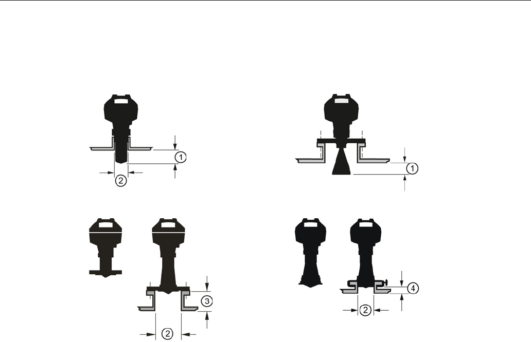
①
Minimum clearance: 10 mm (0.4")
②
Minimum diameter: 50 mm (2")
③
Maximum nozzle length
④
Maximum length/diameter ratio 1:1
● The end of the antenna must protrude a minimum of 10 mm (0.4") to avoid false echoes
being reflected from the nozzle1).
● Minimum recommended nozzle diameter for the threaded PVDF antenna is 50 mm (2").
● An antenna extension (100 mm/3.93") is available for the horn antenna only.
● The maximum nozzle length for the FEA is 500 mm (19.68") when the nozzle diameter is
DN150 (6"). Only shorter lengths are recommended for smaller diameters.
● When installing the SITRANS LR250 with hygienic process connection, it is good hygienic
practice to install the antenna in a nozzle that has a maximum length/diameter ratio of 1:1.
For example, 2" (DN50) diameter nozzle should be no longer than 2" (50 mm).
● When removing any sanitary/hygienic clamp version of the HEA to clean the lens, ensure it is
re-installed in the exact position it was removed from, to avoid re-commissioning the device.
1) Not applicable for FEA or HEA
Installing/mounting
4.3 Proper mounting
SITRANS LR250 (mA/HART)
28 Operating Instructions, 08/2014, A5E32220602-AC
4.3.2
Nozzle location
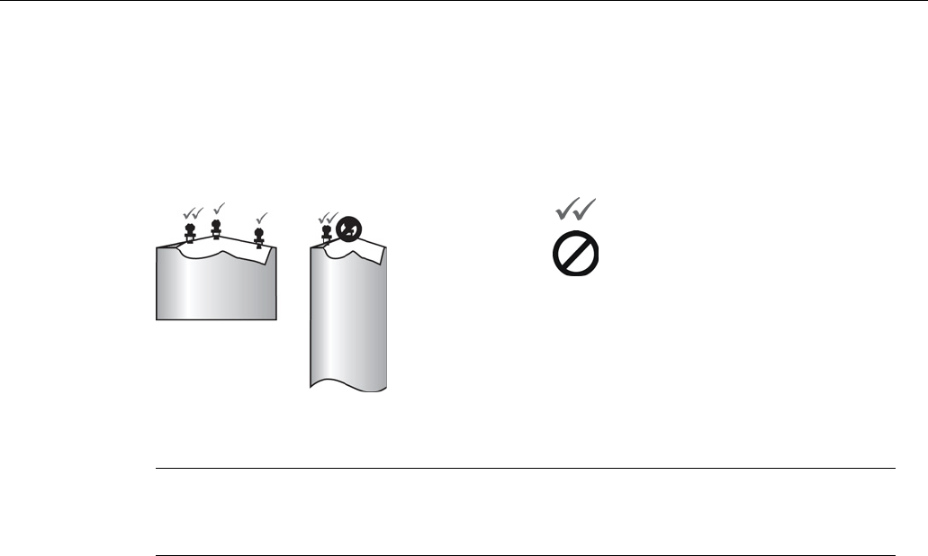
● Avoid central locations on tall, narrow vessels
● Nozzle must be vertical and clear of imperfections
Preferred
Undesirable
Beam angle
Note
•
Beam width depends on antenna size and is approximate: see below.
•
For details on avoiding false echoes, see Auto False Echo Suppression (Page 259).
● Beam angle is the width of the cone where the energy density is half of the peak energy
density.
● The peak energy density is directly in front of and in line with the antenna.
● There is a signal transmitted outside the beam angle, therefore false targets may be
detected.
Installing/mounting
4.3 Proper mounting
SITRANS LR250 (mA/HART)
Operating Instructions, 08/2014, A5E32220602-AC 29
Horn antenna
Flanged encapsulated antenna
Threaded PVDF antenna
Hygienic encapsulated antenna
①
Emission cone
②
Beam angle

Installing/mounting
4.3 Proper mounting
SITRANS LR250 (mA/HART)
30 Operating Instructions, 08/2014, A5E32220602-AC
Emission cone type and beam angle
Antenna type
Antenna size
Beam angle
Horn
1.5"
19°
2"
15°
3"
10°
4"
8°
Threaded PVDF
19°
Process connection
size
Process connection type
Flanged encapsulated
2"
Class 150 ASME B16.5
12.8°
3, 4, 6"
Class 150 ASME B16.5
9.6°
50A
10K JIS B 2220
12.8°
80A/100A/150A
10K JIS B 2220
9.6°
DN50
PN10/16 EN1092-1
12.8°
DN80/DN100/DN15
0
PN10/16 EN1092-1 9.6°
Hygienic encapsulated
2"
Sanitary Clamp according to
ISO 2852
12.8°
3, 4"
9.6°
DN50
Aseptic/Hygienic nozzle/slotted
nut according to DIN 11864-1
[Form A]
12.8°
DN80/DN100 9.6°
DN50
Aseptic/Hygienic flanged
according to DIN 11864-2
[Form A]
12.8°
DN80/DN100 9.6°
DN50
Aseptic/Hygienic Clamp
according to DIN 11864-
3 [Form A]
12.8°
DN80/DN100 9.6°
DN50
Hygienic nozzle/slotted nut
according to DIN 11851
12.8°
DN80/DN100
9.6°
Type F (50 mm)
and Type N
(68 mm)
Tuchenhagen Varivent 12.8°
Emission cone
● Keep emission cone free of interference from obstructions such as ladders, pipes, I-beams,
or filling streams.
Access for programming
● Provide easy access for viewing the display and programming via the handheld programmer.

Installing/mounting
4.3 Proper mounting
SITRANS LR250 (mA/HART)
Operating Instructions, 08/2014, A5E32220602-AC 31
4.3.3
Orientation in a vessel with obstructions
Polarization reference point
For best results on a vessel with obstructions, or a stillpipe with openings, orient the front or
back of the device toward the obstructions. For an illustration, see Device orientation (Page 33).
①
Polarization axis
②
Polarization reference point
③
Display

Installing/mounting
4.3 Proper mounting
SITRANS LR250 (mA/HART)
32 Operating Instructions, 08/2014, A5E32220602-AC
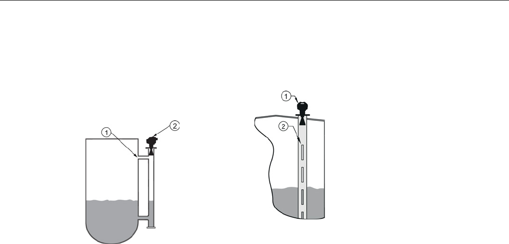
4.3.4
Mounting on a Stillpipe or Bypass Pipe
A stillpipe or bypass pipe is used for products with a low dK, or when vortex or extremely
turbulent conditions exist. It can also be used to provide optimum signal conditions on foaming
materials. See Dielectric constant of material measured in Performance (Page 199) for more
information.
● The pipe diameter must be matched with the antenna size. Use the largest antenna size that
will fit the stillpipe/bypass pipe1). See Threaded Horn dimensions, Raised-Face Flange per
EN 1092-1 (Page 243), Flanged encapsulated dimensions (Page 218)or Hygienic
encapsulated dimensions (Page 222).
● One continuous length of metallic pipe is preferred, without joints.
● Any false reflections created by joints/welds/imperfections will lead to inaccuracies of the
measurement.
● Joints (if unavoidable) must be machined to ± 0.25 mm (± 0.010") and must have welded
connecting sleeve on the outside.
● If using any hygienic process connections in conjunction with a stillpipe/bypass, please
ensure that the antenna/lens are cleanable in accordance with the applicable approval.
1) Mounting in a pipe greater than 100 mm (4") can cause large errors, and therefore is not
recommended.
Suitable pipe diameters:
Horn antenna
40 to 100 mm (1.5 to 4")
PVDF antenna
50 mm (2") only
Flanged encapsulated antenna
50 to 100 mm (2 to 4")
Hygienic encapsulated antenna
50 to 100 mm (2 to 4")
Not recommended:
> 100 mm (4")
Bypass vent:
Required at the upper end of the bypass
1)
1)
To equalize pressure and keep the liquid level in the bypass constant with the liquid level in the
vessel.
Installing/mounting
4.3 Proper mounting
SITRANS LR250 (mA/HART)
Operating Instructions, 08/2014, A5E32220602-AC 33
4.3.5
Device orientation
Bypass pipe installation
Stillpipe installation
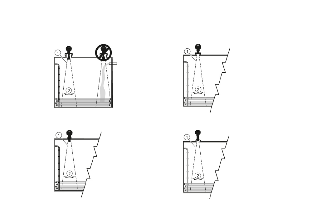
①
Vent
①
Align front or back of device with stillpipe slots
1)
②
Align front or back of device with
vents
1)
②
Slots
1) Horn antenna version shown as example

Installing/mounting
4.4 Installation instructions
SITRANS LR250 (mA/HART)
34 Operating Instructions, 08/2014, A5E32220602-AC
4.4
Installation instructions
WARNING
Pressure applications
Danger to personnel, system and environment can result from improper installation.
• Improper installation may result in loss of process pressure.
WARNING
Improper installation
Danger to personnel, system and environment can result from improper installation.
• Installation shall only be performed by qualified personnel and in accordance with local
governing regulations.
NOTICE
Device handling
Damage to device may result from improper handling.
• Handle the device using the enclosure, not the process connection or tag, to avoid
damage.
• Take special care when handling the threaded PVDF and Hygienic or Flanged
encapsulated antennas. Any damage to the antenna surface, particularly to the tip/lens,
could affect performance. (For example, do not sit device on its lens antenna.)
Note
•
For European Union and member countries, installation must be according to
ETSI EN 302372.
•
Refer to the device nameplate for approval information.
Note
The outer part of the lens on the flanged encapsulated antenna version may not appear to lie
flush before installation and this is normal. This will flatten after installation and will not
impact the performance of the device.
Installing/mounting
4.4 Installation instructions
SITRANS LR250 (mA/HART)
Operating Instructions, 08/2014, A5E32220602-AC 35
4.4.1
Threaded versions
WARNING
Pressure applications
Danger of injury or poisoning.
It may be necessary to use PTFE tape or other appropriate thread sealing compound, and
to tighten the process connection beyond hand-tight. (The maximum recommended torque
for Threaded versions is 40 N-m (30 ft.lbs.)
1. Before inserting the device into its mounting connection, check to ensure the threads are
matching, to avoid damaging them.
2. Simply screw the device into the process connection, and hand tighten, or use a wrench.
4.4.2
Flanged versions
NOTICE
Improper materials
The user is responsible for the selection of bolting and gasket materials (except for Flanged
encapsulated antenna) which will fall within the limits of the process connection and its
intended use, and which are suitable for the service conditions.
Special Instructions for Flanged encapsulated antenna only
Note
•
Use spring washers
•
Lens assembly acts as integral gasket, no other required
•
Use recommended torque values for tightening bolts

Installing/mounting
4.4 Installation instructions
SITRANS LR250 (mA/HART)
36 Operating Instructions, 08/2014, A5E32220602-AC
Flange bolting: recommended torque
Pressure class
Nominal pipe size
(NPS)
Number of bolts
Recommended torque
(Nm)
ASME B16.5, Class
150
2"
4
30 – 50
3"
50 – 70
4"
8
40 – 60
6"
70 – 90
EN1092-1, PN16 /
JIS B 2220, 10K
DN50/50A
4
30 – 50
DN80/80A
8
DN100/100A
DN150/150A
60 – 80
Installing/mounting
4.4 Installation instructions
SITRANS LR250 (mA/HART)
Operating Instructions, 08/2014, A5E32220602-AC 37
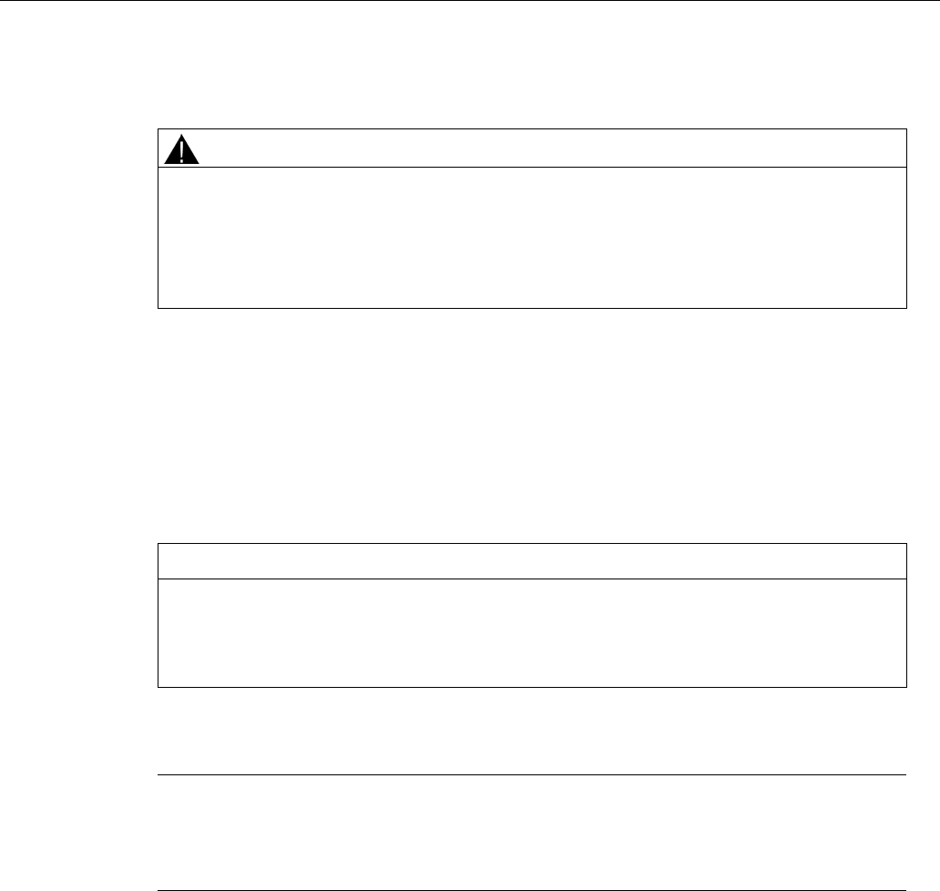
Flange bolting instructions:
1. Use cross-pattern sequence as shown.
2. Check uniformity of the flange gap.
3. Apply adjustments by selective tightening if required.
4. Torque incrementally until desired value is reached.
5. Check/re-torque after 4 to 6 hours.
Recommendations for flange bolting:
● Check bolts periodically, re-torque as required.
● Use new lens, O-ring and spring washers after removal from installation.
For instructions on replacing the lens, see Part replacement (Page 185).
See Flanged Horn with extension (Page 214), Raised-Face Flange per EN 1092-1 (Page 243),
Flat-Face Flange (Page 246), and Flanged encapsulated antenna (3"/DN80/80A sizes and
larger) (Page 220) for dimensions.
Installing/mounting
4.4 Installation instructions
SITRANS LR250 (mA/HART)
38 Operating Instructions, 08/2014, A5E32220602-AC
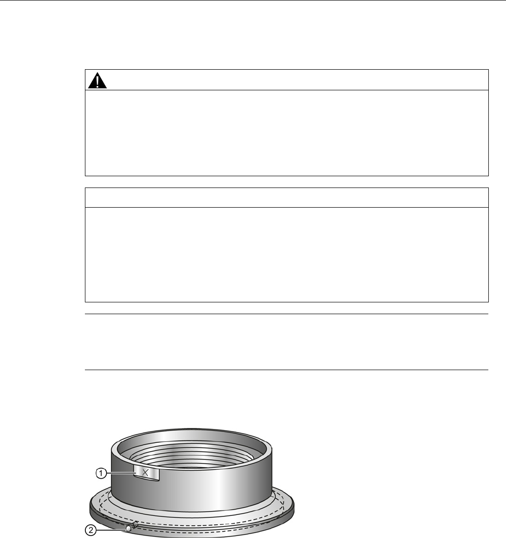
4.4.3
Hygienic versions
WARNING
Loss of sanitary approvals
Loss of sanitary approvals can result from improper installation/mounting.
• Take special care when installing in hygienic or sanitary applications. Comply with
installation/mounting guidelines to ensure cleanliness and the ability to keep the wetted
parts in a position to be readily cleanable. (See relevant EHEDG/3A documentation - not
supplied).
NOTICE
Loss of sanitary approvals
• For 3-A Sanitary Approved device installation where the customer tank process
connection exists, a leak detection port of minimum 2.4 mm diameter must be provided
at the lowest point in the process connection where leakage can occur.
• If leakage is detected at any time while the device is installed, then the device process
connection parts must be disassembled and thoroughly cleaned prior to gasket
replacement and reassembly.
Note
•
For Hygienic encapsulated antenna, the lens acts as a gasket/seal and should be used in
conjunction with a cleanable seal as required by the specific process connections (for
example, DIN 11864-3).
Hygienic encapsulated antenna leak detection port
①
Orientation mark for leak detection
port
②
Leak detection port
Installing/mounting
4.5 Disassembly
SITRANS LR250 (mA/HART)
Operating Instructions, 08/2014, A5E32220602-AC 39
4.5
Disassembly
DANGER
Pressure applications
Danger to personnel, system and environment will result from improper disassembly.
• Never attempt to loosen, remove, or disassemble process connection while vessel
contents are under pressure.
WARNING
Incorrect disassembly
The following dangers may result through incorrect disassembly:
- Injury through electric shock
- Danger through emerging media when connected to the process
- Danger of explosion in hazardous area
In order to disassemble correctly, observe the following:
• Before starting work, make sure that you have switched off all physical variables such
as pressure, temperature, electricity etc. or that they have a harmless value.
• If the device contains dangerous media, it must be emptied prior to disassembly. Make
sure that no environmentally hazardous media are released.
• Secure the remaining connections so that no damage can result if the process is started
unintentionally.

Installing/mounting
4.5 Disassembly
SITRANS LR250 (mA/HART)
40 Operating Instructions, 08/2014, A5E32220602-AC

SITRANS LR250 (mA/HART)
Operating Instructions, 08/2014, A5E32220602-AC 41
Connecting
5
5.1
Basic safety information
NOTICE
Condensation in the device
Damage to device through formation of condensation if the temperature difference between
transportation or storage and the mounting location exceeds 20 °C (68°F).
• Before taking the device into operation let the device adapt for several hours in the new
environment.
WARNING
Missing PE/ground connection
Danger of electric shock.
Depending on the device version, connect the power supply as follows:
•
Power plug
: Ensure that the used socket has a PE/ground conductor connection. Check
that the PE/ground conductor connection of the socket and power plug match each
other.
•
Connecting terminals
: Connect the terminals according to the terminal connection
diagram. First connect the PE/ground conductor.
5.2
Connecting SITRANS LR250
WARNING
Incorrect connection to power source
Danger to personnel, system and environment can result from improper power connection.
• The DC input terminals shall be supplied from a source providing electrical isolation
between the input and output, in order to meet the applicable safety requirements of
IEC 61010-1.
• All field wiring must have insulation suitable for rated voltages.

Connecting
5.2 Connecting SITRANS LR250
SITRANS LR250 (mA/HART)
42 Operating Instructions, 08/2014, A5E32220602-AC
WARNING
Loss of protection
Loss of approvals can result from improper installation.
• Check the nameplate on your device, to verify the approval rating.
• Use appropriate conduit seals to maintain IP or NEMA rating.
• See Wiring setups for hazardous area installations (Page 45).
NOTICE
Improper cables and conduit
• Separate cables and conduits may be required to conform to standard instrumentation
wiring practices or electrical codes.
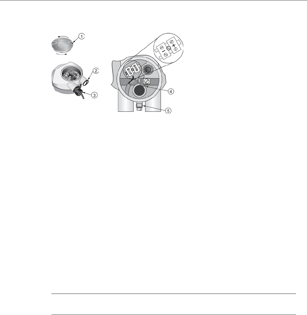
Connecting
5.2 Connecting SITRANS LR250
SITRANS LR250 (mA/HART)
Operating Instructions, 08/2014, A5E32220602-AC 43
①
Use a 2 mm Allen key to loosen the lid
-lock set screw c)
④
Cable shield
②
Plug (IP68)
⑤
Ground terminal
③
Optional cable gland
a) b) (or NPT cable entry)b)
a)
May be shipped with the device.
b)
If cable is routed through conduit, use only approved suitable-size hubs for waterproof
applications.
c) Not applicable to 3-A Sanitary approved device.
Wiring instructions
1. Strip the cable jacket for approximately 70 mm (2.75") from the end of the cable, and thread
the wires through the gland. (If cable is routed through conduit, use only approved suitable-
size hubs for waterproof applications.)
2. Connect the wires to the terminals as shown: the polarity is identified on the terminal block.
3. Ground the device according to local regulations.
4. Tighten the gland to form a good seal.
5. Close the lid and secure the locking screw before programming and device configuration.
Note
Lid
-lock set screw not applicable to 3-A Sanitary approved device.
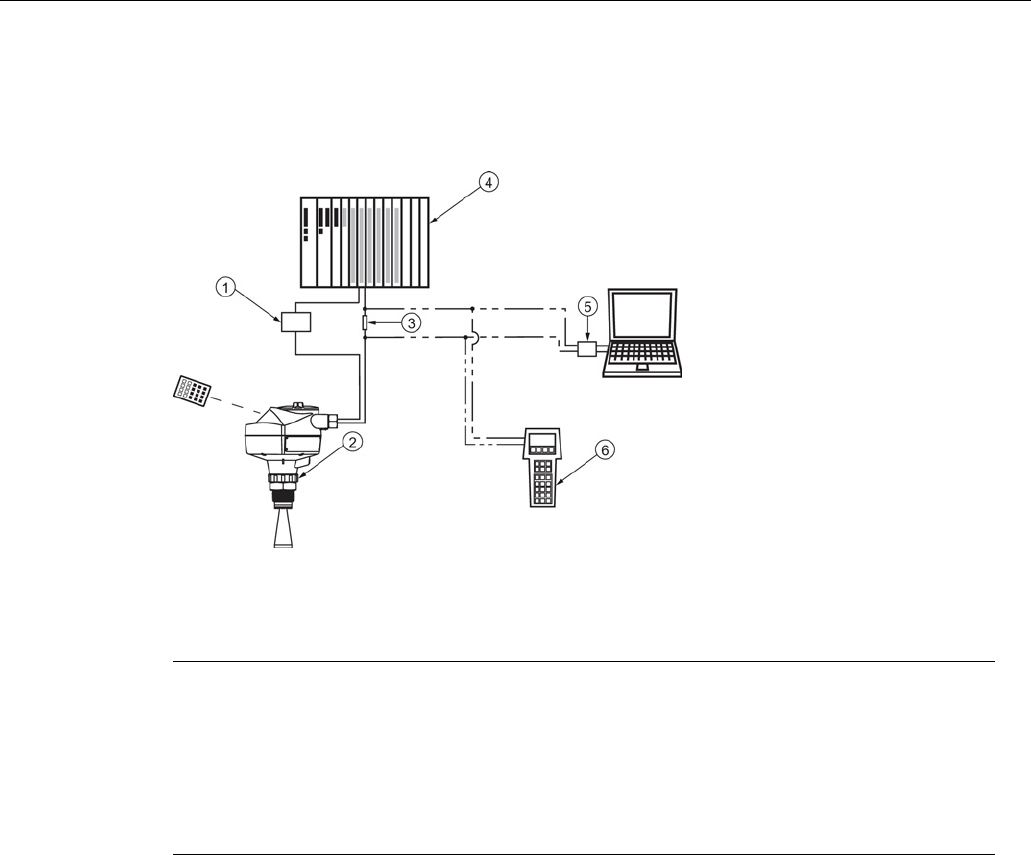
Connecting
5.2 Connecting SITRANS LR250
SITRANS LR250 (mA/HART)
44 Operating Instructions, 08/2014, A5E32220602-AC
Connecting HART
Typical PLC/mA configuration with HART
①
Power supply
④
Active PLC
②
SITRANS LR250
⑤
HART modem
③
R = 250 Ω
⑥
HART communicator
Note
•
Depending on the system design, the power supply may be separate from the PLC, or
integral to it.
•
HART resistance (total loop resistance, that is, cable resistance plus 250 Ohm [resistor])
must be limited according to the allowable operating area as shown in either Curve 1
(Page 282) (General Purpose, Intrinsically Safe, Non-Sparking, Non-incendive) or Curve
2 (Page 283) (Flameproof, Increased Safety, Explosion-proof).
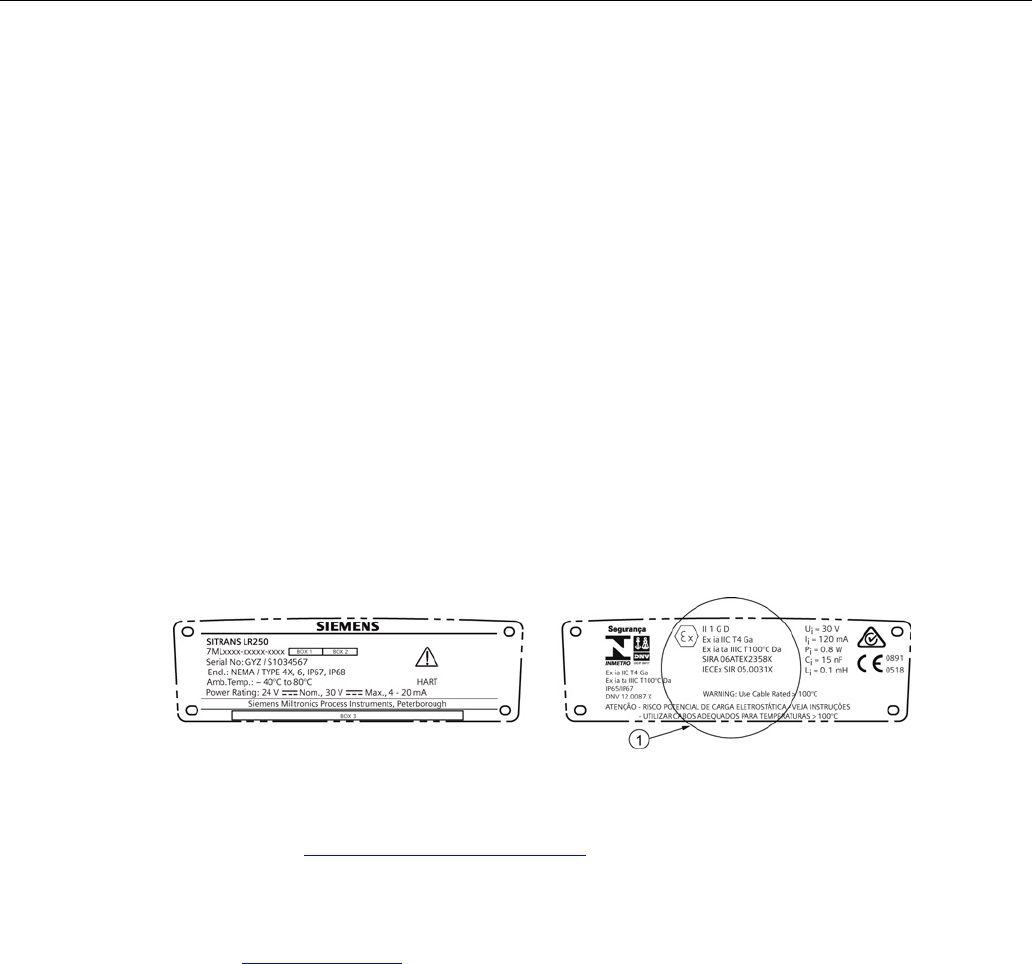
Connecting
5.3 Wiring setups for hazardous area installations
SITRANS LR250 (mA/HART)
Operating Instructions, 08/2014, A5E32220602-AC 45
5.3
Wiring setups for hazardous area installations
There are six wiring options for hazardous area installations:
● Intrinsically Safe wiring (Page 45)
● Non-Sparking wiring (Page 47)
● Non-incendive wiring (US/Canada only) (Page 47)
● Flameproof wiring (Page 48)
● Increased safety wiring (Page 49)
● Explosion-proof wiring (US/Canada only) (Page 49)
In all cases, check the nameplate on your instrument, confirm the approval rating, and perform
installation and wiring according to your local safety codes.
5.3.1
Intrinsically safe wiring
Device nameplate (ATEX/IECEX/INMETRO/RCM)
①
ATEX certificate
The ATEX certificate listed on the nameplate can be downloaded from our website:
Product page (http://www.siemens.com/LR250)
Go to
Support > Approvals / Certificates.
The IECEx certificate listed on the nameplate can be viewed on the IECEx website. Go to:
IECEx (http://iecex.iec.ch/)
Click on
Certified Equipment
then enter the certificate number IECEx SIR 05.0031X.
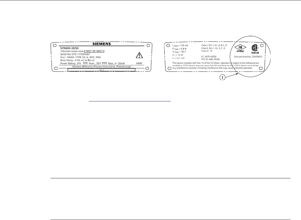
Connecting
5.3 Wiring setups for hazardous area installations
SITRANS LR250 (mA/HART)
46 Operating Instructions, 08/2014, A5E32220602-AC
Device nameplate (FM/CSA)
The connection drawing number listed on the nameplate can be downloaded from our website:
Product page (http://www.siemens.com/LR250)
Go to
Support > Installation Drawings > Level Measurement > SITRANS LR250
.
● For power demands see Curve 1 (General Purpose, Intrinsically Safe, Non-Sparking, Non-
incendive) (Page 282).
● For wiring requirements: follow local regulations.
● Approved dust-tight and water-tight conduit seals are required for outdoor NEMA 4X / type 4X
/ NEMA 6, IP67, IP68 locations.
● Refer to Instructions specific to hazardous area installations (Page 50).
Note
Selecting a
suitable PLC input module or power supply requires knowledge about Intrinsic
Safety and the application. It is the responsibility of the installer to ensure that the intrinsically
safe installation complies with both the apparatus approval requirements an
d the relevant
national code of practice.
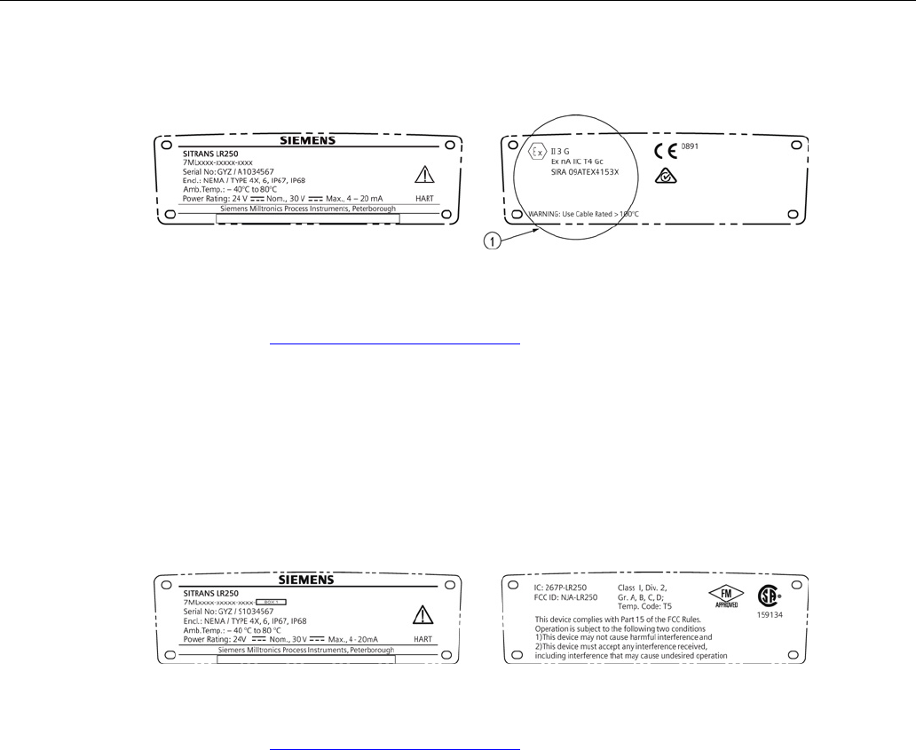
Connecting
5.3 Wiring setups for hazardous area installations
SITRANS LR250 (mA/HART)
Operating Instructions, 08/2014, A5E32220602-AC 47
5.3.2
Non-sparking wiring
①
ATEX certificate
The ATEX certificate listed on the nameplate can be downloaded from our website:
Product page (http://www.siemens.com/LR250)
Go to:
Support > Approvals / Certificates
.
● For power demands see Curve 1 (General Purpose, Intrinsically Safe, Non-Sparking/Energy
Limited, Non-incendive) (Page 282).
● For wiring requirements follow local regulations.
5.3.3
Non-incendive wiring (US/Canada only)
The FM/CSA Class 1, Div 2 connection drawing number 23650673 can be downloaded from our
website:
Product page (http://www.siemens.com/LR250)
Go to
Support > Installation Drawings > Level Measurement > SITRANS LR250.
● For power demands see Curve 1 (General Purpose, Intrinsically Safe, Non-Sparking, Non-
incendive) (Page 282).
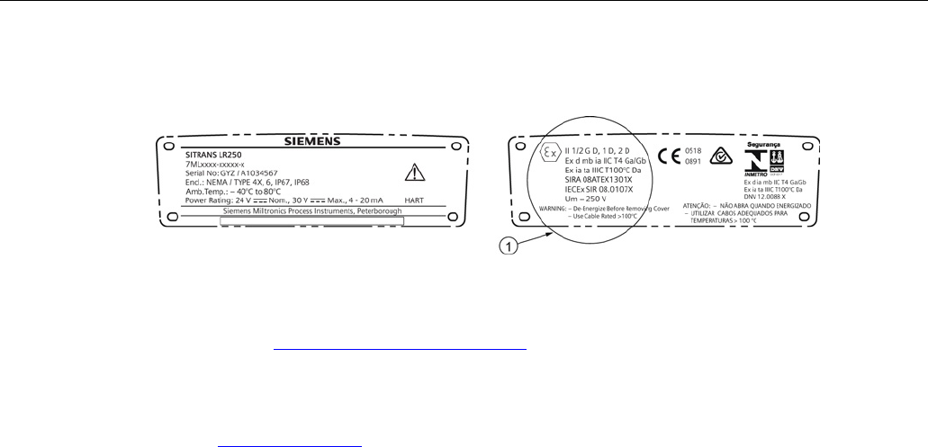
Connecting
5.3 Wiring setups for hazardous area installations
SITRANS LR250 (mA/HART)
48 Operating Instructions, 08/2014, A5E32220602-AC
5.3.4
Flameproof wiring
①
ATEX certificate
The ATEX certificate listed on the nameplate can be downloaded from our website:
Product page (http://www.siemens.com/LR250)
Go to
Support > Approvals / Certificates
.
The IECEx certificate listed on the nameplate can be viewed on the IECEx website. Go to:
IECEx (http://iecex.iec.ch/)
Click on
Certified Equipment
then enter the certificate number IECEx SIR 08.0107X.
● For power demands see Curve 2 (Flameproof, Increased Safety, Explosion-proof)
(Page 283).
● For wiring requirements follow local regulations.
● See also Instructions specific to hazardous area installations (Page 50) and the ATEX
certificate listed above.
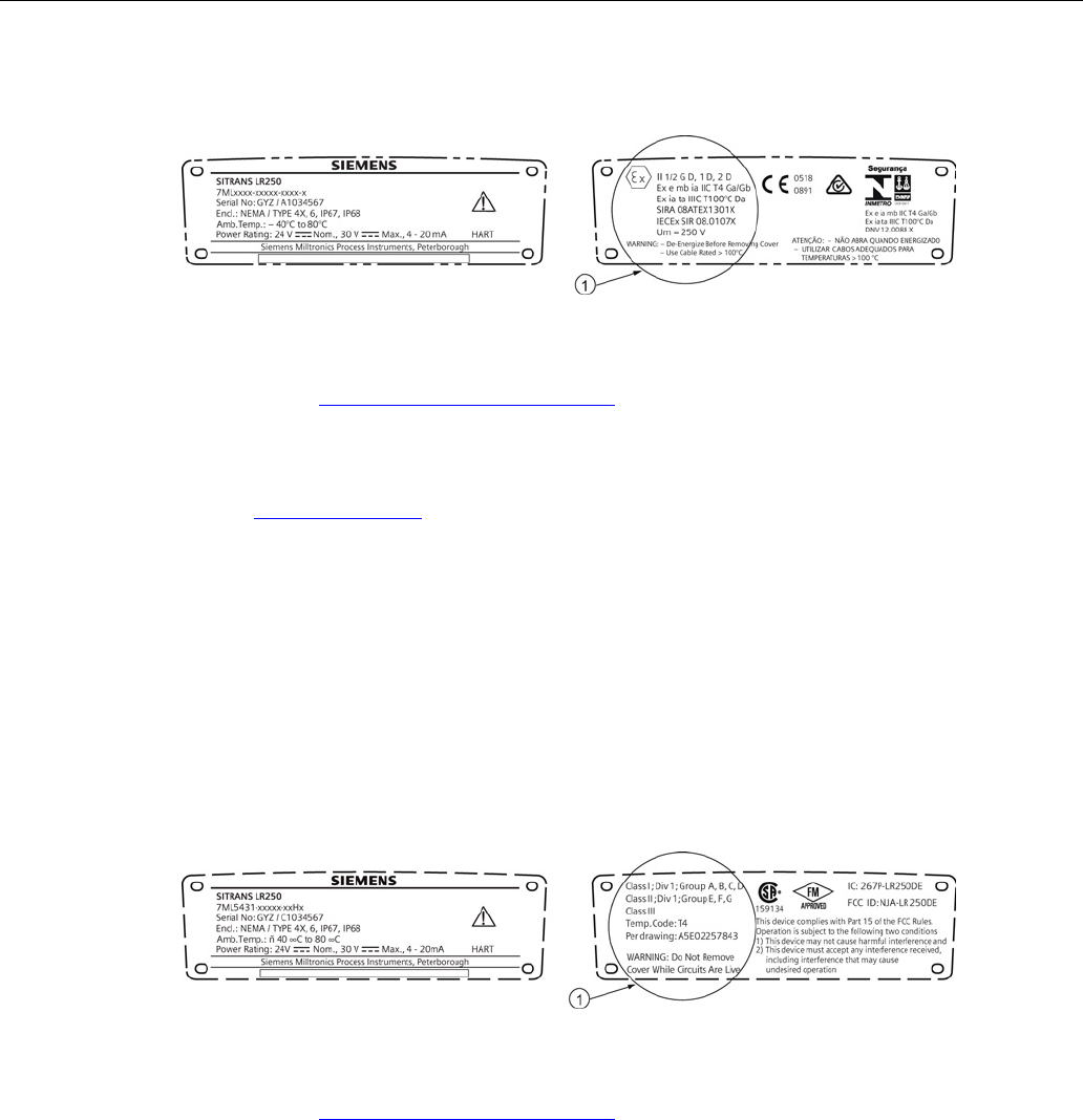
Connecting
5.3 Wiring setups for hazardous area installations
SITRANS LR250 (mA/HART)
Operating Instructions, 08/2014, A5E32220602-AC 49
5.3.5
Increased safety wiring
①
ATEX certificate
The ATEX certificate listed on the nameplate can be downloaded from our website:
Product page (http://www.siemens.com/LR250)
Go to
Support > Approvals / Certificates
.
The IECEx certificate listed on the nameplate can be viewed on the IECEx website:
IECEx (http://iecex.iec.ch/)
Click on
Certified Equipment
then enter the certificate number IECEx SIR 08.0107X.
● For power demands see Curve 2 (Flameproof, Increased Safety, Explosion-proof)
(Page 283).
● For wiring requirements follow local regulations.
● See also Instructions specific to hazardous area installations (Page 50) and the ATEX
certificate listed above.
5.3.6
Explosion-proof wiring (US/Canada only)
①
FM/CSA Explosion Proof connection drawing
The connection drawing number listed on the nameplate can be downloaded from our website:
Product page (http://www.siemens.com/LR250)
Go to
Support > Installation Drawings > Level Measurement > SITRANS LR250
● For power demands see Curve 2 (Flameproof, Increased Safety, Explosion-proof)
(Page 283).

Connecting
5.4 Instructions specific to hazardous area installations
SITRANS LR250 (mA/HART)
50 Operating Instructions, 08/2014, A5E32220602-AC
5.4
Instructions specific to hazardous area installations
5.4.1
(Reference European ATEX Directive 94/9/EC, Annex II, 1/0/6)
The following instructions apply to equipment covered by certificate number SIRA
06ATEX2358X, SIRA 08ATEX1301X, and SIRA 09ATEX4153X.
1. For use and assembly, refer to the main instructions.
2. The equipment is certified for use as Category 1GD equipment per SIRA 06ATEX2358X;
Category 1/2 GD, 1D, 2D equipment per SIRA 08ATEX1301X; and Category 3G equipment
per SIRA 09ATEX4153X.
3. The equipment may be used with flammable gases and vapors with apparatus group IIC, IIB
and IIA and temperature classes T1, T2, T3 and T4.
4. The equipment has a degree of ingress protection of IP67 and a temperature class of T100
°C and may be used with flammable dusts.
5. The equipment is certified for use in an ambient temperature range of –40 °C to +80 °C.
6. The equipment has not been assessed as a safety related device (as referred to by Directive
94/9/EC Annex II, clause 1.5).
7. Installation and inspection of this equipment shall be carried out by suitably trained personnel
in accordance with the applicable code of practice (EN 60079-14 and EN 60079-17 in
Europe).
8. The equipment is non-repairable.
9. The certificate numbers have an ‘X’ suffix, which indicates that special conditions for safe use
apply. Those installing or inspecting this equipment must have access to the certificates.
10.If the equipment is likely to come into contact with aggressive substances, then it is the
responsibility of the user to take suitable precautions that prevent it from being adversely
affected, thus ensuring that the type of protection is not compromised.
– Aggressive substances: for example, acidic liquids or gases that may attack metals, or
solvents that may affect polymeric materials.
– Suitable precautions: for example, establishing from the material’s data sheet that it is
resistant to specific chemicals.

Connecting
5.4 Instructions specific to hazardous area installations
SITRANS LR250 (mA/HART)
Operating Instructions, 08/2014, A5E32220602-AC 51
Special conditions for safe use (denoted by X after the certificate number)
● Parts of the enclosure may be non-conducting and may generate an ignition-capable level of
electrostatic charge under certain extreme conditions. The user should ensure that the
equipment is not installed in a location where it may be subjected to external conditions (such
as high-pressure steam), which might cause a build-up of electrostatic charge on non-
conducting surfaces.
● Aluminium, magnesium, titanium or zirconium may be used at the accessible surface of the
equipment. In the event of rare incidents, ignition sources due to impact and friction sparks
could occur. This shall be considered when the SITRANS LR250 mA/HART is being installed
in locations that specifically require group II, level of protection Ga or Da.
● The equipment shall be bonded to the system earth in accordance with the relevant code of
practice.
● When the SITRANS LR250 mA/HART is used in the presence of combustible dust, the gland
that is fitted to the equipment shall also be suitable for use in the presence of combustible
dust, as certified by an ATEX notified body, in addition, the installation of the gland shall not
compromise the IP6X rating of the equipment enclosure.

Connecting
5.4 Instructions specific to hazardous area installations
SITRANS LR250 (mA/HART)
52 Operating Instructions, 08/2014, A5E32220602-AC

SITRANS LR250 (mA/HART)
Operating Instructions, 08/2014, A5E32220602-AC 53
Commissioning
6
6.1
Basic safety information
WARNING
Loss of explosion protection
Danger of explosion when device is not properly commissioned
If opening device
• Isolate from power.
- or -
• Ensure that the atmosphere is explosion-free (hot work permit).
Ensure device is properly closed before returning to operation.
6.2
Operating via the handheld programmer
The handheld programmer used with this device contains lithium batteries that are non-
replaceable.
Lithium batteries are primary power sources with high energy content designed to represent the
highest possible degree of safety.
WARNING
Potential hazard
Lithium batteries may present a potential hazard if they are abused electrically or
mechanically.
• Observe the following precautions when handling and using lithium batteries:
– Do not short-circuit, recharge or connect with false polarity.
– Do not expose to temperature beyond the specified temperature range or incinerate
the battery.
– Do not crush, puncture or open cells or disassemble battery packs.
– Do not weld or solder to the battery’s body.
–
Do not expose contents to water.

Commissioning
6.2 Operating via the handheld programmer
SITRANS LR250 (mA/HART)
54 Operating Instructions, 08/2014, A5E32220602-AC
6.2.1
Power up
Power up the device. A transition screen showing first the Siemens logo and then the current
firmware revision is displayed while the first measurement is being processed. The first time the
device is configured, you will be prompted to select a language (English, German, French, or
Spanish). To change the language again, see
Language (7.)
.
Press
Mode
to toggle between Measurement and Program mode.
6.2.2
Handheld programmer functions
The radar device carries out its level measurement tasks according to settings made via
parameters. The settings can be modified locally via the Local User Interface (LUI) which
consists of an LCD display and a handheld programmer.
A Quick Start Wizard provides an easy step-by-step procedure to configure the device for a
simple application. Access the wizards:
● locally [see Quick Start Wizard via the handheld programmer (Page 64)]
● or from a remote location [see Quick Start Wizard via SIMATIC PDM (Page 81),
or Quick Start Wizard via AMS Device Manager (Page 107)]
For more complex setups see Application Examples (Page 70), and for the complete range of
parameters see Parameter Reference (Page 127).
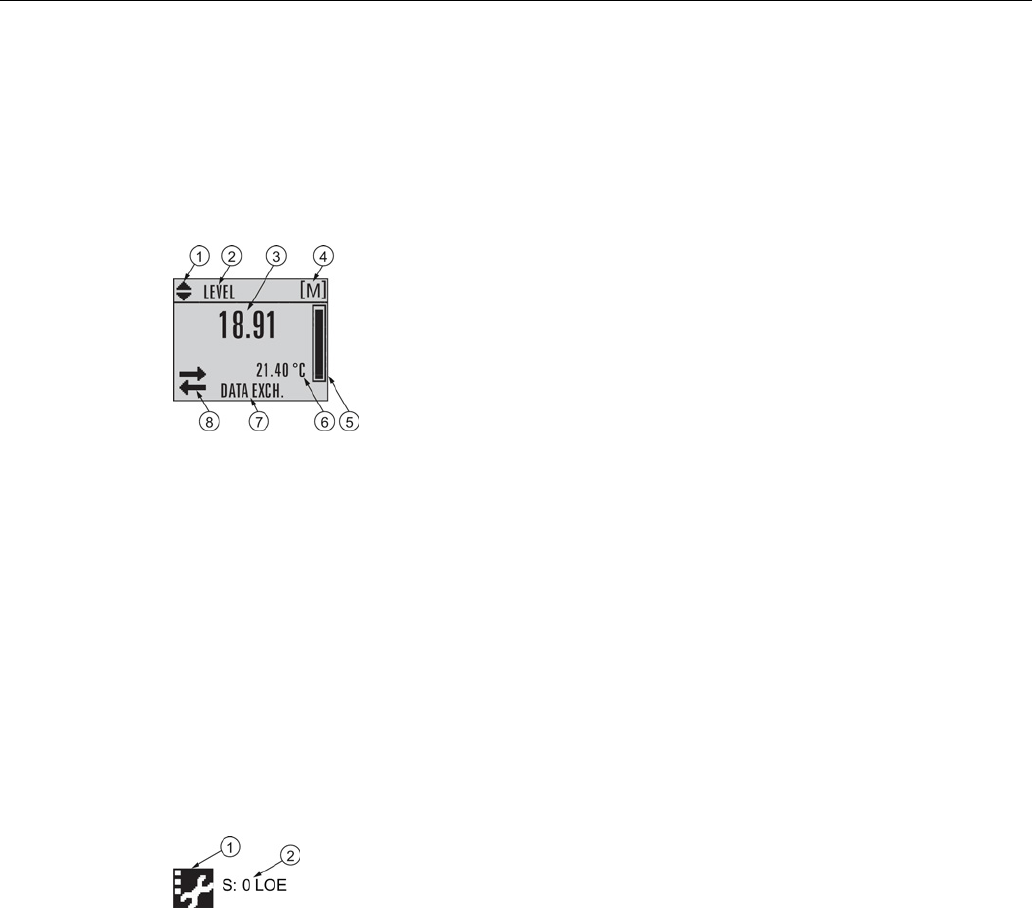
Commissioning
6.2 Operating via the handheld programmer
SITRANS LR250 (mA/HART)
Operating Instructions, 08/2014, A5E32220602-AC 55
6.2.2.1
The LCD display
Measurement mode display
Normal operation
①
Toggle indicator
a)
for linear units or %
②
Selected operation: level, space, distance, or volume
③
Measured value (level, space, distance, or volume)
④
Units
⑤
Bar graph indicates level
⑥
Secondary region indicates on request b) electronics temperature, echo confidence, loop
current, or distance
⑦
Text area displays status messages
⑧
Device status indicator, see Device status icons (Page 190)
a)
Press UP or DOWN arrow to switch.
b) In response to a key press request. For details, see Handheld Programmer (Page 57) for key
functions in Measurement mode.
Fault present
①
Device status indicator, see Device status icons (Page 190)
②
Text area displays status messages
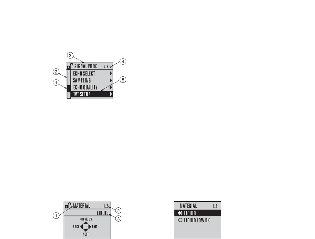
Commissioning
6.2 Operating via the handheld programmer
SITRANS LR250 (mA/HART)
56 Operating Instructions, 08/2014, A5E32220602-AC
PROGRAM mode display
Navigation view
①
Item band
④
Current item number
②
Menu bar
⑤
Current item
③
Current menu
● A visible menu bar indicates the menu list is too long to display all items.
● A band halfway down the menu bar indicates the current item is halfway down the list.
● The depth and relative position of the item band on the menu bar indicates the length of the
menu list, and approximate position of the current item in the list.
● A deeper band indicates fewer items.
Parameter view
Edit view
①
Parameter name
②
Parameter number
③
Parameter value/selection

Commissioning
6.2 Operating via the handheld programmer
SITRANS LR250 (mA/HART)
Operating Instructions, 08/2014, A5E32220602-AC 57
6.2.2.2
Handheld programmer (Part No. 7ML1930-1BK)
The programmer is ordered separately.
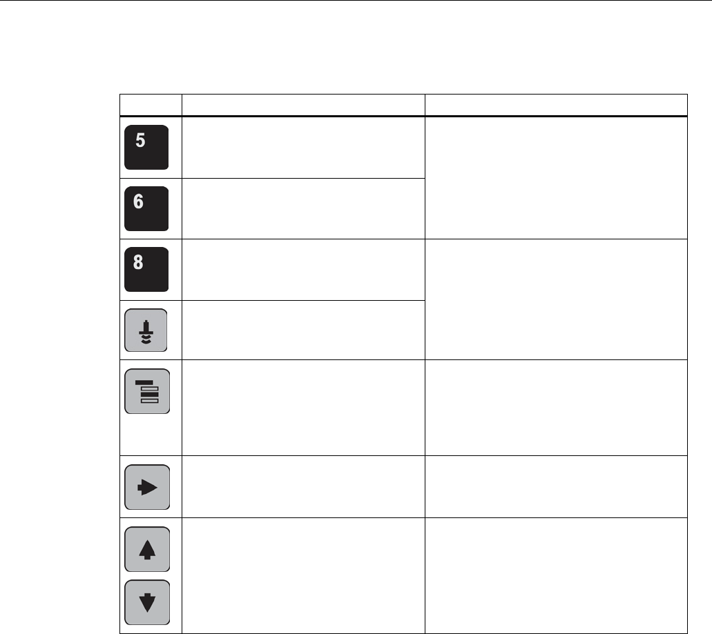
Commissioning
6.2 Operating via the handheld programmer
SITRANS LR250 (mA/HART)
58 Operating Instructions, 08/2014, A5E32220602-AC
Key functions in measurement mode
Key
Function
Result
Updates the loop current New value is displayed in LCD secondary
region.
Updates internal enclosure temperature
reading
Updates echo confidence value New value is displayed in LCD secondary
region.
Updates distance measurement
Mode
opens PROGRAM mode Opens the menu level last displayed in this
power cycle, unless power has been cycled
since exiting PROGRAM mode or more than
10 minutes have elapsed since PROGRAM
mode was used. Then top level menu will be
displayed.
RIGHT arrow
opens PROGRAM mode Opens the top level menu.
UP
or
DOWN arrow
toggles between
linear units and percent LCD displays measured value in either linear
units or percent.

Commissioning
6.2 Operating via the handheld programmer
SITRANS LR250 (mA/HART)
Operating Instructions, 08/2014, A5E32220602-AC 59
6.2.3
Programming
Note
•
While the device is in PROGRAM mode the output remains fixed and does not respond to
changes in the device.
•
The device automatically returns to Measurement mode after a period of inactivity in
PROGRAM mode (between 15 seconds and 10 minutes, depending on the menu level).
Change parameter settings and set operating conditions to suit your specific application. For
remote operation see Operating via SIMATIC PDM (Page 77) or Operating via AMS Device
Manager (Page 103).
Parameter menus
Note
For the complete list of parameters with instructions, see
Parameter Reference (Page 127).
Parameters are identified by name and organized into function groups. See LCD menu structure
(Page 293).
1. QUICK START
2. SETUP
2.1. DEV
ICE
............
2.7. LINEARIZATION
2.7.1. VOLUME
2.7.1.1. VESSEL SHAPE
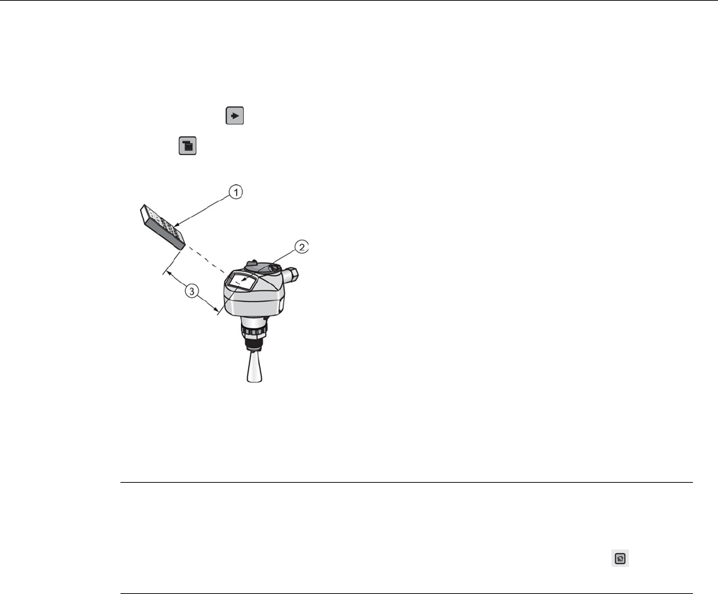
Commissioning
6.2 Operating via the handheld programmer
SITRANS LR250 (mA/HART)
60 Operating Instructions, 08/2014, A5E32220602-AC
1. Enter PROGRAM mode
● Point the programmer at the display from a maximum distance of 300 mm (1 ft).
●
RIGHT arrow
activates PROGRAM mode and opens menu level 1.
●
Mode
opens the menu level last displayed in PROGRAM mode within the last 10 minutes,
or menu level 1 if power has been cycled since then.
①
Handheld programmer
②
Display
③
Maximum distance: 300
mm (1 ft)
2. Navigating: key functions in Navigation mode
Note
•
In Navigation mode
ARROW
keys move to the next menu item in the direction of the
arrow.
•
For Quick Access to parameters via the handheld programmer, press Home , then
enter the menu number, for example:
2.7.1.
(Volume).
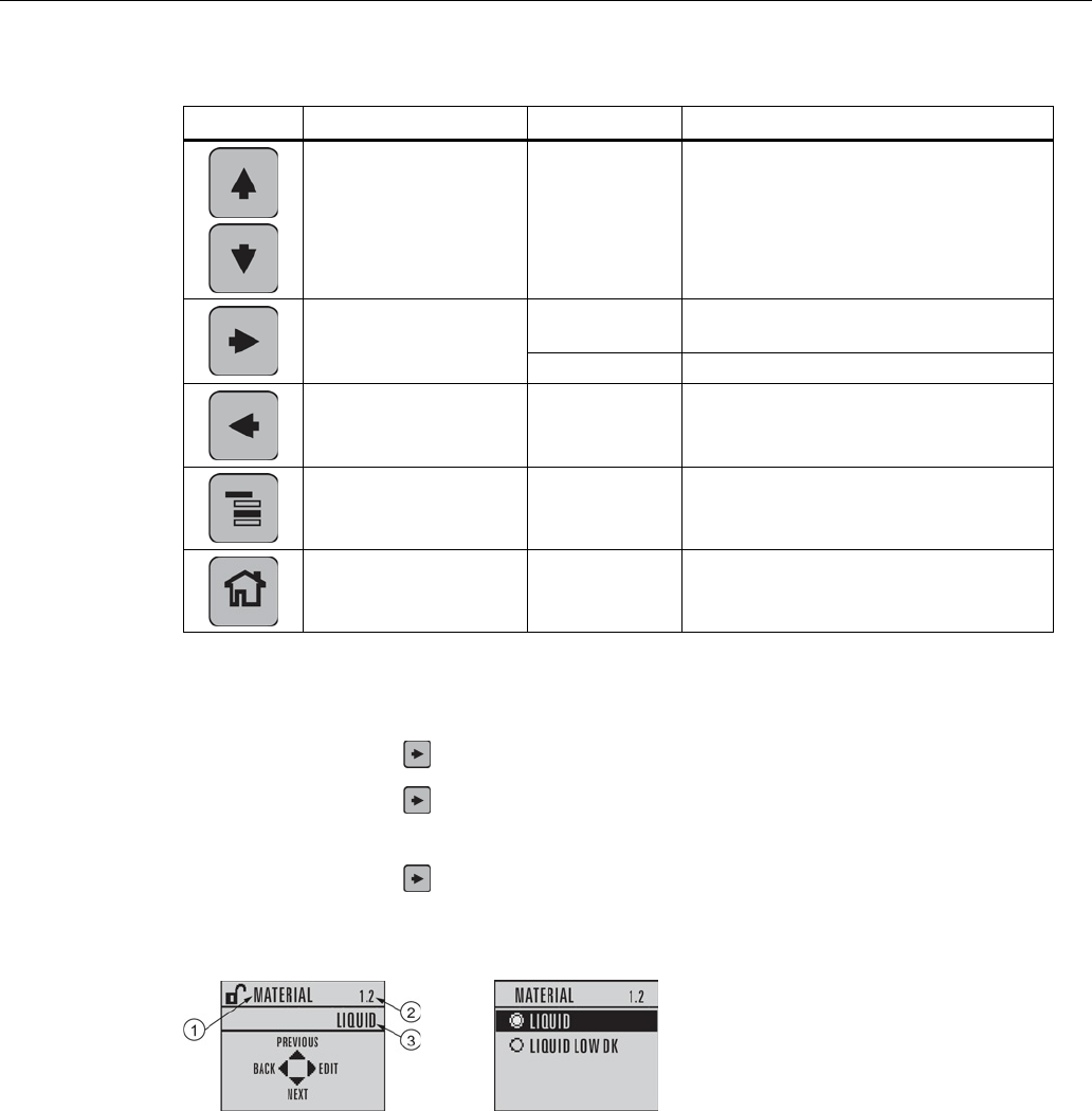
Commissioning
6.2 Operating via the handheld programmer
SITRANS LR250 (mA/HART)
Operating Instructions, 08/2014, A5E32220602-AC 61
Key
Name
Menu level
Function
UP
or
DOWN arrow
menu or
parameter Scroll to previous or next menu or
parameter
RIGHT arrow
menu Go to first parameter in the selected
menu, or open next menu.
parameter
Open Edit mode.
LEFT arrow
menu or
parameter Open parent menu.
Mode
menu or
parameter Change to
MEASUREMENT
mode.
Home
menu or
parameter Open top level menu: menu 1.
3. Editing in PROGRAM mode
● Navigate to the desired parameter.
● Press
RIGHT
arrow
to open parameter view.
● Press
RIGHT arrow
again to open
Edit
mode. The current selection is highlighted. Scroll
to a new selection.
● Press
RIGHT arrow
to accept it.
The LCD returns to parameter view and displays the new selection.
①
Parameter name
②
Parameter number
③
Current selection
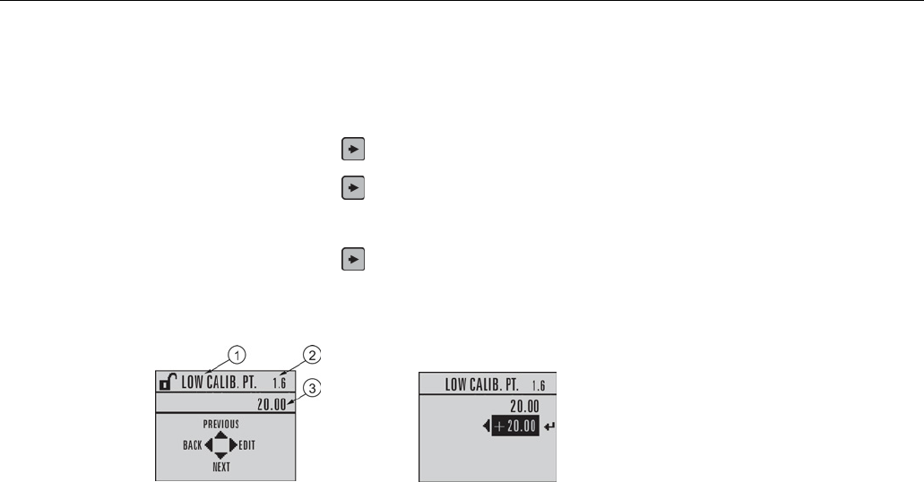
Commissioning
6.2 Operating via the handheld programmer
SITRANS LR250 (mA/HART)
62 Operating Instructions, 08/2014, A5E32220602-AC
4. Changing a numeric value
● Navigate to the desired parameter.
● Press
RIGHT arrow
to open parameter view. The current value is displayed.
● Press
RIGHT arrow
again to open
Edit
mode. The current value is highlighted.
● Key in a new value.
● Press
RIGHT arrow
to accept it.
The LCD returns to parameter view and displays the new selection.
①
Parameter name
②
Parameter number
③
Current selection
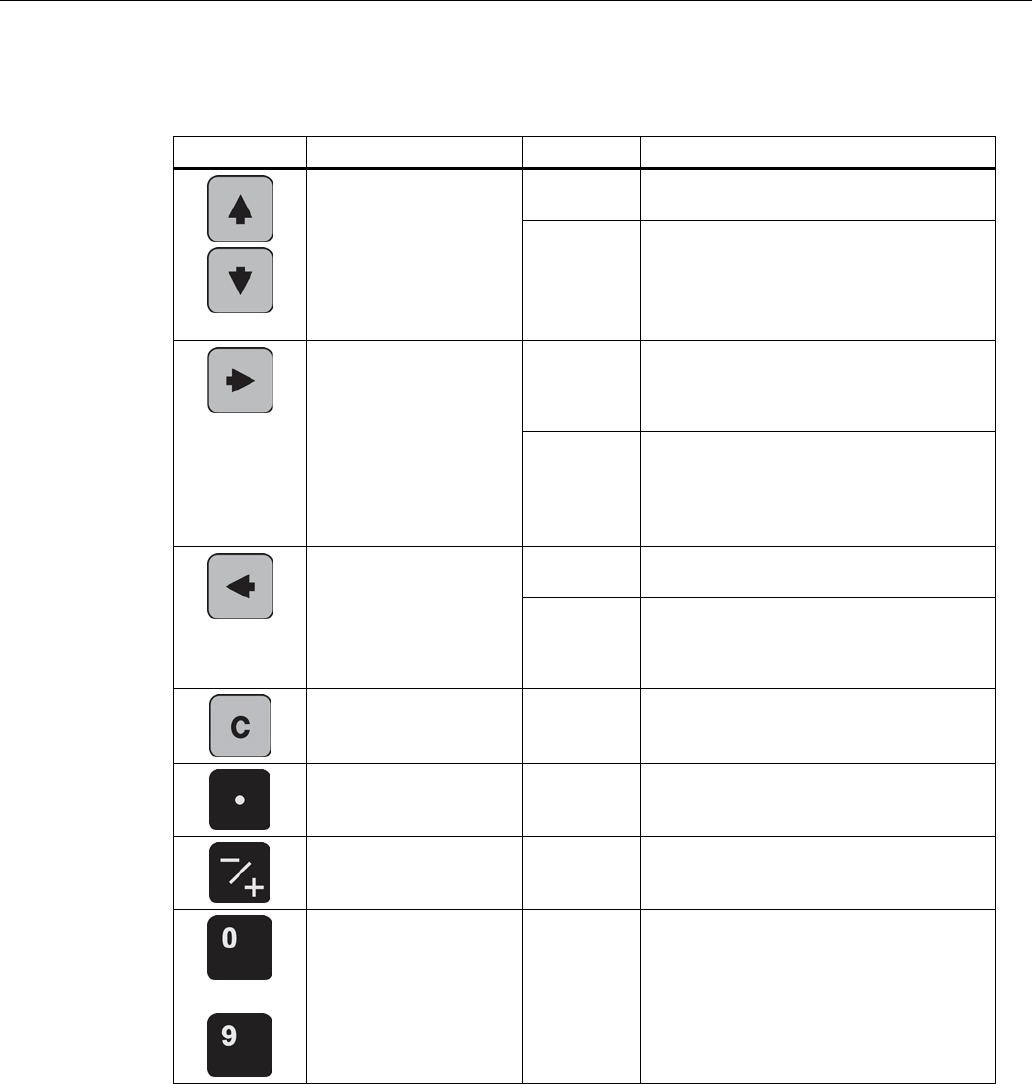
Commissioning
6.2 Operating via the handheld programmer
SITRANS LR250 (mA/HART)
Operating Instructions, 08/2014, A5E32220602-AC 63
Key functions in edit mode
Key
Name
Function
UP
or
DOWN arrow
Selecting
options
Scrolls to item.
Numeric
editing • Increments or decrements digits
• Toggles plus and minus sign
RIGHT arrow
Selecting
options • Accepts the data (writes the
parameter)
• Changes from
Edit
to
Navigation
mode
Numeric
editing • Moves cursor one space to the right
• or, with cursor on Enter sign, accepts
the data and changes from
Edit
to
Navigation
mode
LEFT arrow:
Selecting
options
Cancels
Edit
mode without changing the
parameter.
Numeric
editing • Moves cursor to plus/minus sign if this
is the first key pressed
• or moves cursor one space to the left
Clear
Numeric
editing Erases the display.
Decimal point
Numeric
editing Enters a decimal point.
Plus or minus sign
Numeric
editing Changes the sign of the entered value.
to
Numeral
Numeric
editing Enters the corresponding character.
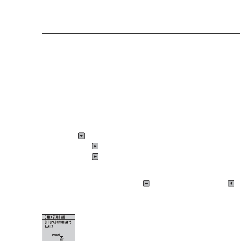
Commissioning
6.2 Operating via the handheld programmer
SITRANS LR250 (mA/HART)
64 Operating Instructions, 08/2014, A5E32220602-AC
6.2.3.1
Quick Start Wizard via the handheld programmer
Note
•
A reset to factory defaults should be performed before running the Quick Start Wizard if
the device has been used in a previous application. See
Master Reset (4.1.)
.
•
The Quick Start wizard settings are inter-related and changes apply only after you select
Finish
in the Wizard Complete step.
•
Do not use the Quick Start wizard to modify parameters: see instead Parameter
Reference (Page 127). (Perform customization for your application only after the Quick
Start has been completed).
•
Default settings in the parameter tables are indicated with an asterisk (*).
1. Quick Start
1.1. Quick Start Wiz
● Point the programmer at the display from a maximum distance of 300 mm (1 ft), then press
RIGHT arrow
to activate PROGRAM mode and open menu level 1.
● Press
RIGHT arrow
twice to navigate to menu item 1.1 and open parameter view.
● Press
RIGHT arrow
to open Edit mode or DOWN arrow to accept default values and
move directly to the next item.
● To change a setting, scroll to the desired item or key in a new value.
● After modifying a value, press
RIGHT arrow
to accept it and press
DOWN arrow
to
move to the next item.
● Quick Start settings take effect only after you select
Finish.
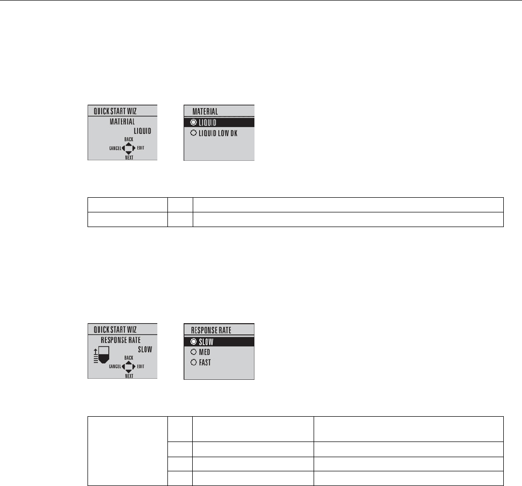
Commissioning
6.2 Operating via the handheld programmer
SITRANS LR250 (mA/HART)
Operating Instructions, 08/2014, A5E32220602-AC 65
Material
Selects the appropriate echo processing algorithms for the material [see
Position Detect
(2.8.4.2.)
for more detail].
Options
*
LIQUID
LIQUID LOW DK
a)
(low dielectric liquid – CLEF algorithm enabled)
a) dK < 3.0
Response Rate
Sets the reaction speed of the device to measurement changes in the target range. Use a
setting just faster than the maximum filling or emptying rate (whichever is greater).
Options
Response Rate (1.3.)
Fill rate per Minute (2.4.2.)/Empty rate per
Minute (2.4.3.)
*
SLOW
0.1 m/min (0.32 ft/min)
MED
1.0 m/min (3.28 ft/min)
FAST
10.0 m/min (32.8 ft/min)
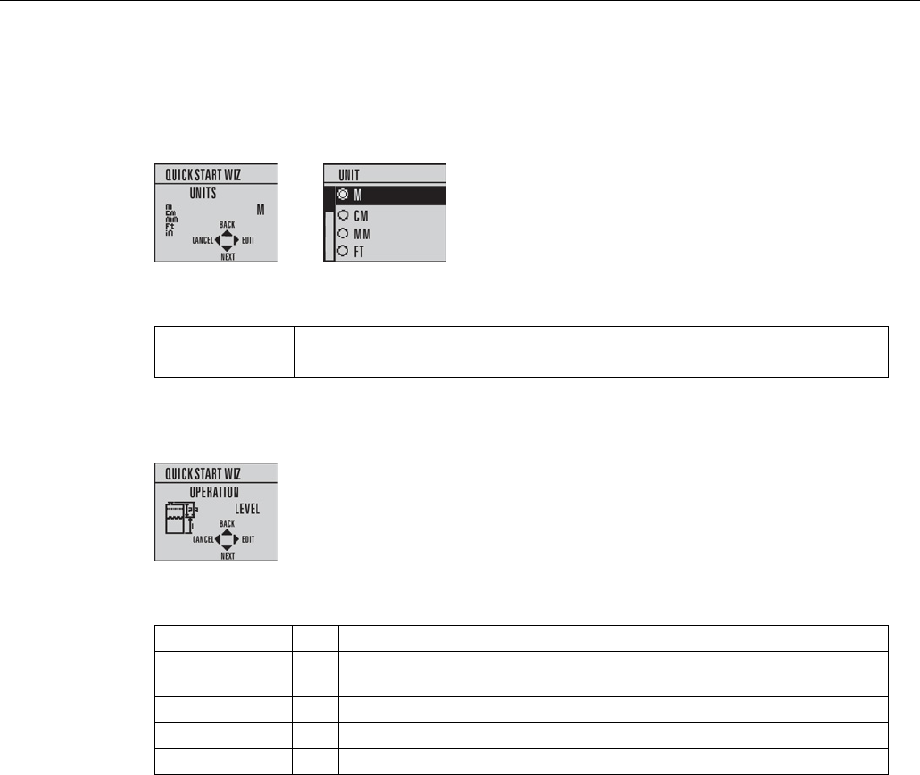
Commissioning
6.2 Operating via the handheld programmer
SITRANS LR250 (mA/HART)
66 Operating Instructions, 08/2014, A5E32220602-AC
Units
Sensor measurement units.
Options
m, cm, mm, ft, in.
Default: m
Operation
Operation
Description
NO SERVICE Measurement and associated loop current are not updated, and the device
defaults to Fail-safe mode
a)
.
LEVEL
*
Distance to material surface referenced from Low Calibration Point
SPACE
Distance to material surface referenced from High Calibration Point
DISTANCE
Distance to material surface referenced from Sensor reference point
a) See Material Level (2.5.1.) for more detail.
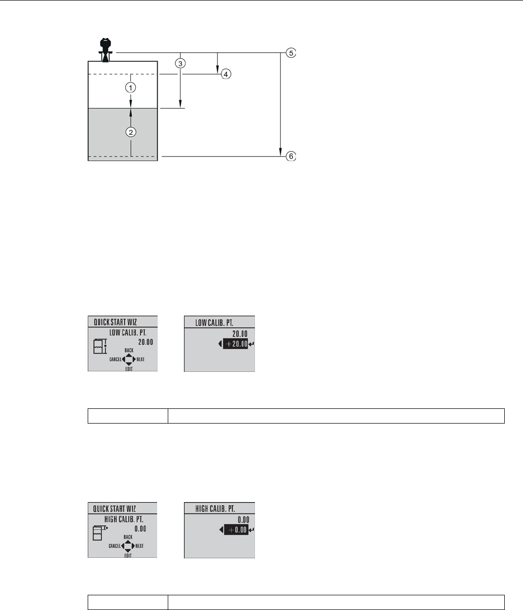
Commissioning
6.2 Operating via the handheld programmer
SITRANS LR250 (mA/HART)
Operating Instructions, 08/2014, A5E32220602-AC 67
①
Space
④
High Calibration Point (process full level)
②
Level
⑤
Sensor reference point
a)
③
Distance
⑥
Low Calibration Point (process empty level)
a) The point from which High and Low Calibration points are referenced: see
Dimension
drawings
.
Low Calibration Point
Distance from Sensor Reference to Low Calibration Point: usually process empty level. (See
Operation
for an illustration.)
Values
Range: 0.00 to 20.00 m
High Calibration Point
Distance from Sensor reference point to High Calibration Point: usually process full level. (See
Operation
for an illustration.)
Values
Range: 0.00 to 20.00 m

Commissioning
6.2 Operating via the handheld programmer
SITRANS LR250 (mA/HART)
68 Operating Instructions, 08/2014, A5E32220602-AC
Wizard complete
Options
BACK, CANCEL, FINISH (Display returns to 1.1 Quick Start Wiz menu when
Quick Start is successfully completed.)
Press
DOWN arrow (Finish).
Then press
LEFT arrow
to return to
Measurement
mode.
SITRANS LR250 is now ready to operate.
6.2.3.2
Auto False Echo Suppression
If you have a vessel with known obstructions, we recommend using Auto False Echo
Suppression to prevent false echo detection. See
TVT setup (2.8.7.)
for instructions
.
This feature can also be used if the display shows a false high level, or the reading is fluctuating
between the correct level and a false high level.
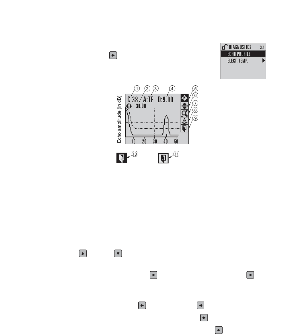
Commissioning
6.2 Operating via the handheld programmer
SITRANS LR250 (mA/HART)
Operating Instructions, 08/2014, A5E32220602-AC 69
6.2.3.3
Requesting an Echo Profile
•
In
PROGRAM
mode, navigate to:
Level Meter > 3. > 3.1
.
•
Press
RIGHT arrow
to request a profile.
①
Confidence
⑦
Zoom
②
Distance from Low Calibration Point to vertical cross
-hair
⑧
Mea
sure
③
Algorithm: tF
(trueFirst)
⑨
Exit
④
Distance from flange face to target
⑩
Exit icon selected
⑤
Pan left/right
- selected
⑪
Exit icon deselected
⑥
Pan up/down
● Use
UP
or
DOWN arrow
to scroll to an icon. When an icon is highlighted, that feature
becomes active.
● To move a cross-hair, press
RIGHT arrow
to increase the value,
LEFT arrow
to
decrease.
● To Zoom into an area, position the intersection of the cross-hairs at the center of that area,
select
Zoom
, and press
RIGHT arrow.
Press
LEFT arrow
to Zoom out.
● To update the profile, select
Measure
and press
RIGHT arrow.
● To return to the previous menu, select
Exit
then press
RIGHT arrow.

Commissioning
6.3 Application examples
SITRANS LR250 (mA/HART)
70 Operating Instructions, 08/2014, A5E32220602-AC
6.3
Application examples
Note
In the a
pplications illustrated below, values are for example purposes only.
You can use these examples as setup references. Enter the values in the parameter tables to
select the corresponding functions.
Configure the basic settings using the Quick Start wizard parameters. (These parameters are
inter-related, and changes take effect only after you select
FINISH
to apply changes in the final
step.)
In each example, after performing a Quick Start, navigate to the other required parameters either
via the handheld programmer, or using a Device Management tool (SIMATIC PDM or AMS
Device Manager) and enter the appropriate values.
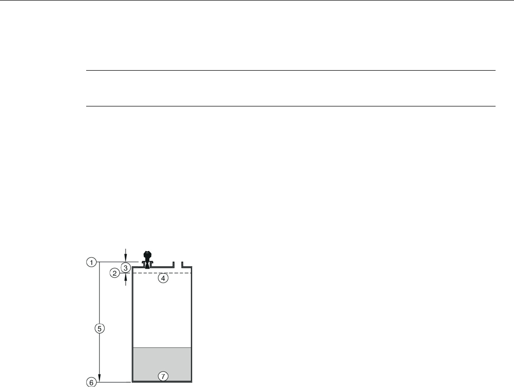
Commissioning
6.3 Application examples
SITRANS LR250 (mA/HART)
Operating Instructions, 08/2014, A5E32220602-AC 71
6.3.1
Liquid resin in storage vessel, level measurement
Note
Minimum distance from flange face to target is limited by Near Range (2.8.1.)
.
To obtain level measurement/4 to 20 mA output proportional to resin levels:
● Low Calibration Pt. = 5 m (16.5 ft) from sensor reference point
● High Calibration Pt.= 0.5 m (1.64 ft) from sensor reference point
● Max.fill/empty rate = 0.2 m/min (0.65 ft/min)
In the event of a loss of echo:
● SITRANS LR250 is to go into Fail-safe High after 2 minutes.
①
Sensor reference point
⑤
5 m
②
High calibration point
⑥
Low calibration point
③
0.5 m
⑦
0% level
④
100% level
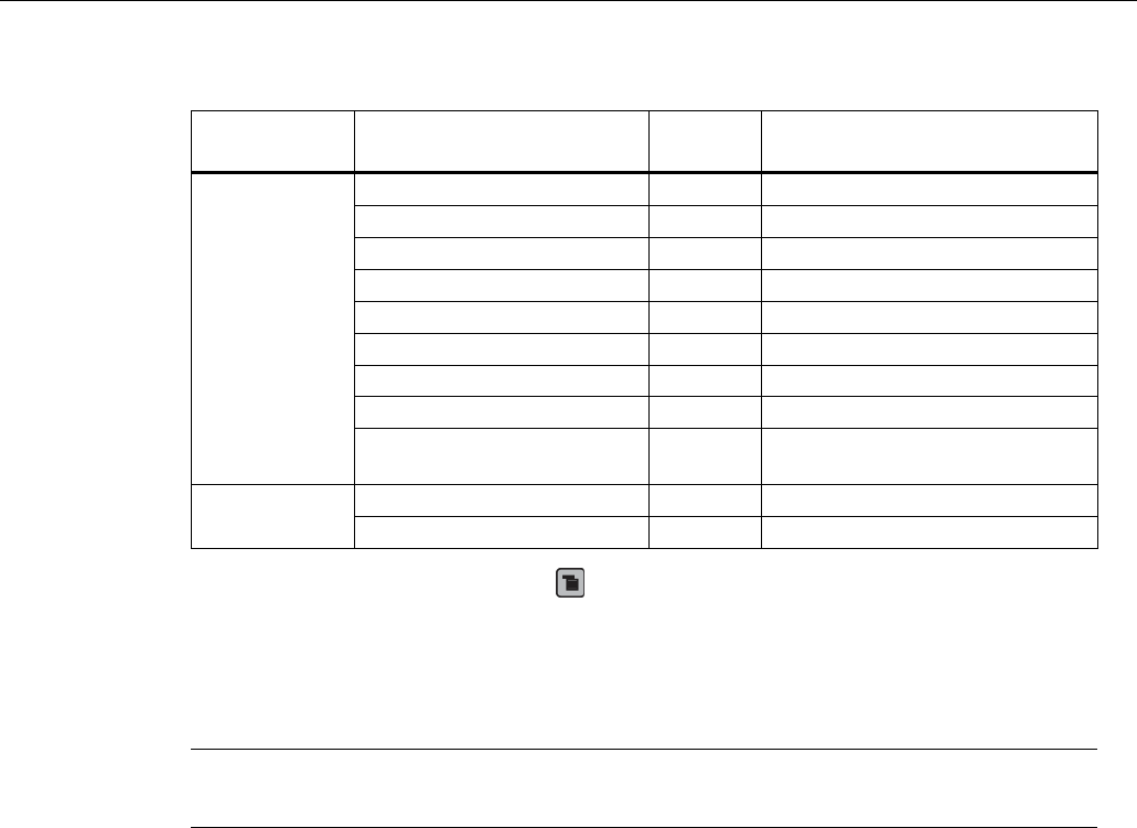
Commissioning
6.3 Application examples
SITRANS LR250 (mA/HART)
72 Operating Instructions, 08/2014, A5E32220602-AC
Parameter type
Parameter No. /Name
Options/
Values
Function
Quick Start
Wizard
parameters
Introduction
NEXT
Continue with Wizard.
Language
NEXT
Continue with current language.
Material
LIQUID
Response Rate
MED
Medium =1 m/minute
Units
M
meters
Operation
LEVEL
Level
Low Calibration Point
5
5 m (16.5 ft)
High Calibration Point
0.5
0.5 m (1.64 ft)
Wizard Complete
FINISH
Transfers Quick Start settings to
device.
Independent
parameters
LOE Timer (2.5.2.)
2
2 minutes
Material Level (2.5.1.)
HI
Fail-safe level set to High
Return to
Measurement
: press
Mode
to start normal operation.
6.3.2
Horizontal vessel with volume measurement
Note
The minimum distance from the flange face to the target is limited by Near Range (2.8.1.)
.
To obtain level measurement/4 to 20 mA output proportional to vessel volume in a chemical
vessel:
● Low Calibration Point = 3.5 m (11.48 ft) from sensor reference point
● High Calibration Point = 0.5 m (1.64 ft) from sensor reference point
● Max. fill/empty rate = 0.2 m/min (0.65 ft/min)
Select vessel shape, Parabolic Ends, and enter values for A and L, to obtain a volume reading
instead of level.
In the event of a loss of echo: SITRANS LR250 is to go into Fail-safe High after 2 minutes.
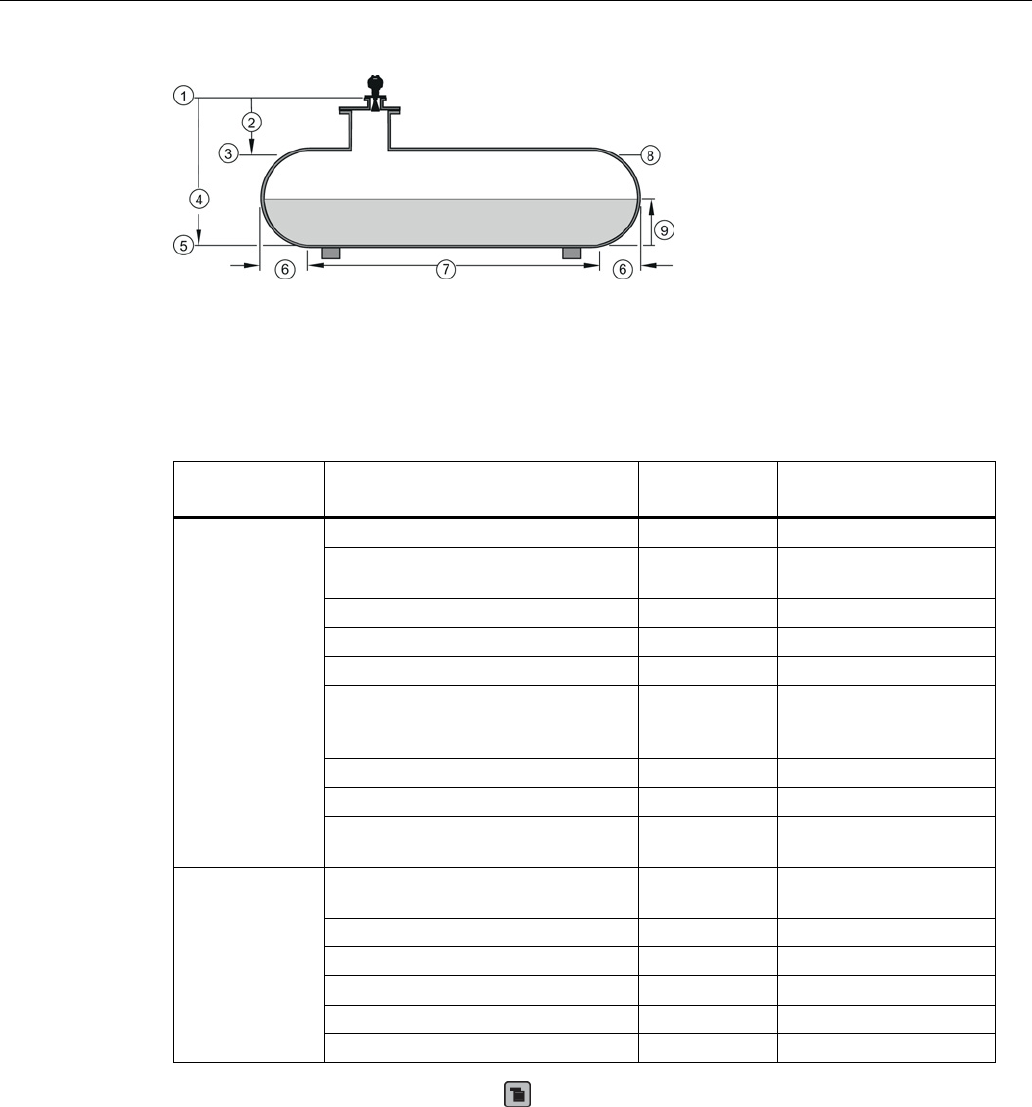
Commissioning
6.3 Application examples
SITRANS LR250 (mA/HART)
Operating Instructions, 08/2014, A5E32220602-AC 73
①
Sensor reference point
⑥
A = 0.8 m
②
0.5 m
⑦
L = 6 m
③
High Calibration Point
⑧
100% = 8000 L
④
3.5. m
⑨
Volume reading
⑤
Low Calibration Point
Parameter type
Parameter No./Name
Options/
Values
Function
Quick Start
Wizard
parameters
Introduction
NEXT
Continue with Wizard.
Language
NEXT
Continue with current
language.
Material
LIQUID
Response Rate
MED
Medium =1 m/minute
Units
M
meters
Operation
LEVEL
Level is reported as
Volume when a vessel
shape is selected.
Low Calibration Point
3.5
3.5 m (11.48 ft)
High Calibration Point
0.5
0.5 m (1.64 ft)
Wizard Complete
FINISH
Transfers Quick Start
settings to device.
Independent
parameters
Vessel Shape (2.7.1.1.)
PARABOLIC
ENDS
Defines vessel shape.
Maximum Volume (2.7.1.2.)
8000
8000 liters
Vessel Dimension A (2.7.1.3.)
0.8
0.8 m (2.62 ft)
Vessel Dimension L (2.7.1.4.)
6
6 m (19.68 ft)
LOE Timer (2.5.2.)
2
2 minutes
Material Level (2.5.1.)
HI
Fail-safe level set to High
Return to
Measurement:
press
Mode
to start normal operation.
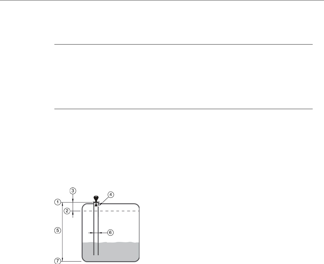
Commissioning
6.3 Application examples
SITRANS LR250 (mA/HART)
74 Operating Instructions, 08/2014, A5E32220602-AC
6.3.3
Application with stillpipe
Note
•
Near Range (2.8.1.)
(Blanking) will be set at the factory. Check the process connection
tag for specific values.
•
Suitable pipe diameters are 40 mm (1.5") to 100 mm (4").
•
The pipe diameter must be matched with the antenna size. Use the largest antenna size
that will fit the stillpipe/bypass pipe. See Dimensions (Page 209).
•
See Mounting on a Stillpipe or Bypass Pipe (Page 32) for installation guidelines.
This application is to obtain a level measurement and corresponding 4 to 20 mA output
proportional to the oil level in a fuel storage vessel.
● Low Calibration Pt. is 5 m (16.5 ft) from the sensor reference point.
● High Calibration Pt. is 0.5 m (1.65 ft) from the sensor reference point.
● The stillpipe inside diameter is 50 mm (1.96").
● The maximum rate of filling or emptying is about 0.1 m (4")/min.
①
sensor reference point
⑤
5 m
②
high calibration point
⑥
50 mm I.D.
③
0.5 m
⑦
low calibration point
④
vent hole

Commissioning
6.3 Application examples
SITRANS LR250 (mA/HART)
Operating Instructions, 08/2014, A5E32220602-AC 75
Parameter type
Parameter No./Name
Options/Values
Function
Quick Start Wizard
Introduction
NEXT
Continue with Wizard.
Language
NEXT
Continue with current
language.
Material
LIQUID LOW DK
Response Rate
MED
Medium =1 m/minute
Units
M
meters
Operation
LEVEL
Level is reported as
Volume when a vessel
shape is selected.
Low Calibration Point
5
5 m (16.5 ft)
High Calibration Point
0.5
0.5 m (1.64 ft)
Wizard Complete
FINISH
Transfers Quick Start
settings to device.
Independent
parameters
Propagation Factor
(2.8.3.)
a)
0.988
P.F. for a 50 mm
(1.96") I.D. stillpipe
Position Detect
(2.8.4.2.)
HYBRID
CLEF Range
(2.8.4.4.)
a)
4.3 Low calibration point -
0.7 m = 4.3 m (14.1 ft)
a)
The recommended values for the propagation factor and for CLEF range are dependent on the
stillpipe diameter. Refer to the next table for values.
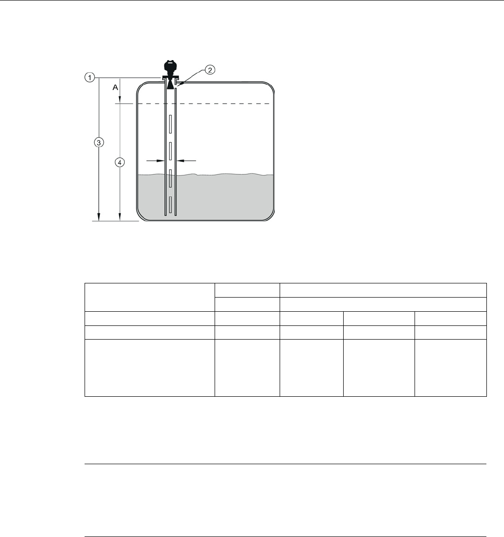
Commissioning
6.3 Application examples
SITRANS LR250 (mA/HART)
76 Operating Instructions, 08/2014, A5E32220602-AC
Propagation Factor/Stillpipe Diameter
①
sensor reference point
③
low calibration point
②
air gap
④
CLEF range 2.8.4.4.
A
700 or 1000 mm (see CLEF Range settings in table below)
Values
Range
0.3 to 1.0 depending on pipe size
Default
1.0000
Nominal Pipe Size
a)
40 mm (1.5")
50 mm (2")
80 mm (3")
100 mm (4")
Propagation Factor
0.9844
0.988
0.9935
0.9965
CLEF Range (2.8.4.4.) settings
Low
calibration
point -
700 mm
(2.29 ft)
b)
Low
calibration
point -
700 mm
(2.29 ft)
b)
Low calibration
point -1000 mm
(3.28 ft)b)
Low calibration
point -1000 mm
(3.28 ft)b)
a)
Since pipe dimensions may vary slightly, the propagation factor may also vary.
b)
CLEF range covers the whole measurement range except first 700 or 1000 mm from sensor
reference point
Note
Flanged and Hygienic encapsulated antenna
For Flanged encapsulated antenna (7ML5432) and Hygienic encapsulated antenna
(7ML5433 ) match the process connection size to the pipe diameter. For example, DN80/3"
flange to DN80/3" pipe.

SITRANS LR250 (mA/HART)
Operating Instructions, 08/2014, A5E32220602-AC 77
Remote operation
7
7.1
Operating via SIMATIC PDM
SIMATIC PDM is a software package used to commission and maintain process devices. Please
consult the operating instructions or online help for details on using SIMATIC PDM. You can find
more information on versions and compatibility at our website:
SIMATIC PDM (www.siemens.com/simatic-pdm).
7.1.1
Functions in SIMATIC PDM
Note
•
For a complete list of parameters, see Parameter Reference (Page 127).
•
While the device is in
PROGRAM
mode the output remains fixed and does not respond to
changes in the device.
7.1.1.1
PDM function overview
SIMATIC PDM monitors the process values, alarms and status signals of the device. It allows
you to display, compare, adjust, verify, and simulate process device data; also to set schedules
for calibration and maintenance.
Parameters are identified by name and organized into function groups. See LCD menu structure
(Page 293) for a chart and Changing parameter settings using SIMATIC PDM (Page 86) for
more details. The menu structure for SIMATIC PDM is almost identical to that for the LCD.
See Parameters accessed via pull-down menus (Page 87) for parameters that do not appear in
the menu structure in SIMATIC PDM.

Remote operation
7.1 Operating via SIMATIC PDM
SITRANS LR250 (mA/HART)
78 Operating Instructions, 08/2014, A5E32220602-AC
7.1.1.2
Features of SIMATIC PDM Rev. 6.0, SP4 or higher
The graphic interface in the device makes monitoring and adjustments easy.
Feature
Function
Quick Start (Page 81)
Device configuration for simple applications
Echo Profile Utilities (Page 88)
Easy access to echo profile viewing/comparison, TVT shaping,
auto false echo suppression and echo setup
Auto False Echo Suppression
(Page 92)
Screen out false echoes
TVT Shaper (Page 91)
Manual TVT adjustment
Process Variables (Page 99)
Monitor process variables and level trend
Security (Page 102)
Protect security and communication parameters from
modification by the maintenance user
7.1.1.3
Features of SIMATIC PDM Rev. 5.2, SP1
SIMATIC PDM Rev. 5.2 SP1 is supported only for basic configuration and troubleshooting. For
advanced features such as the Quick Start wizard, Rev. 6.0 SP3 HF2 or higher is required.
7.1.1.4
SIMATIC PDM Version
Check the support page of our website to make sure you have the latest version of SIMATIC
PDM, the most recent Service Pack (SP) and the most recent hot fix (HF): SIMATIC PDM
Version (https://support.automation.siemens.com). Browse to
Product Information > Automation
Technology > Process control systems > SIMATIC PCS 7 > System components > SIMATIC
PDM.
7.1.2
Initial setup
To ensure that SIMATIC PDM connects properly, complete the following two processes:
1. De-activate buffers
2. Update the Electronic Device Description (EDD)
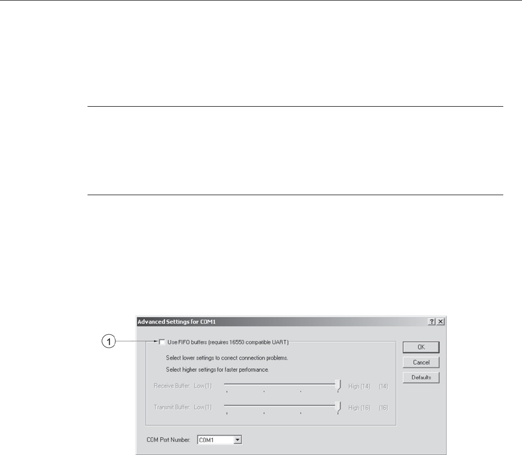
Remote operation
7.1 Operating via SIMATIC PDM
SITRANS LR250 (mA/HART)
Operating Instructions, 08/2014, A5E32220602-AC 79
7.1.2.1
Deactivating buffers
This deactivation is required to align SIMATIC PDM with the HART modem for Windows 2000®
and Windows® XP operating Systems. Windows® is a registered trademark of the Microsoft
Corporation.
Note
•
This deactivation is only necessary when you're connecting via RS232 (COM1) as
opposed to USB.
•
You will need administrative rights on your operating system to deactivate buffers.
•
SIMATIC PDM operates only in the Windows XP Professional version, not in the Home
version.
1. Click
Start/Settings/Control Panel
to begin configuration.
2. Double click
System
, select the
Hardware
tab, and click the
Device Manager
button.
3. Open
Ports
folder and double click the COM Port used by the system to open the
Communications Port Properties
window.
4. Select the
Port Settings
tab and double click the
Advanced
button.
5. If the
Use FIFO buffers
radio box is selected, click to deselect.
①
Deselect Use FIFO buffers radio box
6. Click
OK
to close out. Close all screens and then reboot.

Remote operation
7.1 Operating via SIMATIC PDM
SITRANS LR250 (mA/HART)
80 Operating Instructions, 08/2014, A5E32220602-AC
7.1.3
Updating the Electronic Device Description (EDD)
You can locate the EDD in Device Catalog, under
Sensors/Level/Echo/SiemensMilltronics/SITRANS LR250
. The EDD revision must match the
Firmware revision in the device.
To install a new EDD:
1. Download the most current EDD from our website: Product page
(http://www.siemens.com/LR250)
2. Save files to your computer, and extract the zipped file to an easily accessed location.
3. Launch
SIMATIC PDM – Manage Device Catalog
, browse to the unzipped EDD file and
select it.
7.1.3.1
Configuring a new device
Note
•
Clicking on
Cancel
during an upload from device to SIMATIC PDM will result in some
parameters being updated.
•
Application Guides for setting up HART devices with SIMATIC PDM can be downloaded
from our website:
Product page (http://www.siemens.com/LR250).
1. Check that you have the most recent EDD, and if necessary update it. [See Updating the
Electronic Device Description (EDD) (Page 80) above].
2. Launch SIMATIC Manager and create a new project for the device.
3. Open the menu
Device – Master Reset
and click on
OK
to perform a reset to Factory
Defaults.
4. After the reset is complete upload parameters to the PC/PG.
5. Configure the device via the Quick Start wizard.
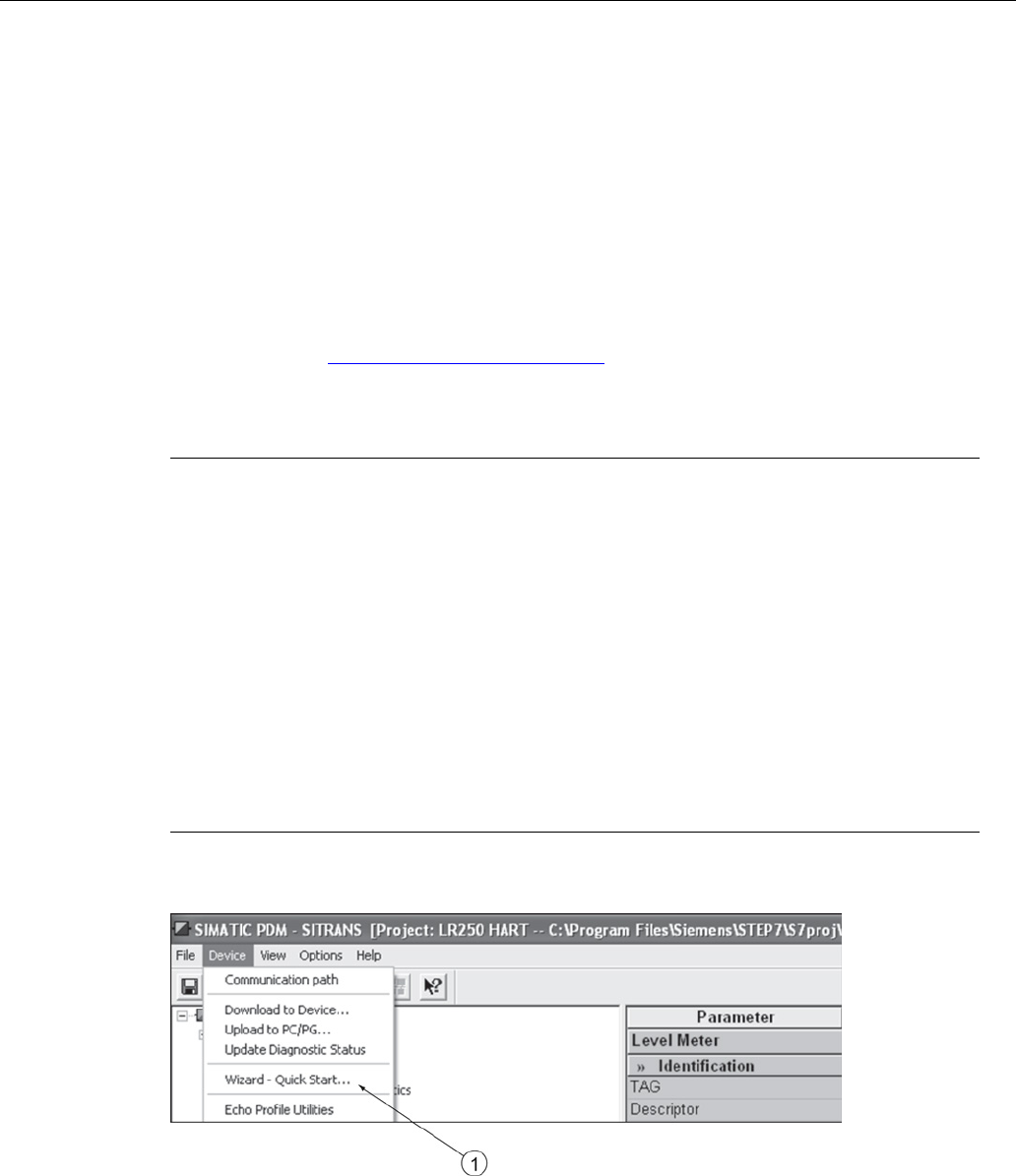
Remote operation
7.1 Operating via SIMATIC PDM
SITRANS LR250 (mA/HART)
Operating Instructions, 08/2014, A5E32220602-AC 81
7.1.4
Quick Start Wizard via SIMATIC PDM
The graphic Quick Start Wizard provides an easy step-by-step procedure that configures the
device for a simple application.
Please consult the operating instructions or online help for details on using SIMATIC PDM.
1. If you have not already done so, check that you have the most up-to-date Electronic Device
Description (EDD) for your device. [See Configuring a new device (Page 80).]
2. Launch SIMATIC Manager and create a new project. Application Guides for setting up HART
and PROFIBUS PA devices with SIMATIC PDM can be downloaded from the product page of
our website:
Product page (http://www.siemens.com/LR250)
Quick start
Note
•
A reset to
Factory Defaults
should be performed before running the Quick Start Wizard if
device has been used in a previous application. See Master Reset via SIMATIC PDM
(Page 98).
•
The Quick Start wizard settings are inter-related and changes apply only after you click
on
FINISH AND DOWNLOAD
at the end of the last step to save settings offline and
transfer them to the device.
•
Do not use the Quick Start Wizard to modify individual parameters: for quick access to
echo profile parameters, see Echo Profile via SIMATIC PDM (Page 89) or see
Parameter
Reference (Page 127) for a complete list. (Perform customization only after the Quick
Start has been completed.)
•
Click on
BACK
to return and revise settings or
CANCEL
to exit the Quick Start.
•
For a vessel with obstructions see Auto False Echo Suppression via SIMATIC PDM
(Page 92).
Launch SIMATIC PDM, open the menu
Device – Wizard - Quick Start
, and follow steps 1 to 5.
①
Quick Start
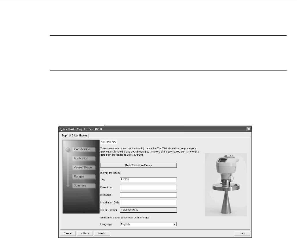
Remote operation
7.1 Operating via SIMATIC PDM
SITRANS LR250 (mA/HART)
82 Operating Instructions, 08/2014, A5E32220602-AC
Step 1 – Identification
Note
•
The layout of the dialog boxes shown may vary according to the resolution setting for
your computer monitor.
•
SITRANS PDM limits the TAG field to a maximum of 24 characters.
1. Click on
Read Data from Device
to upload Quick Start parameter settings from the device to
the PC/PG and ensure PDM is synchronized with the device.
2. If required, change the language for the local user interface.
3. Click on
NEXT
to accept the default values. (Description, Message, and Installation Date
fields can be left blank.)
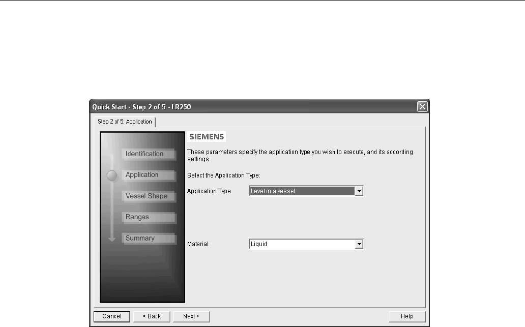
Remote operation
7.1 Operating via SIMATIC PDM
SITRANS LR250 (mA/HART)
Operating Instructions, 08/2014, A5E32220602-AC 83
Step 2 – Application
Select the application type (level or volume) and the material, then click on
NEXT
.
See Application with Stillpipe (Page 74) for a Low Dielectric Liquid application.
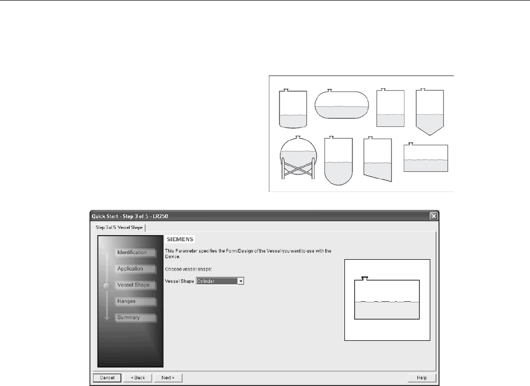
Remote operation
7.1 Operating via SIMATIC PDM
SITRANS LR250 (mA/HART)
84 Operating Instructions, 08/2014, A5E32220602-AC
Step 3 – Vessel Shape
The vessel shapes shown are
predefined.
For a vessel with obstructions, see
Auto False Echo Suppr
ession via
SIMATIC PDM
(Page 92).
Select the vessel shape, and click on
NEXT
.
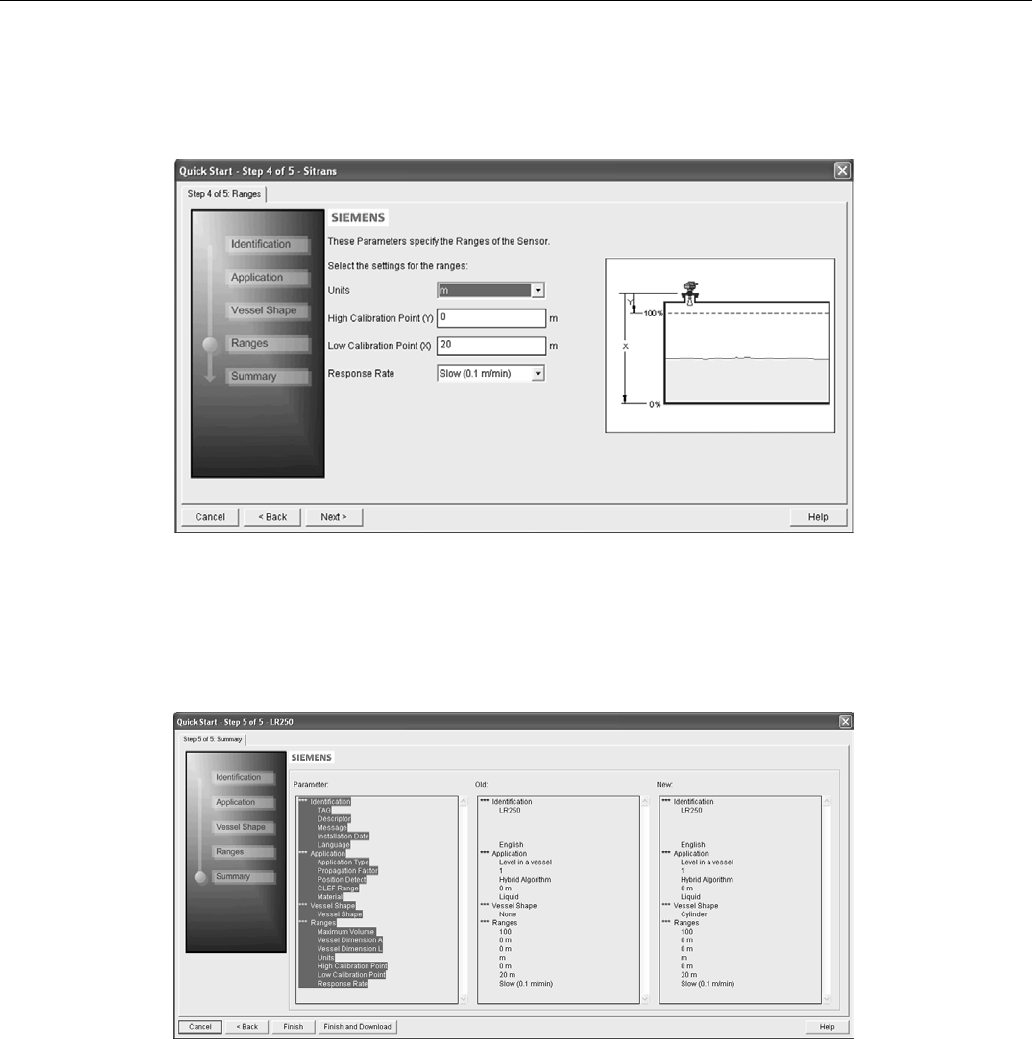
Remote operation
7.1 Operating via SIMATIC PDM
SITRANS LR250 (mA/HART)
Operating Instructions, 08/2014, A5E32220602-AC 85
Step 4 – Ranges
Set the parameters, and click on
NEXT
.
Step 5 – Summary
Check parameter settings, and click on
BACK
to return and revise values,
FINISH
to save
settings offline, or
FINISH AND DOWNLOAD
to save settings offline and transfer them to the
device.
The message
Quick Start was successful
will appear. Click on
OK
.
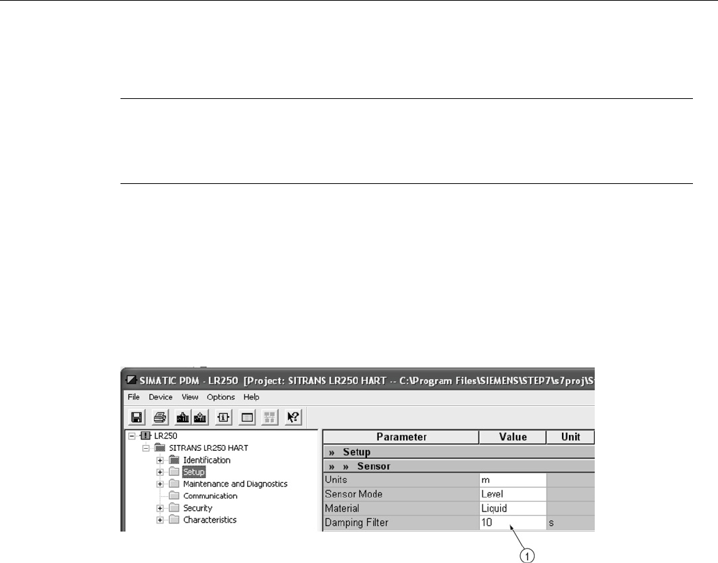
Remote operation
7.1 Operating via SIMATIC PDM
SITRANS LR250 (mA/HART)
86 Operating Instructions, 08/2014, A5E32220602-AC
7.1.5
Changing parameter settings using SIMATIC PDM
Note
•
For a complete list of parameters, see Parameter Reference (Page 127).
•
Clicking on
Cancel
during an upload from device to SIMATIC PDM will result in some
parameters being updated.
Many parameters are accessed via pull-down menus in PDM. See Parameters accessed via
pull-down menus (Page 87) for others.
1. Launch SIMATIC PDM, connect to device, and upload data from device.
2. Adjust parameter values in the parameter value field then
Enter
. The status fields read
Changed
.
3. Open the Device menu, click on
Download to device
, then use
File - Save
to save settings
offline. The status fields are cleared.
①
Value fields
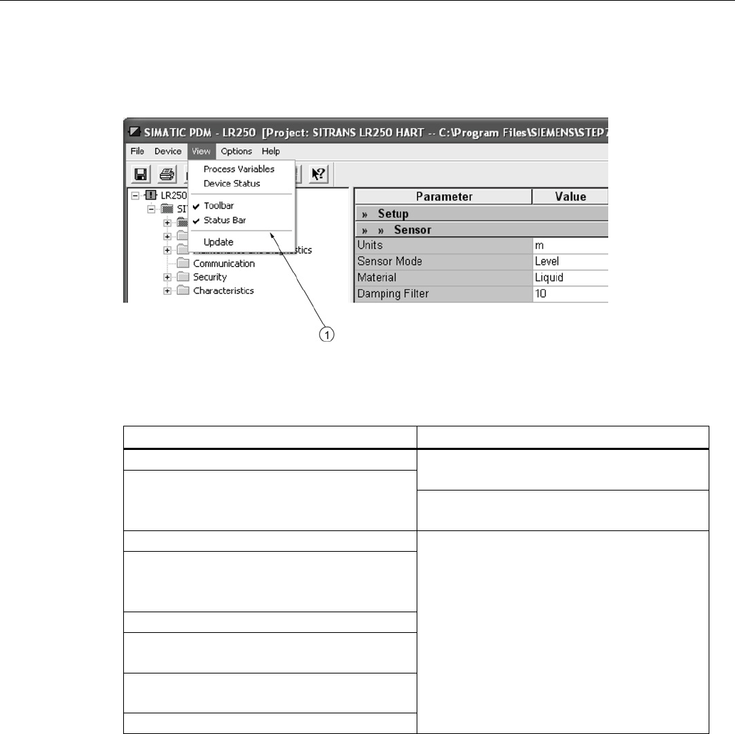
Remote operation
7.1 Operating via SIMATIC PDM
SITRANS LR250 (mA/HART)
Operating Instructions, 08/2014, A5E32220602-AC 87
7.1.6
Parameters accessed via pull-down menus
Click on
Device
or
View
to open the associated pull-down menus.
①
pull-down menus
Pull-down menus
Device menus
View menus
Communication path
Process Variables (Page 99)
Device Status (Page 101)
Download to device
Upload to PC/PG
Update Diagnostic Status
Toolbar
Status bar
Wizard - Quick Start (Page 81)
Update
Echo Profile Utilities (Page 88)
Maintenance (Page 95)
Wear (Page 98)
Select Analog Output (Page 97)
Self Test (Page 97)
Loop Test (Page 97)
Configuration Flag Reset (Page 97)
Master Reset (Page 98)
HART Communication (Page 98)

Remote operation
7.1 Operating via SIMATIC PDM
SITRANS LR250 (mA/HART)
88 Operating Instructions, 08/2014, A5E32220602-AC
7.1.6.1
Echo profile utilities
Open the menu
Device – Echo Profile Utilities
and click on the appropriate tab for easy access
to:
● Echo profile (Page 89)
● View Saved Echo Profiles (Page 90)
● TVT Shaper (Page 91)
● Auto False Echo Suppression (Page 92)
● Echo Setup (Page 95)
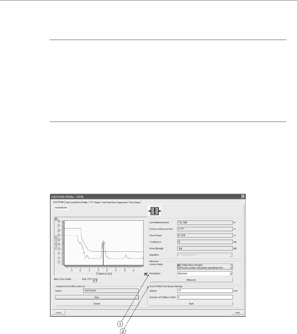
Remote operation
7.1 Operating via SIMATIC PDM
SITRANS LR250 (mA/HART)
Operating Instructions, 08/2014, A5E32220602-AC 89
7.1.6.2
Echo profile
Note
•
Double click on each axis to see the Xscale and Data Scale values.
•
To zoom in to a section of the profile, left-click and drag a marquee around it. Right click
inside the window to zoom out.
•
Expand or compress the x and/or y axes:
– Left-click on the axis and drag in either direction to reposition the low end of the scale.
– Right-click on the axis and drag in either direction to reposition the high end of the
scale.
•
After saving a profile click on
OK
, not the
x
button, to close the Echo Profile Utilities
window, otherwise the profile will not be saved.
● In the
Echo Profile Utilities
window click the
Echo Profile
tab.
● Initial profile graph is blank upon entry to dialog. Click
Measure
to update the profile.
● It is recommended to use the
Detailed
resolution view of the echo profile for troubleshooting.
For faster and more coarse views, the
Standard
resolution may be used.
● Click
Save
and in the new window enter a name and click
OK
.
● Click
OK
to exit.
①
Resolution
②
Echo Profile Time Based Storage

Remote operation
7.1 Operating via SIMATIC PDM
SITRANS LR250 (mA/HART)
90 Operating Instructions, 08/2014, A5E32220602-AC
7.1.6.3
View saved echo profiles
To view a saved profile, click on the tab
View Saved Echo Profiles
.
Echo profile data logging
You can store up to 60 profiles at a selected interval (maximum 60 minutes). Inside Echo Profile
Utilities, in the
Echo Profile Time Based Storage
window:
● Enter the desired interval between stored profiles.
● Enter the maximum number of profiles to be stored (maximum 60).
● Click on
Start
. A message appears warning of the time delay and warning that all previous
saved profiles will be overwritten. Click on
OK
to proceed. The new profiles will be saved with
their date and time.
● Click on the tab
View Saved Echo Profiles
to view the stored profiles.
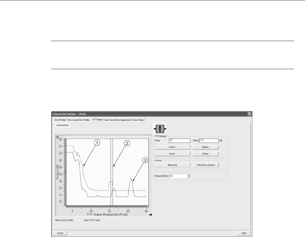
Remote operation
7.1 Operating via SIMATIC PDM
SITRANS LR250 (mA/HART)
Operating Instructions, 08/2014, A5E32220602-AC 91
7.1.6.4
TVT Shaper
Note
Double click on each axis to see the X scale and data scale values. Right
-click or Left-click
on the axis and drag to reposition the scale.
This feature allows you to manually adjust the TVT to avoid false echoes caused by
obstructions. For an explanation see Auto False Echo Suppression (Page 259).
Open the menu
Device – Echo Profile Utilities
and click the tab
TVT Shaper
.
①
TVT
②
Cursor
③
Echo profile
● Initial profile graph is blank upon entry to dialog. Click on
Measure
to view and upload the
current TVT from device.
● Change the position of the cursor on the TVT using the
Point+
and
Point–
buttons: raise and
lower the TVT using
Offset+
and
Offset
-.
● Alternatively, enter values for
Point
and
Offset
directly into the dialog boxes.
● Click on
Transfer to Device
.

Remote operation
7.1 Operating via SIMATIC PDM
SITRANS LR250 (mA/HART)
92 Operating Instructions, 08/2014, A5E32220602-AC
7.1.6.5
Auto false echo suppression
Note
•
Ensure material level is below all known obstructions when using Auto False Echo
Suppression to learn the echo profile. An empty or almost empty vessel is recommended.
•
Note the distance to material level when learning the echo profile, and set Auto False
Echo Suppression Range to a shorter distance to avoid the material echo being screened
out.
•
Set Auto False Echo Suppression and Auto False Echo Suppression Range during
startup, if possible.
•
If the vessel contains an agitator it should be running.
•
Before adjusting these parameters, rotate the device for best signal (lower false-echo
amplitude).
If you have a vessel with known obstructions, use Auto False Echo Suppression to prevent false
echo detection. This feature can also be used if the device displays a false high level, or the
reading is fluctuating between the correct level and a false high level.
The device learns the echo profile over the whole measurement range and the TVT is shaped
around all echoes present at that moment. See Auto False Echo Suppression (Page 259)
for a
more detailed explanation.
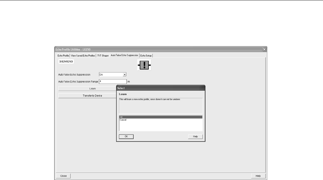
Remote operation
7.1 Operating via SIMATIC PDM
SITRANS LR250 (mA/HART)
Operating Instructions, 08/2014, A5E32220602-AC 93
The learned TVT will be applied over a specified range. The default TVT is applied over the
remainder of the measurement range.
1. Make sure the material level is below all known obstructions.
2. Determine
Auto False Echo Suppression Range
. Measure the actual distance from the
sensor reference point to the material surface using a rope or tape measure. Subtract 0.5 m
(20") from this distance, and use the resulting value.
3. Open the menu
Device – Echo Profile Utilities
and click on the tab
Auto False Echo
Suppression
.
4. Make sure
Auto False Echo Suppression Range
is
On
.
5. Enter the value for
Auto False Echo Suppression Range.
6. Click
Learn
. The message appears:
'This will learn a new echo profile. Once done it cannot
be undone'
. Click
OK
.
7. Once Auto TVT is complete click
Transfer to Device
. To exit click
Close
. Auto TVT is enabled
and the learned TVT will be used.
8. To turn
Auto False Echo Suppression
off or on, reopen the
Auto False Echo Suppression
window, change the Auto False Echo Suppression to
Off
or
On
, click on
Transfer to Device.

Remote operation
7.1 Operating via SIMATIC PDM
SITRANS LR250 (mA/HART)
94 Operating Instructions, 08/2014, A5E32220602-AC
Before Auto False Echo Suppression
①
TVT Hover Level
④
Echo marker
②
Default TVT
⑤
Material level
③
False echo
After Auto False Echo Suppression
①
False echo
④
Material level
②
Learned TVT
⑤
Default TVT
③
Auto False Echo Suppression Range
⑥
Echo marker
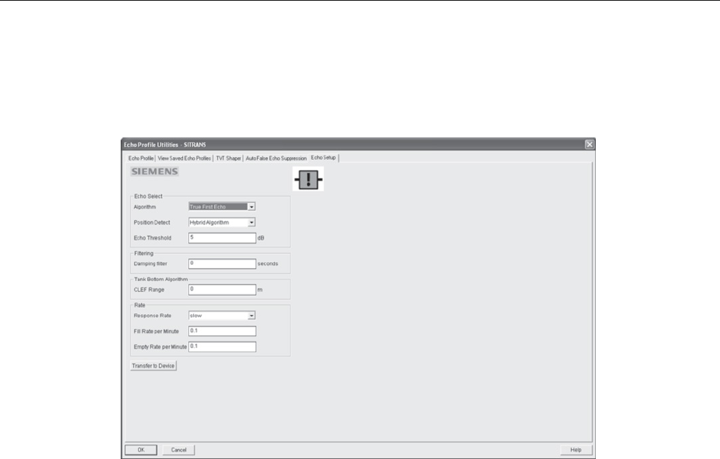
Remote operation
7.1 Operating via SIMATIC PDM
SITRANS LR250 (mA/HART)
Operating Instructions, 08/2014, A5E32220602-AC 95
7.1.6.6
Echo setup
Provides quick access to echo selection, filtering, and response rate parameters.
Open the menu
Device – Echo Profile Utilities
and click on
Echo Setup
.
7.1.6.7
Maintenance
You can set schedules and reminders for:
● device maintenance based on its projected lifetime
● sensor maintenance based on its projected lifetime
● service
● calibration
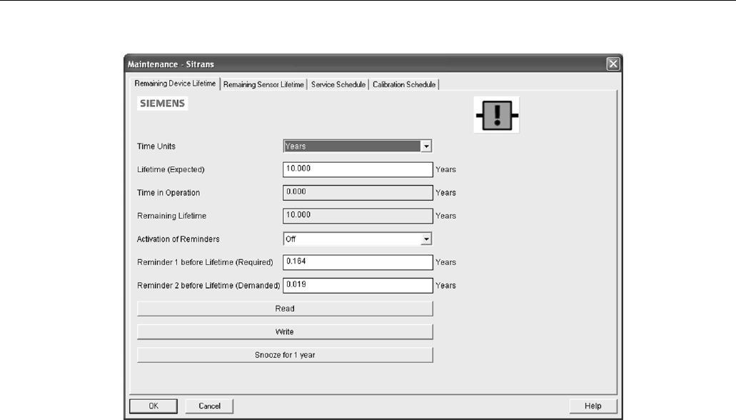
Remote operation
7.1 Operating via SIMATIC PDM
SITRANS LR250 (mA/HART)
96 Operating Instructions, 08/2014, A5E32220602-AC
To set Device/Sensor Maintenance schedules:
1. Open the menu
Device – Maintenance
, and click on the
Remaining Device/Sensor Lifetime
tab.
2. Modify desired values, and if desired, set reminders for either or both of
Reminder 1 before
Lifetime (Required)
/
Reminder 2 before Lifetime (Demanded)
.
3. Click
Write.
4. Click
Read
, to see the effects of your modification.
5. Click
Snooze
to add a year to the Total Expected Device Life.
To set Service/Calibration schedules:
1. Open the menu
Device – Maintenance
, and click on the
Service/Calibration Schedule
tab.
2. Modify desired values and if desired, set reminders for either or both of
Reminder 1 before
Lifetime (Required)
/
Reminder 2 before Lifetime (Demanded)
.
3. Click
Write.
4. Click
Read
, to see the effects of your modification.
5. Click
Service/Calibration Performed
to reset the schedule.

Remote operation
7.1 Operating via SIMATIC PDM
SITRANS LR250 (mA/HART)
Operating Instructions, 08/2014, A5E32220602-AC 97
7.1.6.8
Select analog output
Allows you to set the mA Output to report Level, Distance, Space, or Volume. See
Current
Output Function (2.6.1.)
for an illustration.
If a volume application is selected, mA Output is automatically set to
Volume
. See Analog
Output (Page 262) for more details.
1. Open the menu
Device – Select Analog Output
.
2.
Select Analog Output
window displays the current setting: click
OK
.
3. Select a different setting and click
OK
.
4.
Select Analog Output
window displays the new setting: click
OK
.
7.1.6.9
Self test
Checks memory (RAM and Flash). If there are no errors, returns the message 'Self Test OK.' If
errors are found, returns the message 'Self Test Fails'.
Open the menu
Device – Self Test
, select
Yes
and click
OK
.
7.1.6.10
Loop test
Note
The simulated AO (Analog Output) value influences output to the control s
ystem.
Allows you to input a simulated value (4 mA, 20 mA, or a user-defined value) in order to test the
functioning of the mA connections during commissioning or maintenance of the device. The
range is 3.56 mA to 22.6 mA, see
mA Output Value (2.6.6.).
To simulate a user-defined mA value:
1. Open the menu
Device – Loop Test
.
2. Select
Other
, enter the new value, and click on
OK
. The message ’Field Device fixed at [new
value]’ appears. Click on
OK
. The Loop Test window remains open.
3. When you are ready to end simulation, select
End
and click on
OK
to return the device to the
actual output value.
7.1.6.11
Configuration flag reset
To reset the configuration flag to zero, open the menu
Device – Configuration Flag Reset
and
perform a reset.

Remote operation
7.1 Operating via SIMATIC PDM
SITRANS LR250 (mA/HART)
98 Operating Instructions, 08/2014, A5E32220602-AC
7.1.6.12
Master reset
Factory Defaults
Factory Defaults resets all parameters to the default settings with the following exceptions:
●
Device Address (5.1.)
remains unchanged if the reset command is sent remotely (via AMS,
PDM, DTM, FC375) but is reset to 0 if the reset command is sent via LUI.
●
Write Protect (6.2.1.)
and
PIN to Unlock (6.2.2.)
●
Learned TVT curve, see Auto False Echo Suppression (2.8.7.1)
1. Open the menu
Device – Master Reset
, select
Yes
, and click on
OK
to perform a reset to
Factory Defaults.
2. After the reset is complete upload parameters to the PC/PG. (If you are performing a reset
after replacing the device with a different instrument, do not upload parameters to the
PC/PG).
7.1.6.13
Wear
Reports the number of hours the device has been operating, and the number of times it has
been powered up.
Open the menu
Device – Wear
to view:
● Powered Days
● Power-on Resets
Note
Powered days are whole days only. Fractional days are truncated.
7.1.6.14
HART Communication
Sets the number of request/response preambles (default 5).
The preamble consists of three or more hexadecimal FF characters (all 1s). This allows the
receiving modem to get its frequency-detection circuits synchronized to the signal after any
pause in transmission.
We recommend you do not change the default value (5).
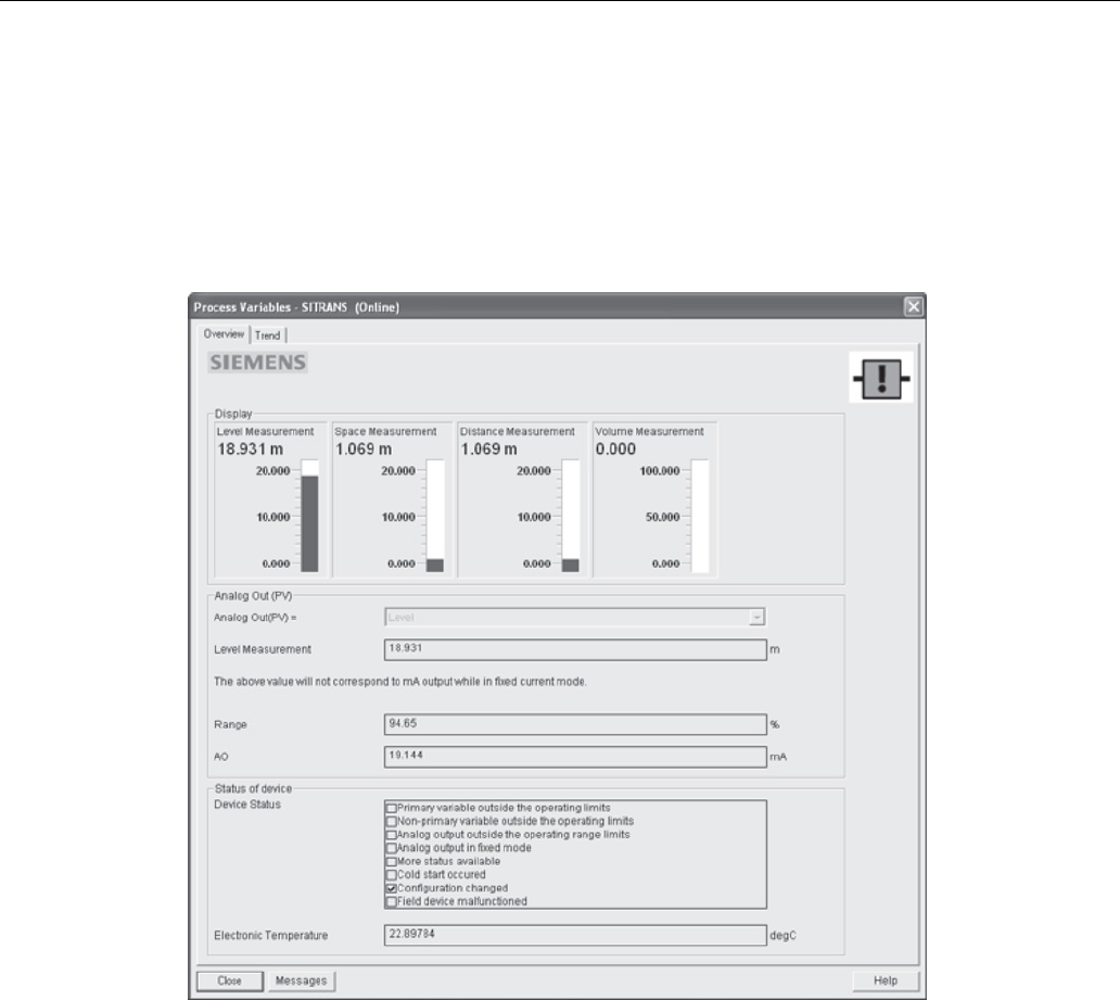
Remote operation
7.1 Operating via SIMATIC PDM
SITRANS LR250 (mA/HART)
Operating Instructions, 08/2014, A5E32220602-AC 99
7.1.6.15
Process variables
To compare outputs in real time open the menu
View – Process Variables
and click on
Overview
to see reading (level, space, distance, volume); analog output; device status; and current
electronics temperature.
To see highest and lowest electronics temperatures, navigate to
Level Meter > Maintenance and
Diagnostics > Electronics Temperature
.
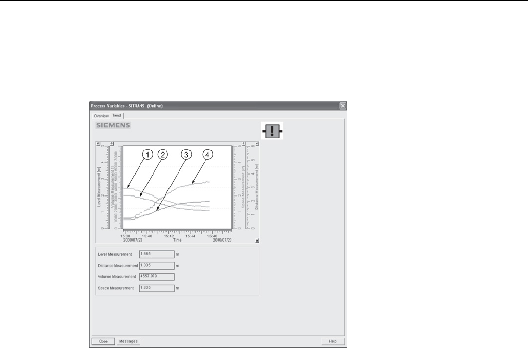
Remote operation
7.1 Operating via SIMATIC PDM
SITRANS LR250 (mA/HART)
100 Operating Instructions, 08/2014, A5E32220602-AC
7.1.6.16
Trend
Open the menu
View – Process Variables
and click on
Trend
.
Four trend lines can be monitored (distinguished by color in SIMATIC PDM):
①
Space
②
Distance
③
Level
④
Volume
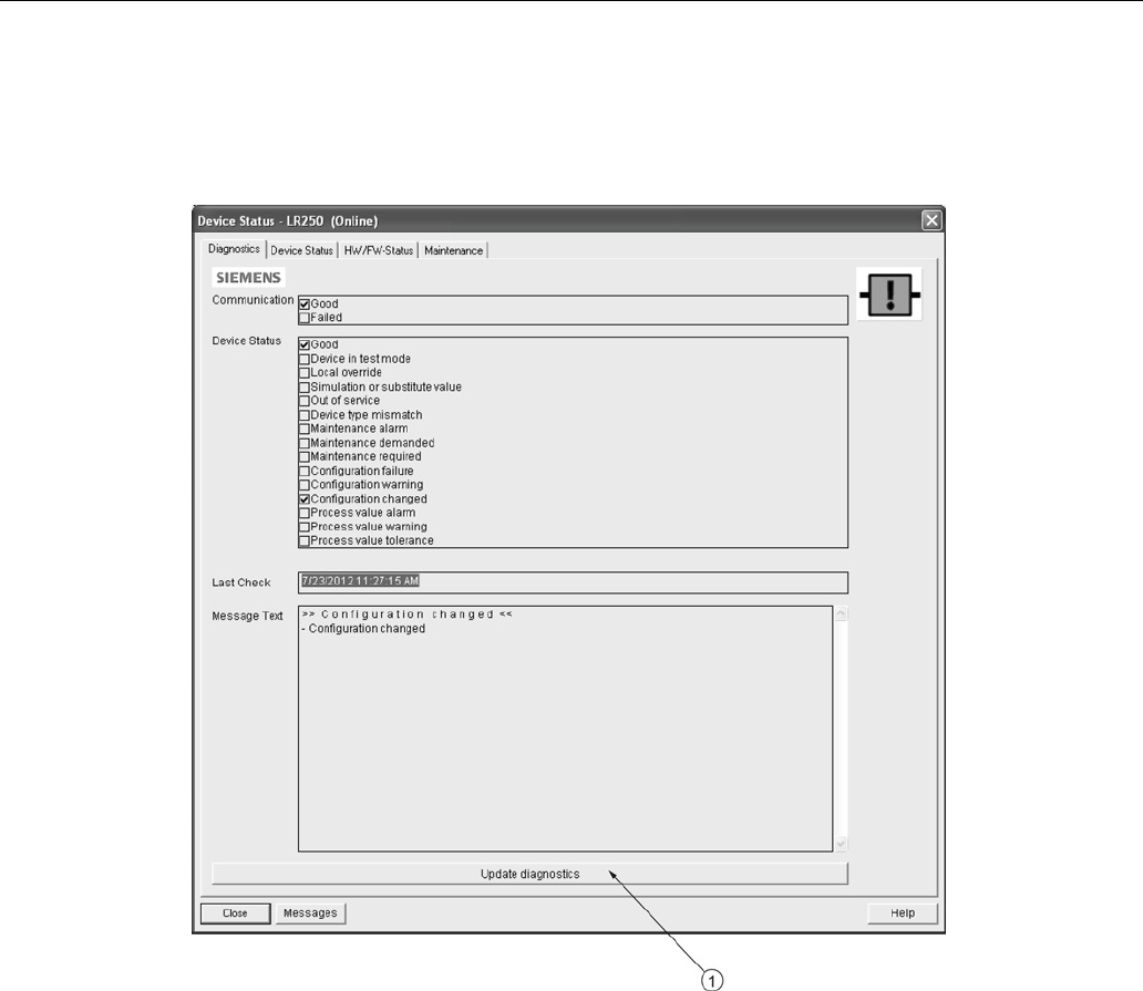
Remote operation
7.1 Operating via SIMATIC PDM
SITRANS LR250 (mA/HART)
Operating Instructions, 08/2014, A5E32220602-AC 101
7.1.6.17
Device status
Open the menu
View – Device Status
to view Diagnostics, Device Status, Hardware/ Firmware
(HW/FW) Status, and Maintenance status.
①
update diagnostics
In the Diagnostics window, click on
Update diagnostics
to update diagnostic information and
refresh linked icons.
7.1.6.18
Update
Open the menu
View – Update
to refresh the screen.
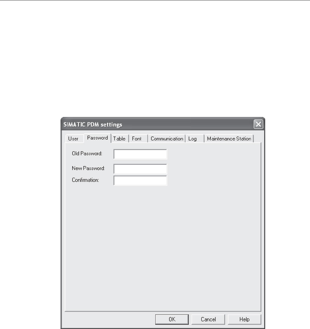
Remote operation
7.1 Operating via SIMATIC PDM
SITRANS LR250 (mA/HART)
102 Operating Instructions, 08/2014, A5E32220602-AC
7.1.6.19
Security
A password option protects security and communication control parameters from modification by
a maintenance user.
When you open a project the
User
dialog window provides two options: maintenance or
specialist. If a password has been set it will not be possible to open the project as a specialist
without it. A maintenance user will be able to open the project without a password but will not
have access to security and communication control parameters.
1. Open a project, double-click on the device icon, and in the
User
window select
Specialist
.
2. Open the menu
Options – Settings
and click on the
Password
tab.
3. Enter a new password and re-enter it in the
Confirmation
window. Click on
OK
.

Remote operation
7.2 Operating via AMS Device Manager
SITRANS LR250 (mA/HART)
Operating Instructions, 08/2014, A5E32220602-AC 103
7.2
Operating via AMS Device Manager
AMS Device Manager is a software package that monitors the process values, alarms and
status signals of the device. Please consult the operating instructions or online help for details
on using AMS Device Manager. You can find more information at:
Emerson (http://www.emersonprocess.com/AMS/)
Application Guides for setting up Siemens HART devices with AMS Device Manager are
available on our website:
Process automation (www.siemens.com/processautomation)
7.2.1
Functions in AMS Device Manager
Note
While the device is in PROGRAM mode the output r
emains fixed and does not respond to
changes in the device.
7.2.1.1
AMS function overview
AMS Device Manager monitors the process values, alarms and status signals of the device. It
allows you to display, compare, adjust, verify, and simulate process device data.
Parameters organized into three main function groups allow you to configure and monitor the
device:
● Configure/Setup
● Device Diagnostics (read only)
● Process Variables (read only)
See AMS Menu Structure (Page 122) for a chart and Changing parameter settings using AMS
Device Manager (Page 111) for more details. The menu structure for AMS Device Manager is
almost identical to that for the LCD.
Remote operation
7.2 Operating via AMS Device Manager
SITRANS LR250 (mA/HART)
104 Operating Instructions, 08/2014, A5E32220602-AC
7.2.1.2
Features of AMS Device Manager
The graphic interface in the radar device makes monitoring and adjustments easy.
Feature
Function
Quick Start (Page 107)
Device configuration for simple applications
Echo Profile (Page 116)
Echo profile viewing
TVT (Page 115)
Screen out false echoes
Linearization (Page 109)
Volume measurement in an irregular vessel
Process Variables (Page 120)
Monitor process variables and level trend
Security (Page 118) Protect security and communication parameters from
modification by the maintenance user
7.2.1.3
Electronic Device Description (EDD)
The EDDs are linked to the type, version of configuration software, and protocol being used.
Select the LR250 AMS EDD for the version of AMS installed. EDDs can be downloaded from our
website, see Product page (http://www.siemens.com/LR250).
The HART EDD for LR250 is labeled as supporting AMS Device Manager version 9.5. This EDD
is also operational with AMS version 9.0 and 10.1. There is also an application guide that details
how to use the Hart Communication Foundation EDDs in AMS version 11.5 and above. There is
no EDD for the LR250 for AMS version 10.5 to 11.1.
Please check the product page for updated EDDs and application guide.
7.2.1.4
Configuring a new device
1. Check our website to make sure you have the most recent EDD.
Product page (http://www.siemens.com/LR250)
Go to
Support > Software Downloads
and if necessary download it. Save the files to your
computer, and extract the zipped file to an easily accessed location.
2. Launch
AMS Device Manager– Add Device Type
, browse to the unzipped EDD file and select
it.
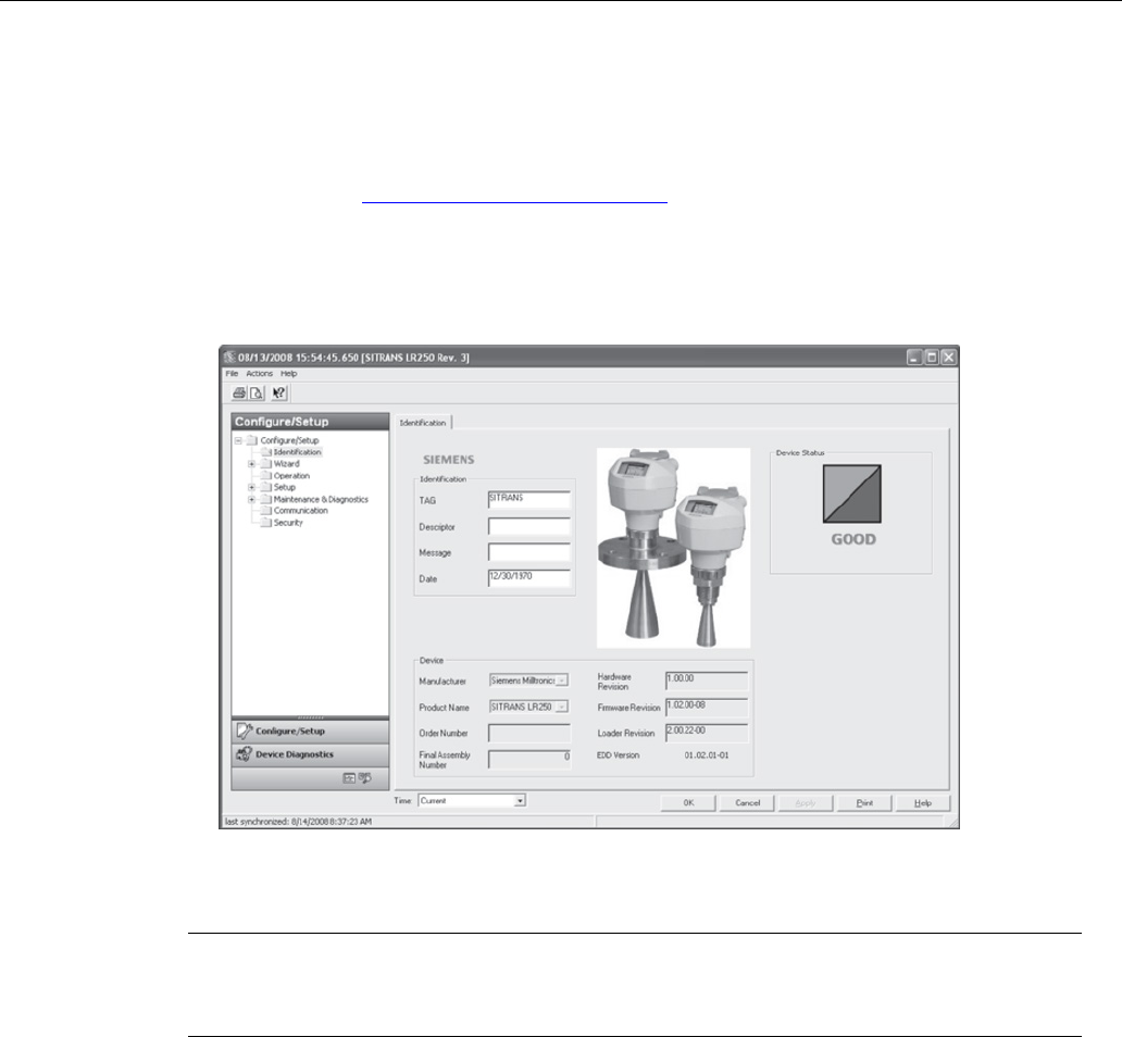
Remote operation
7.2 Operating via AMS Device Manager
SITRANS LR250 (mA/HART)
Operating Instructions, 08/2014, A5E32220602-AC 105
7.2.1.5
Startup
1.
Launch AMS Device Manager
. (Application Guides for setting up HART devices with AMS
Device Manager can be downloaded from our website:
Product page (http://www.siemens.com/LR250)
2. In
Device Connection View
right-click on the device icon and select
Scan Device
to upload
parameters from the device.
3. Double click the device icon to open the startup screen. The startup screen shows device
identification details, and a navigation window on the left-hand side of the screen.
Master reset
Note
Device Address (5.1.)
remains unchanged if the reset command is sent remotely (via AMS,
PDM, DTM, FC375) but is reset to 0 if the reset command is sent via LUI.
● Navigate to
Configure/Setup > Operation
● In the
General
field click on
Master Reset
and accept the option
Factory Defaults
.
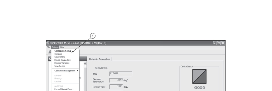
Remote operation
7.2 Operating via AMS Device Manager
SITRANS LR250 (mA/HART)
106 Operating Instructions, 08/2014, A5E32220602-AC
7.2.1.6
Pull-down menu access
①
Action menu items
A pull-down menu under
Actions
gives alternative access to several features.
Scan Device
• Open the menu
Actions – Scan Device
.
•
Scan Device
uploads parameters from the device (synchronizes parameters).
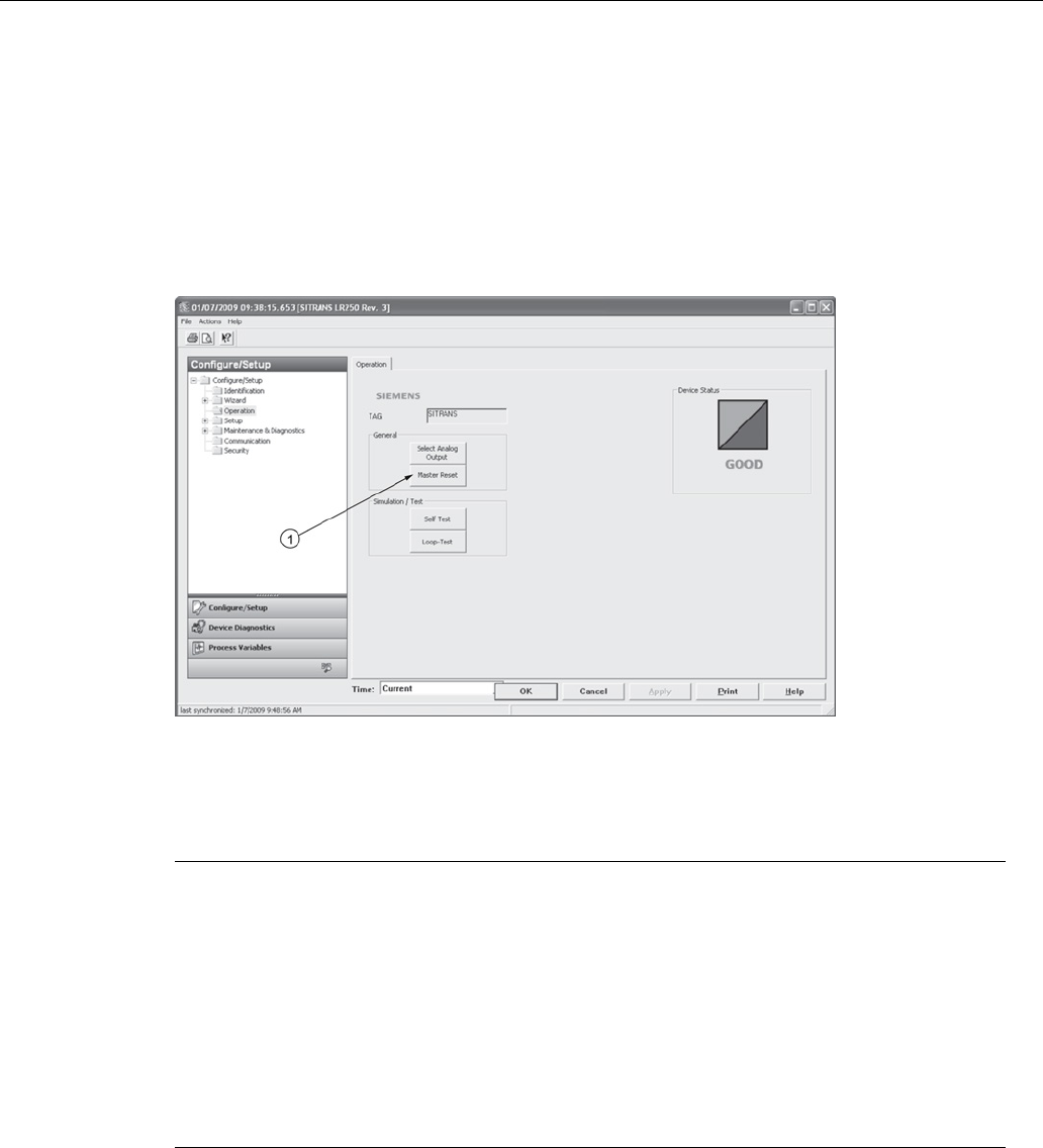
Remote operation
7.2 Operating via AMS Device Manager
SITRANS LR250 (mA/HART)
Operating Instructions, 08/2014, A5E32220602-AC 107
7.2.1.7
Device configuration
1. Navigate to
Configure/Setup > Operation
and click to open the dialog window.
2. In the
General
field, click on
Master Reset
and perform a reset to Factory Defaults.
3. Open the pull-down menu
Actions – Scan Device
to synchronize parameters (upload
parameters from the device to AMS).
4. Configure the device via the Quick Start wizard.
①
Master reset
7.2.1.8
Quick Start Wizard via AMS Device Manager
Note
•
A reset to Factory Defaults should be performed before running the Quick Start Wizard if
device has been used in a previous application. See Master Reset (Page 105).
•
The layout of the dialog boxes shown may vary according to the resolution setting for
your computer monitor.
•
At each step, you can accept the default values without modification and click on the next
step to proceed.
•
After modifying parameters click on
Apply
inside the Quick Start window to write the new
values to the device.
•
Click on
OK
only if you wish to update all parameters to the device and close AMS.
A Wizard provides an easy 5-step Quick Start procedure that configures the device for a simple
application.
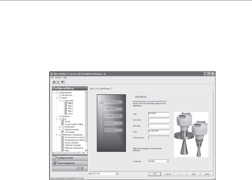
Remote operation
7.2 Operating via AMS Device Manager
SITRANS LR250 (mA/HART)
108 Operating Instructions, 08/2014, A5E32220602-AC
Quick Start
Step 1 – Identification
1. Navigate to
Configure/Setup > Wizard > Quick Start
.
2. Click on
Step 1
.
3. You can accept the default values without modification. (Description, Message, and
Installation Date fields can be left blank.) If desired, make changes then click on
Apply
.
Step 2 – Application
1. Click on
Step 2
.
2. Select the application type (Level/vessel, Level/stillpipe, Level/bypass pipe, Volume/vessel,
Volume/stillpipe, or Volume/bypass pipe) and the material (Liquid or Low dielectric liquid).
3. Click on
Apply
.
Step 3 – Vessel Shape
1. Click on
Step 3
.
2. Select a predefined vessel shape. To describe a more complex shape see Linearization
(Page 109).
3. Click on
Apply
.

Remote operation
7.2 Operating via AMS Device Manager
SITRANS LR250 (mA/HART)
Operating Instructions, 08/2014, A5E32220602-AC 109
Step 4 – Ranges
1. Click on
Step 4
.
2. Change units if desired (in meters by default).
3. Set High and Low Calibration points.
4. To convert the reading from level to volume enter a value for Maximum Volume.
5. If a vessel shape with parabolic ends has been selected, set dimensions
A
and
L
.
6. Click on
Apply
.
Step 5 – Summary
Check parameter settings, and click on
Cancel
to abort, or
Apply
to transfer values to the device.
Linearization
You can use the linearization feature to define a more complex vessel shape and enter up to 32
level breakpoints where the corresponding volume is known. The values corresponding to 100%
and 0% levels must be entered. The breakpoints can be ordered from top to bottom, or the
reverse.
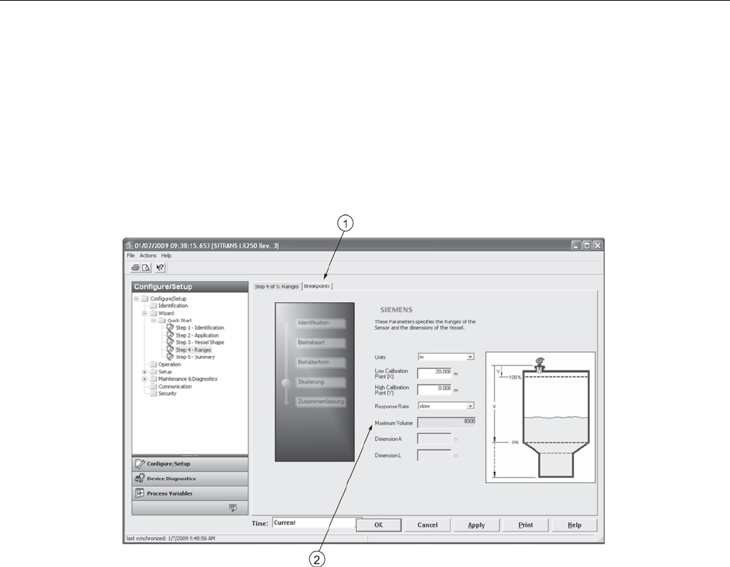
Remote operation
7.2 Operating via AMS Device Manager
SITRANS LR250 (mA/HART)
110 Operating Instructions, 08/2014, A5E32220602-AC
Using linearization via the Quick Start wizard
Navigate to
Configure/Setup > Wizard > Quick Start
.
In
Step 1 – Identification,
make any desired modifications and click on
Apply
.
In
Step 2 – Application,
select a level application and liquid as a material.
In
Step 3 – Vessel Shape
, choose the vessel shape option
Linearization Table
.
In
Step 4 – Ranges
, enter a value for maximum volume.
①
Breakpoints
②
Maximum volume
1. Click on the
Breakpoints
tab and enter values for level and volume for up to
32
breakpoints.
2. Navigate to
Configure/Setup > Setup > Linearization
and click on
Characteristic
to preview
the characteristic curve of the vessel breakpoints. (The conversion will function correctly even
if not all breakpoints are entered, but the curve will display correctly only if all breakpoints are
entered.)
3. In
Step 5 – Summary
, check parameter values. Click on the appropriate step menu to return
and revise values, or click on a different menu to exit
Quick Start.
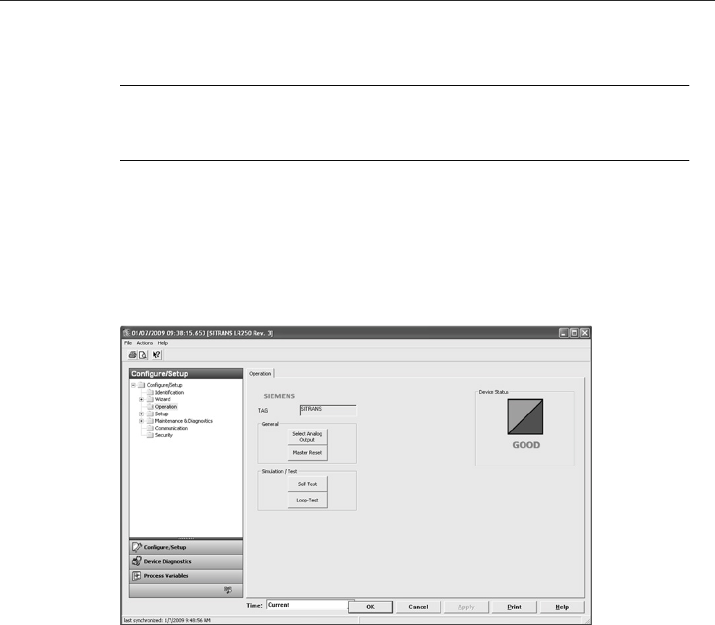
Remote operation
7.2 Operating via AMS Device Manager
SITRANS LR250 (mA/HART)
Operating Instructions, 08/2014, A5E32220602-AC 111
Changing parameter settings using AMS Device Manager
Note
For a complete list of parameters, see
Parameter Reference (Page 127).
For more detailed explanations of the parameters listed below see the pages referenced.
1. Adjust parameter values in the parameter value field in Configure/Setup view, then click on
Apply
to write the new values to the device. The parameter field will display in yellow until the
value has been written to the device.
2. Click on
OK
only if you wish to update all parameters and exit AMS.
Operation
Navigate to
Configure/Setup > Operation
and click on
Operation
to open the dialog window for
access to:
General
● Select Analog Output [see Select Analog Output (Page 97)]
● Master Reset [see Master Reset (Page 98)]
Simulation/Test
● Self Test [see Self Test (Page 97)]
● Loop Test [see Loop Test (Page 97)]
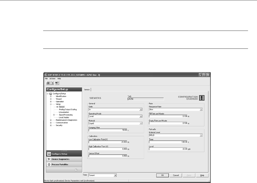
Remote operation
7.2 Operating via AMS Device Manager
SITRANS LR250 (mA/HART)
112 Operating Instructions, 08/2014, A5E32220602-AC
Setup
Note
For more detailed explanations of the paramet
ers listed below see the pages referenced.
Sensor
Navigate to
Configure/Setup > Setup
and click on
Sensor
for access to:
General [see Sensor (2.2.)]
● Units
● Operating Mode
● Material
● Damping Filter
Calibration [see Calibration (2.3.)]
● Low Calibration Point
● High Calibration Point
● Sensor Offset
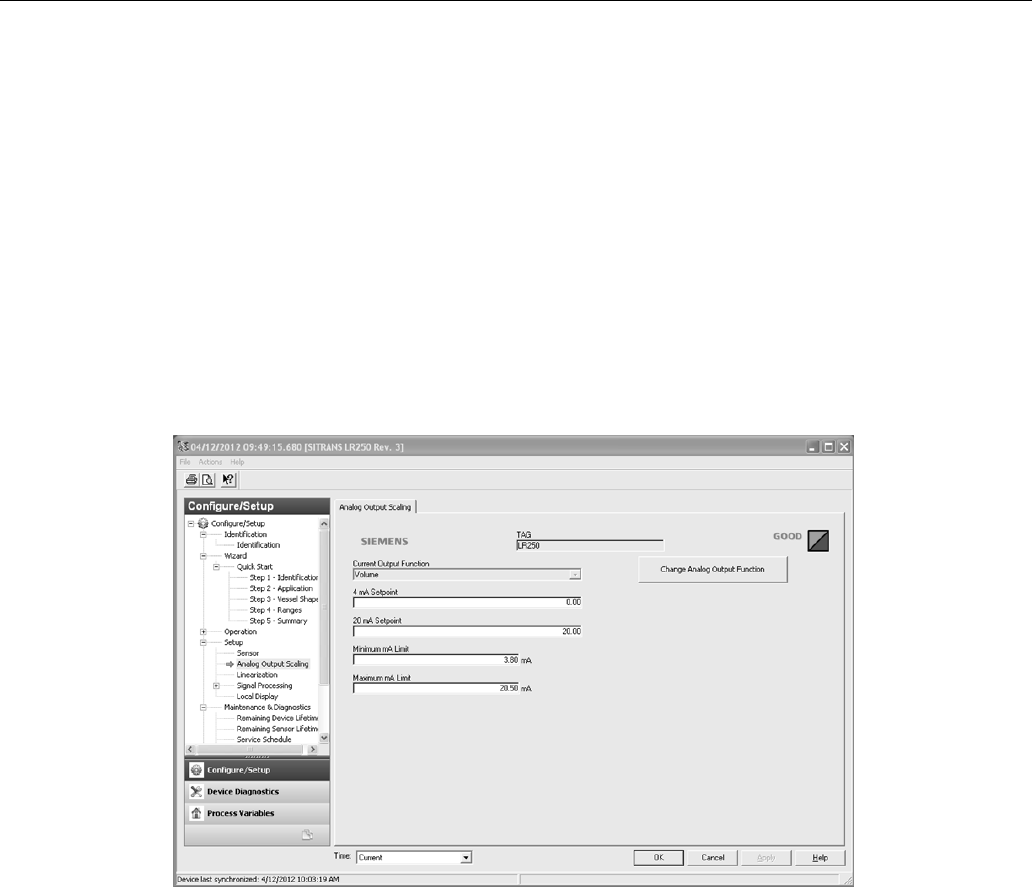
Remote operation
7.2 Operating via AMS Device Manager
SITRANS LR250 (mA/HART)
Operating Instructions, 08/2014, A5E32220602-AC 113
Rate [see Rate (2.4.)]
● Response Rate
● Fill Rate per Minute
● Empty Rate per Minute
Fail-safe [see Fail-safe (2.5.)]
● Material level
● Timer
● Level
Analog Output Scale
Navigate to
Configure/Setup > Setup
and click on
Analog Output Scaling
for access to:
Analog Output Scaling [see
Analog Output Scaling (2.6.)
]
● Current Output Function
● 4 mA Setpoint
● 20 mA Setpoint
● Minimum mA Limit
● Maximum mA Limit
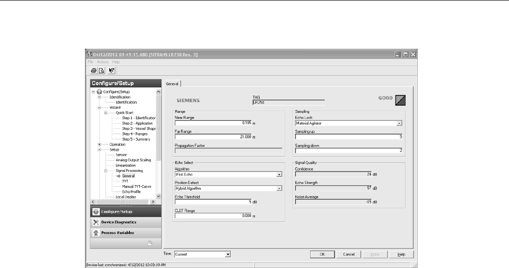
Remote operation
7.2 Operating via AMS Device Manager
SITRANS LR250 (mA/HART)
114 Operating Instructions, 08/2014, A5E32220602-AC
Signal Processing
General
Navigate to
Configure/Setup > Setup > Signal Processing
and click on
General
for access to:
Range
[see
Signal Processing (2.8.)
]
● Near Range
● Far Range
● Propagation Factor
Echo Select [see Echo Select (2.8.4.)]
● Algorithm
● Position Detect
● Echo Threshold
● CLEF Range
Sampling [see Sampling (2.8.5.)]
● Echo Lock
● Sampling Up
● Sampling Down
Signal Quality
● Confidence
● Echo Strength
● Noise Average
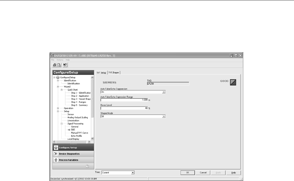
Remote operation
7.2 Operating via AMS Device Manager
SITRANS LR250 (mA/HART)
Operating Instructions, 08/2014, A5E32220602-AC 115
TVT
Modify the TVT to screen out false echoes. See Auto False Echo Suppression (2.8.7.1.)
(Page 259).
Navigate to
Configure/Setup > Setup > Signal Processing
and click on
TVT
. Click on one of the
two tabs to access the parameters listed:
TVT Setup [see TVT setup (2.8.7.)]
● Auto False Echo Suppression
● Auto False Echo Suppression Range
● Hover Level
● Shaper Mode
TVT Shaper
● Shaper breakpoints 1 to 40. (Turn
TVT Setup/Shaper Mode
on to activate.)
Manual TVT Curve
Displays the effects of the TVT shaper modifications. Navigate to
Configure/Setup > Setup >
Signal Processing
and click on
Manual TVT Curve
.

Remote operation
7.2 Operating via AMS Device Manager
SITRANS LR250 (mA/HART)
116 Operating Instructions, 08/2014, A5E32220602-AC
Echo Profile
● Navigate to
Configure/Setup > Setup > Signal Processing
and click on
Echo Profile
.
● Select
Standard
operation for faster display.
Local Display
Navigate to
Configure/Setup > Setup > Local Display
for access to:
● Language
● LCD Fast Mode [see
LCD Fast Mode (4.9.)
]
● LCD Contrast [see
LCD Contrast (4.10.)
]
7.2.2
Maintenance and diagnostics
Navigate to
Maintenance and Diagnostics
for access to:
Remaining Device Lifetime [see Remaining Device Lifetime (4.2.)]
● Lifetime (expected)
● Time in Operation
● Remaining Lifetime
● Activation of Reminders
● Reminder 1 before Lifetime (Required)
● Reminder 2 before Lifetime (Demanded)
Remaining Sensor Lifetime [see Remaining Sensor Lifetime (4.3.)]
● Lifetime (expected)
● Time in Operation
● Remaining Lifetime
● Activation of Reminders
● Reminder 1 before Lifetime (Required)
● Reminder 2 before Lifetime (Demanded)

Remote operation
7.2 Operating via AMS Device Manager
SITRANS LR250 (mA/HART)
Operating Instructions, 08/2014, A5E32220602-AC 117
Service Schedule [see Service Schedule (4.4.)]
● Service Interval
● Time Since Last Service
● Time Until Next Service
● Activation of Reminders
● Reminder 1 before Service (Required)
● Reminder 2 before Service (Demanded)
Calibration Schedule [see Calibration Schedule (4.5.)]
● Calibration Interval
● Time Since Last Calibration
● Time Until Next Calibration
● Activation of Reminders
● Reminder 1 before Calibration (Required)
● Reminder 2 before Calibration (Demanded)
Electronic Temperature
● Electronic Temperature
● Lowest Value
● Highest Value
Wear
● Powered Days
● Poweron Resets
See Wear via SIMATIC PDM (Page 98) for more detail.
7.2.3
Communication
Navigate to
Communication
to read the following:
Tag; Manufacturer’s ID; Device ID; Product ID; Device Revision; EDD Revision; Universal
Command Revision

Remote operation
7.2 Operating via AMS Device Manager
SITRANS LR250 (mA/HART)
118 Operating Instructions, 08/2014, A5E32220602-AC
7.2.4
Security
Navigate to
Configure/Setup > Security
to access:
Remote Access [see Remote Access (6.1.)]
Note
If access control is changed to limit remote access, it can only be reset via the handheld
programmer. See Access Control (6.1.1.)
.
● Write Protect (read only)
● Access Control
Local Access [see Local Access (6.2.)]
● Local Write Protected
● PIN to Unlock
See also Password Protection (Page 121).
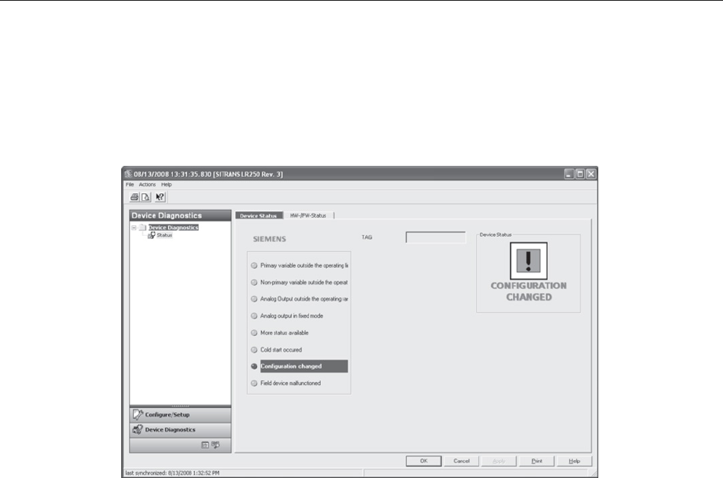
Remote operation
7.2 Operating via AMS Device Manager
SITRANS LR250 (mA/HART)
Operating Instructions, 08/2014, A5E32220602-AC 119
7.2.5
Device Diagnostics
Click on the
Device Diagnostics
bar at the bottom of the navigation window, for access to:
Device Status
Hardware/Firmware Status
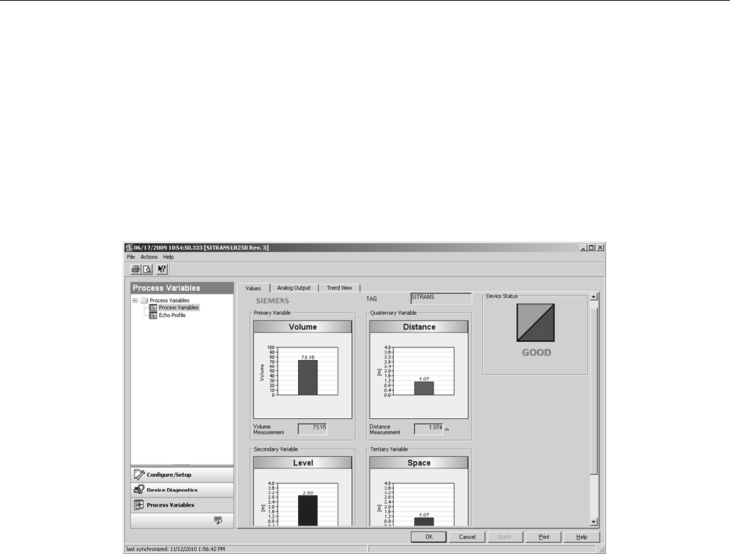
Remote operation
7.2 Operating via AMS Device Manager
SITRANS LR250 (mA/HART)
120 Operating Instructions, 08/2014, A5E32220602-AC
7.2.5.1
Process variables
To compare outputs in real time click on
Process Variables
at the bottom of the navigation
window for access to:
Process Variables
● Values (level, volume, space, distance)
● Analog Output
● Trend View
Echo Profile
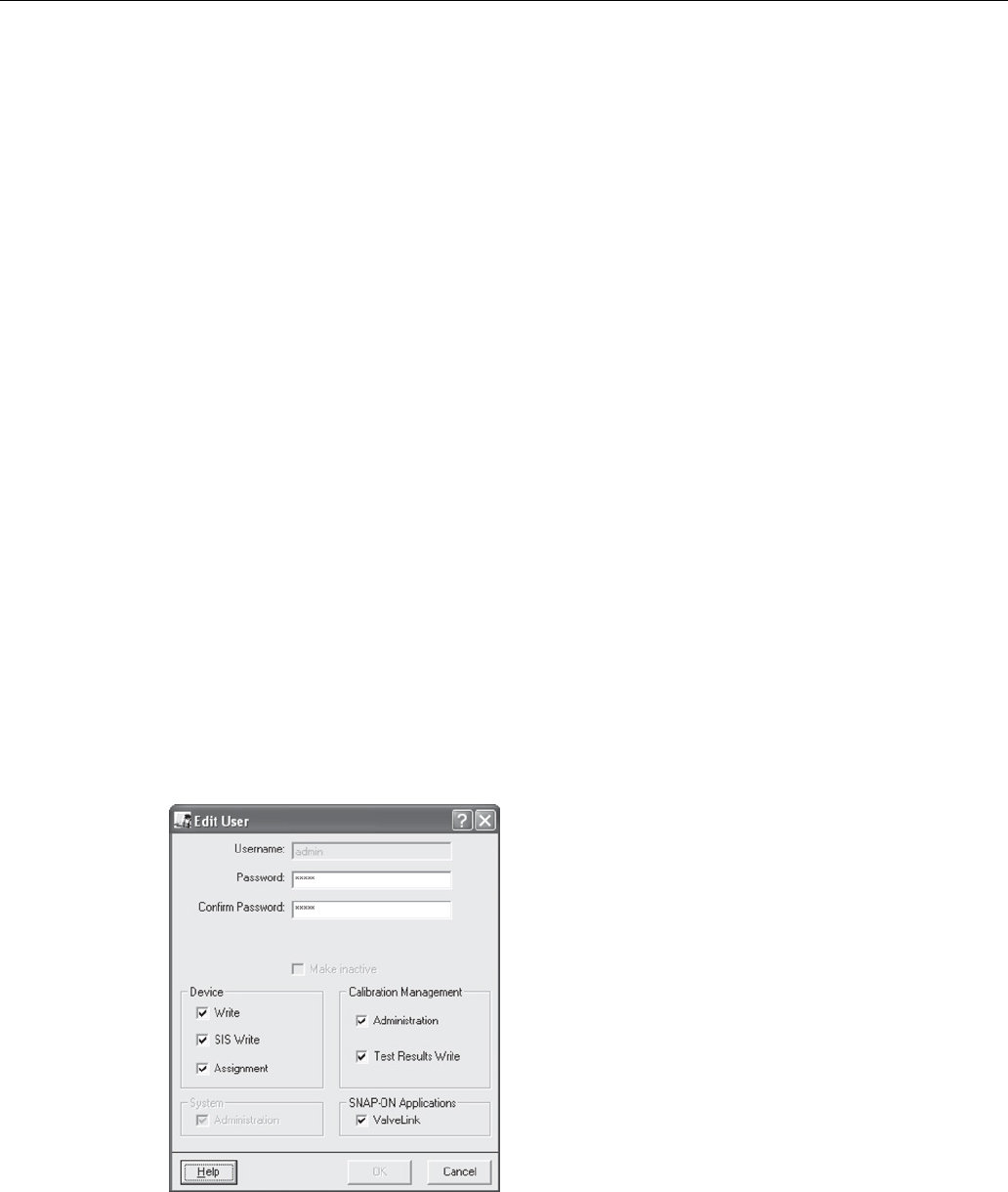
Remote operation
7.2 Operating via AMS Device Manager
SITRANS LR250 (mA/HART)
Operating Instructions, 08/2014, A5E32220602-AC 121
7.2.5.2
Password protection
An AMS Device Manager administrator can configure the user to require a password. The use of
passwords is recommended. A password should be assigned to the ’admin’ username
immediately after installing AMS Device Manager.
Each user is given an AMS Device Manager username and password and required to enter
them when they start AMS Device Manager. Access to functions depends on the level of
permissions granted.
Login types
● standard, local, or domain
A standard user can change their password in AMS Device Manager. A Local or Domain
Windows user cannot change their password using AMS Device Manager and must request
their network administrator to do so.
7.2.5.3
User Manager utility
Usernames, passwords, and permissions, are assigned to users by an AMS Device Manager
administrator, using the User Manager utility on the Server Plus Station. Only a user with AMS
Device Manager System Administration rights can log in to User Manager.
To configure a new user/edit existing user:
1. From the Windows taskbar select:
Start > AMS Device Manager > User Manager
.
2. In the User Manager window click on
Add User
.
The Add User Wizard dialog allows you to:
● select a user type, standard (AMS Device Manager) or Window user.
● enter the username and password, and set permissions
● edit existing users
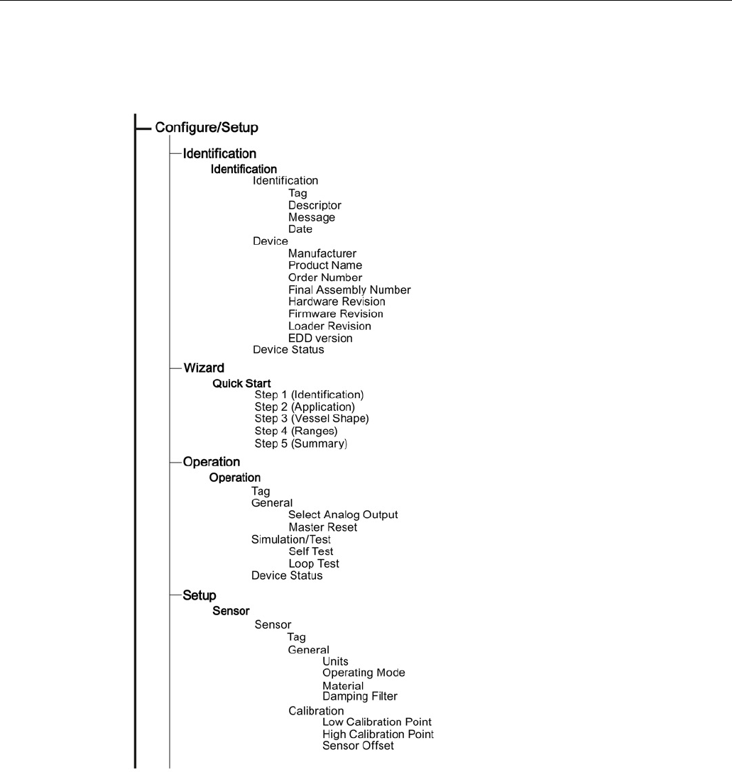
Remote operation
7.2 Operating via AMS Device Manager
SITRANS LR250 (mA/HART)
122 Operating Instructions, 08/2014, A5E32220602-AC
7.2.6
AMS menu structure
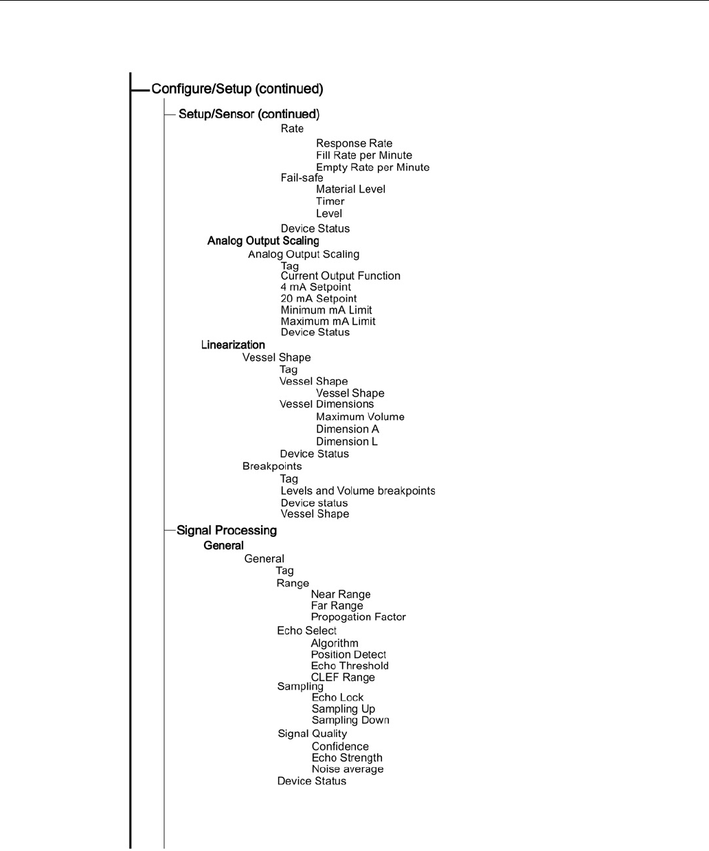
Remote operation
7.2 Operating via AMS Device Manager
SITRANS LR250 (mA/HART)
Operating Instructions, 08/2014, A5E32220602-AC 123
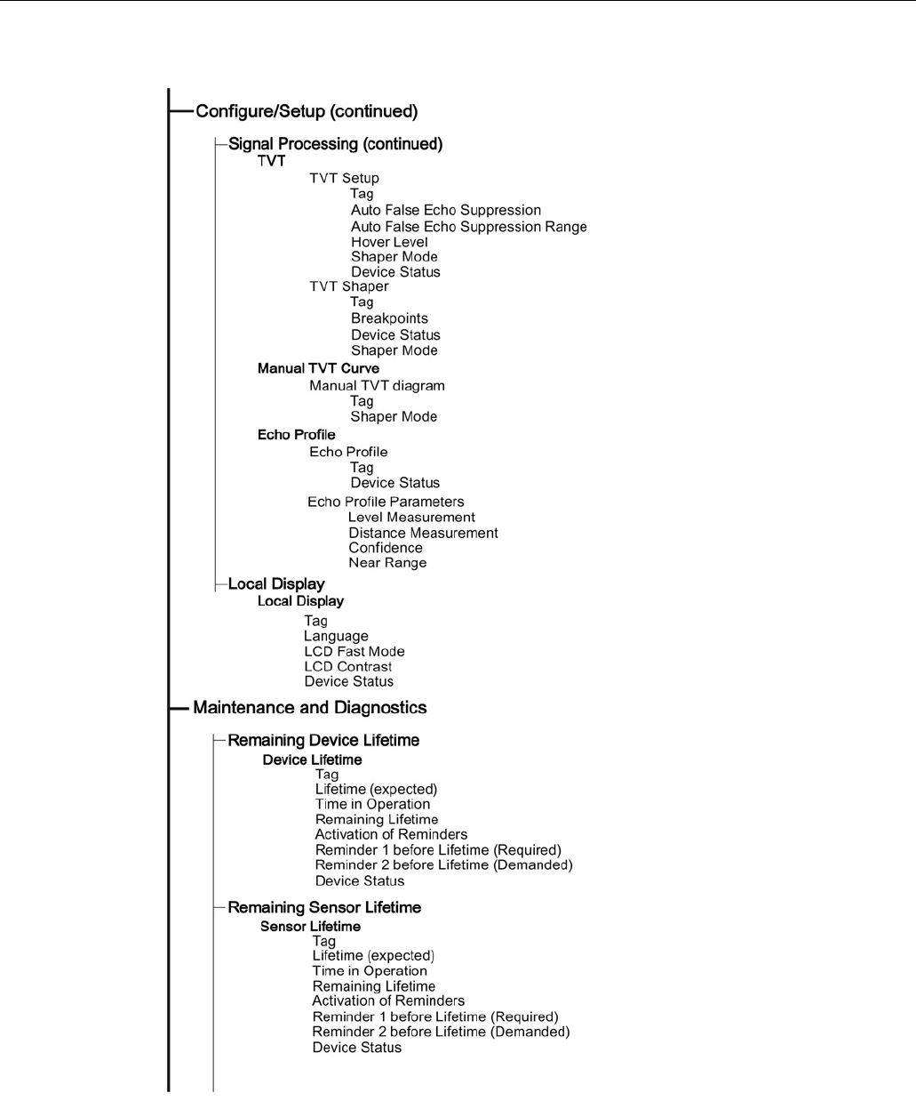
Remote operation
7.2 Operating via AMS Device Manager
SITRANS LR250 (mA/HART)
124 Operating Instructions, 08/2014, A5E32220602-AC
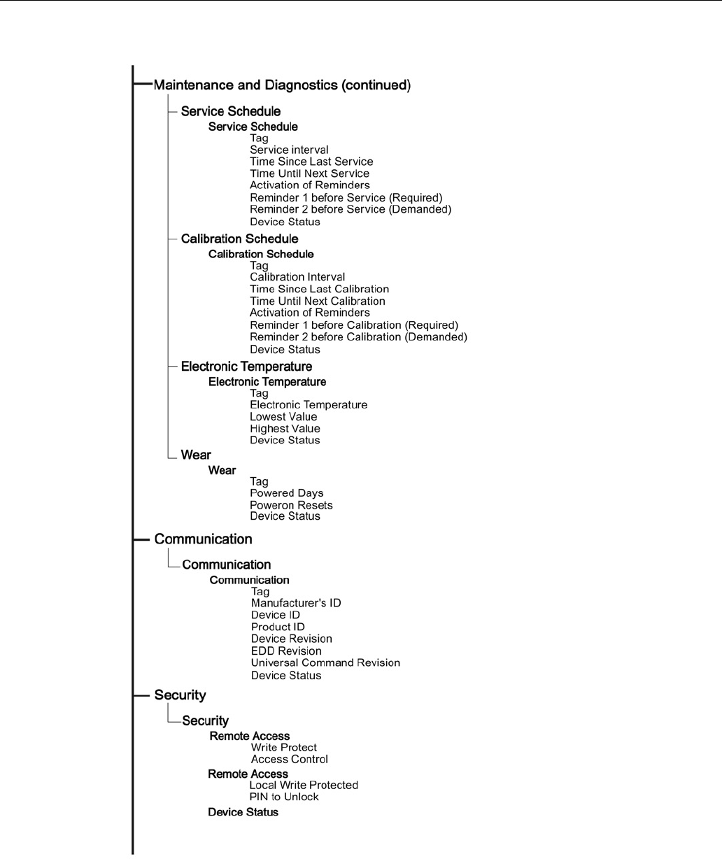
Remote operation
7.2 Operating via AMS Device Manager
SITRANS LR250 (mA/HART)
Operating Instructions, 08/2014, A5E32220602-AC 125
Remote operation
7.3 Operating via FDT (Field Device Tool)
SITRANS LR250 (mA/HART)
126 Operating Instructions, 08/2014, A5E32220602-AC
7.3
Operating via FDT (Field Device Tool)
FDT is a standard used in several software packages designed to commission and maintain field
devices. Two commercially available FDTs are PACTware and Fieldcare.
Functionally FDT is very similar to PDM. See Operating via SIMATIC PDM (Page 77) for more
detail.
● To configure a field device via FDT you need the DTM (Device Type Manager) for the device.
● To configure a field device via SIMATIC PDM, you need the EDD (Electronic Data
Description) for the device.
7.3.1
Device Type Manager (DTM)
A DTM is a type of software that ’plugs into’ FDT. It contains the same information as an EDD
but an EDD is independent of the operating system.
7.3.2
SITRANS DTM
● SITRANS DTM is an EDDL interpreter developed by Siemens to interpret the EDD for that
device.
● To use SITRANS DTM to connect to a device, you must first install SITRANS DTM on your
system and then install the device EDD written for SITRANS DTM.
● You can download SITRANS DTM from the Siemens service and support website. Go to
Service & Support (http://www.siemens.com/automation/service&support), click on
Product
Support
, and drill down to
Product Information/Automation Technology/Sensor
systems/Process Instrumentation/Software & Communications
.
7.3.3
The device EDD
The SITRANS LR250 HART EDD for SITRANS DTM can be downloaded from our website:
Product page (http://www.siemens.com/LR250).
Go to
Support > Software Downloads
.
7.3.4
Configuring a new device via FDT
The full process to configure a field device via FDT is outlined in an Application Guide which can
be downloaded from our website under
Support
> Application Guides
.
Product page (http://www.siemens.com/LR250)

SITRANS LR250 (mA/HART)
Operating Instructions, 08/2014, A5E32220602-AC 127
Parameter reference
8
Note
•
Parameter names and menu structure are almost identical for SIMATIC PDM and the
local user interface (LUI).
•
Default settings in the parameter tables are indicated with an asterisk (*) unless explicitly
stated.
•
Mode
toggles between
PROGRAM
and
Measurement
Modes.
•
For Quick Access to parameters via the handheld programmer, press
Home
, then
enter the menu number, for example:
2.2.1.
•
In Navigation mode
, ARROW keys ( )
navigate the menu in the direction of
the arrow.
•
Press
RIGHT arrow
to open
Edit
Mode, or to save a modification.
Parameters are identified by name and organized into function groups. See LCD menu structure
(Page 293) for a chart. For AMS Device Manager the structure varies slightly.
Parameters accessible via the handheld programmer are followed by the device menu number
in parenthesis. Parameters not followed by a number are accessible only via remote operation.
For more details see:
● Operating via SIMATIC PDM (Page 77)
● Operating via AMS Device Manager (Page 103)
Quick Start (1.)
Wizards provide step-by-step procedures to configure the device, filter out false echoes, and
upload and download parameters and firmware to the optional display for easy configuration of
multiple devices.

Parameter reference
SITRANS LR250 (mA/HART)
128 Operating Instructions, 08/2014, A5E32220602-AC
Quick Start Wizard (1.1.)
From measurement screen, press
RIGHT arrow
twice to open the Quick Start Wizard menu.
Select a wizard, press
RIGHT arrow
to open the first step, and follow the instructions.
Note
Do not use the Quick Start Wizard to modify individual parameters. (Perform customization
only after the Quick Start has been completed.)
● See Quick Start Wizard via the handheld programmer (Page 64).
● See Quick Start Wizard via SIMATIC PDM (Page 77).
● See Quick Start Wizard via AMS Device Manager (Page 107).
Setup (2.)
Note
Default settings in the parameter tables are indicated with an asterisk (*) unless exp
licitly
stated.
Device (2.1.)
Hardware Revision (2.1.1.)
Corresponds to the electronics hardware of the SITRANS LR250.
Firmware Revision (2.1.2.)
Corresponds to the firmware that is embedded in the SITRANS LR250.
Loader Revision (2.1.3.)
Corresponds to the software used to update the SITRANS LR250.
Order Option (2.1.4.)
Read only. Displays the device type: standard or NAMUR NE 43-compliant.
Menu Timeout (2.1.5.)
Time menu stays visible before switching back to Measurement view if no key is pressed.

Parameter reference
SITRANS LR250 (mA/HART)
Operating Instructions, 08/2014, A5E32220602-AC 129
Sensor (2.2.)
Units (2.2.1.)
PV (Primary Value) and SV (Secondary Sensor measurement units). Used in setting High/Low
Calibration Point, and displayed on LCD and in PDM.
Values
m, cm, mm, ft, in
Default: m
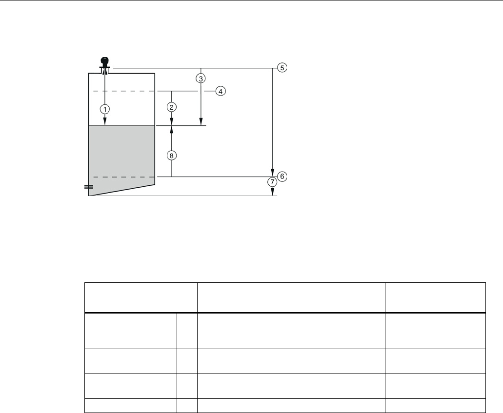
Parameter reference
SITRANS LR250 (mA/HART)
130 Operating Instructions, 08/2014, A5E32220602-AC
Sensor Mode (2.2.2.)
①
Sensor value
⑤
Sensor reference point [see Dimension
drawings] (Page 209)
②
Space
⑥
Low Calibration Point
③
Distance
⑦
Far range
④
High Calibration Point
⑧
Level
Mode
Description
Reference point
NO SERVICE Measurement and associated loop current are
not updated, and the device defaults to Fail-
safe mode
a)
.
n/a
LEVEL * Distance to material surface Low Calibration Point
(process empty level)
SPACE Distance to material surface High Calibration Point
(process full level)
DISTANCE
Distance to material surface
Sensor reference point
a) See Material Level (2.5.1.) for more detail.

Parameter reference
SITRANS LR250 (mA/HART)
Operating Instructions, 08/2014, A5E32220602-AC 131
Material (2.2.3.)
Automatically configures the device to operate in the chosen application type, by changing one
or more of the following parameters:
Propagation Factor (2.8.3.)
,
Position Detect (2.8.4.2.)
,
and/or
CLEF Range (2.8.4.4.)
.
Options
*
LIQUID
LIQUID LOW DK
a)
(low dielectric liquid - CLEF algorithm enabled)
Related parameters
Propagation Factor (2.8.3.)
Position Detect (2.8.4.2.)
CLEF Range (2.8.4.4.)
a) dK < 3.0
You can configure each of the related parameters to suit your particular application.
Damping Filter (2.2.4.)
The time constant for the damping filter. The damping filter smooths out the response to a
sudden change in level. This is an exponential filter and the engineering unit is always in
seconds [see Damping (Page 262) for more detail].
Values
Range: 0 to 100.000 s
Default: 10.000 s
Calibration (2.3.)
Note
We recommend using the Quick Start wizard to configure the device.
Low Calibration Pt. (2.3.1.)
Distance from sensor reference point1) to Low Calibration Point. Units are defined in
Units
(2.2.1.)
Values
Range: 0 to 20 m. Default: 20.00 m
Related parameters
Units (2.2.1.)
Far Range (2.8.2.)
1) The point from which level measurement is referenced, see Threaded Horn Antenna with
extension (Page 209), Flanged Horn with extension (Page 214), and Flanged encapsulated
antenna (3"/DN80/80A sizes and larger) (Page 220).

Parameter reference
SITRANS LR250 (mA/HART)
132 Operating Instructions, 08/2014, A5E32220602-AC
High Calibration Pt. (2.3.2.)
Distance from sensor reference point 1) to High Calibration Point. Units are defined in
Units
(2.2.1.).
Values
Range: 0 to 20 m. Default 0.00 m
Related parameters
Units (2.2.1.)
Near Range (2.8.1.)
When setting the High Calibration Point value, note that echoes are ignored within
Near Range
(2.8.1.)
.
1) The value produced by the echo processing which represents the distance from sensor
reference point to the target. [see Threaded Horn Antenna with extension (Page 209), Flanged
Horn with extension (Page 214), and Flanged encapsulated antenna (3"/DN80/80A sizes and
larger) (Page 220)].
Sensor Offset (2.3.3.)
A constant offset that can be added to or subtracted from the sensor value1) to compensate for a
shifted sensor reference point. (For example, when adding a thicker gasket or reducing the
standoff/nozzle height.) The units are defined in
Units (2.2.1.)
.
Values
Range: -100 to 100 m. Default: 0.00 m
Related parameters
Units (2.2.1.)
1) The value produced by the echo processing which represents the distance from sensor
reference point to the target, see
Sensor Mode (2.2.2.)
.

Parameter reference
SITRANS LR250 (mA/HART)
Operating Instructions, 08/2014, A5E32220602-AC 133
Rate (2.4.)
Response Rate (2.4.1.)
Note
Changing Response Rate resets
Fill Rate per Minute (2.4.2.)
,
Empty Rate per Minute
(2.4.3.)
, and
Damping Filter (2.2.4.)
.
Sets the reaction speed of the device to measurement changes.
Response Rate (2.4.1.)
Fill Rate per Minute
(2.4.2.)
Empty Rate per
Minute (2.4.3.)
Damping Filter (2.2.4.)
*
Slow
0.1 m/min (0.32 ft/min)
10 s
Medium
1.0 m/min (3.28 ft/min)
10 s
Fast
10.0 m/min (32.8 ft/min)
0 s
Use a setting just faster than the maximum filling or emptying rate (whichever is faster).
Fill Rate per Minute (2.4.2.)
Defines the maximum rate at which the reported sensor value is allowed to decrease. Allows you
to adjust the SITRANS LR250 response to decreases in the actual material level. Fill Rate is
automatically updated whenever Response Rate is altered.
Options
Range: 0 to 99999 m / min.
Response Rate (2.4.1.)
Fill Rate per Minute (2.4.2.)
*
Slow
0.1 m/min (0.32 ft/min)
Medium 1.0 m/min (3.28 ft/min)
Fast
10.0 m/min (32.8 ft/min)
Altered by:
Response Rate (2.4.1.)
Related parameters
Units (2.2.1.)
Enter a value slightly greater than the maximum vessel-filling rate, in units per minute.
Sensor value is the value produced by the echo processing which represents the distance from
sensor reference point to the target. See
Sensor Mode (2.2.2.)
for an illustration.

Parameter reference
SITRANS LR250 (mA/HART)
134 Operating Instructions, 08/2014, A5E32220602-AC
Empty Rate per Minute (2.4.3.)
Defines the maximum rate at which the reported sensor value is allowed to increase. Adjusts the
SITRANS LR250 response to increases in the actual material level. Empty Rate is automatically
updated whenever Response Rate is altered
.
Options
Range: 0 to 99999 m / min.
Response Rate (2.4.1.)
Empty Rate per Minute (2.4.3.)
*
Slow
0.1 m/min (0.32 ft/min)
Medium
1.0 m/min (3.28 ft/min)
Fast
10.0 m/min (32.8 ft/min)
Altered by:
Response Rate (2.4.1.)
Related parameters
Units (2.2.1.)
Enter a value slightly greater than the vessel’s maximum emptying rate, in units per minute.
Sensor value is the value produced by the echo processing which represents the distance from
sensor reference point to the target. See
Sensor Mode (2.2.2.)
for an illustration.
Fail-safe (2.5.)
Note
Default settings in the parameter tables are indicated with an asterisk (*) unless explicitly
stated.

Parameter reference
SITRANS LR250 (mA/HART)
Operating Instructions, 08/2014, A5E32220602-AC 135
Material Level (2.5.1.)
Note
The default setting depends whether your dev
ice is a standard or NAMUR NE 43-compliant
device.
Defines the mA output to use when the Fail-safe timer expires.
STANDARD DEVICE
Options
HI
20.5 mA (max. mA Limit)
LO
3.8 mA (min. mA Limit)
*
HOLD
Last valid reading (default 22.6 mA)
VALUE
User-selected value [defined in Fail-Safe mA Value (2.5.3.)]
NAMUR NE 43-COMPLIANT DEVICE1)
Options
HI
20.5 mA (max. mA Limit)
LO
3.8 mA (min. mA Limit)
HOLD
Last valid reading
* VALUE User-selected value [defined in
Fail-Safe mA Value (2.5.3.)
: default
3.58 mA]
1) Orderable option
LOE Timer (2.5.2.)
Note
When a Loss of Echo occurs Material Level (2.5.1.)
determines the material level to be
reported when the Fail
-safe timer expires. See Loss of Echo (LOE) (Page 264)
for more
detail.
Sets the time to elapse since the last valid reading, before the Fail-safe Level is reported.
Values
Range: 0.00 to 7200 seconds
Default: 100 s
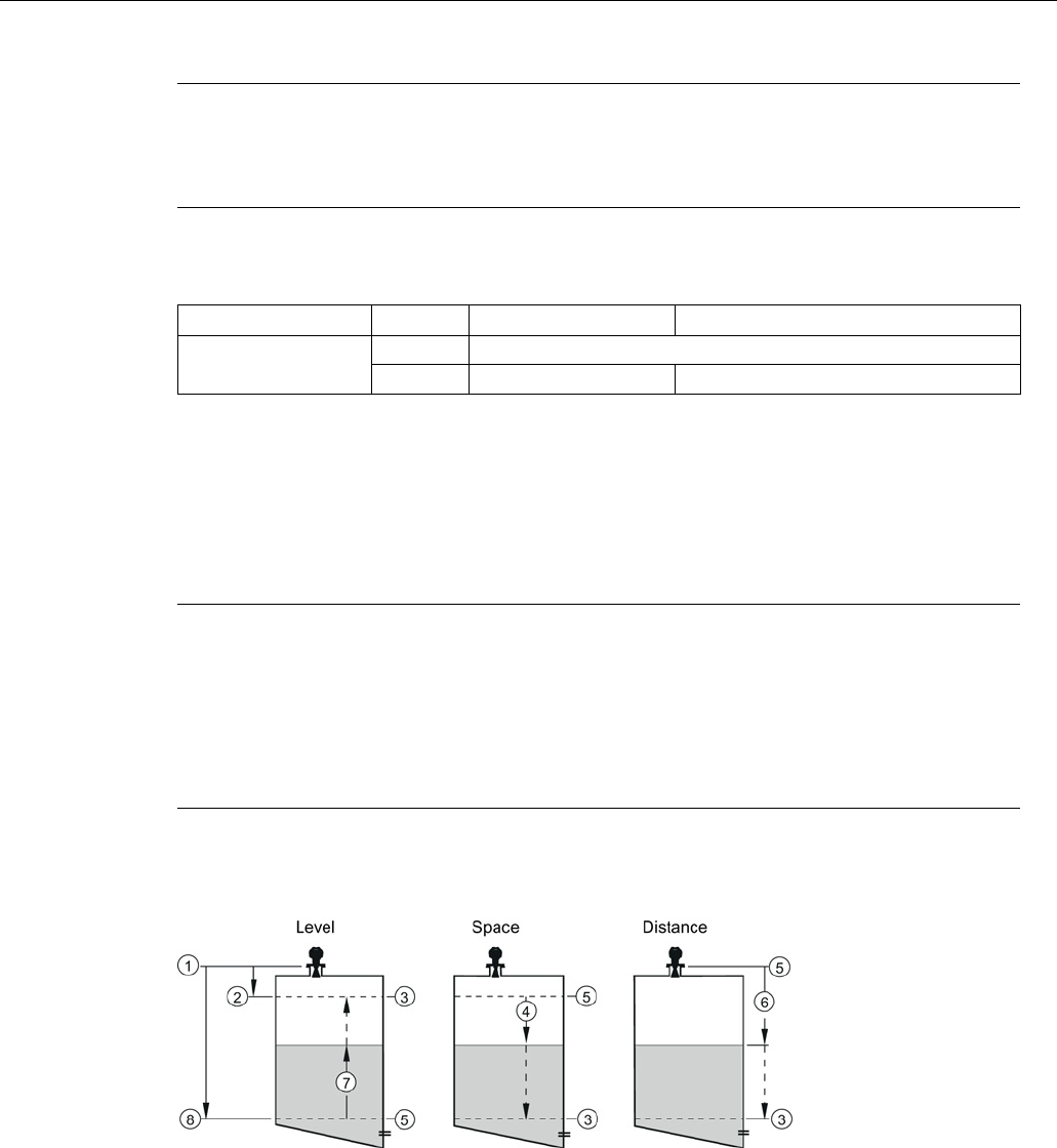
Parameter reference
SITRANS LR250 (mA/HART)
136 Operating Instructions, 08/2014, A5E32220602-AC
Fail-Safe mA Value (2.5.3.)
Note
•
The default settings are dependent on standard or NAMUR NE 43-compliant device.
•
Material Level (2.5.1.)
must be set to
VALUE
to enable the Fail-Safe mA Value to be
reported.
Allows the user to define the mA value to be reported when the Fail-safe timer expires.
Device Type
STANDARD
NAMUR NE43- COMPLIANT
Values
Range
3.56 mA to 22.6 mA
Default
22.60 mA
3.58 mA
Analog Output Scaling (2.6.)
Current Output Function (2.6.1.)
Note
•
Level
,
space
, and
distance
, have different reference points.
•
Use caution when changing Current Output Function while the device is connected to a
HART network. Current Output Function controls the primary value and the loop current
for the device.
•
Current Output Function also affects the secondary, tertiary and quaternary variables in a
HART network.
Can be set to either
Level, Space, Distance,
or
Volume
. (The device can carry out a volume
calculation only after a vessel shape has been specified.)
①
Sensor reference point
⑤
4 mA 0%
②
High calibration point
⑥
Distance
③
20 mA 100%
⑦
Level
④
Space
⑧
Low calibration point

Parameter reference
SITRANS LR250 (mA/HART)
Operating Instructions, 08/2014, A5E32220602-AC 137
Options
Reference point
Description
*
Level
Low Calibration Point
measured as a percentage of the
difference between High Calibration
Point and Low Calibration Point
Space
High Calibration Point
Distance
Sensor reference point measured as a percentage of Low
Calibration Point
Volume
converts a level measurement to a volume output
Manual
a)
(LUI only)
allows
mA
Output Value (2.6.6.)
to be set to a user-defined value
a)
Current Output Function must be set to
Manual
before modifying
mA Output Value (2.6.6.).
Remember to restore the previous Current Output Function setting after modifying mA Output
Value.
To view the mA reading in the secondary region of the LCD, press on the handheld
programmer.
To modify Current Output Function via SIMATIC PDM:
● Open the menu
Device – Select Analog Output
. See Select Analog Output via SIMATIC PDM
(Page 97) for more detail.

Parameter reference
SITRANS LR250 (mA/HART)
138 Operating Instructions, 08/2014, A5E32220602-AC
4 mA Setpoint (2.6.2.)
Sets the process level corresponding to the 4 mA value. 4 mA always defaults to
0
, and
Current
Output Function (2.6.1.)
determines whether this is a Level, Space, Distance, or Volume
measurement. (See
Current Output Function (2.6.1.)
for an illustration.)
Values
Range: –999999 to +999999 (limits vary with current function and units)
Default:
0.00
m (set to value corresponding to 0% as defined by Current
Output Function)
Related Parameters
Units (2.2.1.)
Current Output Function (2.6.1.)
● Enter the reading that is to correspond to a 4 mA output.
● Units are defined in
Units (2.2.1.)
for Level, Space, or Distance. Units are unspecified for
Volume.
20 mA Setpoint (2.6.3.)
Sets the process level corresponding to the 20 mA value. 20 mA always defaults to 100%, and
Current Output Function (2.6.1.)
determines whether this is a Level, Space, or Distance
measurement. (See
Current Output Function (2.6.1.)
for an illustration.)
Values
Range: –999999 to +999999 (limits vary with current function and units)
Default:
20.00
m (set to value corresponding to 100% as defined by Current
Output Function)
Related Parameters
Units (2.2.1.)
Current Output Function (2.6.1.)
● Enter the reading that is to correspond to a 20 mA output.
● Units are defined in
Units (2.2.1.)
for Level, Space, or Distance. Units are unspecified for
Volume.
Minimum mA limit (2.6.4.)
Prevents the mA output from dropping below this minimum level for a measurement value. This
does not restrict the Fail-safe or Manual settings.
Values
Range: 3.8 to 20.5 (mA)
Default: 3.8 (mA)

Parameter reference
SITRANS LR250 (mA/HART)
Operating Instructions, 08/2014, A5E32220602-AC 139
Maximum mA limit (2.6.5.)
Prevents the mA output from rising above this maximum level for a measurement value. This
does not restrict the Fail-safe or Manual settings.
Values
Range: 3.8 to 20.50 (mA)
Default: 20.50 (mA)
mA Output Value (2.6.6.)
Allows you to use a simulated value to test the functioning of the loop. You can enter 4 mA, 20
mA, or any other user-defined value within the range.
Values
Range: 3.56 mA to 22.6 mA
Read Only unless Current Output Function (2.6.1.) is set to Manual.
Related parameter
Current Output Function (2.6.1.)
1. First set
Current Output Function (2.6.1.)
to
Manual.
2. Enter the desired mA value in mA Output Value.
3. After completing the test, remember to reset
Current Output Function (2.6.1.)
to the previous
setting.
Via SIMATIC PDM:
Open the menu Device – Loop Test. For more detail, see Loop Test (Page 97).
Linearization (2.7.)
Volume (2.7.1.)
Carries out a volume conversion from a level value.
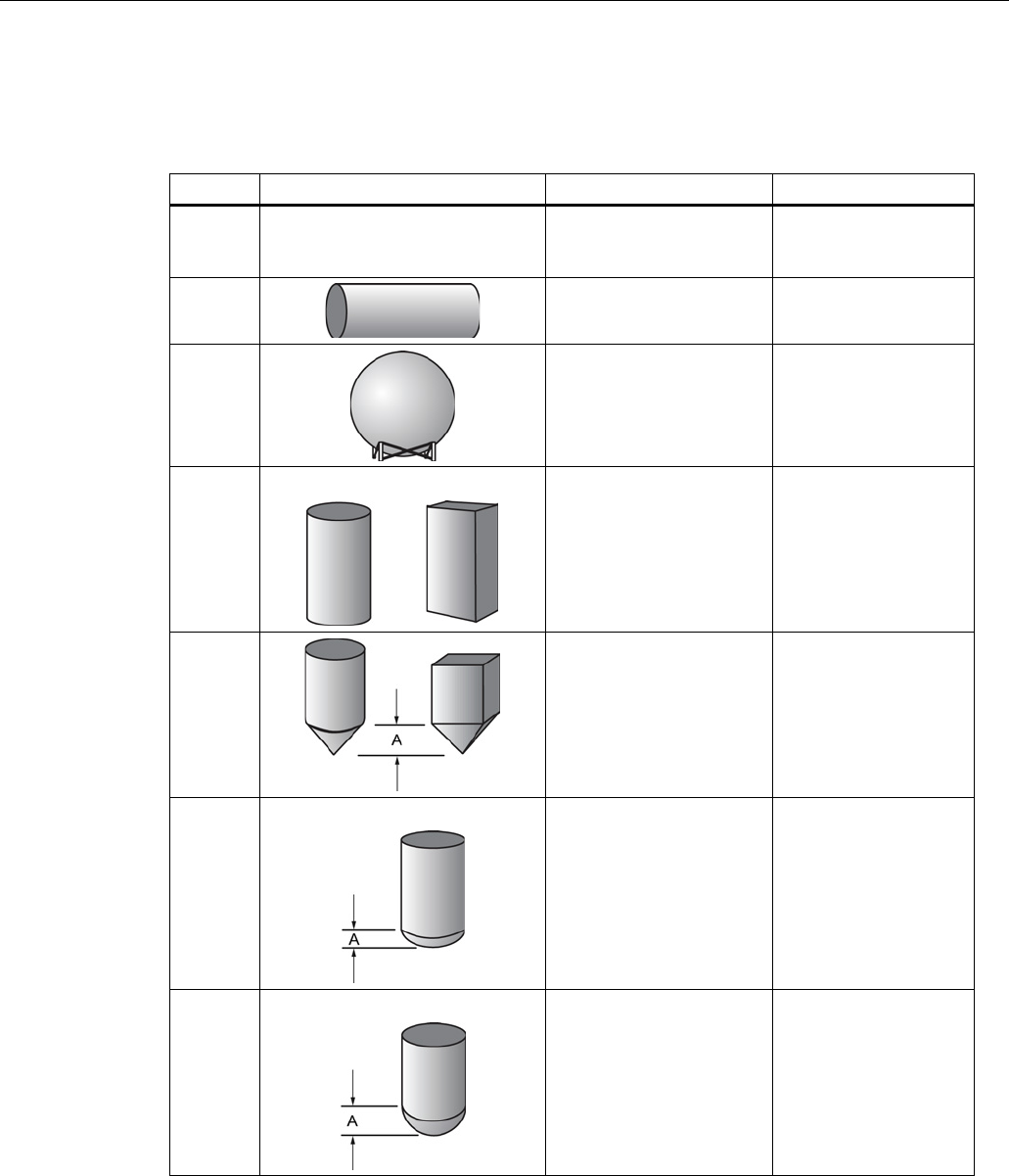
Parameter reference
SITRANS LR250 (mA/HART)
140 Operating Instructions, 08/2014, A5E32220602-AC
Vessel Shape (2.7.1.1.)
Defines the vessel shape and allows the LR250 to calculate volume instead of level. If
None
is
selected, no volume conversion is performed. Select the vessel shape matching the monitored
vessel or reservoir.
Vessel Shape
LCD DISPLAY/ Description
Also required
* None NONE/
No volume calculation
required
N/A
CYLINDER/
Flat end horizontal cylinder Maximum volume
SPHERE/
Sphere Maximum volume
LINEAR/
Upright, linear (flat bottom) Maximum volume
CONICAL BOT/
Conical or pyramidal
bottom
Maximum volume,
dimension A
PARABOLIC
BOT/Parabolic bottom Maximum volume,
dimension A
HALF SPHERE BOT/
Half-sphere bottom Maximum volume,
dimension A
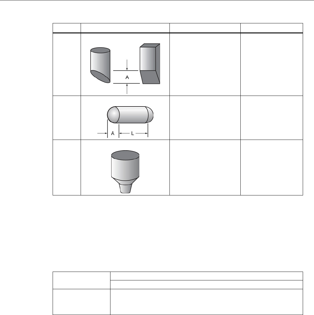
Parameter reference
SITRANS LR250 (mA/HART)
Operating Instructions, 08/2014, A5E32220602-AC 141
Vessel Shape
LCD DISPLAY/ Description
Also required
FLAT SLOPED BOT/
Flat sloped bottom Maximum volume,
dimension A
PARABOLIC ENDS/
Parabolic end horizontal
cylinder
Maximum volume,
dimension A, dimension
L
LINEAR TABLE a) /
Linearization table
(level/volume breakpoints)
Maximum volume,
tables 1-32 level and
volume breakpoints
a)
Linearization Table must be selected in order for level/volume values [see
Table 1-8 (2.7.2.)
] to be
transferred.
Maximum Volume (2.7.1.2.)
The maximum volume of the vessel. Enter the vessel volume corresponding to High Calibration
Point. For example, if your maximum vessel volume is 8000 L, enter a value of 8000. Volume
units are defined by the user but are not explicitly stated or shown in the SITRANS LR250.
Values
Range: 0.0 to 99999 m
Default: 100.0
Related Parameters
Low Calibration Pt. (2.3.1.)
High Calibration Pt. (2.3.2.)
Vessel Shape (2.7.1.1.)

Parameter reference
SITRANS LR250 (mA/HART)
142 Operating Instructions, 08/2014, A5E32220602-AC
Vessel Dimension A (2.7.1.3.)
The height of the vessel bottom when the bottom is conical, pyramidal, parabolic, spherical, or
flat -sloped. If the vessel is horizontal with parabolic ends, the depth of the end. See
Vessel
Shape (2.7.1.1.)
for an illustration.
Values
Range: 0.0 to 99.999 m
Default: 0.0
Related Parameters
Units (2.2.1.)
Vessel Shape (2.7.1.1.)
Vessel Dimension L (2.7.1.4.)
Length of the cylindrical section of a horizontal parabolic end vessel. See
Vessel Shape
(2.7.1.1.)
for an illustration.
Values
Range: 0.0 to 99.99 m
Default: 0.0
Related Parameters
Units (2.2.1.)
Vessel Shape (2.7.1.1.)

Parameter reference
SITRANS LR250 (mA/HART)
Operating Instructions, 08/2014, A5E32220602-AC 143
Table 1-8 (2.7.2.)
Note
Linearization Table must be selected in Vessel Shape (2.7.1.1.)
in order for level/volume
values to be transferred.
If your vessel shape is more complex than any of the preconfigured shapes, you can define the
shape as a series of segments. A value is assigned to each level breakpoint and a
corresponding value is assigned to each volume breakpoint. Level values are defined in
Units
(2.2.1.).
Volume units are defined by the user but are not explicitly stated in the SITRANS
LR250.
Level Values
Range:
0.0
to
span
Span = High Calibration Pt. (2.3.2.) - Low Calibration Pt. (2.3.1.)
Default: 0.0
Volume Values
Range:
0.0
to
Maximum Volume (2.7.1.2.)
Default: 0.0
Enter up to 32 level breakpoints, where the corresponding volume is known. The values
corresponding to 100% and 0% levels must be entered. The breakpoints can be ordered from
top to bottom, or the reverse.
Breakpoints are grouped into four tables: Table 1-8, Table 9-16, Table 17-24, and Table 25-32.
Entering breakpoints via the handheld programmer:
1. The default unit for level values is
m:
to change it navigate to
Setup (2.) > Sensor (2.2.) >
Units(2.2.1.)
,
and select the desired unit.
2. Navigate to
Setup (2.) > Linearization (2.7.) > Maximum Volume (2.7.1.2.)
, and enter the
value.
3. Go to the appropriate table for the particular breakpoint you wish to adjust: for example, go to
Table 1-8 for breakpoint 1.
4. Under Table 1-8, go to
Level 1 (2.7.2.1.)
to enter the level value for the breakpoint 1.
5. Under Table 1-8, go to
Volume 1 (2.7.2.2.)
to enter the volume value for the breakpoint 1.
6. Repeat steps 3 to 5, until values have been entered for all required breakpoints.
Level 1 (2.7.2.1.)
1. Press
RIGHT arrow
to open Edit mode.
2. Enter level value and press
RIGHT arrow
to except it.
3. Press
DOWN arrow
to move to corresponding volume breakpoint.
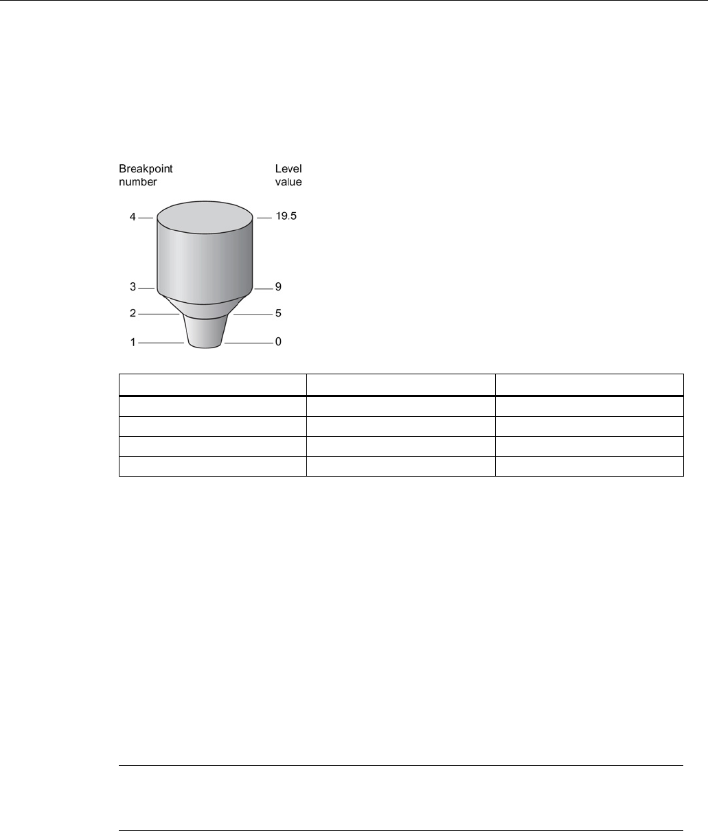
Parameter reference
SITRANS LR250 (mA/HART)
144 Operating Instructions, 08/2014, A5E32220602-AC
Volume 1 (2.7.2.2.)
1. Press
RIGHT arrow
to open Edit mode.
2. Enter volume value and press
RIGHT arrow
to accept it.
3. Press
DOWN arrow
to move to next level breakpoint.
Example
(values are for example purposes only)
Breakpoint Number
Level value (m)
Volume value (l)
1
0
0
2
5
500
3
9
3000
4
19.5
8000
Table 9-16 (2.7.3.)
Table 17-24 (2.7.4.)
Table 25-32 (2.7.5.)
Signal Processing (2.8.)
Note
Default settings in the parameter tables are indicated with an asterisk (*) unless explicitly
stated.

Parameter reference
SITRANS LR250 (mA/HART)
Operating Instructions, 08/2014, A5E32220602-AC 145
Near Range (2.8.1.)
The range in front of the device (measured from the sensor reference point) within which any
echoes will be ignored. This is sometimes referred to as blanking or a dead zone. The factory
setting is 50 mm (2") past the end of the antenna, and the default is dependent on the antenna
type and process connection. [See Dimension drawings (Page 209) for antenna heights.]
Values
Range: 0 to 20 m (0 to 65.6 ft)
Default depends on antenna type and process connection:
Related parameters
Units (2.2.1.)
Far Range (2.8.2.)
Note
Far Range can extend beyond the bottom of the vessel.
Allows the material level to drop below Low Calibration Point without generating a Loss of Echo
(LOE) state. See
Sensor Mode (2.2.2.)
for an illustration.
Values
Range: Min. =
Low Calibration Pt.
Max. =
23
m (75.45 ft)
Default: Value for Low Calibration Pt. + 1 m (3.28 ft)
Related parameters
Units (2.2.1.)
Use this feature if the measured surface can drop below the Low Cal. Point in normal operation.
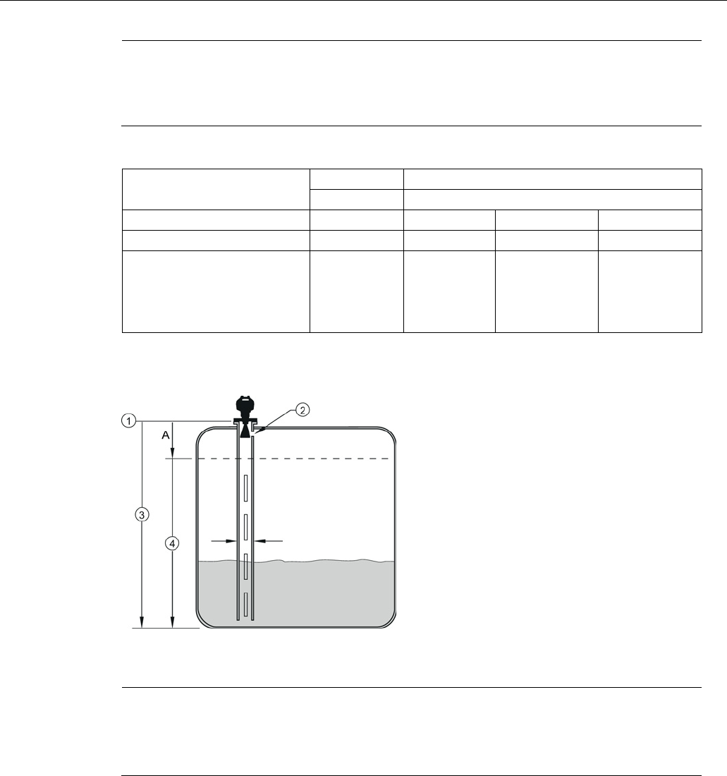
Parameter reference
SITRANS LR250 (mA/HART)
146 Operating Instructions, 08/2014, A5E32220602-AC
Propogation Factor (2.8.3.)
Note
•
When operating in a stillpipe, values for
CLEF Range (2.8.4.4.)
, and for the propagation
factor, should be set according to the pipe size. See the table below.
•
For reliable results the antenna size must be close to the pipe size.
Compensates for the change in microwave velocity due to propagation within a metal stillpipe
instead of in free space.
Values
Range
0.3 to 1.0 depending on pipe size
Default
1.0000
Nominal Pipe Size
a)
40 mm (1.5")
50 mm (2")
80 mm (3")
100 mm (4")
Propagation Factor
0.9844
0.988
0.9935
0.9965
CLEF Range (2.8.4.4.) settings
Low
calibration
point -
700 mm
(2.29 ft)
b)
Low
calibration
point -
700 mm
(2.29 ft)
b)
Low calibration
point -1000 mm
(3.28 ft)b)
Low calibration
point -1000 mm
(3.28 ft)b)
a)
Since pipe dimensions may vary slightly, the propagation factor may also vary.
b)
CLEF range covers the whole measurement range except first 700 or 1000 mm from unit
reference point (see A in graphic below)
①
sensor reference point
③
low calibration point
②
air gap
④
CLEF range 2.8.4.4.
A
700 or 1000 mm
Note
Flanged encapsulated antenna
For Flanged encapsulated antenna (7ML5432) match the process connection size to the
pipe diameter whenever possible (for example, mount a DN80
/3" flange on DN80/3" pipe).
Parameter reference
SITRANS LR250 (mA/HART)
Operating Instructions, 08/2014, A5E32220602-AC 147
Echo Select (2.8.4.)
Algorithm (2.8.4.1.)
Selects the algorithm to be applied to the echo profile to extract the true echo.
Options
*
tF
True First echo
L
Largest echo
BLF
Best of Largest and First echo
Position Detect (2.8.4.2.)
Defines where on the echo the distance measurement is determined.
Options
Center
*
Hybrid (Center and CLEF)
CLEF (Constrained Leading Edge Fit)
Related parameters
CLEF Range (2.8.4.4.)
If the vessel bottom is being reported as the level instead of the actual material level (at low level
conditions), or if the dielectric constant of the liquid to be monitored is less than 3, we
recommend setting Position Detect to Hybrid and
CLEF Range (2.8.4.4.)
to 0.5 m (1.64 ft).
Echo Threshold (2.8.4.3.)
Sets the minimum echo confidence that the echo must meet in order to prevent a Loss of Echo
condition and the expiration of the Fail-safe (LOE) timer. When
Confidence (2.8.6.1.)
exceeds
Echo Threshold (2.8.4.3.)
, the echo is accepted as a valid echo and is evaluated.
Values
Range: 0 to 99
Default: 5
Related Parameters
LOE Timer (2.5.2.)
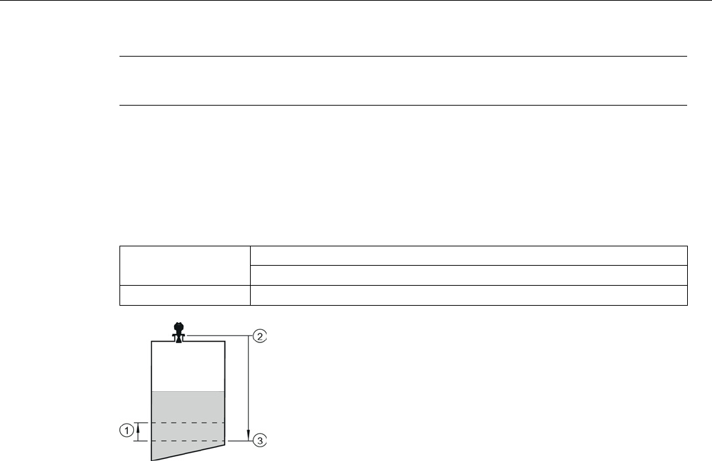
Parameter reference
SITRANS LR250 (mA/HART)
148 Operating Instructions, 08/2014, A5E32220602-AC
CLEF Range (2.8.4.4.)
Note
CLEF Range is referenced from Far range.
The CLEF algorithm is used mainly to allow correct level reporting for low dK materials which
may otherwise cause an incorrect reading in an empty or almost empty vessel.
It is used from Low Calibration Point (process empty level ) up to the level defined by CLEF
Range (see illustration below). Above that point the Center algorithm is used. For more detail
see CLEF Range (Page 258).
Values
Range: 0 to 20 m (0 to 65.6 ft)
Default: 0.0 m
Related parameters
Position Detect (2.8.4.2.)
①
CLEF Range
②
Sensor reference point
③
Low Calibration Point (process empty level )
In applications with low dK materials we recommend setting CLEF Range to 0.5 m (1.64 ft) and
Position Detect (2.8.4.2.)
to Hybrid.
Sampling (2.8.5.)
Provides a method of checking the reliability of a new echo before accepting it as the valid
reading, based on numbers of samples above or below the currently selected echo.

Parameter reference
SITRANS LR250 (mA/HART)
Operating Instructions, 08/2014, A5E32220602-AC 149
Echo Lock (2.8.5.1.)
Note
Ensure the agitator is always running while SITRANS LR250 is monitori
ng the vessel, to
avoid stationary blade detection.
Selects the measurement verification process.
Options
Lock Off
Maximum Verification (not recommended for radar)
*
Material Agitator
Total Lock (not recommended for radar)
Related parameters
Fill Rate per Minute (2.4.2.)
Empty rate per Minute (2.4.3.)
Sampling Up (2.8.5.2.)
Sampling Down (2.8.5.3.)
For radar applications, Material Agitator is the most often-used setting, to avoid agitator blade
detection.
Sampling Up (2.8.5.2.)
Specifies the number of consecutive echoes that must appear above the echo currently
selected, before the measurement is accepted as valid.
Values
Range:
1
to
50
Default: 5
Sampling Down (2.8.5.3.)
Specifies the number of consecutive echoes that must appear below the echo currently selected,
before the measurement is accepted as valid.
Values
Range: 1 to 50
Default: 2

Parameter reference
SITRANS LR250 (mA/HART)
150 Operating Instructions, 08/2014, A5E32220602-AC
Echo Quality (2.8.6.)
Confidence (2.8.6.1.)
Indicates echo reliability: higher values represent better echo quality. The display shows the
echo confidence of the last measurement.
Echo Threshold (2.8.4.3.)
defines the minimum
criterion for echo confidence.
Values
(view only)
0 to 99
----
Shot not used
Related Parameters
Echo Threshold (2.8.4.3.)
Open the menu
Device – Echo Profile Utilities
and click on the tab
Echo Profile
.
Echo Strength (2.8.6.2.)
Displays the absolute strength (in dB above 1 μV rms) of the echo selected as the measurement
echo.
Values
(view only)
-20 to 99
----
Shot not used
Open the menu
Device – Echo Profile Utilities
and click on the tab
Echo Profile
.
Noise Average (2.8.6.3.)
Displays the average ambient noise (in dB above 1 μV rms) of a noise profile. Noise level is a
combination of transient noise and receiving circuitry. After a measurement, the values from the
previous noise shot will be displayed.
TVT Setup (2.8.7.)
Note
Default settings in the parameter tables are indicated with an asterisk (*) unless explicitly
stated.

Parameter reference
SITRANS LR250 (mA/HART)
Operating Instructions, 08/2014, A5E32220602-AC 151
Auto False Echo Suppression (2.8.7.1.)
Used together with
Auto False Echo Suppression Range (2.8.7.2.)
to screen out false echoes in
a vessel with known obstructions. A ’learned TVT’ (time varying threshold) replaces the default
TVT over a specified range. See
Auto False Echo Suppression (Page 259)
for a more detailed
explanation.
Note
•
Make sure material level is below all known obstructions when Auto False Echo
Suppression is used to learn the echo profile. (An empty or almost empty vessel is
recommended.)
•
Note the distance to material level when Auto False Echo learns the environment. Set
Auto False Echo Suppression Range to a shorter distance to avoid the material echo
being screened out.
•
Set Auto False Echo Suppression and Auto False Echo Suppression Range during
startup, if possible.
•
If the vessel contains an agitator it should be running.
•
Before adjusting these parameters, rotate the instrument for best signal (lower false-
echo
amplitude).
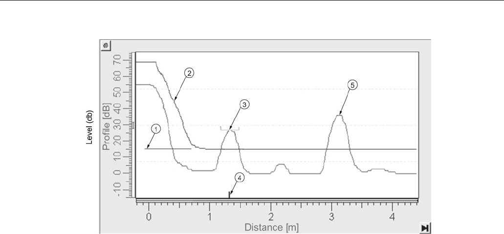
Parameter reference
SITRANS LR250 (mA/HART)
152 Operating Instructions, 08/2014, A5E32220602-AC
Before Auto False Echo Suppression
①
TVT Hover Level
④
echo marker
②
default TVT
⑤
material level
③
false echo
1. Determine Auto False Echo Suppression Range. Measure the actual distance from the
sensor reference point to the material surface using a rope or tape measure.
2. Subtract 0.5 m (20") from this distance, and use the resulting value.
3. Go to
Auto False Echo Suppression Range (2.8.7.2.)
and enter the value calculated in
step 2.
4. Go to
Auto False Echo Suppression (2.8.7.1.)
and press RIGHT arrow to open Edit Mode.
5. Select
Learn
. The device will automatically revert to
On
(Use Learned TVT) after a few
seconds.
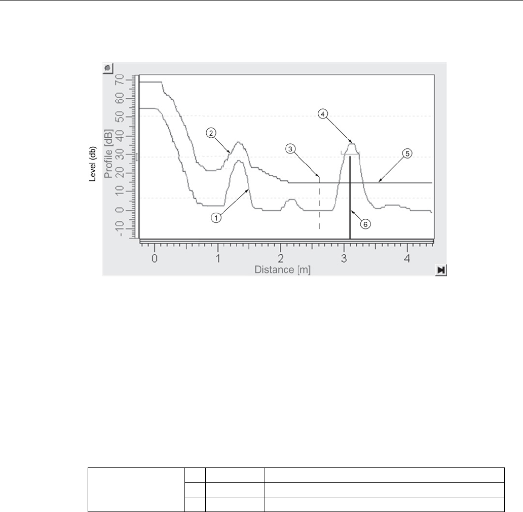
Parameter reference
SITRANS LR250 (mA/HART)
Operating Instructions, 08/2014, A5E32220602-AC 153
After Auto False Echo Suppression
①
false echo
④
material level
②
learned TVT
⑤
default TVT
③
Auto False
Echo Suppression
Range
⑥
echo marker
To set Auto False Echo Suppression via SIMATIC PDM:
Open the menu
Device – Echo Profile Utilities
and click on the tab
Auto False Echo
Suppression
. For more detailed instructions see Auto False Echo Suppression via SIMATIC
PDM (Page 92).
To set Auto False Echo Suppression via the handheld programmer:
Options
OFF
Default TVT will be used.
* ON ’Learned’ TVT will be used.
LEARN
’Learn’ the TVT
a)
.
a) The learned TVT takes effect only at the next measurement.

Parameter reference
SITRANS LR250 (mA/HART)
154 Operating Instructions, 08/2014, A5E32220602-AC
Auto False Echo Suppression Range (2.8.7.2.)
Note
Changes take effect only at the next measurement. "Master reset" does not clear the
learned/sto
red TVT, select "Off" to turn it off or "learn" for a new TVT. See
Master Reset
(4.1.)
Specifies the range within which Learned TVT is used [see
Auto False Echo Suppression
(2.8.7.1.)
for more detail].
Values
Range: 0.00 to 20.00 m
Default: 1.00 m
Related parameters
Units (2.2.1.)
1. Calculate range according to
Auto False Echo Suppression (2.8.7.1.)
steps 1 and 2.
2. Press
RIGHT arrow
to open Edit mode.
3. Enter the new value and press
RIGHT arrow
to accept it.
4. Set
Auto False Echo Suppression (2.8.7.1.)
.
Hover Level (2.8.7.3.)
Note
Changes take effect only at the next measurement.
Defines how high the TVT (Time Varying Threshold) is placed above the noise floor of the echo
profile, as a percentage of the difference between the peak of the largest echo in the profile and
the noise floor. See
Auto False Echo Suppression (2.8.7.1.)
for an illustration.
Values
Range:
0
to
100
%
Default: 40%
When the device is located in the center of the vessel, the TVT hover level may be lowered to
increase the confidence level of the largest echo.
Shaper Mode (2.8.7.4.)
Enables/disables the TVT shaper.
Options
ON
*
OFF

Parameter reference
SITRANS LR250 (mA/HART)
Operating Instructions, 08/2014, A5E32220602-AC 155
TVT shaper (2.8.8.)
Note
•
The range is –100 to 100 bits. With 2 bits per dB this gives a range of –50 to 50 dB.
•
Shaper Mode (2.8.7.4.)
must be turned ON in order for TVT shaper points to be
transferred.
Adjusts the TVT (Time Varying Threshold) at a specified range (breakpoint on the TVT). This
allows you to reshape the TVT to avoid unwanted echoes. There are 40 breakpoints arranged in
5 groups. (We recommend using SIMATIC PDM to access this feature.)
To use TVT shaper via SIMATIC PDM:
1. Go to
Level Meter > Setup > Signal Processing > TVT setup > Shaper Mode
and select
On
.
2. Open the menu
Device – Echo Profile Utilities
and click on
TVT Shaper
. For more detail see
TVT shaper via SIMATIC PDM (Page 91).
To use TVT shaper via LUI (local user interface):
1. Go to
Shaper Mode (2.8.7.4.)
and select
On
.
2. Go to Breakpoint
1-9 (2.8.8.1.)
.
3. Open Shaper 1 and enter the TVT Offset value (between –50 and 50).
4. Go to the next Shaper point and repeat steps 3 and 4 until all desired breakpoint values have
been entered.
Breakpoint 1-9 (2.8.8.1.)
Values
Range: –50 to 50 dB
Default: 0 dB
Breakpoint 10-18 (2.8.8.2.)
Values
Range: –50 to 50 dB
Default: 0 dB
Breakpoint 19-27 (2.8.8.3.)
Values
Range: –50 to 50 dB
Default: 0 dB

Parameter reference
SITRANS LR250 (mA/HART)
156 Operating Instructions, 08/2014, A5E32220602-AC
Breakpoint 28-36 (2.8.8.4.)
Values
Range: –50 to 50 dB
Default: 0 dB
Breakpoint 37-40 (2.8.8.5.)
Values
Range: –50 to 50 dB
Default: 0 dB
Measured Values (2.8.9.)
Read only. Allows you to view measured values for diagnostic purposes.
To access measured values via SIMATIC PDM:
Open the menu
View – Process Variables
.
Level Measurement (2.8.9.1.)
The value for level.
Space Measurement (2.8.9.2.)
The value for space.
Distance Measurement (2.8.9.3.)
The value for distance.
Volume Measurement (2.8.9.4.)
The value for volume.
Diagnostics (3.)
Echo Profile (3.1.)
Allows you to request the current echo profile either locally via the handheld programmer, or
remotely via SIMATIC PDM, or AMS Device Manager. [For more detail see Echo Processing
(Page 254)].

Parameter reference
SITRANS LR250 (mA/HART)
Operating Instructions, 08/2014, A5E32220602-AC 157
To request a profile via SIMATIC PDM:
Open the menu
Device – Echo Profile Utilities
. [For more detail see Echo Profile Utilities via
SIMATIC PDM (Page 88)].
To request a profile via the handheld programmer:
1. In
PROGRAM
mode, navigate to
Level Meter > Diagnostics (3.) > Echo Profile (3.1.)
2. Press
RIGHT arrow
to request a profile.
[For more detail see Requesting an Echo Profile (Page 69)].
Electronics Temperature (3.2.)
Current Internal Temperature (3.2.1.)
Read only. Displays (in degrees C) the current temperature on the circuit board recorded by the
internal electronics.
For access via SIMATIC PDM open the menu
View – Process Variables
and check the field
Electronics Temperature
.
Highest Value (3.2.2.)
Read only. Displays (in degrees C) the maximum temperature recorded by the internal
electronics. The high and low values are maintained over a power cycle.
Via SIMATIC PDM navigate to
Maintenance and
Diagnostics > Electronics Temperature
.
Lowest Value (3.2.3.)
Read only. Displays (in degrees C) the minimum temperature recorded by the internal
electronics. The high and low values are maintained over a power cycle.
Via SIMATIC PDM navigate to
Maintenance and Diagnostics > Electronics Temperature
.
Service (4.)
Note
Default settings
in the parameter tables are indicated with an asterisk (*) unless explicitly
stated.

Parameter reference
SITRANS LR250 (mA/HART)
158 Operating Instructions, 08/2014, A5E32220602-AC
Master Reset (4.1.)
Note
Fol
lowing a reset to
Factory Defaults
, complete reprogramming is required.
Resets all parameter to factory defaults, with the following exceptions:
●
Device Address (5.1.)
remains unchanged if the reset command is sent remotely (via AMS,
PDM, DTM, FC375) but is reset to 0 if the reset command is sent via LUI.
●
Write Protect (6.2.1.)
and
PIN to Unlock (6.2.2.)
values are not reset.
●
Auto False Echo Suppression (2.8.7.1.)
learned TVT and
Auto False Echo Suppression
Range (2.8.7.2.)
are not lost.
Options
*
Idle or Done (Return to previous menu)
Factory Defaults
To perform a reset to factory defaults via SIMATIC PDM, open the menu
Device – Master Reset
and click on
Factory Defaults.

Parameter reference
SITRANS LR250 (mA/HART)
Operating Instructions, 08/2014, A5E32220602-AC 159
Remaining Device Lifetime (4.2.)
Note
•
Default settings in the parameter tables are indicated with an asterisk (*) unless explicitly
stated.
•
Four sets of parameters allow you to monitor the Device/Sensor Lifetimes and set up
Maintenance/Service schedules, based on operating hours instead of a calendar-based
schedule. See also
Remaining Sensor Lifetime (4.3.)
,
Service Schedule (4.4.)
, and
Calibration Schedule (4.5.)
.
•
Performing a reset to
Factory Defaults
will reset all the Maintenance Schedule
parameters to their factory defaults.
•
The device operates in years. To view Remaining Device Lifetime parameters in hours or
days (via SIMATIC PDM only) see
Lifetime (Expected) (4.2.1.)
.
The device tracks itself based on operating hours and monitors its predicted lifetime. You can
modify the expected device lifetime, set up schedules for maintenance reminders, and
acknowledge them.
The maintenance warnings and reminders are available through HART communications. This
information can be integrated into an Asset Management system. For optimal use, we
recommend that you use SIMATIC PCS7 Asset Management Software in conjunction with
SIMATIC PDM.
To access these parameters via SIMATIC PDM:
● Open the menu
Device – Maintenance
and select the
Remaining Device Lifetime
tab.
● After modifying values/units as required, click on
Write
to accept the change, and
Read
to
view the effect of the change.
● Click on
Snooze
to add a year to the Total Expected Device Life.
Time Units
Options
a)
Hours; days; years
Default: years
a) Selectable only via SIMATIC PDM.
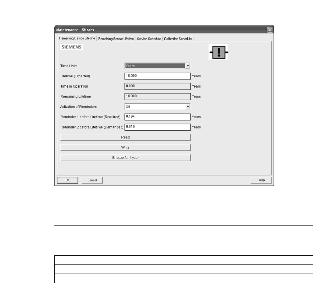
Parameter reference
SITRANS LR250 (mA/HART)
160 Operating Instructions, 08/2014, A5E32220602-AC
Lifetime (Expected) (4.2.1.)
Note
The device always operates in ye
ars. Changing the units affects only the parameter view of
the Service Interval parameters in SIMATIC PDM.
User-configurable recommended time between product inspections.
Values
Units
a)
: hours, days, years
Range: 0 to 20 years
Default: 10 years
a) Units are selectable only via SIMATIC PDM.
Time in Operation (4.2.2.)
Read only. The amount of time the device has been operating.
Remaining Lifetime (4.2.3.)
Read only.
Lifetime (Expected) (4.2.1.)
less
Time in Operation (4.2.2.).

Parameter reference
SITRANS LR250 (mA/HART)
Operating Instructions, 08/2014, A5E32220602-AC 161
Activation of Reminders (4.2.4.)
Note
To modify this parameter via SIMATIC PDM it must be accessed via the pull
-down menu
Device – Maintenance
.
Allows you to enable a maintenance reminder.
Values
*
Timer OFF
ON - no reminders checked
ON - Reminder 1 (Maintenance Required) checked
ON - Reminders 1 and 2 checked
ON - Reminder 2 (Maintenance Demanded) checked
1. First set the values in
Reminder 1 before Lifetime (Required) (4.2.5.)
/
Reminder 2 before
Lifetime (Demanded) (4.2.6.)
.
2. Select the desired
Activation of Reminders
option.
Reminder 1 before Lifetime (Required) (4.2.5.)
If
Remaining Lifetime (4.2.3.)
is equal to or less than this value, the device generates a
Maintenance Required reminder.
Values
Range: 0 to Lifetime (Expected) (4.2.1.)
Default: 0.164 years
1. Modify values as required.
2. Set
Activation of Reminders (4.2.4.)
to the desired option.
Reminder 2 before Lifetime (Demanded) (4.2.6.)
If
Remaining Lifetime (4.2.3.)
is equal to or less than this value, the device generates a
Maintenance Demanded reminder.
Values
Range: 0 to Lifetime (Expected) (4.2.1.)
Default: 0.019 years
1. Modify values as required.
2. Set
Activation of Reminders (4.2.4.)
to the desired option.

Parameter reference
SITRANS LR250 (mA/HART)
162 Operating Instructions, 08/2014, A5E32220602-AC
Maintenance Status (4.2.7.)
Indicates which level of maintenance reminder is active.
In SIMATIC PDM, open the menu
View – Device Status
, click on the
Maintenance
tab, and
check the
Device Lifetime Status
window.
Acknowledge Status (4.2.8.)
Indicates which level of maintenance reminder has been acknowledged.
In SIMATIC PDM, open the menu
View – Device Status
, click on the
Maintenance
tab, and
check the
Device Lifetime Status
window.
Acknowledge (4.2.9.)
Acknowledges the current maintenance reminder.
To acknowledge a reminder via SIMATIC PDM:
1. Open the menu
View – Device Status
and click on the
Maintenance
tab.
2. In the
Device Lifetime
section, click on
Acknowledge Warnings
.
To acknowledge a reminder via the handheld programmer:
1. Press
RIGHT arrow
twice to open parameter view and activate Edit Mode.
2. Press
RIGHT arrow
to acknowledge the reminder.

Parameter reference
SITRANS LR250 (mA/HART)
Operating Instructions, 08/2014, A5E32220602-AC 163
Remaining Sensor Lifetime (4.3.)
Note
•
Default settings in the parameter tables are indicated with an asterisk (*) unless explicitly
stated.
•
Four sets of parameters allow you to monitor the Device/Sensor Lifetimes and set up
Maintenance/Service schedules, based on operating hours instead of a calendar-based
schedule. See also
Remaining Device Lifetime (4.2.), Service Schedule (4.4.)
,
and
Calibration Schedule (4.5.)
.
•
Performing a reset to Factory Defaults will reset all the Maintenance Schedule
parameters to their factory defaults.
•
The device operates in years. To view Remaining Sensor Lifetime parameters in hours or
days (via SIMATIC PDM only) see
Lifetime Expected (4.3.1.)
.
The device monitors the predicted lifetime of the sensor (the components exposed to the vessel
environment). You can modify the expected sensor lifetime, set up schedules for maintenance
reminders, and acknowledge them.
To access these parameters via SIMATIC PDM:
● Open the menu
Device – Maintenance
and select the
Remaining Sensor Lifetime
tab.
● After modifying values/units as required, click on
Write
to accept the change, and
Read
to
view the effect of the change.
● Click on
Snooze
to add a year to the Total Expected Sensor Life.
● Click on
Sensor Replaced
to restart the timer and clear any fault messages.
Time Units
Options
a)
Hours; days; years
Default: years
a) Selectable only via SIMATIC PDM.
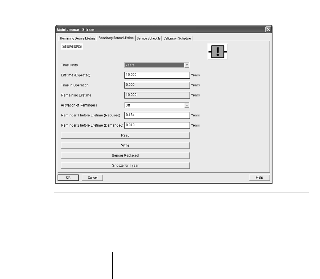
Parameter reference
SITRANS LR250 (mA/HART)
164 Operating Instructions, 08/2014, A5E32220602-AC
Lifetime (Expected) (4.3.1.)
Note
The device always operates in years. Changing the units affects only the parameter view of
Remaining Sensor Life parameters in SIMATIC PDM.
Allows you to override the factory default.
Values
Units
a)
: hours, days, years
Range: 0 to 20 years
Default: 10.00 years
a) Units are selectable only via SIMATIC PDM.

Parameter reference
SITRANS LR250 (mA/HART)
Operating Instructions, 08/2014, A5E32220602-AC 165
Time in Operation (4.3.2.)
The amount of time the sensor has been operating. Can be reset to zero after performing a
service or replacing the sensor.
To reset to zero:
● In SIMATIC PDM, open the menu
Device – Maintenance
, click on the
Remaining Sensor
Lifetime
tab, and click on
Sensor Replaced
to restart the timer and clear any fault messages.
● Via the handheld programmer, manually reset
Time in Operation (4.3.2.)
to zero.
Remaining Lifetime (4.3.3.)
Read only.
Lifetime (Expected) (4.3.1.)
less
Time in Operation (4.3.2.)
.
Activation of Reminders (4.3.4.)
Note
To modify this parameter via SIMATIC PDM it must be accessed via the pull
-down menu
Device – Maintenance
.
Allows you to enable a maintenance reminder.
Options
Reminder 1 (Maintenance Required)
Reminder 2 (Maintenance Demanded)
Reminders 1 and 2
*
OFF
1. First set the values in
Reminder 1 before Lifetime (Required) (4.3.5.)
/
Reminder 2 before
Lifetime (Demanded) (4.3.6.)
.
2. Select the desired
Activation of Reminders
option.
Reminder 1 before Lifetime (Required) (4.3.5.)
If
Remaining Lifetime (4.3.3.)
is equal to or less than this value, the device generates a
Maintenance Required
reminder.
Values
Range: 0 to Lifetime (Expected) (4.3.1.)
Default: 0.164 years
1. Modify values as required.
2. Set
Activation of Reminders (4.3.4.)
to the desired option.
Parameter reference
SITRANS LR250 (mA/HART)
166 Operating Instructions, 08/2014, A5E32220602-AC
Reminder 2 before Lifetime (Demanded) (4.3.6.)
If
Remaining Lifetime (4.3.3.)
is equal to or less than this value, the device generates a
Maintenance Demanded
reminder.
Values
Range: 0 to Lifetime (Expected) (4.3.1.)
Default: 0.019 years
1. Modify values as required.
2. Set
Activation of Reminders (4.3.4.)
to the desired option.
Maintenance Status (4.3.7.)
Indicates which level of maintenance reminder is active.
In SIMATIC PDM, open the menu
View – Device Status
, click on the
Maintenance
tab, and
check the
Sensor Lifetime Status
window.
Acknowledge Status (4.3.8.)
Indicates which level of maintenance reminder has been acknowledged.
In SIMATIC PDM, open the menu
View – Device Status
, click on the
Maintenance
tab, and
check the
Sensor Lifetime Status
window.
Acknowledge (4.3.9.)
Acknowledges the current maintenance reminder.
To acknowledge a reminder via SIMATIC PDM:
1. Open the menu
View – Device Status
and click on the
Maintenance
tab.
2. In the
Sensor Lifetime
section, click on
Acknowledge Warnings
.
To acknowledge a reminder via the handheld programmer:
1. Press
RIGHT arrow
twice to open parameter view and activate
Edit
Mode.
2. Press
RIGHT arrow
to acknowledge the reminder.

Parameter reference
SITRANS LR250 (mA/HART)
Operating Instructions, 08/2014, A5E32220602-AC 167
Service Schedule (4.4.)
Note
•
Four sets of parameters allow you to monitor the Device/Sensor Lifetimes and set up
Maintenance/Service schedules, based on operating hours instead of a calendar-based
schedule. See also
Remaining Device Lifetime (4.2.)
,
Remaining Sensor Lifetime (4.3.)
,
and
Calibration Schedule (4.5.)
.
•
Performing a reset to
Factory Defaults
will reset all the Maintenance Schedule
parameters to their factory defaults.
•
The device operates in years. To view Service Interval parameters in hours or days (via
SIMATIC PDM only) see
Service interval (4.4.1.)
.
The device tracks service intervals based on operating hours and monitors the predicted lifetime
to the next service. You can modify the Total Service Interval, set schedules for maintenance
reminders, and acknowledge them.
The maintenance warnings and reminders are communicated to the end user through status
information. This information can be integrated into any Asset Management system. For optimal
use, we recommend that you use SIMATIC PCS7 Asset Management Software in conjunction
with SIMATIC PDM.
To access these parameters via SIMATIC PDM:
● Open the menu
Device – Maintenance
and select the
Service Schedule
tab.
● After modifying values/units as required, click on
Write
to accept the change, and
Read
to
view the effect of the change.
● Click on
Service Performed
to restart the timer and clear any fault messages.
Time Units
Options
a)
Hours; days; years
Default: years
a) Selectable only via SIMATIC PDM.
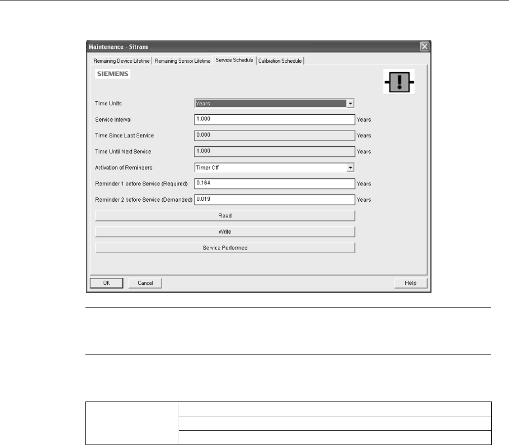
Parameter reference
SITRANS LR250 (mA/HART)
168 Operating Instructions, 08/2014, A5E32220602-AC
Service Interval (4.4.1.)
Note
The device always operates in years. Changing the units affects only the parameter view of
the Service Interval
parameters in SIMATIC PDM.
User-configurable recommended time between product inspections.
Values
Units
a)
: hours, days, years
Range: 0 to 20 years
Default: 1.0 year
a) Units are selectable only via SIMATIC PDM.
Time Since Last Service (4.4.2.)
Time elapsed since last service. Can be reset to zero after performing a service.
To reset to zero:
● In SIMATIC PDM, open the menu
Device – Maintenance
, click on the
Service Schedule
tab,
and click on
Service Performed
to restart the timer and clear any fault messages.
● Via the handheld programmer, manually reset
Time since Last Service (4.4.2.)
to zero.

Parameter reference
SITRANS LR250 (mA/HART)
Operating Instructions, 08/2014, A5E32220602-AC 169
Time Until Next Service (4.4.3.)
Read only.
Service Interval (4.4.1.)
less
Time Since Last Service (4.4.2.)
.
Activation of Reminders (4.4.4.)
Note
To mod
ify this parameter via SIMATIC PDM it must be accessed via the pull-down menu
Device – Maintenance
.
Allows you to enable a maintenance reminder.
Options
*
Timer OFF
ON - no reminders checked
ON - Reminder 1 (Maintenance Required) checked
ON - Reminders 1 and 2 checked
ON - Reminder 2 (Maintenance Demanded) checked
1. First set the values in
Reminder 1 before Service (Required) (4.4.5.)
/
Reminder 2 before
Service (Demanded) (4.4.6.)
.
2. Select the desired
Reminder Activation
option.
Reminder 1 before Service (Required) (4.4.5.)
If
Time Until Next Service (4.4.3.)
is equal to or less than this value, the device generates a
Maintenance Required
reminder.
Values
Range: 0 to Service Interval (4.4.1.)
Default: 0.164 years
1. Modify values as required.
2. Set
Activation of Reminders (4.4.4.)
to the desired option.

Parameter reference
SITRANS LR250 (mA/HART)
170 Operating Instructions, 08/2014, A5E32220602-AC
Reminder 2 before Service (Demanded) (4.4.6.)
If
Time Until Next Service (4.4.3.)
is equal to or less than this value, the device generates a
Maintenance Required
reminder.
Values
Range: 0 to Service Interval (4.4.1.)
Default: 0.019 years
1. Modify values as required
2. Set
Activation of Reminders (4.4.4.)
to the desired option.
Maintenance Status (4.4.7.)
Indicates which level of maintenance reminder is active.
Open the menu
View – Device Status
, click on the
Maintenance
tab and check the
Service
Schedule Status
window.
Acknowledge Status (4.4.8.)
Indicates which level of maintenance reminder has been acknowledged.
Open the menu
View – Device Status
, click on the
Maintenance
tab and check the
Service
Schedule Status
window.
Acknowledge (4.4.9.)
Acknowledges the current maintenance reminder.
To acknowledge a reminder via SIMATIC PDM:
1. Open the menu
View – Device Status
and click on the
Maintenance
tab.
2. In the
Service Schedule Status
section, click on
Acknowledge Warnings
.
To acknowledge a reminder via the handheld programmer:
1. Press
RIGHT arrow
twice to open parameter view and activate
Edit
Mode.
2. Press
RIGHT arrow
to acknowledge the reminder.

Parameter reference
SITRANS LR250 (mA/HART)
Operating Instructions, 08/2014, A5E32220602-AC 171
Calibration Schedule (4.5.)
Note
•
Default settings in the parameter tables are indicated with an asterisk (*) unless explicitly
stated.
•
Four sets of parameters allow you to monitor the Device/Sensor Lifetimes and set up
Maintenance/Service schedules, based on operating hours instead of a calendar-based
schedule. See also
Remaining Device Lifetime (4.2.)
,
Remaining Sensor Lifetime (4.3.)
,
and
Service Schedule (4.4.)
.
•
Performing a reset to
Factory Defaults
will reset all the Maintenance Schedule
parameters to their factory defaults.
•
The device operates in years. To view Calibration Interval parameters in hours or days
(via SIMATIC PDM only) see
Calibration Interval (4.5.1.)
.
The device tracks calibration intervals based on operating hours and monitors the predicted
lifetime to the next calibration. You can modify the Total Calibration Interval, set schedules for
maintenance reminders, and acknowledge them.
To access these parameters via SIMATIC PDM:
● Open the menu
Device – Maintenance
and select the
Calibration Schedule
tab.
● After modifying values/units as required, click on
Write
to accept the change, and
Read
to
view the effect of the change.
● Click on
Calibration Performed
to restart the timer and clear any fault messages.
Time Units
Options
a)
Hours; days; years
Default: years
a) Selectable only via SIMATIC PDM.

Parameter reference
SITRANS LR250 (mA/HART)
172 Operating Instructions, 08/2014, A5E32220602-AC
Calibration Interval (4.5.1.)
Note
The device always operates in years. Changing the units affects only the parameter view of
Remaining Sensor Life parameters in SIMATIC PDM.
User-configurable recommended time between product calibrations.
Values
Units
a)
: hours, days, years
Range: 0 to 20 years
Default: 1.0 year
a) Units are selectable only via SIMATIC PDM.
Time Since Last Calibration (4.5.2.)
Time elapsed since last calibration. Can be reset to zero after performing a calibration.
To reset to zero:
● In SIMATIC PDM, open the menu
Device – Maintenance
, click on the
Calibration Schedule
tab, and click on
Calibration Performed
to restart the timer and clear any fault messages.
● Via the handheld programmer, manually reset
Time Since Last Calibration (4.5.2.)
to zero.

Parameter reference
SITRANS LR250 (mA/HART)
Operating Instructions, 08/2014, A5E32220602-AC 173
Time Until Next Calibration (4.5.3.)
Read only.
Calibration Interval (4.5.1.)
less
Time Since Last Calibration (4.5.2.)
.
Activation of Reminders (4.5.4.)
Note
To modify this parameter via SIMATIC PDM it must be accesse
d via the pull-down menu
Device
– Maintenance.
Allows you to enable a maintenance reminder.
Options
Timer OFF
ON - no reminders checked
ON - Reminder 1 (Maintenance Required) checked
*
ON - Reminders 1 and 2 checked
ON—Reminder 2 (Maintenance Demanded) checked
1. First set the values in
Reminder 1 before Calibration (Required) (4.5.5.)
/
Reminder 2 before
Calibration (Demanded) (4.5.6.)
.
2. Select the desired
Activation of Reminders
option.
Reminder 1 before Calibration (Required) (4.5.5.)
If
Time Until Next Calibration (4.5.3.)
is equal to or less than this value, the device generates a
Maintenance Required
reminder.
Values
Range: 0 to Calibration Interval (4.5.1.)
Default: 0.164 years
1. Modify values as required.
2. Set
Activation of Reminders (4.5.4.)
to the desired option.
Parameter reference
SITRANS LR250 (mA/HART)
174 Operating Instructions, 08/2014, A5E32220602-AC
Reminder 2 before Calibration (Demanded) (4.5.6.)
If
Time Until Next Calibration (4.5.3.)
is equal to or less than this value, the device generates a
Maintenance Demanded
reminder.
Values
Range: 0 to Calibration Interval (4.5.1.)
Default: 0.164 years
1. Modify values as required.
2. Set Activation of Reminders (4.5.4.) to the desired option.
Maintenance Status (4.5.7.)
Indicates which level of maintenance reminder is active.
In SIMATIC PDM, open the menu
View – Device Status
, click on the
Maintenance
tab and check
the
Calibration Schedule Status
window.
Acknowledge Status (4.5.8.)
Indicates which level of maintenance reminder has been acknowledged.
In SIMATIC PDM, open the menu
View – Device Status
, click on the
Maintenance
tab and check
the
Calibration Schedule Status
window.
Acknowledge (4.5.9.)
Acknowledges the current maintenance reminder.
To acknowledge a reminder via SIMATIC PDM:
1. Open the menu
View – Device Status
and click on the
Maintenance
tab.
2. In the
Service Schedule Status
section, click on
Acknowledge Warnings
.
To acknowledge a reminder via the handheld programmer:
1. Press
RIGHT arrow
twice to open parameter view and activate
Edit
Mode.
2. Press
RIGHT arrow
to acknowledge the reminder.
Manufacture Date (4.6.)
Read only. The date of manufacture of the SITRANS LR250 (yy mm dd).
Powered Hours (4.7.)
Read only. Displays the number of hours the unit has been powered up since manufacture.
In SIMATIC PDM, open the menu
Device – Wear
.

Parameter reference
SITRANS LR250 (mA/HART)
Operating Instructions, 08/2014, A5E32220602-AC 175
Power-on Resets (4.8.)
Read only. The number of power cycles that have occurred since manufacture.
In SIMATIC PDM, open the menu
Device – Wear
.
LCD Fast Mode (4.9.)
Note
•
LCD Fast Mode takes effect only after 30 minutes of inactivity. (Each time the device is
powered up, a further 30 minutes of inactivity is required.)
•
LCD Fast Mode affects Measurement mode only; it has no effect on Navigation mode.
Enables a faster rate of measurement from the device by disabling most of the display area.
Only the bar graph will be refreshed when LCD Fast Mode is set to ON.
Values
ON or OFF
Default: OFF
LCD Contrast (4.10.)
The factory setting is for optimum visibility at room temperature and in average light conditions.
Extremes of temperature will lessen the contrast.
Values
Range: 0 (High contrast) to 20 (Low contrast). Default: 10
Adjust the value to improve visibility at room temperature and in average light conditions.
Change the value in small steps to ensure you can continue to read the display.
Secondary Value (4.11.)
Use the secondary value to capture the menu navigation path to any viewable parameter. Once
the navigation path is stored, the value of that parameter will be displayed in
Measurement
mode as the secondary value.
While in Parameter view of the current parameter, press the decimal point key. This stores the
path to the current parameter in the Secondary Value, and displays the value for that parameter
on the LCD display when in
Measurement
mode. See The LCD Display (Page 55) for an
illustration.
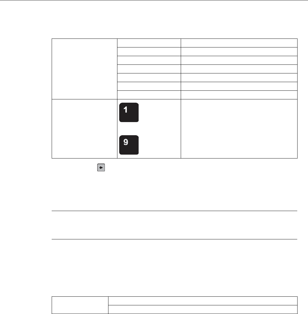
Parameter reference
SITRANS LR250 (mA/HART)
176 Operating Instructions, 08/2014, A5E32220602-AC
Memory Test (4.12.)
Allows verification of the RAM, EEPROM, and Flash memory of the SITRANS LR250.
LCD Display
IDLE
No test in progress.
BUSY
Test in progress.
PASS
Memory test successful.
FAIL
Test failed.
Err1
Test returned unexpected results.
P Oxcafe
Test passed with result data.
F Oxcafe
Test failed with result data.
Handheld programmer
entry
to
Any numeric key from 1 to 9 activates test.
● Press
RIGHT arrow
to edit then press any numeric key from 1 to 9 to activate the test.
● The reading will display BUS and then the test result text.
Communication (5.)
Note
Default settings in the parameter tables are indicated with an asterisk (*) unless explicitly
stated.
Device Address (5.1.)
Sets the device address or poll ID on a HART network. Any address other than 0 will cause the
output current to be a fixed value, and the current will not indicate the reading.
Values
Range: 0 to 15
Default: 0
To set Device Address via SIMATIC PDM:
● Open the project in
Process Device Network View
then right-click on the device.
● Go to
Object Properties > Connection
to access the field
Short Address.

Parameter reference
SITRANS LR250 (mA/HART)
Operating Instructions, 08/2014, A5E32220602-AC 177
Security (6.)
Note
Default settings in the parameter tables are indicated with an asterisk (*) unless explicit
ly
stated.
Remote Access (6.1.)
Access Control (6.1.1.)
Note
If access control is changed to limit remote access, it can only be reset via the handheld
programmer.
Enables/disables the read/write access to parameters via remote communications.
Options
Read only No changes are permitted via remote
communications.
*
Read Write
Changes are permitted.
Restricted Sets the status to Read only, with the
potential for another HART device to change
this parameter only, via remote
communications.

Parameter reference
SITRANS LR250 (mA/HART)
178 Operating Instructions, 08/2014, A5E32220602-AC
Local Access (6.2.)
Write Protect (6.2.1.)
Note
This loc
k affects only the handheld programmer. A remote master can change configuration
if Access Control (6.1.1.)
is set to allow this.
Prevents any changes to parameters via the handheld programmer.
Options
Range: 0 to 9999
*
Unlock value [stored in PIN to Unlock (6.2.2.)]
Lock Off
Any other value
Lock On
● To turn Lock On, key in any value other than the Unlock Value stored in
PIN to Unlock
(6.2.2.)
.
● To turn Lock Off, key in the Unlock Value stored in
PIN to Unlock (6.2.2.)
.
PIN to Unlock (6.2.2.)
Note
•
Do not lose your Unlock Value: it cannot be displayed once
Write Protect (6.2.1.)
has
been set to a different value.
•
Valid only for operation via the handheld programmer.
•
A reset to
Factory Defaults
will not restore the unlock value at time of shipping.
Stores the value to be entered in
Write Protect (6.2.1.)
to unlock programming. If
Write Protect
(6.2.1.)
is set to a different value,
PIN to Unlock (6.2.2.)
does not display the Unlock value.
Handheld
Programmer Values
Range: 0 to 9999
Value when shipped: 1954. Not restored by a reset to Factory Defaults.
– – – –
Display when Lock is on
Language (7.)
Selects the language to be used on the LCD.
Options
*
English
Deutsch
Français
Español

Parameter reference
SITRANS LR250 (mA/HART)
Operating Instructions, 08/2014, A5E32220602-AC 179
8.1
Alphabetical parameter list
Note
For a detailed list of parameters see
Parameter Reference (Page 127). Maintenance
Parameters are no
t listed below. See
Remaining Device Lifetime (4.2.)
,
Remaining Sensor
Lifetime (4.3.)
,
Service Schedule (4.4.)
and
Calibration Schedule (4.5.)
for those parameters.
20 mA Setpoint (2.6.3.)
4 mA Setpoint (2.6.2.)
Access Control (6.1.1.)
Algorithm (2.8.4.1.)
Analog Output Scaling (2.6.)
Auto False Echo Suppression (2.8.7.1.)
Auto False Echo Suppression Range (2.8.7.2.)
Breakpoint 1-9 (2.8.8.1.)
Breakpoint 10-18 (2.8.8.2.)
Breakpoint 19-27 (2.8.8.3.)
Breakpoint 28-36 (2.8.8.4.)
Breakpoint 37-40 (2.8.8.5.)
Calibration (2.3.)
CLEF Range (2.8.4.4.)
Communication (5.)
Confidence (2.8.6.1.)
Current Internal Temperature (3.2.1.)
Current Output Function (2.6.1.)
Damping Filter (2.2.4.)
Device (2.1.)
Device Address (5.1.)
Diagnostics (3.)
Distance Measurement (2.8.9.3.)
Echo Lock (2.8.5.1.)
Echo Profile (3.1.)
Echo Quality (2.8.6.)

Parameter reference
SITRANS LR250 (mA/HART)
180 Operating Instructions, 08/2014, A5E32220602-AC
Echo Select (2.8.4.)
Echo Strength (2.8.6.2.)
Echo Threshold (2.8.4.3.)
Electronics Temperature (3.2.)
Empty Rate per Minute (2.4.3.)
Fail-safe (2.5.)
Fail-Safe mA Value (2.5.3.)
Far Range (2.8.2.)
Fill Rate per Minute (2.4.2.)
Firmware Revision (2.1.2.)
Hardware Revision (2.1.1.)
High Calibration Pt. (2.3.2.)
Highest value (3.2.2.)
Hover Level (2.8.7.3.)
Language (7.)
LCD Contrast (4.10.)
LCD Fast Mode (4.9.)
Level 1 (2.7.2.1.)
Level Measurement (2.8.9.1.)
Linearization (2.7.)
Loader Revision (2.1.3.)
Local Access (6.2.)
LOE Timer (2.5.2.)
Low Calibration Pt. (2.3.1.)
Lowest value (3.2.3.)
mA Output Value (2.6.6.)
Manufacture Date (4.6.)
Master Reset (4.1.)
Material (2.2.3.)
Material Level (2.5.1.)
Maximum mA limit (2.6.5.)
Maximum Volume (2.7.1.2.)
Measured Values (2.8.9.)

Parameter reference
SITRANS LR250 (mA/HART)
Operating Instructions, 08/2014, A5E32220602-AC 181
Memory Test (4.12.)
Menu Timeout (2.1.5.)
Minimum mA limit (2.6.4.)
Near Range (2.8.1.)
Noise Average (2.8.6.3.)
Order Option (2.1.4.)
PIN to Unlock (6.2.2.)
Position Detect (2.8.4.2.)
Power-on Resets (4.8.)
Powered Hours (4.7.)
Propagation Factor (2.8.3.)
Quick Start (1.)
Quick Start Wizard (1.1.)
Rate (2.4.)
Remote Access (6.1.)
Response Rate (2.4.1.)
Sampling (2.8.5.)
Sampling Down (2.8.5.3.)
Sampling Up (2.8.5.2.)
Shaper Mode (2.8.7.4.)
Signal Processing (2.8.)
Secondary Value (4.11.)
Security (6.)
Sensor (2.2.)
Sensor Mode (2.2.2.)
Sensor Offset (2.3.3.)
Service (4.)
Setup (2.)
Space Measurement (2.8.9.2.)
Table 1-8 (2.7.2.)
Table 9-16 (2.7.3.)
Table 17-24 (2.7.4.)

Parameter reference
SITRANS LR250 (mA/HART)
182 Operating Instructions, 08/2014, A5E32220602-AC
Table 25-32 (2.7.5.)
TVT Setup (2.8.7.)
TVT Shaper (2.8.8.)
Units (2.2.1.)
Vessel Dimension A (2.7.1.3.)
Vessel Dimension L (2.7.1.4.)
Vessel Shape (2.7.1.1.)
Volume (2.7.1.)
Volume 1 (2.7.2.2.)
Volume Measurement (2.8.9.4.)
Write Protect (6.2.1.)