Siemens Canada Siemens Milltronics Process Instruments LR250 SITRANS LR 250 TANK LEVEL PROBING RADAR User Manual SITRANS LR250 FOUNDATION FIELDBUS
Siemens Canada Ltd. - Siemens Milltronics Process Instruments SITRANS LR 250 TANK LEVEL PROBING RADAR SITRANS LR250 FOUNDATION FIELDBUS
Contents
User Manual 4

SITRANS LR250 (FOUNDATION FIELDBUS)
Operating Instructions, 08/2014, A5E32221411-AC 143
Parameter reference
8
Note
• See
Enter PROGRAM
mode under LCD Display (Page 57) for detailed instructions.
• To view a particular parameter in AMS, see Operating via AMS Device Manager
(Page 79).
• Do not use the handheld programmer at the same time as AMS Device Manager, or
erratic operation may result.
• For Quick Access to parameters via the handheld programmer, press
Home
, then
enter the menu number, for example:
2.2.1.
to access parameter
Hardware Revision
(2.2.1.)
.
• In Navigation mode
, ARROW keys ( )
navigate the menu in the direction of
the arrow.
• Press
RIGHT arrow
to open
Edit
Mode, or to save a modification.
Parameters are identified by name and organized into function groups. Menus arranged on up to
four levels give access to associated features and options. See LCD menu structure (Page 296)
for a chart.
Parameters noted as
Read Only
in this section of the manual can not be written via the LUI,
however they may be accessible via other tools. For those accessible via AMS Device Manager,
directions are shown in section
Operating via AMS Device Manager
on the pages referenced.
Quick Start Wizard
The Quick Start Wizard groups together all the settings you need to configure a device for a
simple application. You can access it either via AMS Device Manager or via the handheld
programmer.
● Do not use the Quick Start Wizard via the handheld programmer to modify individual
parameters. (Perform customization only after the Quick Start has been completed.)
● Each time the Quick Start Wizard is initiated via the handheld programmer, the startup
settings are factory defaults. The Wizard will not recall previous user-defined settings. (Note:
Values set using the Quick Start Wizard via AMS Device Manager are saved and recalled
each time it is initiated.)
● When using AMS Device Manager, the Resource and LTB Blocks must be set to Out of
Service mode before any configuration changes (changes to parameters affecting block
output) can be written. The blocks do not need to be set to Out of Service when the Quick
Start Wizard is initiated via the handheld programmer.

Parameter reference
7.1 Operating via AMS Device Manager
SITRANS LR250 (FOUNDATION FIELDBUS)
144 Operating Instructions, 08/2014, A5E32221411-AC
Quick Start (1.)
Note
For detailed instructions see Quick Start Wizard via the handheld programmer (Page 65) or
Quick Start Wizard via AMS Device Manager (Page 85).
Setup (2.)
Note
• See Parameter menus (Page 60) or Operating via AMS Device Manager (Page 79) for
instructions.
• Default settings in the parameter tables are indicated with an asterisk (*) unless explicitly
stated.
• Values shown in the following tables can be entered via the handheld programmer.
Identification (2.1.)
Tag (2.1.1.)
Read only. Text that can be used in any way. A recommended use is as a unique label for a field
device in a plant. Limited to 32 ASCII characters.
Note
The tag can only be changed from a remote master such as NIFBUS-Configurator or DeltaV.
Descriptor (2.1.2.)
Read only. Text that can be used in any way. Limited to 32 ASCII characters. No specific
recommended use.
To access this parameter via AMS Device Manager see
Identification
under Identification
(RESOURCE) (Page 111).
Message (2.1.3.)
Read only. Text that can be used in any way. Limited to 32 ASCII characters. No specific
recommended use.
To access this parameter via AMS Device Manager see Identification under Identification
(RESOURCE). (Page 111)

Parameter reference
7.1 Operating via AMS Device Manager
SITRANS LR250 (FOUNDATION FIELDBUS)
Operating Instructions, 08/2014, A5E32221411-AC 145
Device (2.2.)
Hardware Revision (2.2.1.)
Read only. Corresponds to the electronics hardware of the Field Device.
Firmware Revision (2.2.2.)
Read only. Corresponds to the software or firmware that is embedded in the Field Device.
Loader Revision (2.2.3.)
Read only. Corresponds to the software used to update the Field Device.
Sensor (2.3.)
Unit (2.3.1)
Sensor measurement unit.
Values
m, cm, mm, ft, in
* m
Level Unit (2.3.2.)
Select engineering units for Level.
Options
m, cm, mm, ft, in, %
* %

Parameter reference
7.1 Operating via AMS Device Manager
SITRANS LR250 (FOUNDATION FIELDBUS)
146 Operating Instructions, 08/2014, A5E32221411-AC
PV Units (volume/level) (2.3.3.)
Note
• Default unit of AIFB 1 or 2 is percent.
• You can select a different unit for your application.
• PV (Primary Value): the output from the Level Transducer Block. See
Level Transducer
Block (LTB)
and
How the LTB works
: in manual
Foundation Fieldbus for Level
Instruments
(7ML19985MP01) for more details.
Select units for either volume or level.
Level values
m, cm, mm, ft, in, %
Volume values
liter, gal, ImpGal, %
Percent value
* %
Temperature Units (2.3.4.)
Selects the engineering unit to be displayed with the value representing temperature.
Options
DEGC, DEGF, DEGR, K
* DEGC
Material (2.3.5.)
Automatically configures the device to operate in the chosen application type, by changing one
or more of the following parameters:
Propagation Factor (2.5.3.)
,
Position Detect (2.5.7.2.)
,
and/or
CLEF Range (2.5.7.4.)
.
Options
* LIQUID
LIQUID LOW DK a) (low dielectric liquid - CLEF algorithm enabled)
Related parameters
Propagation Factor (2.5.3.)
Position Detect (2.5.7.2.)
CLEF Range (2.5.7.4.)
a) dK < 3.0
You can configure each of the related parameters, to suit your particular application.
Parameter reference
7.1 Operating via AMS Device Manager
SITRANS LR250 (FOUNDATION FIELDBUS)
Operating Instructions, 08/2014, A5E32221411-AC 147
LOE Timer (2.3.6.)
Note
See Loss of Echo (LOE) (Page 274) for more detail.
Sets the time to elapse since the last valid reading, before the Fail-safe material level is
reported.
Values
Range:
0
to
7200
seconds
Default: 100 s
Calibration (2.3.7)
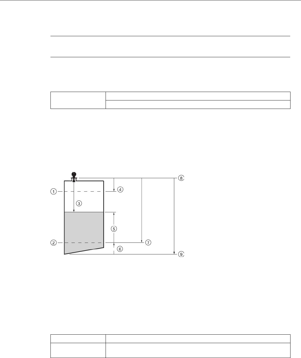
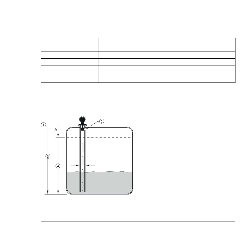
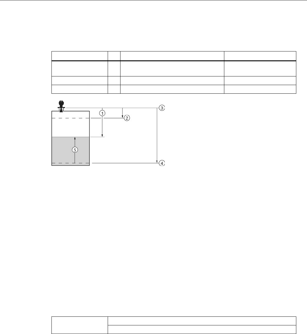
Low Calibration Pt. (2.3.7.1.)
Distance from sensor reference point to Low Calibration Point (corresponding to Low Level
Point). Units are defined in
Unit (2.3.1.).
①
High level point (default 100%)
⑥
Level offset (if used)
②
Low level point (0%)
⑦
Low calibration point
③
Sensor value
⑧
Sensor reference point
a)
④
High calibration point
⑨
Far range
⑤
Level
a) The point from which level measurement is referenced [see Flat Faced Flange (Page 258) and
Threaded Horn Antenna with extension (Page 221) and Flanged encapsulated antenna
(3"/DN80/80A sizes and larger). (Page 232) ].
Values
Range:
0.00
to
20.00
m. Default 20.00 m
Related parameters
Unit (2.3.1.)
Far Range (2.5.2.)

Parameter reference
7.1 Operating via AMS Device Manager
SITRANS LR250 (FOUNDATION FIELDBUS)
148 Operating Instructions, 08/2014, A5E32221411-AC
High Calibration Point (2.3.7.2.)
Distance from sensor reference point 1) to High Calibration Point (corresponding to High Level
Point). Units are defined in
Unit (2.3.1.).
See
Low Calibration Point (2.3.7.1.)
for an illustration.
Values
Range:
0.00
to
20.00
m. Default 0.00 m
Related parameters
Unit (2.3.1.), Near Range (2.5.1.)
When setting the High Calibration Point value, note that echoes are ignored within
Near Range
(2.5.1.).
1) The value produced by the echo processing which represents the distance from sensor
reference point to the target. [see Threaded Horn Antenna with extension, (Page 224) Flanged
Horn with extension (Page 228), and Flanged encapsulated antenna (3"/DN80/80A sizes and
larger) (Page 232)].
Sensor Offset (2.3.7.3.)
A constant offset that can be added to or subtracted from the sensor value to compensate for a
shifted sensor reference point. (For example, when adding a thicker gasket or reducing the
standoff/nozzle height.) The units are defined in
Unit (2.3.1.)
.
Values
Range:
-99.999
to
99.999
Default: 0.000 m
Related Parameters
Unit (2.3.1.)
See
How the LTB works
: in manual
Foundation Fieldbus for Level Instruments
(7ML19985MP01)
for more details on sensor offset.
Low Level Point (2.3.7.4.)
The level when the material is at Low Calibration Point. The unit is defined in
Level Unit (2.3.2.).
Values
Range:
-999999
to
999999
Default: 0%
High Level Point (2.3.7.5.)
The level when the material is at High Calibration Point. The unit is defined in
Level Unit (2.3.2.).
Values
Range: -
999999
to +
999999
Default: 100%

Parameter reference
7.1 Operating via AMS Device Manager
SITRANS LR250 (FOUNDATION FIELDBUS)
Operating Instructions, 08/2014, A5E32221411-AC 149
Level Offset (2.3.7.6.)
A constant offset that can be added to Level. The unit is defined in
Level Unit (2.3.2.)
.
Values
Range:
-999999
to +
999999
Default: 0%
Rate (2.3.8.)
Response Rate (2.3.8.1.)
Sets the reaction speed of the device to measurement changes.
Note
Changing Response Rate resets
Fill Rate per Minute (2.3.8.2)
,
Empty rate per Minute
(2.3.8.3)
, and
Shots (2.5.6.)
.
Response Rate (2.3.8.1.)
Fill Rate per Minute (2.3.8.2.)/
Empty rate per Minute (2.3.8.3.)
Shots (2.5.6.)
* Slow 0.1 m/min (0.32 ft/min) 25
Medium 1.0 m/min (3.28 ft/min) 10
Fast 10.0 m/min (32.8 ft/min) 5
Use a setting just faster than the maximum filling or emptying rate (whichever is faster).
Fill Rate per Minute (2.3.8.2.)
Defines the maximum rate at which the reported sensor value is allowed to decrease. Allows you
to adjust the SITRANS LR250 response to decreases in the actual material level. Fill Rate is
automatically updated whenever
Response Rate (2.3.8.1.)
is altered.
Sensor value is the value produced by the echo processing which represents the distance from
sensor reference point to the target [see
Low Calibration Point (2.3.7.1.)
for an illustration].
Options
Range:
0 to 999999
m / min.
Response Rate (2.3.8.1.)
Fill Rate per Minute (2.3.8.2.)
* Slow 0.1 m/min (0.32 ft/min)
Medium 1.0 m/min (3.28 ft/min)
Fast 10.0 m/min (32.8 ft/min)
Altered by:
Response Rate (2.3.8.1.)
Related parameters
Level Unit (2.3.2.)
Enter a value slightly greater than the maximum vessel-filling rate, in units per minute.

Parameter reference
7.1 Operating via AMS Device Manager
SITRANS LR250 (FOUNDATION FIELDBUS)
150 Operating Instructions, 08/2014, A5E32221411-AC
Empty Rate per Minute (2.3.8.3)
Defines the maximum rate at which the reported sensor value is allowed to increase. Adjusts the
SITRANS LR250 response to increases in the actual material level. Empty Rate is automatically
updated whenever Response Rate is altered
.
The sensor value is the value produced by the echo processing which represents the distance
from sensor reference point to the target [see
Low Calibration Point (2.3.7.1.)
for an illustration].
Options
Range:
0 to 99999
m / min.
Response Rate (2.3.8.1.)
Empty Rate
* Slow 0.1 m/min (0.32 ft/min)
Medium 1.0 m/min (3.28 ft/min)
Fast 10.0 m/min (32.8 ft/min)
Altered by:
Response Rate (2.3.8.1)
Related parameters
Level Unit (2.3.2.)
Enter a value slightly greater than the vessel’s maximum emptying rate, in units per minute.
Linearization (2.4.)
Volume (2.4.1.)
Carries out a volume conversion from a level value.
Parameter reference
7.1 Operating via AMS Device Manager
SITRANS LR250 (FOUNDATION FIELDBUS)
Operating Instructions, 08/2014, A5E32221411-AC 151
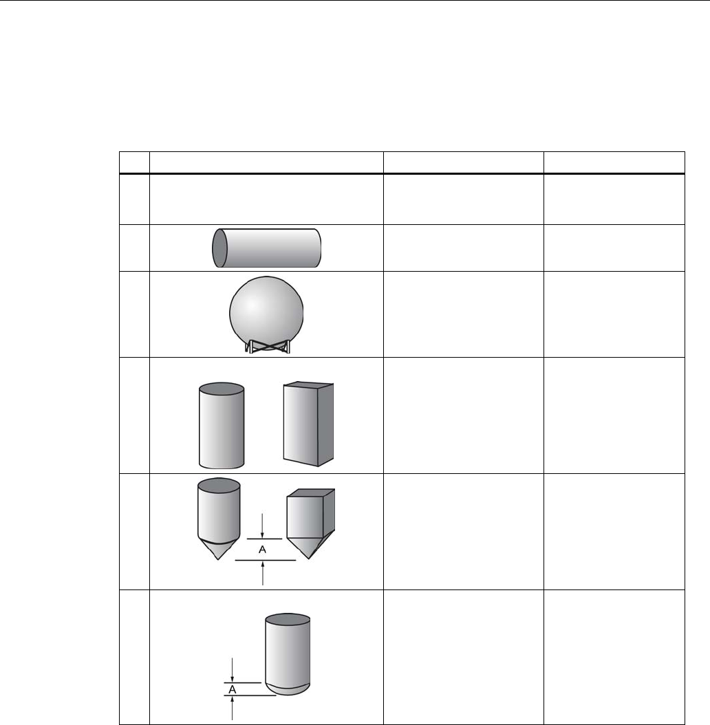
Vessel Shape (2.4.1.1.)
Defines the vessel shape and allows the LR250 to calculate volume instead of level. If
None
is
selected, no volume conversion is performed. Select the vessel shape matching the monitored
vessel or reservoir.
Vessel Shape
LCD DISPLAY/ Description
Also required
* None NONE/
No volume calculation
required
N/A
CYLINDER/
Flat end horizontal cylinder
Maximum volume
SPHERE/
Sphere
Maximum volume
LINEAR/
Upright, linear (flat bottom)
Maximum volume
CONICAL BOT/
Conical or pyramidal
bottom
Maximum volume,
dimension A
PARABOLIC
BOT/Parabolic bottom
Maximum volume,
dimension A
Parameter reference
7.1 Operating via AMS Device Manager
SITRANS LR250 (FOUNDATION FIELDBUS)
152 Operating Instructions, 08/2014, A5E32221411-AC
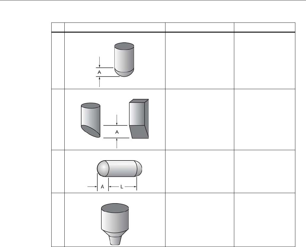
Vessel Shape
LCD DISPLAY/ Description
Also required
HALF SPHERE BOT/
Half-sphere bottom
Maximum volume,
dimension A
FLAT SLOPED BOT/
Flat sloped bottom
Maximum volume,
dimension A
PARABOLIC ENDS/
Parabolic end horizontal
cylinder
Maximum volume,
dimension A, dimension
L
LINEAR TABLE a) /
Linearization table
(level/volume breakpoints)
Maximum volume, level
breakpoints, volume
breakpoints
a) Linearization Table must be selected in order for level/volume values [see
XY
index (2.4.1.5.)
] to be transferred.

Parameter reference
7.1 Operating via AMS Device Manager
SITRANS LR250 (FOUNDATION FIELDBUS)
Operating Instructions, 08/2014, A5E32221411-AC 153
Maximum Volume (2.4.1.2.)
The maximum volume of the vessel. Units are defined in
PV Units (volume/ level) (2.3.3.)
. Enter
the vessel volume corresponding to High Calibration Point. The volume calculation is based on
the maximum volume and scaled according to the vessel shape selected. If no vessel shape is
entered, the default is 100, and the reading will be a percentage value.
Values
Range:
0.0000
to
999999
Default: 100.0
Related Parameters
Low Calibration Pt. (2.3.7.1.)
High Calibration Pt. (2.3.7.2.)
Vessel Shape (2.4.1.1.)
For readings in volumetric units instead of percentage values:
1. Select a volumetric unit from
PV Units (volume/level) (2.3.3.)
.
2. Enter the vessel volume corresponding to High Calibration Point.
Vessel Dimension A (2.4.1.3.)
The height of the vessel bottom in Level Units when the bottom is conical, pyramidal, parabolic,
spherical, or flat -sloped. If the vessel is horizontal with parabolic ends, the depth of the end. See
Vessel Shape (2.4.1.1.)
for an illustration.
Values
Range:
0.0000
to
999999
in Level Units
Default: 0.0
Related Parameters
Vessel Shape (2.4.1.1.)
Dimension L (2.4.1.4.)
Length of the cylindrical section of a horizontal parabolic end vessel, in Level Units. See
Vessel
Shape (2.4.1.1.)
for an illustration.
Values
Range:
0.0000
to
999999
in Level Units
Default: 0.0
Related Parameters
Vessel Shape (2.4.1.1.)
Parameter reference
7.1 Operating via AMS Device Manager
SITRANS LR250 (FOUNDATION FIELDBUS)
154 Operating Instructions, 08/2014, A5E32221411-AC
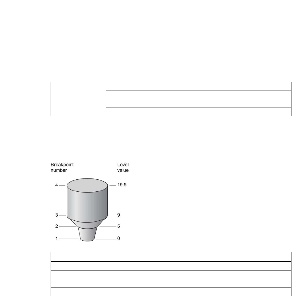
XY index (2.4.1.5.)
Level/Volume breakpoints allow you to define a complex vessel shape as a series of segments.
A value is assigned to each level breakpoint and a corresponding value is assigned to each
volume breakpoint.
Volume values are defined in volume units and can be percent or volumetric; level values are
defined in level units, and can be percent or linear.
Level values
Range:
0.0000
to
999999
(m, cm, mm, ft, in, %)
Default: 0.0
Volume values
Range:
0.0000
to
999999
(% or volumetric units)
Default: 0.0
Enter up to 32 level breakpoints, where the corresponding volume is known. The values
corresponding to 100% and 0% levels must be entered. The breakpoints can be ordered from
top to bottom, or the reverse.
Example (values are for example purposes only)
Breakpoint Number
Level value (m)
Volume value (l)
1 0 0
2 5 500
3 9 3000
4 19.5 8000

Parameter reference
7.1 Operating via AMS Device Manager
SITRANS LR250 (FOUNDATION FIELDBUS)
Operating Instructions, 08/2014, A5E32221411-AC 155
Entering breakpoints via the hand-held programmer:
1. The default for level values is percent: if you want to select units instead, navigate to
Setup
(2.) > Sensor (2.3.) > Level Unit (2.3.2.)
, and select the desired unit.
2. Navigate to
Setup (2.) > Sensor (2.3.) > PV Units (volume/level) (2.3.3.)
, and select the
desired volume units.
3. Go to
XY index (2.4.1.5.)
and enter the number of the breakpoint you wish to adjust: for
example, for breakpoint
1
enter
1
.
4. Go to
X value (2.4.1.6.)
and enter the level value for the breakpoint just identified.
5. Go to
Y value (2.4.1.7.)
and enter the volume value for the breakpoint just identified.
6. Repeat steps 3 to 5 until values have been entered for all required breakpoints.
X value (2.4.1.6.)
See
XY Index (2.4.1.5.)
.
Y value (2.4.1.7.)
See
XY Index (2.4.1.5.)
.
Entering breakpoints via AMS:
See Linearization (LTB) (Page 97)
After completing the above steps you will need to configure AIFB 1 and/or AIFB 2. [See
AIFB 1
(2.6.)
and
AIFB 2 (2.7.)
for details.]
Signal Processing (2.5.)
In AMS Device Manager, see the General tab under Signal Processing (LTB) (Page 99).
Near Range (2.5.1.)
The range in front of the device (measured from the sensor reference point within which any
echoes will be ignored. (This is sometimes referred to as "Blanking" or "Dead Zone".) The
factory setting is 50 mm (2") past the end of the antenna, and the range is dependent on the
antenna type and process connection. [See Threaded Horn Antenna with extension (Page 221)
and Flanged Horn (Page 226) for antenna heights to sensor reference point.]
Values
Range:
0
to
20
m (0 to 65.6 ft)
Default depends on antenna type and process connection.
Examples: 1.5" threaded horn 185.3 mm (7.3")
4" horn with stainless steel flange
and 100 mm (4") extension
373.3 mm (14.7")
Related parameters
Unit (2.2.1.)

Parameter reference
7.1 Operating via AMS Device Manager
SITRANS LR250 (FOUNDATION FIELDBUS)
156 Operating Instructions, 08/2014, A5E32221411-AC
Far Range (2.5.2.)
Note
Far Range can extend beyond the bottom of the vessel.
Allows the material level to drop below Low Calibration Point without generating a Loss of Echo
(LOE) state. See
Low Calibration Pt. (2.3.7.1.)
for an illustration.
Values
Range: Min. =
Low Calibration Pt.
Max. =
33
m (108.27 ft)
Default: Value for Low Calibration Pt. + 1 m (3.28 ft)
Related parameters
Unit (2.3.1.)
CLEF (Constrained Leading Edge Fit) Range (2.5.7.4.) a)
a) The value set for Far Range becomes the CLEF Range maximum. If the value for Far Range is
changed after a CLEF Range value is entered, CLEF Range is reset to its default (0.00 m).
Use this feature if the measured surface can drop below the Low calibration point in normal
operation.
Propogation Factor (2.5.3.)
Note
• When operating in a stillpipe, values for
CLEF Range (2.5.7.4.)
, and for the Propagation
Factor, should be set according to the pipe size. See the table below.
• For reliable results the antenna size must be close to the pipe size.
Parameter reference
7.1 Operating via AMS Device Manager
SITRANS LR250 (FOUNDATION FIELDBUS)
Operating Instructions, 08/2014, A5E32221411-AC 157
Compensates for the change in microwave velocity due to propagation within a metal stillpipe
instead of in free space.
Values
Range:
0.3
to
1.0
depending on pipe size.
Default:
1.0000
Nominal Pipe Size
a) 40 mm (1.5") 50 mm (2") 80 mm (3") 100 mm (4")
Propagation Factor
0.9844 0.988 0.9935 0.9965
CLEF Range (2.5.7.4.)
Low calibration
point - 700 mm
(2.29 ft)b)
Low calibration
point - 700 mm
(2.29 ft)b)
Low calibration
point - 1000
mm (3.28 ft)b)
Low calibration
point - 1000 mm
(3.28 ft)b)
a) Since pipe dimensions may vary slightly, the propagation factor may also vary.
b) CLEF range covers the whole measurement range except first 700 or 1000 mm from unit
reference
point (see A in graphic below)
①
sensor reference point
③
low calibration point
②
air gap
④
CLEF range 2.5.7.4.
A
700 or 1000 mm
Note
Flanged encapsulated antenna
For Flanged encapsulated antenna (7ML5432) match the process connection size to the
pipe diameter whenever possible (for example, mount a DN80/3" flange on DN80/3" pipe).

Parameter reference
7.1 Operating via AMS Device Manager
SITRANS LR250 (FOUNDATION FIELDBUS)
158 Operating Instructions, 08/2014, A5E32221411-AC
Minimum Sensor Value (2.5.4.)
The minimum usable value for the measuring range, in units defined in
Unit (2.3.1.)
.
(Default =
0.0 m)
To view this parameter via AMS Device Manager see
Range
under Signal Processing (LTB)
(Page 99).
Maximum Sensor Value (2.5.5.)
The maximum usable value for the measuring range, in units defined in
Unit (2.3.1.)
. (Default =
33.0 m)
To view this parameter via AMS Device Manager see
Range
under Signal Processing (LTB)
(Page 99).
Shots (2.5.6.)
The number of echo profile samples averaged to produce a measurement.
Values
Range:
1
to
25
Default: 25 a)
a) To meet accuracy specification, the number of shots must be set to 25 [see Performance
(Page 213)].
Echo Select (2.5.7.)
Algorithm (2.5.7.1.)
Selects the algorithm to be applied to the echo profile to extract the true echo.
Options
*
tF
T
rue
F
irst echo
F
F
irst echo
L
L
argest echo
BLF
B
est of
L
argest and
F
irst echo

Parameter reference
7.1 Operating via AMS Device Manager
SITRANS LR250 (FOUNDATION FIELDBUS)
Operating Instructions, 08/2014, A5E32221411-AC 159
Position Detect (2.5.7.2.)
Defines where on the echo the distance measurement is determined.
Options
Center
* Hybrid (Center and CLEF)
CLEF (Constrained Leading Edge Fit)
Related parameters
CLEF Range (2.5.7.4.)
If the vessel bottom is being reported as the level instead of the actual material level (at low level
conditions), or if the dielectric constant of the liquid to be monitored is less than 3, we
recommend setting Position Detect to
Hybrid
and
CLEF (Constrained Leading Edge Fit) Range
(2.5.7.4.)
to 0.5 m (1.64 ft).
Echo Threshold (2.5.7.3.)
Sets the minimum echo confidence that the echo must meet in order to prevent a Loss of Echo
condition and the expiration of the Fail-safe (LOE) timer. When
Confidence (2.5.9.1.)
exceeds
Echo Threshold (2.5.7.3.)
, the echo is accepted as a valid echo and is evaluated.
Values
Range:
0
to
99
Default: 5
Related Parameters
Loss of Echo (LOE) Timer (2.3.6.)
Confidence (2.5.9.1.)
Use this feature when an incorrect material level is reported.
CLEF Range (2.5.7.4.)
Note
CLEF Range is referenced from Low Calibration Point (process empty level).
The CLEF algorithm is used mainly to allow correct level reporting for low dK materials which
may otherwise cause an incorrect reading in an empty or almost empty vessel.
It is used from Low Calibration Point (process empty level ) up to the level defined by CLEF
Range (see illustration below). Above that point the Center algorithm is used. For more detail
see CLEF Range (Page 269).
Parameter reference
7.1 Operating via AMS Device Manager
SITRANS LR250 (FOUNDATION FIELDBUS)
160 Operating Instructions, 08/2014, A5E32221411-AC
Values
Range:
0
to
20
m (0 to 65.6 ft)
Default: 0.0 m
Related parameters
Position Detect (2.5.7.2.)
①
CLEF Range
②
Sensor reference point
③
Low calibration point (process empty level)
In applications with low dK materials we recommend setting CLEF Range to 0.5 m (1.64 ft) and
Position Detect (2.5.7.2.)
to Hybrid.
Sampling (2.5.8.)
Provides a method of checking the reliability of a new echo before accepting it as the valid
reading, based on numbers of samples above or below the currently selected echo.
Echo Lock (2.5.8.1.)
Note
Ensure the agitator is always running while SITRANS LR250 is monitoring the vessel, to
avoid stationary blade detection.
Selects the measurement verification process. See
Echo Lock (2.5.8.1.)
for more details.
Options
Lock Off (no verification)
Maximum Verification
* Material Agitator
Total Lock
Related parameters
Fill Rate per Minute (2.3.8.2.)
Empty Rate per Minute (2.3.8.3.)
Up Sampling (2.5.8.2.)
Down Sampling (2.5.8.3.)
For radar applications, Material Agitator is the most often-used setting, to avoid agitator blade
detection.

Parameter reference
7.1 Operating via AMS Device Manager
SITRANS LR250 (FOUNDATION FIELDBUS)
Operating Instructions, 08/2014, A5E32221411-AC 161
Sampling Up (2.5.8.2.)
Specifies the number of consecutive echoes that must appear above the echo currently
selected, before the measurement is accepted as valid.
Values
Range:
1
to
50
Default: 5
Down Sampling (2.5.8.3.)
Specifies the number of consecutive echoes that must appear below the echo currently selected,
before the measurement is accepted as valid.
Values
Range:
1
to
50
Default: 2 (see Related parameters)
Related
parameters
Echo Lock (2.5.8.1.) If Echo Lock set to any value other than its default (2),
then Down Sampling default = 5.
Echo Quality (2.5.9.)
Confidence (2.5.9.1.)
Indicates echo reliability: higher values represent better echo quality. The display shows the
echo confidence of the last measurement.
Echo Threshold (2.5.7.3.)
defines the minimum
criterion for echo confidence.
Values
(view only)
0
to
99
Echo Threshold (2.5.7.3.)
Related Parameters
Open the menu
Device – Echo Profile Utilities
and click on the tab
Echo Profile
.
Echo Strength (2.5.9.2.)
Displays the absolute strength (in dB above 1 μV rms) of the echo selected as the measurement
echo.
Values
(view only)
Range:
–20
to
99

Parameter reference
7.1 Operating via AMS Device Manager
SITRANS LR250 (FOUNDATION FIELDBUS)
162 Operating Instructions, 08/2014, A5E32221411-AC
TVT (Auto False Echo Suppression) Setup (2.5.10.)
Note
• Make sure material level is below all known obstructions when Auto False Echo
Suppression is used to learn the echo profile. (An empty
or almost empty vessel is recommended.)
• Note the distance to material level when Auto False Echo learns the environment. Set
Auto False Echo Suppression Range to a shorter
distance to avoid the material echo being screened out.
• Set Auto False Echo Suppression and Auto False Echo Suppression Range during
startup, if possible.
• If the vessel contains an agitator it should be running.
• Before adjusting these parameters, rotate the instrument for best signal (lower false-echo
amplitude).
Auto False Echo Suppression (2.5.10.1.)
Used together with
Auto False Echo Suppression Range (2.5.10.2.)
to screen out false echoes
in a vessel with known obstructions. A ’learned TVT’ (time varying threshold) replaces the
default TVT over a specified range. See
Auto False Echo Suppression (Page 271) for a more
detailed explanation.
Parameter reference
7.1 Operating via AMS Device Manager
SITRANS LR250 (FOUNDATION FIELDBUS)
Operating Instructions, 08/2014, A5E32221411-AC 163
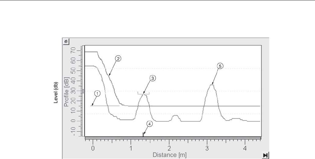
Before Auto False Echo Suppression
①
TVT Hover Level
④
echo marker
②
default TVT
⑤
material level
③
false echo
1. Determine Auto False Echo Suppression Range. Measure the actual distance from the
sensor reference point to the material surface using a rope or tape measure.
2. Subtract 0.5 m (20") from this distance, and use the resulting value.
Parameter reference
7.1 Operating via AMS Device Manager
SITRANS LR250 (FOUNDATION FIELDBUS)
164 Operating Instructions, 08/2014, A5E32221411-AC
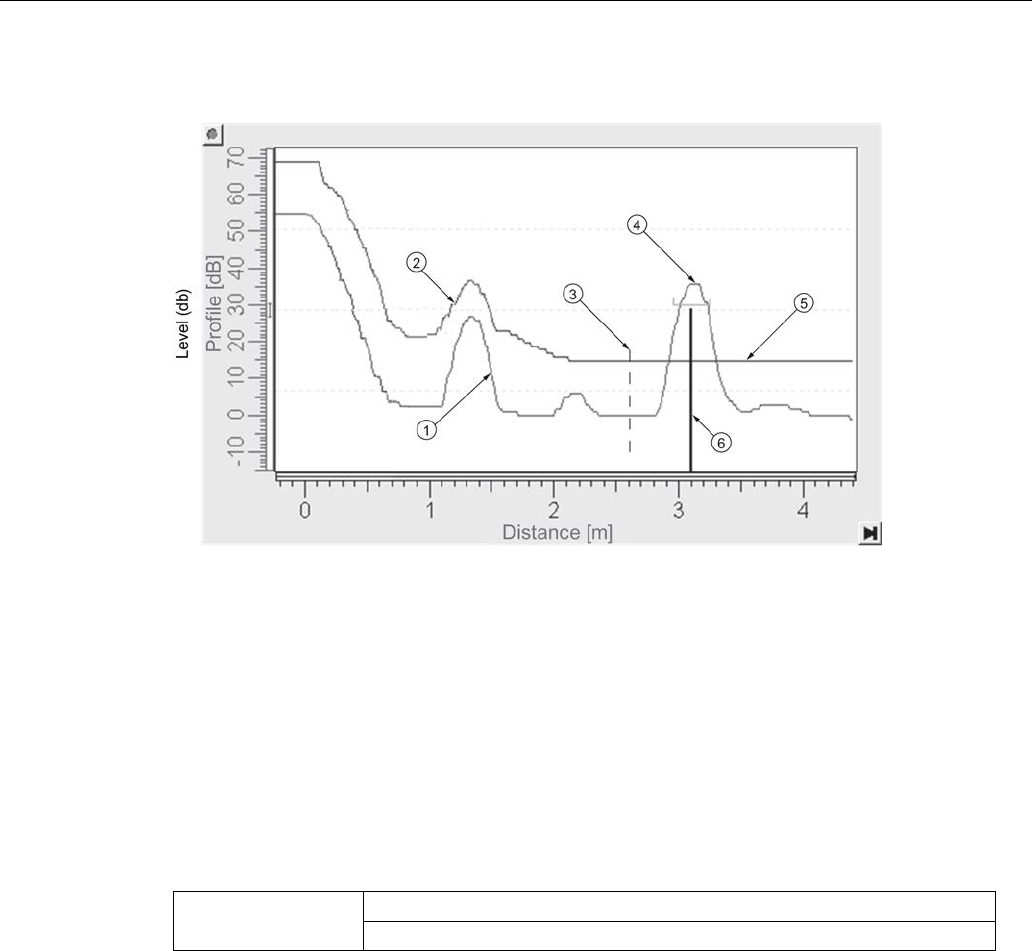
After Auto False Echo Suppression
① false echo ④ material level
② learned TVT ⑤ default TVT
③ Auto False Echo Suppression Range ⑥ echo marker
To use Auto False Echo Suppression via AMS Device Manager
note value calculated in step 1
and see Auto False Echo Suppression (Page 100).
Auto False Echo Suppression Range (2.5.10.2.)
Defines the endpoint of the Learned TVT distance. Units are defined in
Unit (2.3.1.)
.
Values
Range:
0.00
to
30.00
m
Default: 1.00 m
1. Press
RIGHT arrow
to open Edit mode.
2. Enter the new value and press
RIGHT arrow
to accept it.
3. Set
Auto False Echo Suppression (2.5.10.1.)
.

Parameter reference
7.1 Operating via AMS Device Manager
SITRANS LR250 (FOUNDATION FIELDBUS)
Operating Instructions, 08/2014, A5E32221411-AC 165
Hover Level (2.5.10.3.)
Defines how high the TVT (Time Varying Threshold) is placed above the noise floor of the echo
profile, as a percentage of the difference between the peak of the largest echo in the profile and
the noise floor. See
Auto False Echo Suppression (2.5.10.1)
for an illustration.
Values
Range:
0
to
100
%
Default: 40%
When the device is located in the center of the vessel, the TVT hover level may be lowered to
increase the confidence level of the largest echo.
Shaper Mode (2.5.10.4.)
Enables/disables
TVT shaper
(2.5.11.)
Options
ON
* OFF
TVT Shaper (2.5.11.)
Note
• The range is –100 to +100 bits. With 2 bits per dB this gives a range of –50 to +50 dB.
•
Shaper Mode (2.5.10.4.)
must be turned
ON
in order for TVT shaper points to be
transferred.
Adjusts the TVT (Time Varying Threshold) at a specified range (breakpoint on the TVT). This
allows you to reshape the TVT to avoid unwanted echoes. There are 40 breakpoints arranged in
5 groups. (We recommend using SIMATIC PDM to access this feature.)
To use TVT shaper via LUI (local user interface):
1. Go to
Shaper Mode (2.5.10.4.)
and select
On
.
2. In TVT shaper, go to Breakpoint
1-9 (2.5.11.1.)
.
3. Open Breakpoint 1 and enter the TVT Offset value (between –50 and 50).
4. Go to the next Breakpoint and repeat step 3 until all desired breakpoint values have been
entered.

Parameter reference
7.1 Operating via AMS Device Manager
SITRANS LR250 (FOUNDATION FIELDBUS)
166 Operating Instructions, 08/2014, A5E32221411-AC
Breakpoint 1-9 (2.5.11.1.)
Values
Range:
–100
to
+100
bits (equivalent to – 50 to +50 dB)
Default: 0 dB
Breakpoint 10-18 (2.5.11.2.)
Values
Range:
–100
to
+100
bits (equivalent to – 50 to +50 dB)
Default: 0 dB
Breakpoint 19-27 (2.5.11.3.)
Values
Range:
–100
to
+100
bits (equivalent to – 50 to +50 dB)
Default: 0 dB
Breakpoint 28-36 (2.5.11.4.)
Values
Range:
–100
to
+100
bits (equivalent to – 50 to +50 dB)
Default: 0 dB
Breakpoint 37-40 (2.5.11.5.)
Values
Range:
–100
to
+100
bits (equivalent to – 50 to +50 dB)
Default: 0 dB
To access TVT Shaper via AMS Device Manager see TVT Shaper (Page 100).

Parameter reference
7.1 Operating via AMS Device Manager
SITRANS LR250 (FOUNDATION FIELDBUS)
Operating Instructions, 08/2014, A5E32221411-AC 167
AIFB1 (2.6.)
Note
• Default settings in the parameter tables are indicated with an asterisk (*) unless explicitly
stated.
• All AIFB parameters are read only via LUI and AMS Device Manager, and can only be
changed using a remote host such as DeltaV or NI-FBUS Configurator.
• AIFB 1 and AIFB 2 are not active out of the box. These blocks will show Out of Service
on the LCD at startup. If these blocks are needed for an FF application, use a tool such
as DeltaV or NI-FBUS Configurator to configure and schedule the blocks. See
Configuration
in manual
Foundation Fieldbus for Level Instruments
(7ML19985MP01) for
further details.
Static Revision Number (2.6.1.)
The revision level of the static data associated with Analog Input Function Block 1. The Static
Revision No. is updated whenever a configuration parameter is changed.
Mode (2.6.2.)
Used to request an operating mode from the Analog Input Function Block.
Options
Auto Mode (AUTO)
Manual Mode (MAN)
Out of Service (OOS)
Allows you to put the SITRANS LR250 into Out of Service Mode and then reset it to Auto Mode.
Manual Mode can be used when simulating output. See
Simulation
in manual
Foundation
Fieldbus for Level Instruments
(7ML19985MP01) for more details.
Parameter reference
7.1 Operating via AMS Device Manager
SITRANS LR250 (FOUNDATION FIELDBUS)
168 Operating Instructions, 08/2014, A5E32221411-AC
Channel (2.6.3.)
Used to select between the different Level Transducer Block outputs.
Options
Description
Reference point
LEVEL/VOLUME Level value converted to Volume [through
Linearization (2.4.)
]
Low Calibration Point
LEVEL * Level value Low Calibration Point
DISTANCE Distance value Sensor Reference Point
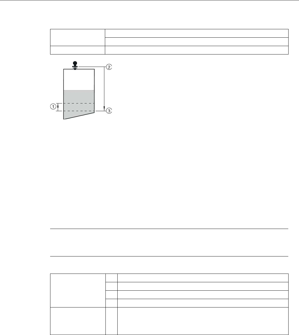
①
Distance
②
High Calibration Point (process full level)
③
Sensor reference point a)
④
Low Calibration Point (process empty level)
⑤
Level
a) The point from which High and Low Calibration points are referenced: see Dimension drawings
(Page 221) and Threaded Horn Antenna with extension (Page 221).
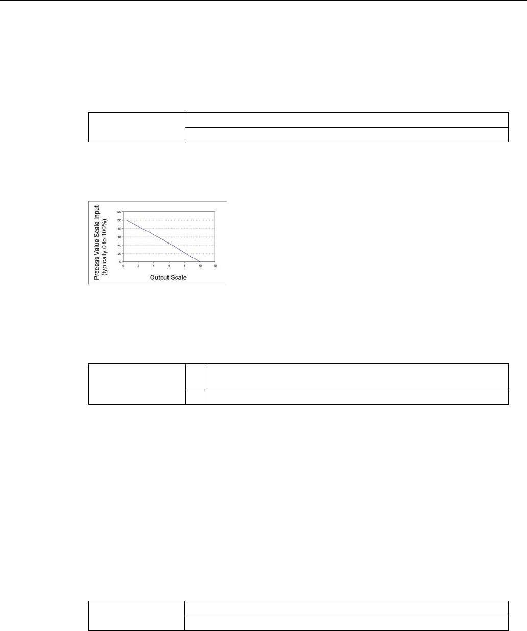
Input Scaling (2.6.4.)
Lower Value (2.6.4.1.)
Defines the operational lower range value of the input value (Process Value Scale) in PV
(volume/level) Units. Process Value Scale normalizes the input value to a customer-defined
range.
Values
Range:
-999999
to
999999
Default: 0 %
Parameter reference
7.1 Operating via AMS Device Manager
SITRANS LR250 (FOUNDATION FIELDBUS)
Operating Instructions, 08/2014, A5E32221411-AC 169
Upper Value (2.6.4.2.)
Defines the operational upper range value of the input value (Process Value Scale) in PV
(volume/level) Units. Process Value Scale normalizes the input value to a customer-defined
range.
Values
Range:
-999999
to
999999
Default: 100 %
Provides Output values
(Out) to AIFB 1 or AIFB 2
Unit (2.6.4.3.)
Engineering unit to be displayed with the output value.
Values
m, cm, mm, ft, in, cu m, L, HL, cu in, cu ft, cu yd, gal, imp gal,
bushels, Bbl, Bbl liquid, percent, PA, Follow out unit
* %
Decimal Point (2.6.4.4.)
Read only. The number of digits to display after the decimal point (set to 0 decimal places).
Output Scaling (2.6.5.)
Scales the Process Variable. The function block parameter OUT SCALE contains the values of
the lower limit and upper limit effective range in AIFB 1 units.
Lower Value (2.6.5.1.)
Defines the operational lower range value of the output value in AIFB 1 units.
Values
Range:
-999999
to
999999
Default: 0%

Parameter reference
7.1 Operating via AMS Device Manager
SITRANS LR250 (FOUNDATION FIELDBUS)
170 Operating Instructions, 08/2014, A5E32221411-AC
Upper Value (2.6.5.2.)
Defines the operational upper range value of the output value in AIFB1 units.
Values
Range:
-999999
to
999999
Default: 100%
Unit (2.6.5.3.)
Engineering unit to be displayed with the output value.
Values
m, cm, mm, ft, in, cu m, L, HL, cu in, cu ft, cu yd, gal, imp gal,
bushels, Bbl, Bbl liquid, percent, PA, Follow out unit
* %
Decimal Point (2.6.5.4.)
Read only. The number of digits to display after the decimal point (set to two decimal places).
Alarms and Warnings (2.6.6.)
High Limit Alarm (2.6.6.1.)
The setting for the upper alarm limit in AIFB1 units.
Values
Range:
-Infinity
to
Infinity
Default: Inf
High Limit Warning (2.6.6.2.)
The setting for the upper warning limit in AIFB1 units.
Values
Range:
-Infinity
to
Infinity
Default: Inf

Parameter reference
7.1 Operating via AMS Device Manager
SITRANS LR250 (FOUNDATION FIELDBUS)
Operating Instructions, 08/2014, A5E32221411-AC 171
Low Limit Warning (2.6.6.3.)
The setting for the lower warning limit in AIFB1 units.
Values
Range:
-Infinity
to
Infinity
Default: -Inf
Low Limit Alarm (2.6.6.4.)
The setting for the lower alarm limit in AIFB1 units.
Values
Range:
-Infinity
to
Infinity
Default: -Inf
Limit Hysteresis (2.6.6.5.)
Hysteresis is used to adjust the sensitivity of the trigger for alarm messages. It is used to
compensate when a process variable fluctuates around the same value as a limit. A high level
alarm occurs when a value exceeds an upper limit. The alarm’s status remains true until the
value drops below the limit minus the alarm hysteresis. The directions are reversed for low limit
detection.
Values
Range:
0
to
50
Default: 0.50
Enter a value for the hysteresis here, to be used for all warnings and alarms. The units are the
same as the Output scale, i.e. AIFB1 units.
Display (2.6.7.)
Filter Time Constant (2.6.7.1.)
The time constant for the damping filter. The damping filter smooths out the response to a
sudden change in level. This is an exponential filter and the engineering unit is always in
seconds. See Damping (Page 273) for more detail.
Values
Range:
0
to
600
s
Default: 0 a)
a) To meet accuracy specification, Filter Time Constant (PV_FTIME) must be changed from
default of 0.0 s to a minimum of 10.0 seconds [see Performance (Page 213)].

Parameter reference
7.1 Operating via AMS Device Manager
SITRANS LR250 (FOUNDATION FIELDBUS)
172 Operating Instructions, 08/2014, A5E32221411-AC
AIFB 2 (2.7.)
See
AIFB1 (2.6.):
the parameters for
AIFB 2
are identical to
AIFB 1
.
Measured Values (2.8.)
(for diagnostic purposes)
Read only. Allows you to view measured values for diagnostic purposes.
Main Output (PV - Primary Value) (2.8.1.)
The value for level, or volume (if volume conversion is selected).
In AMS Device Manager, see Process Variables Level Transducer Block-LTB (Page 128).
Output, no linearization (SV1 - Secondary Value 1) (2.8.2.)
The value for level.
Output, no level offset (SV2 - Secondary Value 2) (2.8.3.)
The value for distance.
Diagnostics (3.)
Echo Profile (3.1.)
Allows you to request the current echo profile via the handheld programmer, or via AMS Device
Manager. For more detail see Echo Processing (Page 266).
To request a profile via AMS Device Manager:
See Echo Profile (Page 103).
To request a profile via the handheld programmer:
1. Navigate to
Level Meter > Diagnostics (3.) > Echo Profile (3.1.)
.
2. Press RIGHT arrow to request a profile. [See Requesting an Echo Profile (Page 70) for more
details.]

Parameter reference
7.1 Operating via AMS Device Manager
SITRANS LR250 (FOUNDATION FIELDBUS)
Operating Instructions, 08/2014, A5E32221411-AC 173
Fault Reset (3.2.)
Clears faults (see chart below).
Clearing a fault in one parameter of a ’maintenance pair’, automatically clears a fault in the
second parameter of the pair. For example, entering S3 or S4 will clear a fault on Device
Lifetime Reminder 1 (Maintenance Required), and on Device Lifetime Reminder 2 (Maintenance
Demanded). This applies when clearing faults via the handheld programmer, or the 375 Field
Communicator.
Fault code
Description
S3
Device Lifetime Reminder 1 (Maintenance Required)
S4
Device Lifetime Reminder 2 (Maintenance Demanded)
S6
Sensor Lifetime Reminder 1 (Maintenance Required)
S7
Sensor Lifetime Reminder 2 (Maintenance Demanded)
S8
Device Service Reminder 1 (Maintenance Required)
S9
Device Service Reminder 2 (Maintenance Demanded)
S12
Internal Temperature High
S17
Calibration Schedule Reminder 1 (Maintenance Required)
S18
Calibration Schedule Reminder 2 (Maintenance Demanded)
To clear a fault using the handheld programmer:
● Enter the fault code number then press
RIGHT arrow
.
Electronics Temperature (3.3.)
To access the following parameters via AMS Device Manager see
Electronics Temperature
under Maintenance & Diagnostics (LTB) (Page 104).
Minimum Value (3.3.1.)
The minimum recorded internal electronics temperature, reported in units defined in
Temperature Units (2.3.4.)
.
Maximum Value (3.3.2.)
The maximum recorded internal electronics temperature, reported in units defined in
Temperature Units (2.3.4.).

Parameter reference
7.1 Operating via AMS Device Manager
SITRANS LR250 (FOUNDATION FIELDBUS)
174 Operating Instructions, 08/2014, A5E32221411-AC
Peak Values (3.4.)
Minimum Measured Value (3.4.1.)
The minimum recorded Sensor value, reported in units defined in
Unit (2.3.1.)
.
Maximum Measured Value (3.4.2.)
The maximum recorded Sensor value, reported in units defined in
Unit (2.3.1.)
.
Service (4.)
Note
Default settings in the parameter tables are indicated with an asterisk (*) unless explicitly
stated.

Parameter reference
7.1 Operating via AMS Device Manager
SITRANS LR250 (FOUNDATION FIELDBUS)
Operating Instructions, 08/2014, A5E32221411-AC 175
Master Reset (4.1.)
Note
• The following parameters are not reset by any reset type: Write Protection, PIN to Unlock,
Auto False Echo Suppression Range, Learned TVT.
• While an FF Object Dictionary Reset is in progress, do not perform an action using the
local display interface until the reset is complete. This could cause a temporary loss of
communications.
Reset Type
Result
Factory Defaults a) Default. Resets all user parameters to the manufacturer’s default settings.
Following this type of reset, complete reprogramming is required.
Standard Defaults Resets all parameters to standard default settings.
Informational Resets parameters such as Block Descriptor, Strategy, Device Install
Date, Device Message.
Functional a) Resets parameters that control device behavior and functionality (such as
Low Calibration Point).
Warm Start Has the same effect as recycling power to the device.
FF Object Dictionary Resets the FF standard block profile parameters (such as block tags) to
their specified defaults. This option also clears any function block
parameters and device schedule b) set by the user.
a) The only difference between Factory Defaults and Functional reset is that Factory Defaults resets
maintenance parameters, such as device and sensor wear, calibration and maintenance timers.
Functional reset does not reset these parameters.
b) See
Data transmission
in manual
Foundation Fieldbus for Level Instruments
(7ML19985MP01) for
further details.
To access via AMS Device Manager see Master Reset under Operation (RESOURCE)
(Page 113).
To perform a reset via the handheld programmer:
1. Press
RIGHT arrow
to open Edit Mode then scroll down to the desired reset type and
press RIGHT arrow to select it.
2. Press
LEFT arrow
to exit.
After performing a master reset, the device will stop measuring, the Resource and Level
Transducer Blocks will go to
Out of Service
, and the LUI will show the
Quick Start Wizard
until
the device is configured.

Parameter reference
7.1 Operating via AMS Device Manager
SITRANS LR250 (FOUNDATION FIELDBUS)
176 Operating Instructions, 08/2014, A5E32221411-AC
Remaining Device Lifetime (4.2.)
Note
• Default settings in the parameter tables are indicated with an asterisk (*) unless explicitly
stated.
• Four sets of parameters allow you to monitor the Device/Sensor Lifetimes and set up
Maintenance/Service schedules, based on operating hours instead of a calendar-based
schedule. See also
Remaining Sensor Lifetime (4.3.)
,
Service Schedule (4.4.)
, and
Calibration Schedule (4.5.)
.
• Performing a reset to
Factory Defaults
will reset all the Maintenance Schedule
parameters to their factory defaults.
• The device operates in years. To view Remaining Device Lifetime parameters in hours
(via AMS Device Manager only) see
Remaining Device Lifetime
under Maintenance &
Diagnostics (RESOURCE) (Page 116)
.
The device tracks itself based on operating hours and monitors its predicted lifetime. You can
modify the expected device lifetime, set up schedules for maintenance alerts, and acknowledge
them.
The maintenance warnings and alarms are communicated to the end user through status
information. This information can be integrated into any Asset Management system.
To access these parameters via AMS Device Manager see
Remaining Device Lifetime
under
Maintenance & Diagnostics (RESOURCE) (Page 116).
Time in operation (4.2.2.)
Read only. The amount of time the device has been operating.
Remaining lifetime (4.2.3.)
Read only.
LIfetime (Expected) (4.2.1.)
less
Time in Operation (4.2.2.).

Parameter reference
7.1 Operating via AMS Device Manager
SITRANS LR250 (FOUNDATION FIELDBUS)
Operating Instructions, 08/2014, A5E32221411-AC 177
Activation of Reminders (4.2.4.)
Allows you to enable a maintenance reminder.
Options
REMinder 1 (Maintenance REQuired)
REMinder 2 (Maintenance DEManded)
REMinders 1 AND 2 (Maintenance Required and Maintenance
Demanded)
* OFF
1. First set the reminder values in
Reminder 1 before Lifetime (Required) (4.2.5.)/Reminder 2
before Lifetime (Demanded) (4.2.6.)
.
2. Select the desired
Activation of Reminders
option.
Reminder 1 before Lifetime (Required) (4.2.5.)
If
Remaining Lifetime (4.2.3.)
is equal to or less than this value, the device generates a
Maintenance Required reminder.
Values
Range: 0 to 20 years
Default: 0.164 years
1. Modify limit values as required.
2. Set
Activation of Reminders (4.2.4.)
to the desired option.
Reminder 2 before Lifetime (Demanded) (4.2.6.)
If
Remaining Lifetime (4.2.3.)
is equal to or less than this value, the device generates a
Maintenance Demanded reminder.
Values
Range: 0 to 20 years
Default: 0.019 years
1. Modify values as required.
2. Set
Activation of Reminders (4.2.4.)
to the desired option.
Maintenance Status (4.2.7.)
Indicates which level of maintenance reminder is active.
To display the level of maintenance reminder that is active in AMS Device Manager see
Extended Diagnostics
under Device Diagnostics [Resource Block - RESOURCE (Page 124)].

Parameter reference
7.1 Operating via AMS Device Manager
SITRANS LR250 (FOUNDATION FIELDBUS)
178 Operating Instructions, 08/2014, A5E32221411-AC
Acknowledge Status (4.2.8.)
Indicates which level of maintenance reminder has been acknowledged.
Acknowledge (4.2.9.)
Acknowledges the current maintenance reminder.
To acknowledge a reminder via the handheld programmer:
1. Press
RIGHT arrow
twice to open parameter view and activate
Edit
Mode.
2. Press
RIGHT arrow
to acknowledge the reminder.
Remaining Sensor Lifetime (4.3.)
Note
• Default settings in the parameter tables are indicated with an asterisk (*) unless explicitly
stated.
• Four sets of parameters allow you to monitor the Device/Sensor Lifetimes and set up
Maintenance/Service schedules, based on operating hours instead of a calendar-based
schedule. See also
Remaining Device Lifetime (4.2.), Service Schedule (4.4.)
,
and
Calibration Schedule (4.5.)
.
• Performing a reset to Factory Defaults will reset all the Maintenance Schedule
parameters to their factory defaults.
• The device operates in years. To view Remaining Sensor Lifetime parameters in hours
(via AMS Device Manager only) see
Remaining Sensor Lifetime
in Maintenance &
Diagnostics (LTB) (Page 104).
The device monitors the predicted lifetime of the sensor (the components exposed to the vessel
environment). You can modify the expected sensor lifetime, set up schedules for maintenance
reminders, and acknowledge them.
To access these parameters via AMS Device Manager see
Remaining Sensor Lifetime
in
Maintenance & Diagnostics (LTB) (Page 104).
Lifetime (expected) (4.3.1.)
Allows you to override the factory default.
Values
Units: years
Range:
0
to
20
years
Default: 10.00 years

Parameter reference
7.1 Operating via AMS Device Manager
SITRANS LR250 (FOUNDATION FIELDBUS)
Operating Instructions, 08/2014, A5E32221411-AC 179
Time in Operation (4.3.2.)
The amount of time the sensor has been operating. Can be reset to zero after performing a
service or replacing the sensor.
To reset to zero:
● Via the handheld programmer, manually reset
Time in Operation (4.3.2.)
to zero.
Remaining Lifetime (4.3.3.)
Read only.
Lifetime (expected) (4.3.1.)
less
Time in Operation (4.3.2.)
.
Activation of Reminders (4.3.4.)
Allows you to enable a maintenance reminder.
Options
REMinder 1 (Maintenance Required)
REMinder 2 (Maintenance Demanded)
REMinders 1 and 2 (Maintenance Required and Maintenance
Demanded)
* OFF
1. First set the values in
Reminder 1 before Lifetime (Required) (4.3.5.)
/
Reminder 2 before
Lifetime(Demanded) (4.3.6.)
.
2. Select the desired
Activation of Reminders
option.
Reminder 1 before Lifetime (Required) (4.3.5.)
If
Remaining Lifetime (4.3.3.)
is equal to or less than this value, the device generates a
Maintenance Required
reminder.
Values
Range:
0
to
20 years
Default: 0.164 years
1. Modify limit values as required.
2. Set
Activation of Reminders (4.3.4.)
to the desired option.
Parameter reference
7.1 Operating via AMS Device Manager
SITRANS LR250 (FOUNDATION FIELDBUS)
180 Operating Instructions, 08/2014, A5E32221411-AC
Reminder 2 before Lifetime (Demanded) (4.3.6.)
If
Remaining Lifetime (4.3.3.)
is equal to or less than this value, the device generates a
Maintenance Demanded
reminder.
Values
Range:
0
to
20
years
Default: 0.019 years
1. Modify limit values as required.
2. Set
Activation of Reminders (4.3.4.)
to the desired option.
Maintenance Status (4.3.7.)
Indicates which level of maintenance reminder is active.
To display the level of maintenance reminder in AMS Device Manager see
Extended
Diagnostics
under Device Diagnostics (Level Transducer Block - LTB) (Page 119).
Acknowledge Status (4.3.8.)
Indicates which level of maintenance reminder has been acknowledged.
Acknowledge (4.3.9.)
Acknowledges the current maintenance reminder.
To acknowledge a reminder via the handheld programmer:
1. Press
RIGHT arrow
twice to open parameter view and activate
Edit
Mode.
2. Press
RIGHT arrow
to acknowledge the reminder.

Parameter reference
7.1 Operating via AMS Device Manager
SITRANS LR250 (FOUNDATION FIELDBUS)
Operating Instructions, 08/2014, A5E32221411-AC 181
Service Schedule (4.4.)
Note
• Default settings in the parameter tables are indicated with an asterisk (*) unless explicitly
stated.
• Four sets of parameters allow you to monitor the Device/Sensor Lifetimes and set up
Maintenance/Service schedules, based on operating hours instead of a calendar-based
schedule. See also
Remaining Device Lifetime (4.2.)
,
Remaining Sensor Lifetime (4.3.)
,
and
Calibration Schedule (4.5.)
.
• Performing a reset to
Factory Defaults
will reset all the Maintenance Schedule
parameters to their factory defaults.
• The device operates in years. To view Service Interval parameters in hours or days (via
AMS Device Manager only) see
Service Schedule (4.4.1.)
.
The device tracks service intervals based on operating hours and monitors the predicted lifetime
to the next service. You can modify the Total Service Interval, set schedules for maintenance
reminders, and acknowledge them.
The maintenance warnings and alarms are communicated to the end user through status
information. This information can be integrated into any Asset Management system.
To access these parameters via AMS Device Manager see
Service Schedule
under
Maintenance & Diagnostics (LTB) (Page 104).
Service Interval (4.4.1.)
User-configurable recommended time between product inspections.
Values
Units: years
Range:
0
to
20
years
Default: 1.0 year
Time Since Last Service (4.4.2.)
Time elapsed since last service. Can be reset to zero after performing a service.
To reset to zero:
● Via the handheld programmer, manually reset
Time Since Last Service (4.4.2.)
to zero.
Time Until Next Service (4.4.3.)
Read only.
Service Interval (4.4.1.)
less
Time Since Last Service (4.4.2.)
.

Parameter reference
7.1 Operating via AMS Device Manager
SITRANS LR250 (FOUNDATION FIELDBUS)
182 Operating Instructions, 08/2014, A5E32221411-AC
Activation of Reminders (4.4.4.)
Allows you to enable a maintenance reminder.
Options
* Timer OFF
ON NO LIMITS
ON - REMinder 1 (Maintenance Required) checked
ON - REMinders 1 and 2 checked
ON - REMinder 2 (Maintenance Demanded) checked
1. First set the values in
Reminder 1 before Service (Required) (4.4.5.)
/
Reminder 2 before
Service (Demanded) (4.4.6.)
.
2. Select the desired
Activation of Reminders
option.
Reminder 1 before Service (Required) (4.4.5.)
If
Time Until Next Service (4.4.3.)
is equal to or less than this value, the device generates a
Maintenance Required
reminder.
Values
Range:
0
to
20
years
Default: 0.164 years
1. Modify limit values as required.
2. Set
Activation of Reminders (4.4.4.)
to the desired option.
Reminder 2 before Service (Demanded) (4.4.6.)
If
Time Until Next Service (4.4.3.)
is equal to or less than this value, the device generates a
Maintenance Demanded
reminder.
Values
Range:
0
to
20
years
Default: 0.019 years
1. Modify values as required
2. Set
Activation of Reminders (4.4.4.)
to the desired option.
Maintenance Status (4.4.7.)
Indicates which level of maintenance reminder is active.
To display the level of maintenance reminder in AMS Device Manager see
Extended
Diagnostics
under Device Diagnostics (Level Transducer Block - LTB) (Page 119).

Parameter reference
7.1 Operating via AMS Device Manager
SITRANS LR250 (FOUNDATION FIELDBUS)
Operating Instructions, 08/2014, A5E32221411-AC 183
Acknowledge Status (4.4.8.)
Indicates which level of maintenance reminder has been acknowledged.
Acknowledge (4.4.9.)
Acknowledges the current maintenance reminder.
To acknowledge a reminder via the handheld programmer:
1. Press
RIGHT arrow
twice to open parameter view and activate
Edit
Mode.
2. Press
RIGHT arrow
to acknowledge the reminder.
Calibration Schedule (4.5.)
Note
• Default settings in the parameter tables are indicated with an asterisk (*) unless explicitly
stated.
• Four sets of parameters allow you to monitor the Device/Sensor Lifetimes and set up
Maintenance/Service schedules, based on operating hours instead of a calendar-based
schedule. See also
Remaining Device Lifetime (4.2.)
,
Remaining Sensor Lifetime (4.3.)
,
and
Service Schedule (4.4.)
.
• Performing a reset to
Factory Defaults
will reset all the Maintenance Schedule
parameters to their factory defaults.
• The device operates in years. To view Calibration Interval parameters in hours (via AMS
Device Manager only) see
Calibration Schedule
under Maintenance & Diagnostics
(RESOURCE) (Page 116).
The device tracks calibration intervals based on operating hours and monitors the predicted
lifetime to the next calibration. You can modify the Total Calibration Interval, set schedules for
maintenance reminders, and acknowledge them.
To access these parameters via AMS Device Manager see
Calibration Schedule
under
Maintenance & Diagnostics (RESOURCE) (Page 116).
Calibration Interval (4.5.1.)
User-configurable recommended time between product calibrations.
Values
Units: years
Range:
0
to
20
years
Default: 1.0 year

Parameter reference
7.1 Operating via AMS Device Manager
SITRANS LR250 (FOUNDATION FIELDBUS)
184 Operating Instructions, 08/2014, A5E32221411-AC
Time Since Last Calibration (4.5.2.)
Time elapsed since last calibration. Can be reset to zero after performing a calibration.
To reset to zero:
● Via the handheld programmer, manually reset
Time Since Last Calibration (4.5.2.)
to zero.
Time Until Next Calibration (4.5.3.)
Read only.
Calibration Interval (4.5.1.)
less
Time Since Last Calibration (4.5.2.)
.
Activation of Reminders (4.5.4.)
Allows you to enable a maintenance reminder.
Options
* Timer OFF
ON NO LIMITS
ON - REMinder 1 (Maintenance Required) checked
ON - REMinders 1 and 2 checked
ON—REMinder 2 (Maintenance Demanded) checked
1. First set the limit values in
Reminder 1 before Calibration (Required) (4.5.5.)
/
Reminder 2
before Calibration (Demanded) (4.5.6.)
.
2. Select the desired
Activation of Reminders
option.
Reminder 1 before Calibration (Required) (4.5.5.)
If
Time Until Next Calibration (4.5.3.)
is equal to or less than this value, the device generates a
Maintenance Required
reminder.
Values
Range:
0
to
20
years
Default: 0.164 years
1. Modify limit values as required.
2. Set
Activation of Reminders (4.5.4.)
to the desired option.
Parameter reference
7.1 Operating via AMS Device Manager
SITRANS LR250 (FOUNDATION FIELDBUS)
Operating Instructions, 08/2014, A5E32221411-AC 185
Reminder 2 before Calibration (Demanded) (4.5.6.)
If
Time Until Next Calibration (4.5.3.)
is equal to or less than this value, the device generates a
Maintenance Demanded
reminder.
Values
Range:
0
to
20
years
Default: 0.019 years
1. Modify limit values as required.
2. Set
Activation of Reminders (4.5.4.)
to the desired option.
Maintenance Status (4.5.7.)
Indicates which level of maintenance reminder is active.
To display the level of maintenance reminder that is active in AMS Device Manager see
Extended Diagnostics
under Device Diagnostics (Resource Block - RESOURCE) (Page 124).
Acknowledge Status (4.5.8.)
Indicates which level of maintenance reminder has been acknowledged.
Acknowledge (4.5.9.)
Acknowledges the current maintenance reminder.
To acknowledge a reminder via the handheld programmer:
1. Press
RIGHT arrow
twice to open parameter view and activate
Edit
Mode.
2. Press
RIGHT arrow
to acknowledge the reminder.
Manufacture Date (4.6.)
Read only. The date of manufacture of the SITRANS LR250 (mm/dd/yyyyhh.mm).
Powered Hours (4.7.)
Read only. Displays the number of hours the unit has been powered up since manufacture.
To view via AMS Device Manager see
Wear
under Maintenance & Diagnostics (RESOURCE)
(Page 116).
Power-on Resets (4.8.)
Read only. The number of power cycles that have occurred since manufacture.
To view via AMS Device Manager see
Wear
under Maintenance & Diagnostics (RESOURCE)
(Page 116).

Parameter reference
7.1 Operating via AMS Device Manager
SITRANS LR250 (FOUNDATION FIELDBUS)
186 Operating Instructions, 08/2014, A5E32221411-AC
LCD Fast Mode (4.9.)
Note
• LCD Fast Mode takes effect only after 30 minutes of inactivity. (Each time the device is
powered up, a further 30 minutes of inactivity is required.)
• LCD Fast Mode affects Measurement mode only; it has no effect on Navigation mode.
Enables a faster rate of measurement from the device by disabling most of the display area.
Only the bar graph will be refreshed when LCD Fast Mode is set to ON.
Values
* OFF
ON
LCD Contrast (4.10.)
The factory setting is for optimum visibility at room temperature and in average light conditions.
Extremes of temperature will lessen the contrast.
Values
Range:
0 (High contrast)
to
20 (Low contrast)
. Default: 10
Adjust the value to improve visibility at room temperature and in average light conditions.
Change the value in small steps to ensure you can continue to read the display.
Secondary Value (4.11.)
Use the secondary value to capture the menu navigation path to any viewable parameter. Once
the navigation path is stored, the value of that parameter will be displayed in
Measurement
mode as the secondary value.
While in Parameter View of the current parameter [see
Parameter View
under LCD Display
(Page 57)], press the decimal point key. This stores the path to the current parameter in the
Secondary Value, and displays the value for that parameter on the LCD display when in
Measurement
mode. See The LCD Display (Page 57) for an illustration.

Parameter reference
7.1 Operating via AMS Device Manager
SITRANS LR250 (FOUNDATION FIELDBUS)
Operating Instructions, 08/2014, A5E32221411-AC 187
Simulate Enable (4.12.)
Replaces a physical jumper switch found on some FF devices to enable simulation when set to
ON. (Available only via LUI.)
Options
* OFF Simulation Disabled
ON Simulation Enabled
For more information on Simulation, see
Simulation (Input)
under Operation (LTB) (Page 93) in
AMS Device Manager. [See also
Simulation
under
How the AIFB works
in manual
Foundation
Fieldbus for Level Instruments
(7ML19985MP01)].
Communication (5.)
Note
Default settings in the parameter tables are indicated with an asterisk (*) unless explicitly
stated.
Tag (5.1.)
Note
The tag can only be changed from a remote master such as NIFBUS-Configurator or DeltaV.
Read only. Text that can be used in any way. A recommended use is as a unique label for a field
device in a plant. Limited to 32 ASCII characters.
Device Address (5.2.)
Note
The address can only be changed from a remote master such as NIFBUS-Configurator or
DeltaV. See
Addressing
in manual
Foundation Fieldbus for Level Instruments
(7ML19985MP01) for further details.
Read only. The unique address of the device on the network.
Values
Temporary range during initial commissioning: 248 - 251. Permanent range
after commissioning complete (written to non-volatile memory in the device):
16-247

Parameter reference
7.1 Operating via AMS Device Manager
SITRANS LR250 (FOUNDATION FIELDBUS)
188 Operating Instructions, 08/2014, A5E32221411-AC
Manufacturer (5.3.)
Name of manufacturer associated with this device.
Device Type Identification (5.4.)
Hexadecimal integer defined by Siemens to uniquely identify each product with manufacturer’s
Id. (LR250 FF device=0x1954.)
Device Revision (5.5.)
Manufacturer’s revision number associated with this device.
ITK Version (5.6.)
Major revision number of the interoperability test case used to register this device.
Security (6.)
Note
Default settings in the parameter tables are indicated with an asterisk (*) unless explicitly
stated.
Remote Access (6.1.)
Remote Lockout (6.1.1.)
Note
If remote lockout is changed to limit remote access, it can be reset only via the handheld
programmer.
Enables or disables programming via the network and AMS Device Manager.
Options
* OFF (Remote operation enabled)
ON (Remote operation disabled)

Parameter reference
7.1 Operating via AMS Device Manager
SITRANS LR250 (FOUNDATION FIELDBUS)
Operating Instructions, 08/2014, A5E32221411-AC 189
Local Access (6.2.)
Write Protection (6.2.1.)
Note
Do not lose this number value.
Prevents any changes to parameters via AMS Device Manager or the handheld programmer.
Hand-held
programmer values
Range:
0
to
9999
* Unlock value [stored
in PIN to Unlock (6.2.2.)
] Lock Off
Any other value Lock On
● To turn Lock On, key in any value other than the Unlock Value stored in
PIN to Unlock
(6.2.2.)
.
● To turn Lock Off, key in the Unlock Value stored in
PIN to Unlock (6.2.2.)
.
To access this parameter via AMS Device Manager see
Local Access
under Security
(RESOURCE) (Page 119).
PIN to Unlock (6.2.2.)
Note
• Do not lose your Unlock Value: it cannot be displayed once
Write Protection (6.2.1.)
has
been set to a different value.
• A reset to
Factory Defaults
will not restore the unlock value at time of shipping.
Stores the value to be entered in
Write Protection (6.2.1.)
to unlock programming. If
Write
Protection (6.2.1.)
is set to a different value,
PIN to Unlock (6.2.2.)
does not display the Unlock
value.
Handheld
Programmer Values
Range:
0
to
9999
Value when shipped: 1954. Not restored by a reset to Factory Defaults.
– – – – Display when Lock is on
To access this parameter via AMS Device Manager see
Local Access
under Security
(RESOURCE) (Page 119).
Parameter reference
7.1 Operating via AMS Device Manager
SITRANS LR250 (FOUNDATION FIELDBUS)
190 Operating Instructions, 08/2014, A5E32221411-AC
Local Operation (6.2.3.)
Enables or disables programming via the handheld programmer.
Options
DISABLED
* ENABLED
Note
Once disabled via the handheld programmer, the parameter is no longer visible via LUI and
can only be reset using AMS Device Manager. However, if no communication activity exists
for 30 seconds, the parameter will again be visible via LUI.
To access this parameter via AMS Device Manager see
Local Display
under Setup (LCD)
(Page 109).
Language (7.)
Selects the language to be used on the LCD.
Options
* English
Deutsch
Français
Español
To access this parameter via AMS Device Manager see
Local Display
under Setup (LCD)
(Page 109).

Parameter reference
8.1 Alphabetical parameter list
SITRANS LR250 (FOUNDATION FIELDBUS)
Operating Instructions, 08/2014, A5E32221411-AC 191
8.1
Alphabetical parameter list
Note
For a detailed list of parameters see Parameter Reference (Page 143).
Acknowledge (4.2.9.)
Acknowledge (4.3.9.)
Acknowledge (4.4.9.)
Acknowledge (4.5.9.)
Acknowledge Status (4.2.8.)
Acknowledge Status (4.3.8.)
Acknowledge Status (4.4.8.)
Acknowledge Status (4.5.8.)
AIFB1 (2.6.)
AIFB2 (2.7.)
Alarms and Warnings (2.6.6.)
Algorithm (2.5.7.1.)
Auto False Echo Suppression (2.5.10.1.)
Auto False Echo Suppression Range (2.5.10.2.)
Breakpoints 1-9 (2.5.11.1.)
Breakpoints 10-18 (2.5.11.2.)
Breakpoints 19-27 (2.5.11.3.)
Breakpoints 28-36 (2.5.11.4.)
Breakpoints 37-40 (2.5.11.5.)
Calibration (2.3.7.)
Calibration Interval (4.5.1.)
Calibration Schedule (4.5.)
Channel (2.6.3.)
CLEF (Constrained Leading Edge Fit) Range (2.5.7.4.)
Communication (5.)
Confidence (2.5.9.1.)
Decimal Point (2.6.4.4.)

Parameter reference
8.1 Alphabetical parameter list
SITRANS LR250 (FOUNDATION FIELDBUS)
192 Operating Instructions, 08/2014, A5E32221411-AC
Decimal Point (2.6.5.4.)
Descriptor (2.1.2.)
Device (2.2.)
Device Address (5.2.)
Device Revision (5.5.)
Device Type Identification (5.4.)
Diagnostics (3.)
Dimension A (2.4.1.3.)
Dimension L (2.4.1.4.)
Display (2.6.7.)
Down Sampling (2.5.8.3.)
Echo Lock (2.5.8.1.)
Echo Profile (3.1.)
Echo Quality (2.5.9.)
Echo Select (2.5.7.)
Echo Strength (2.5.9.2.)
Echo Threshold (2.5.7.3.)
Electronics Temperature (3.3.)
Empty Rate per Minute (2.3.8.3.)
Far Range (2.5.2.)
Fault Reset (3.2.)
Fill Rate per Minute (2.3.8.2.)
Filter Time Constant (2.6.7.1.)
Firmware Revision (2.2.2.)
Hardware Revision (2.2.1.)
High Calibration Pt. (2.3.7.2.)
High Level Point (2.3.7.5.)
High Limit Alarm (2.6.6.1.)
High Limit Warning (2.6.6.2.)
Hover Level (2.5.10.3.)
Input Scaling (2.6.4.)
ITK Version (5.6.)

Parameter reference
8.1 Alphabetical parameter list
SITRANS LR250 (FOUNDATION FIELDBUS)
Operating Instructions, 08/2014, A5E32221411-AC 193
Language (7.)
LCD Contrast (4.10.)
LCD Fast Mode (4.9.)
Level Offset (2.3.7.6.)
Level Unit (2.3.2.)
Lifetime (expected) (4.2.1.)
Lifetime (expected) (4.3.1.)
Limit Hysteresis (2.6.6.5.)
Linearization (2.4.)
Loader Revision (2.2.3.)
Local Access (6.2.)
Local Operation (6.2.3.)
Loss of Echo (LOE) Timer (2.3.6.)
Low Calibration Point. (2.3.7.1.)
Low Level Point (2.3.7.4.)
Low Limit Alarm (2.6.6.4.)
Low Limit Warning (2.6.6.3.)
Lower Value (2.6.4.1.)
Lower Value (2.6.5.1.)
Main Output (PV– Primary Value) (2.8.1.)
Maintenance Status (4.2.7.)
Maintenance Status (4.3.7.)
Maintenance Status (4.4.7.)
Maintenance Status (4.5.7.)
Manufacturer Date (4.6.)
Manufacturer (5.3.)
Master Reset (4.1.)
Material (2.3.5.)
Maximum Measured Value (3.4.2.)
Maximum Sensor Value (2.5.5.)
Minimum Value (3.3.2.)
Maximum Volume (2.4.1.2.)

Parameter reference
8.1 Alphabetical parameter list
SITRANS LR250 (FOUNDATION FIELDBUS)
194 Operating Instructions, 08/2014, A5E32221411-AC
Measured Values (2.8.)
Message (2.1.3.)
Minimum Measured Value (3.4.1.)
Minimum Sensor Value (2.5.4.)
Minimum Value (3.3.1.)
Mode (2.6.2.)
Near Range (2.5.1.)
Output Scaling (2.6.5.)
Output, no level offsets (SV2 – Secondary Value 2) (2.8.3.)
Output, no linearization (SV1 – Secondary Value 1) (2.8.2.)
Peak Values (3.4.)
Position Detect (2.5.7.2.)
Powered Hours (4.7.)
Power-on Resets (4.8.)
Propagation Factor (2.5.3.)
PV (volume/level) Units (2.3.3.)
Quick Start (1.)
Rate (2.3.8.)
Remaining Device Lifetime (4.2.)
Remaining Lifetime (4.2.3.)
Remaining Sensor Lifetime (4.3.)
Remaining Lifetime (4.3.3.)
Reminder 1 before Lifetime (Required) (4.2.5.)
Reminder 1 before LIfetime (Required) (4.3.5.)
Reminder 1 before Service (Required) (4.4.5.)
Reminder 1 before Calibration (Required) (4.5.5.)
Reminder 2 before Lifetime (Demanded) (4.2.6.)
Reminder 2 before Lifetime (Demanded) (4.3.6.)
Reminder 2 before Service (Demanded) (4.4.6.)
Reminder 2 before Calibration (Demanded) (4.5.6.)
Remote Access (6.1.)
Remote Lockout (6.1.1.)

Parameter reference
8.1 Alphabetical parameter list
SITRANS LR250 (FOUNDATION FIELDBUS)
Operating Instructions, 08/2014, A5E32221411-AC 195
Response Rate (2.3.8.1.)
Sampling (2.5.8.)
Secondary Value (4.11.)
Security (6.)
Sensor (2.3.)
Sensor Offset (2.3.7.3.)
Service (4.)
Service Interval (4.4.1.)
Service Schedule (4.4.)
Setup (2.)
Shaper Mode (2.5.10.4.)
Shots (2.5.6.)
Signal Processing (2.5.)
Simulate Enable (4.12)
Static Revision Number (2.6.1.)
Tag (2.1.1.)
Tag (5.1.)
Temperature Units (2.3.4.)
Time Until Next Calibration (4.5.3.)
Time Until Next Service (4.4.3.)
TVT (Auto False Echo Suppression) setup (2.5.10.)
TVT Shaper (2.5.11.)
Unit (2.3.1.)
Unit (2.6.4.3.)
Unit (2.6.5.3.)
Up Sampling (2.5.8.2.)
Upper Value (2.6.4.2.)
Upper Value (2.6.5.2.)
Vessel Shape (2.4.1.1.)
Volume (2.4.1.)
Write Protection (6.2.1.)
X value (2.4.1.6.)
XY index (2.4.1.5.)
Y value (2.4.1.7.)

SITRANS LR250 (FOUNDATION FIELDBUS)
Operating Instructions, 08/2014, A5E32221411-AC 197
Service and maintenance
9
9.1
Basic safety information
WARNING
Impermissible repair of the device
• Repair must be carried out by Siemens authorized personnel only.
CAUTION
Releasing key lock
Improper modification of parameters could influence process safety.
• Make sure that only authorized personnel may cancel the key locking of devices for
safety-related applications.
9.2
Cleaning
The radar device requires no cleaning under normal operating conditions.
Under severe operating conditions, the antenna may require periodic cleaning. If cleaning
becomes necessary:
● Note the antenna material and the process medium, and select a cleaning solution that will
not react adversely with either.
● Remove the device from service and wipe the antenna clean using a cloth and suitable
cleaning solution.
NOTICE
Penetration of moisture into the device
Device damage.
• Make sure when carrying out cleaning and maintenance work that no moisture
penetrates the inside of the device.
Service and maintenance
9.3 Maintenance and repair work
SITRANS LR250 (FOUNDATION FIELDBUS)
198 Operating Instructions, 08/2014, A5E32221411-AC
WARNING
Electrostatic charge
Danger of explosion in hazardous areas if electrostatic charges develop, for example, when
cleaning plastic surfaces with a dry cloth.
• Prevent electrostatic charging in hazardous areas.
9.3
Maintenance and repair work
The device is maintenance-free. However, a periodic inspection according to pertinent directives
and regulations must be carried out.
An inspection can include check of:
● Ambient conditions
● Seal integrity of the process connections, cable entries, and cover screws
● Reliability of power supply, lightning protection, and grounds
WARNING
Maintenance during continued operation in a hazardous area
There is a danger of explosion when carrying out repairs and maintenance on the device in
a hazardous area.
• Isolate the device from power.
- or -
• Ensure that the atmosphere is explosion-free (hot work permit).
WARNING
Humid environment
Danger of electric shock.
• Avoid working on the device when it is energized.
• If working on an energized device is necessary, ensure that the environment is dry.
• Make sure when carrying out cleaning and maintenance work that no moisture
penetrates the inside of the device.

Service and maintenance
9.3 Maintenance and repair work
SITRANS LR250 (FOUNDATION FIELDBUS)
Operating Instructions, 08/2014, A5E32221411-AC 199
9.3.1
Unit repair and excluded liability
All changes and repairs must be done by qualified personnel, and applicable safety regulations
must be followed. Please note the following:
● The user is responsible for all changes and repairs made to the device.
● All new components must be provided by Siemens.
● Restrict repair to faulty components only.
● Do not re-use faulty components.
9.3.2
Part replacement
If the antenna, lens, secondary O-ring, and spring washers require replacement due to damage
or failure, they may be replaced without the need for re-calibration if of the same type and size.
Replacing the antenna
Changing to a different antenna type may be performed by a Siemens authorized repair center
or personnel.
If the electronics or enclosure require replacement due to damage or failure, please ensure the
correct antenna version is used, otherwise a re-calibration will need to be performed by Siemens
authorized personnel.
Replacing the lens
1. Remove existing lens by turning it counter-clockwise until it separates from the unit.
2. Replace the O-ring between the lens and process connection with a new one.
3. Carefully thread the replacement lens, and turn it clockwise until resistance is encountered.
Do not over-tighten the lens, as this will permanently damage it.
4. For flange installation instructions, see Flanged versions (Page 37).
Note
After installation of the new lens onto the flanged encapsulated antenna version and before
mounting on the vessel/tank, some lenses may not appear to lie flush on the device, but this
is normal and will not impact performance.

Service and maintenance
9.3 Maintenance and repair work
SITRANS LR250 (FOUNDATION FIELDBUS)
200 Operating Instructions, 08/2014, A5E32221411-AC
Raised-Face flange kits
Description
Process
connection
size
Part number
Replacement TFMTM 1600 PTFE Lens and Spring Washer
Kit for ASME B16.5 Class 150 raised faced
2" A5E32462817
3" A5E32462819
4" A5E32462820
6" A5E32462821
Replacement TFMTM 1600 PTFE Lens and Spring Washer
Kit for JIS B 2220 10K raised Face
50A A5E32462822
80A A5E32462823
100A A5E32462824
150A A5E32462825
Replacement TFMTM 1600 PTFE Lens and Spring Washer
Kit for EN 1092-1 PN10/16 type B1 raised face
DN50 A5E32462826
DN80 A5E32462827
DN100 A5E32462828
DN150 A5E32462829
Spare part kits
Description
Process
connection size
Part number
ISO2852, Hygienic encapsulated antenna Lens and silicon O-ring 2" A5E32572731
3" A5E32572745
4" A5E32572747
DIN11851, Hygienic encapsulated antenna Lens and silicon O-
ring
DN50 A5E32572758
DN80 A5E32572770
DN100 A5E32572772
DIN11864-1, Hygienic encapsulated antenna Lens and silicon O-
ring
DN50 A5E32572773
DN80 A5E32572779
DN100 A5E32572782
DIN11864-2/3, Hygienic encapsulated antenna Lens and silicon
O-ring
DN50 A5E32572785
DN80 A5E32572790
DN100 A5E32572791
Tuchenhagen, Hygienic encapsulated antenna Lens and silicon
O-ring
Type F A5E32572794
Type N A5E32572795
Note
For more information about accessories such as clamps, seals and process connections,
please see the catalog on the product page (http://www.siemens.com/LR250).

Service and maintenance
9.4 Disposal
SITRANS LR250 (FOUNDATION FIELDBUS)
Operating Instructions, 08/2014, A5E32221411-AC 201
9.4
Disposal
Note
Special disposal required
The device includes components that require special disposal.
• Dispose of the device properly and environmentally through a local waste disposal
contractor.

Service and maintenance
9.4 Disposal
SITRANS LR250 (FOUNDATION FIELDBUS)
202 Operating Instructions, 08/2014, A5E32221411-AC

SITRANS LR250 (FOUNDATION FIELDBUS)
Operating Instructions, 08/2014, A5E32221411-AC 203
Diagnosing and troubleshooting
10
1. Check the following:
– There is power at the device.
– The LCD shows the relevant data.
– If any fault codes are being displayed see General Fault Codes (Page 205) for a detailed
list.
2. Verify that the wiring connections are correct.
3. See the table below for specific symptoms.
Symptom
Corrective action
The device cannot be programmed
via FF.
• Make sure
Remote Lockout (6.1.1.)
is set to the
unlock value
• Ensure block is Out of Service
You try to set a SITRANS LR250
parameter via remote communications but
the parameter remains unchanged.
• Ensure
Remote Lockout (6.1.1.)
is disabled.
• Ensure
Write Protection (6.2.1.)
is set to the unlock
value.
• Ensure block is Out of Service
The AIFB output equals the display value
but does not correspond to actual material
level.
• Ensure the Channel selection and Scaling in AIFB 1
are correctly entered
• Ensure AIFBs are scheduled and in Auto mode
• Ensure High Calibration Point is correctly entered
• View the echo profile to see if the wrong echo is
being selected. If so, see Operation Troubleshooting
(Page 210) for possible causes and corrective action
The AIFB output is not equal
to the displayed value (regardless of
actual material level).
• Confirm you are looking at the AIFB Output
• Ensure AIFBs are scheduled and in Auto mode
• Ensure scaling has not been programmed into the
controller: all scaling should be performed by the
LR250
• Check the network to ensure the controller is
communicating with the LR250
Not able to change parameters via LUI. • Ensure
Local Operation (6.2.3.)
is enabled
Not able to change parameters,
such as low calibration point.
• Ensure block is in Out of Service mode
If you continue to experience problems go to our website and check the FAQs for SITRANS
LR250:
Product page (http://www.siemens.com/LR250), or contact your Siemens representative.
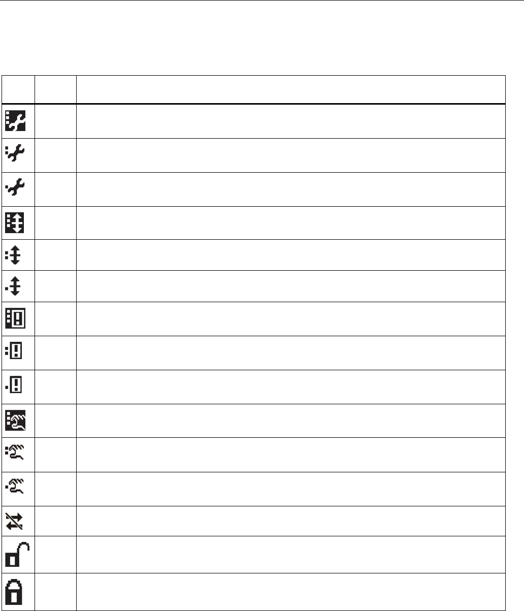
Diagnosing and troubleshooting
10.1 Device status icons
SITRANS LR250 (FOUNDATION FIELDBUS)
204 Operating Instructions, 08/2014, A5E32221411-AC
10.1
Device status icons
Icon
Priority
Level
Meaning
1 • Maintenance alarm
• Measurement values are not valid
2 • Maintenance warning: maintenance demanded immediately
• Measured signal still valid
3 • Maintenance required
• Measured signal still valid
1 • Process value has reached an alarm limit
2 • Process value has reached a warning limit
3 • Process value has reached a tolerance limit
1 • Configuration error
• Device will not work because one or more parameters/components is incorrectly configured
2 • Configuration warning
• Device can work but one or more parameters/components is incorrectly configured
3 • Configuration changed
• Device parameterization not consistent with parameterization in project. Look for info text.
1 • Manual operation (local override)
• Communication is good; device is in manual mode.
2 • Simulation or substitute value
• Communication is good; device is in simulation mode or works with substitute values.
3 • Out of operation
• Communication is good; device is out of action.
• No data exchange
• Write access enabled
• Write access disabled

Diagnosing and troubleshooting
10.2 General fault codes
SITRANS LR250 (FOUNDATION FIELDBUS)
Operating Instructions, 08/2014, A5E32221411-AC 205
10.2
General fault codes
Note
• If more than one fault is present, the device status indicator and text for each fault
alternate at 2 second intervals.
Code/
Icon
Meaning
Corrective Action
S: 0
The device was unable to get a measurement
within the Fail-safe LOE Timer period. Possible
causes: faulty installation, antenna material
buildup, foaming/other adverse process
conditions, invalid configuration range.
• Ensure installation details are correct.
• Ensure no antenna material buildup. Clean if necessary.
• Adjust process conditions to minimize foam or other
adverse conditions.
• Correct configuration range.
• If fault persists, contact your local Siemens
representative.
S: 2
Unable to collect profile because of a power
condition that is outside the operating range of
the device.
Repair required: contact your local Siemens representative.
S: 3
Device is nearing its lifetime limit as defined in
Remaining Lifetime (4.2.3.)
and has triggered a
Maintenance Required reminder (4.2.5.)
.
Replacement is recommended
S: 4
Device is nearing its lifetime limit as defined in
Remaining Lifetime (4.2.3.)
and has triggered a
Maintenance Demanded reminder (4.2.6.)
.
Replacement is recommended.
S: 6
Sensor is nearing its lifetime limit as defined in
Remaining Lifetime (4.3.3.)
and has triggered a
Maintenance Required reminder (4.3.5.)
.
Replacement is recommended.
S: 7
Sensor is nearing its lifetime limit as defined in
Remaining Lifetime (4.3.3.)
and has triggered a
Maintenance Demanded reminder (4.3.6.)
.
Replacement is recommended.
S: 8
Service interval (4.4.1.)
has expired and has
triggered a
Maintenance Required reminder
(4.4.5.)
.
Perform service.

Diagnosing and troubleshooting
10.2 General fault codes
SITRANS LR250 (FOUNDATION FIELDBUS)
206 Operating Instructions, 08/2014, A5E32221411-AC
Code/
Icon
Meaning
Corrective Action
S: 9
Service interval (4.4.1.)
has expired and has
triggered a
Maintenance Demanded reminder
(4.4.6.)
.
Perform service.
S: 10
Input parameters
Low Calibration Point (2.3.7.1.)
and
High Calibration Point (2.3.7.2.)
are the
same.
• Check calibration settings of device.
• Ensure settings for High Calibration Point and Low
Calibration Point are different.
S: 11
Internal temperature sensor failure. Repair required: contact your local Siemens representative.
S: 12
Internal temperature of device has exceeded
specifications: it is operating outside its
temperature range.
• Relocate device and/or lower process temperature
enough to cool device.
• Inspect for heat-related damage and contact your local
Siemens representative if repair is required.
• Fault code will persist until a manual reset is performed
using AMS or the LCD interface.
S: 17
Calibration interval (4.5.1.)
has
expired and has triggered a
Maintenance
Required reminder (4.5.5.)
.
Perform calibration.
S: 18
Calibration interval (4.5.1.)
has
expired and has triggered a
Maintenance
Demanded reminder (4.5.6.)
.
Perform calibration.
S: 22
Time Base Fault Hardware problem: contact your local Siemens
representative.
S: 28
Internal device failure caused by a RAM memory
error.
Repair required: contact your local Siemens representative.
S: 29
EEPROM damaged. Repair required: contact your local Siemens representative
S: 31
Flash error. Repair required: contact your local Siemens representative
S: 33
Factory calibration for the internal temperature
sensor has been lost.
Repair required: contact your local Siemens representative

Diagnosing and troubleshooting
10.2 General fault codes
SITRANS LR250 (FOUNDATION FIELDBUS)
Operating Instructions, 08/2014, A5E32221411-AC 207
Code/
Icon
Meaning
Corrective Action
S: 34
Factory calibration for the device has been lost. Repair required: contact your local Siemens representative
S: 35
Factory calibration for the device has been lost. Repair required: contact your local Siemens representative
S: 36
Unable to start microwave module. Repair required: contact your local Siemens representative
S: 37
Measurement hardware problem. Repair required: contact your local Siemens representative
S: 38
Microwave module hardware failure: unable to
calculate distance measurement.
Repair required: contact your local Siemens representative
S: 43
Factory calibration for the radar receiver has
been lost.
Repair required: contact your local Siemens representative.
S: 92
Corrupt Stack Contact your local Siemens representative and provide
configuration file and FB schedule.
S: 93
High Stack Contact your local Siemens representative and provide
configuration file and FB schedule.
S: 94
Data Safe Read Re-apply configuration and cycle power. If fault persists,
contact your local Siemens representative.
S: 95
Data Safe Write Re-apply configuration and cycle power. If fault persists,
contact your local Siemens representative.
S: 96
Safe Process Data Corrupt Contact your local Siemens representative and provide
configuration file and FB schedule.
S: 97
Board Voltage Hardware problem: contact your local Siemens
representative.

Diagnosing and troubleshooting
10.2 General fault codes
SITRANS LR250 (FOUNDATION FIELDBUS)
208 Operating Instructions, 08/2014, A5E32221411-AC
Code/
Icon
Meaning
Corrective Action
S: 98
ADC Failed Hardware problem: contact your local Siemens
representative.
S: 99
Prof. Clip Hardware problem. If fault persists contact your local
Siemens representative.
S: 100
Few Shots Hardware problem. If fault persists contact your local
Siemens representative.
S: 101
Meas. Err. Reset configuration. If fault persists contact your local
Siemens representative and provide configuration file and
FB schedule.
S: 102
No Shots Hardware problem. If fault persists contact your local
Siemens representative.
S: 103
Meas. Corrupt Contact your local Siemens representative and provide
configuration file and FB schedule.
S: 104
DMA Error Hardware problem. If fault persists contact your local
Siemens representative.
S: 105
Seq. Corrupt Contact your local Siemens representative and provide
configuration file and FB schedule.
S: 106
Seq. CP Re-install firmware (firmware upgrade). If fault persists
contact your local Siemens representative.
S: 107
Seq. Duration Increase update rate limit. If fault persists contact your local
Siemens representative.
S: 108
BC Corrupt Contact your local Siemens representative and provide
configuration file and FB schedule.
S: 109
BC Start Re-install firmware (firmware upgrade). If fault persists
contact your local Siemens representative.

Diagnosing and troubleshooting
10.2 General fault codes
SITRANS LR250 (FOUNDATION FIELDBUS)
Operating Instructions, 08/2014, A5E32221411-AC 209
Code/
Icon
Meaning
Corrective Action
S: 110
BC Stop Re-install firmware (firmware upgrade). If fault persists
contact your local Siemens representative.
S: 111
BC Duration Hardware problem. If fault persists contact your local
Siemens representative.
S: 112
CPU Fault Hardware problem. If fault persists contact your local
Siemens representative.
S: 113
Data Bus Hardware problem. If fault persists contact your local
Siemens representative.
S: 114
Addr Bus Hardware problem. If fault persists contact your local
Siemens representative.
S: 115
Spur SW Hardware problem. If fault persists contact your local
Siemens representative.
S: 116
Spur HW Hardware problem. If fault persists contact your local
Siemens representative.
S: 117
SV High Verify TB not in simulation mode. If fault persists contact
your local Siemens representative.
S: 118
SV Low Verify TB not in simulation mode. If fault persists contact
your local Siemens representative.

Diagnosing and troubleshooting
10.3 Operation troubleshooting
SITRANS LR250 (FOUNDATION FIELDBUS)
210 Operating Instructions, 08/2014, A5E32221411-AC
10.3
Operation troubleshooting
Operating symptoms, probable causes, and resolutions.
Symptom
Cause
Action
Display shows
level or target is out of range • check specifications
• check
Low Calibration Pt. (2.3.7.1.)
• increase
Confidence (2.5.9.1.)
Display shows
material build-up on antenna • clean the antenna
• re-locate SITRANS LR250
Display shows
location or aiming:
• poor installation
• flange not level
• Auto False Echo Suppression
may be incorrectly applied
• check to ensure nozzle is vertical
• ensure end of antenna protrudes from end of nozzle
• review Auto False Echo Suppression (Page 271)
• ensure Auto False Echo Suppression Range is set
correctly
Display shows
antenna malfunction:
• temperature too high
• physical damage
• excessive foam
• multiple echoes
• check temperature in
Maximum Value (3.3.2.)
• use foam deflector or stillpipe
• relocate
• use a defoamer
• set
Algorithm (2.5.7.1.)
to t
F
(trueFirst echo)
Reading does not
change, but the level
does
SITRANS LR250 processing
wrong echo, for example, vessel
wall, or structural member
• re-locate SITRANS LR250
• check nozzle for internal burrs or welds
• rotate device 90°
• use
Auto False Echo Suppression (2.5.10.1.)
• if necessary: see Auto False Echo Suppression
(Page 271)
Measurement is
consistently off by a
constant amount
• setting for
Low Calibration
Point (2.3.7.1.)
not correct
• setting for
Sensor Offset
(2.3.7.3.)
not correct
• check distance from sensor reference point to
Low
Calibration Point (2.3.7.1.)
• check
Sensor Offset (2.3.7.3.)
Screen blank power error • check nameplate rating against voltage supply
• check power wiring or source
too much load resistance • change barrier type, or
• remove something from the loop, or
• increase supply voltage
• reduce wire distance or use larger gage wire

Diagnosing and troubleshooting
10.3 Operation troubleshooting
SITRANS LR250 (FOUNDATION FIELDBUS)
Operating Instructions, 08/2014, A5E32221411-AC 211
Symptom
Cause
Action
Reading erratic echo confidence weak • refer to
Confidence (2.5.9.1.)
• use
Auto False Echo Suppression (2.5.10.1.)
and
Auto
False Echo Suppression Range (2.5.10.2.)
• use foam deflector or stillpipe
liquid surface vortexed • decrease
Fill Rate (2.3.8.2..)
• relocate device to side pipe
• increase confidence threshold in
Echo Threshold (2.5.7.3.)
material filling • Re-locate SITRANS LR250
Reading response
slow
Fill Rate (2.3.8.2.)
setting
incorrect
• increase measurement response if possible
Reads correctly but
occasionally reads
high when vessel is
not full
• detecting close range echo
• build up near top of vessel or
nozzle
• nozzle problem
• clean the antenna
• use
Auto False Echo Suppression (2.5.10.1.)
and
Auto
False Echo Suppression Range (2.5.10.2.)
Level reading lower
than actual material
level
• material is within Near Range
zone
• multiple echoes processed
• decrease
Near Range (2.5.1.)
(minimum value depends on
antenna type)
• raise SITRANS LR250
• ensure
Algorithm (2.5.7.1.)
is set to t
F
(First echo)
• vessel near empty and low
dK material
• ensure
Material (1.2.)
selection is LIQUID LOW DK
• set
Position Detect (2.5.7.2.)
to
Hybrid
• check the setting for
CLEF Range (2.5.7.4.):
see the table
below
Propogation Factor (2.5.3.)
for recommended
settings
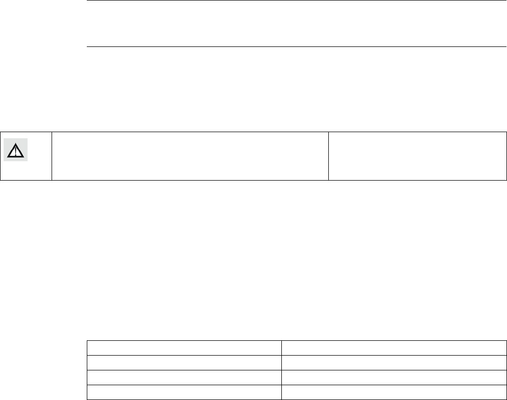
SITRANS LR250 (FOUNDATION FIELDBUS)
Operating Instructions, 08/2014, A5E32221411-AC 213
Technical data
11
Note
• Siemens makes every attempt to ensure the accuracy of these specifications but
reserves the right to change them at any time.
11.1
Power
General Purpose
Intrinsically Safe
Non-Sparking
Non-incendive (FM/CSA US/Canada only)
9-32 V DC
Bus powered 9-32 V DC, per IEC 61158-2 (Foundation Fieldbus)
Current consumed 20 mA
11.2
Performance
Reference operating conditions according to IEC 60770-1
Ambient temperature 15 to 25 °C (59 to 77 °F)
Humidity 45 to 75% relative humidity
Ambient pressure 860 to 1060 mbar a (86000 to 106000 N/m2 a)
Interference reflections minimum 20 dB lower than the main target reflection

Technical data
11.2 Performance
SITRANS LR250 (FOUNDATION FIELDBUS)
214 Operating Instructions, 08/2014, A5E32221411-AC
Measurement Accuracy (measured in accordance with IEC 60770-1)
Maximum measured error =3 mm (0.12")1) 2) 3) including hysteresis and non-
repeatability
Frequency K-band
Maximum measurement range4) 1.5" antenna 10 m (32.8 ft)5)
2" threaded PVDF antenna
2"/DN50/50A Flangedencapsulated
antenna (FEA)
2" ISO 2852, DN50 DIN11864-1/2/3,
DN50 DIN11851,Tuchenhagen
Types F and N Hygienic
encapsulated antenna (HEA)
all other versions 20 m (65.6 ft)
Minimum detectable distance 50 mm (2") from end of antenna6)
Update time7) minimum 1 second, depending on settings for
Response Rate (2.3.8.1.)
and
LCD Fast Mode (4.9.).
Influence of ambient temperature < 0.003% / K (average over full temperature range,
referenced to maximum range)
Dielectric constant of material measured dK > 1.6 [antenna and application dependent8)]
Memory non-volatile EEPROM
no battery required
1) The statistical accuracy is typically 3 mm (0.12") 90% of the time, when tested in accordance
with IEC 60770-1.
2) Under severe EMI/EMC environments per IEC 61326-1 or NAMUR NE21, the device error
may increase to a maximum of 10 mm (0.4").
3) For 2" threaded PVDF antenna, Flanged encapsulated antennas and Hygienic encapsulated
antennas, the maximum measured error <500 mm from the sensor reference point =25 mm (1").
4) From sensor reference point: see Dimension drawings (Page 221) and Flanged Horn with
extension (Page 228).
5) 20 m (65.6 ft) possible in a stillpipe/bypass
6) Minimum range is antenna length +50 mm (2"). See Dimension drawings (Page 221).
7) Reference conditions:
Response Rate (2.4.1.)
set to
FAST, LCD Fast Mode (4.9.)
set to
ON
.
8) For 1.5" (40 mm) antenna and 2" (50 mm) threaded PVDF antenna, 2"/DN50/50A flanged
encapsulated antenna and 2" ISO 2852, DN50 DIN 11864-1/2/3, DN50 DIN11851, Tuchenhagen
Types F and N hygienic encapsulated antenna the minimum dK is limited to 3 unless a stillpipe
is used.

Technical data
11.3 Interface
SITRANS LR250 (FOUNDATION FIELDBUS)
Operating Instructions, 08/2014, A5E32221411-AC 215
11.3
Interface
Communication: Foundation Fieldbus
ITK version 5 Blocks supported:
RESOURCE, LTB, AIFB1, AIFB2, LCD, DIAG
Block execution time:
AIFB - 40 ms
Configuration Remote FF host system or Emerson AMS (PC)
Local Siemens Milltronics infrared handheld programmer [see Programmer (infrared
keypad) (Page 220), or Field Communicator 375 (Page 291)]
Display (local)1) graphic LCD, with bar graph (representing level)
1)
Display quality will be degraded in temperatures below –25 °C (–13 °F) and above +65 °C (+149 °F).
11.4
Mechanical
Process
connection:
Threaded connection 1.5" NPT (ASME B1.20.1), R (BSPT, EN 10226-1) a) or
G (BSPP, EN ISO 228-1)
or 2" NPT (ASME B1.20.1), R (BSPT, EN 10226-1) or
G (BSPP, EN ISO 228-1)
or 3" NPT (ASME B1.20.1), R (BSPT, EN 10226-1) or
G (BSPP, EN ISO 228-1)
Flange connection (flat-face)
Materials
2", 3", 4" (ASME 150 lb, 300 lb)
DN50, DN80, DN100 (PN 10/16, PN 25/40)
50A, 80A, 100A (JIS 10K)
316L /1.4404 or 316L /1.4435 stainless steel
Flange connection (raised face)
Materials
DN50, DN80, DN100, DN150 (PN 10/16, PN 25/40)
1.4404 or 1.4435 stainless steel, optional Alloy
N06022/2.4602 (Hastelloy®C-22 or equivalent)
Flanged encapsulated antenna (FEA)
connection (raised face)
Materials
2, 3, 4, 6" (ASME 150 lb); DN50, DN80, DN100,
DN150 (PN10/16); 50A, 80A, 100A, 150A (JIS 10K)
316L /1.4404 or 316L /1.4435 stainless steel
Hygienic encapsulated antenna (HEA)
connection
ISO 2852 (2, 3, 4")
DIN 11851 (DN50, DN80, DN100)
DIN 11864-1/2/3 (DN50, DN80, DN100)
Tuchenhagen (Type F [50 mm and Type N [68 mm])
316L /1.4404 or 316L /1.4435 stainless steel

Technical data
11.4 Mechanical
SITRANS LR250 (FOUNDATION FIELDBUS)
216 Operating Instructions, 08/2014, A5E32221411-AC
Materials
ISO 2852 (2, 3, 4")
DIN 11864-3 (DN50,
DN80, DN100)
clamp: 304/1.4301
stainless steel
Tuchenhagen (Type F
[50 mm] and Type
N [68 mm])
316L /1.4404 or
316L /1.4435 stainless
steel
clamp: 304/1.4301
stainless steel
nut connection:
303/1.4305 stainless steel
DIN 11851/11864-1
(DN50, DN80. DN100)
captive slotted nut
connection: 304L/1.4307
DIN 11864-2 (DN50,
DN80. DN100)
mounting nuts and bolts:
304/1.4301 stainless steel
Antenna: Horn
Materials
standard 1.5" (40 mm), 2" (50 mm), 3" (80 mm), and
4" (100 mm) horn, optional 100 mm (4") horn
extension
316L stainless steel with PTFE emitter
optional Alloy N06022/2.4602 (Hastelloy®C-22 or
equivalent) with PTFE emitter
Threaded PVDF antenna
Wetted materials
2" (50 mm)
PVDF (Polyvinylidene fluoride)
Flanged encapsulated antenna
Wetted materials
316L /1.4404 or 316L /1.4435 stainless steel
TFMTM 1600 PTFE lens
Hygienic encapsulated antenna
Wetted material
316L/1.4404 or 316L/1.4435 stainless steel
TFMTM 1600 PTFE (plus chosen seal)
Enclosure Construction aluminum, polyester powder-coated
Conduit entry 2 x M20x1.5, or 2 x ½" NPT
Ingress protection Type 4X/NEMA 4X, Type 6/NEMA 6, IP67, IP68
Weight (excluding
extensions):
1.5" threaded connection with 1.5" horn
antenna
approximately 5.1 kg (11.2 lb)
2" threaded connection with 2" horn
antenna
approximately 5.5 kg (12.1 lb)
3" threaded connection with 3" horn
antenna
approximately 7.0 kg (15.4 lb)
2" threaded PVDF antenna approximately 3.3 kg (7.27 lb)
DN50 PN 10/16 or 2" 150 lb flat-face flange
with 2" horn antenna
approximately 8 kg (17.6 lb)
DN100 PN 25/40 or 4" ASME 300 lb flat-
face flange with 4" horn antenna
approximately 17.4 kg (38.3 lb)
DN50 PN 10/16 raised-face flange with 2"
horn antenna
approximately 6 kg (13.2 lb)

Technical data
11.4 Mechanical
SITRANS LR250 (FOUNDATION FIELDBUS)
Operating Instructions, 08/2014, A5E32221411-AC 217
DN100 PN 25/40 raised-face flange with 4"
horn antenna
approximately 11.3 kg (24.9 lb)
2" ASME 150 lb FEA approximately 7.0 kg (15.4 lb)
3" ASME 150 lb FEA approximately 10.7 kg (23.6 lb)
4" ASME 150 lb FEA approximately 13.1 kg (28.9 lb)
6" ASME 150 lb FEA approximately 17.7 kg (39 lb)
DN50 PN 10/16 FEA approximately 7.1 kg (15.7 lb)
DN80 PN 10/16 FEA approximately 10.1 kg (22.3 lb)
DN100 PN 10/16 FEA approximately 11.1 kg (24.5 lb)
DN150 PN 10/16 FEA approximately 15.9 kg (35.1 lb)
50 A JIS 10K FEA approximately 6.5 kg (14.3 lb)
80 A JIS 10K FEA approximately 9 kg (19.8 lb)
100 A JIS 10K FEA approximately 10.1 kg (22.3 lb)
150 A JIS 10K FEA approximately 16.3 kg (35.9 lb)
2" ISO 2852 HEA approximately 4.7 kg (10.4 lb)
3" ISO 2852 HEA approximately 6.3 kg (13.9 lb)
4" ISO 2852 HEA approximately 6.8 kg (15 lb)
DN50 DIN 11864-1 HEA approximately 4.8 kg (10.6 lb)
DN80 DIN 11864-1 HEA approximately 6.7 kg (14.8 lb)
DN100 DIN 11864-1 HEA approximately 7.1 kg (15.7 lb)
DN50 DIN 11864-2 HEA approximately 5.0 kg (11 lb)
DN80 DIN 11864-2 HEA approximately 7.2 kg (15.9 lb)
DN100 DIN 11864-2 HEA approximately 7.9 kg (17.4 lb)
DN50 DIN 11864-3 HEA approximately 4.8 kg (10.6 lb)
DN80 DIN 11864-3 HEA approximately 6.6 kg (14.6 lb)
DN100 DIN 11864-3 HEA approximately 7.2 kg (15.9 lb)
DN50 DIN 11851 HEA approximately 4.8 kg (10.6 lb)
DN80 DIN 11851 HEA approximately 6.8 kg (15 lb)
DN100 DIN 11851 HEA approximately 7.2 kg (15.9 lb)
Tuchenhagen Type F HEA approximately 4.8 kg (10.6 lb)
Tuchenhagen Type N HEA approximately 4.9 kg (10.8 lb)
a)
For use with 1.5" (40 mm) horn antennas only.

Technical data
11.5 Environmental
SITRANS LR250 (FOUNDATION FIELDBUS)
218 Operating Instructions, 08/2014, A5E32221411-AC
11.5
Environmental
Note
• For the specific configuration you are about to use or install, check transmitter nameplate
and see Approvals (Page 219).
• Use appropriate conduit seals to maintain IP or NEMA rating.
Location indoor/ outdoor
Altitude 5000 m (16,404 ft) max.
Ambient temperature −40 to +80 °C (−40 to +176 °F)
Relative humidity suitable for outdoor
Type 4X/NEMA 4X, Type 6/NEMA 6, IP67, IP68 enclosure (see note
above)
Installation category I
Pollution degree 4
11.6
Process
Note
The maximum temperature is dependent on the process connection, antenna materials, and
vessel pressure. For more detailed information see Maximum Process Temperature Chart
(Page 274) and Process Pressure/Temperature derating curves (Page 276).
Temperature at process
connection
Standard Horn antenna
(Threaded or Flanged):
with FKM O-ring −40 to +200 °C (−40 to +392 °F)
with FFKM O-ring −20 to +200 °C (−4 to +392 °F)
2" NPT / BSPT / G Threaded PVDF antenna: −40 to +80 °C (−40 to +176 °F)
Flanged encapsulated antenna (FEA) -40 to +170 °C (−40 to +338 °F)
Hygienic encapsulated antenna (HEA) -40 to +170 °C (−40 to +338 °F)
with FKM seals used on process
connection: -20 to +170 °C (-4 to +338
°F)
with EPDM seals used on process
connection: -40 to +120 °C (-40 to +248
°F)
Pressure (vessel) Refer to process connection tag and
Process Pressure/Temperature derating
curves (Page 276).

Technical data
11.7 Approvals
SITRANS LR250 (FOUNDATION FIELDBUS)
Operating Instructions, 08/2014, A5E32221411-AC 219
11.7
Approvals
Note
The device nameplate lists the approvals that apply to your device.
Application type
LR250 version
Approval rating
Valid for:
Non-hazardous
General purpose CSAUS/C, FM, CE, RCM N. America,
Europe
Radio Europe (R&TTE), FCC, Industry Canada
Hazardous
Intrinsically safe
(Page 48)
ATEX II 1G, Ex ia IIC T4 Ga
ATEX II 1D, Ex ia ta IIIC T100 °C Da
Europe
IECEx SIR 09.0148X, Ex ia IIC T4 Ga
Ex ia ta IIIC T100 °C Da
International
FM/CSA
Class I, Div. 1, Groups A, B, C, D
Class II, Div. 1, Groups E, F, G
Class III T4
US/Canada
INMETRO DNV 12.0090 X
Ex ia IIC T4 Ga
Ex ia ta IIIC T100 ºC Da IP65/IP67
-40 °C ≤ Ta ≤ +80 °C
DNV #OCP 0017
ABNT NBR IEC 60079-0:2008,
ABNT NBR IEC 60079-11:2009,
ABNT NBR IEC 60079-26:2008
e ABNT NBR IEC 60079-31:2011
Brazil
NEPSI Ex ia IIC T4 Ga
Ex iaD 20 T90 IP6X DIP A20 TA 90ºC
China
Non-Sparking
(Page 51)
ATEX II 3 G, Ex nA IIC T4 Gc Europe
NEPSI Ex nA IIC T4 Gc China
Non-incendive
(Page 51)
FM/CSA
Class I, Div. 2, Groups A, B, C, D T5
US/Canada
Marine Lloyd's Register of Shipping
ABS Type Approval
BV Type Approval
Hygienic/Sanitary
EHEDG EL Class I
EHEDG EL Class I Aseptic
International
3-A Sanitary Standards

Technical data
11.8 Programmer (infrared keypad)
SITRANS LR250 (FOUNDATION FIELDBUS)
220 Operating Instructions, 08/2014, A5E32221411-AC
11.8
Programmer (infrared keypad)
Note
Battery is non-replaceable with a lifetime expectancy of 10 years in normal use.
To estimate the lifetime expectancy, check the nameplate on the back for the serial number.
The first six numbers show the production date (mmddyy), for example, serial number
032608101V was produced on March 26, 2008.
Siemens Milltronics Infrared IS (Intrinsically Safe) Handheld Programmer for hazardous and all
other locations (battery is non-replaceable).
Approvals CE
FM/CSA Class I, II, III, Div. 1, Gr. A to G T6
ATEX II 1GD Ex ia IIC T4 Ga
Ex iaD 20 T135 °C
IECEx Ex ia IIC T4 Ga
Ex iaD 20 T135 °C
INMETRO Ex ia IIC T4 Ga
Ex ia IIIC T135 °C Da
Ambient temperature −20 to +50 °C (−5 to +122 °F)
Interface proprietary infrared pulse signal
Power 3 V non-replaceable lithium battery
Weight 150 g (0.3 lb)
Color black
Part number 7ML1930-1BK

SITRANS LR250 (FOUNDATION FIELDBUS)
Operating Instructions, 08/2014, A5E32221411-AC 221
Dimension drawings
12
12.1
Threaded horn antenna
Note
• Process temperature and pressure capabilities are dependent upon information on the
process connection tag. Reference drawing listed on the tag is available for download
from our website under
Support/Installation drawings/Level Measurement/Continuous -
Radar/LR250
:
Product page (http://www.siemens.com/LR250)
• Process connection drawings are also available for download from the
Installation
Drawings page
.
• Signal amplitude increases with horn diameter, so use the largest practical size.
• Optional extensions can be installed below the threads.
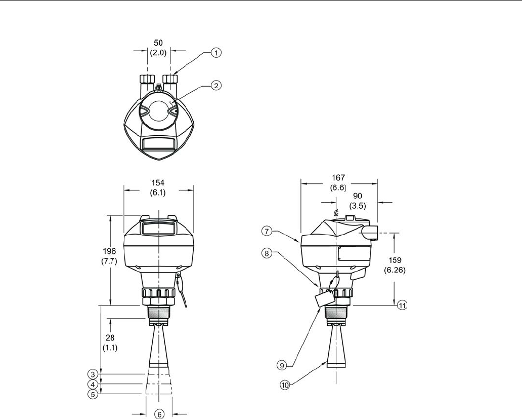
Dimension drawings
12.1 Threaded horn antenna
SITRANS LR250 (FOUNDATION FIELDBUS)
222 Operating Instructions, 08/2014, A5E32221411-AC
①
½" NPT cable entry, or M20 cable gland
⑦
enclosure/electronics
②
threaded cover
⑧
retaining collar
③
2" horn
⑨
process connection tag
④
3" horn
⑩
horn
⑤
4" horn
⑪
sensor reference point
⑥
horn O.D.
Dimensions in mm (inch)

Dimension drawings
12.1 Threaded horn antenna
SITRANS LR250 (FOUNDATION FIELDBUS)
Operating Instructions, 08/2014, A5E32221411-AC 223
Threaded horn dimensions
Antenna
Type
Antenna
O.D.
in mm
(inch)
Height to sensor reference point, in mm (inch) a)
Beam Angle
(°)b)
Measurement
range, in m (ft)
1-1/2" threaded
connection
2" threaded
connection
3" threaded
connection
1.5" 39.8 (1.57) 135 (5.3) N/A N/A 19 10 (32.8)
2" 47.8 (1.88) N/A 166 (6.55) 180 (7.09) 15 20 (65.6)
3" 74.8 (2.94) N/A 199 (7.85) 213 (8.39) 10 20 (65.6)
4" 94.8 (3.73) N/A 254 (10) 268 (10.55) 8 20 (65.6)
a) Height from bottom of horn to sensor reference point as shown: see dimension drawing.
b) -3dB in the direction of the polarization axis. For an illustration, see Polarization reference point
(Page 31).
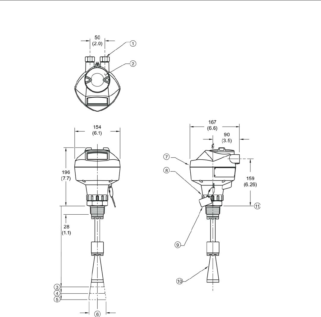
Dimension drawings
12.2 Threaded horn antenna with extension
SITRANS LR250 (FOUNDATION FIELDBUS)
224 Operating Instructions, 08/2014, A5E32221411-AC
12.2
Threaded horn antenna with extension
①
½" NPT cable entry, or M20 cable gland
⑦
enclosure/electronics
②
threaded cover
⑧
retaining collar
③
2" horn
⑨
process connection tag
④
3" horn
⑩
horn
⑤
4" horn
⑪
sensor reference point
⑥
horn O.D.
Dimensions in mm (inch)

Dimension drawings
12.2 Threaded horn antenna with extension
SITRANS LR250 (FOUNDATION FIELDBUS)
Operating Instructions, 08/2014, A5E32221411-AC 225
Threaded horn with extension dimensions
Antenna
Type
Antenna
O.D.
in mm
(inch)
Height to sensor reference point, in mm (inch) a)
Beam Angle
(°) b)
Measurement
range
in m (ft)
1-1/2" threaded
connection
2" threaded
connection
3" threaded
connection
1.5" 39.8 (1.57) 235 (9.25) N/A N/A 19 10 (32.8)
2" 47.8 (1.88) N/A 266 (10.47) 280 (11.02) 15 20 (65.6)
3" 74.8 (2.94) N/A 299 (11.77) 313 (12.32) 10 20 (65.6)
4" 94.8 (3.73) N/A 354 (13.94) 368 (14.49) 8 20 (65.6)
a) Height from bottom of horn to sensor reference point as shown: see dimension drawing.
b) -3dB in the direction of the polarization axis. For an illustration, see Polarization reference point
(Page 31).
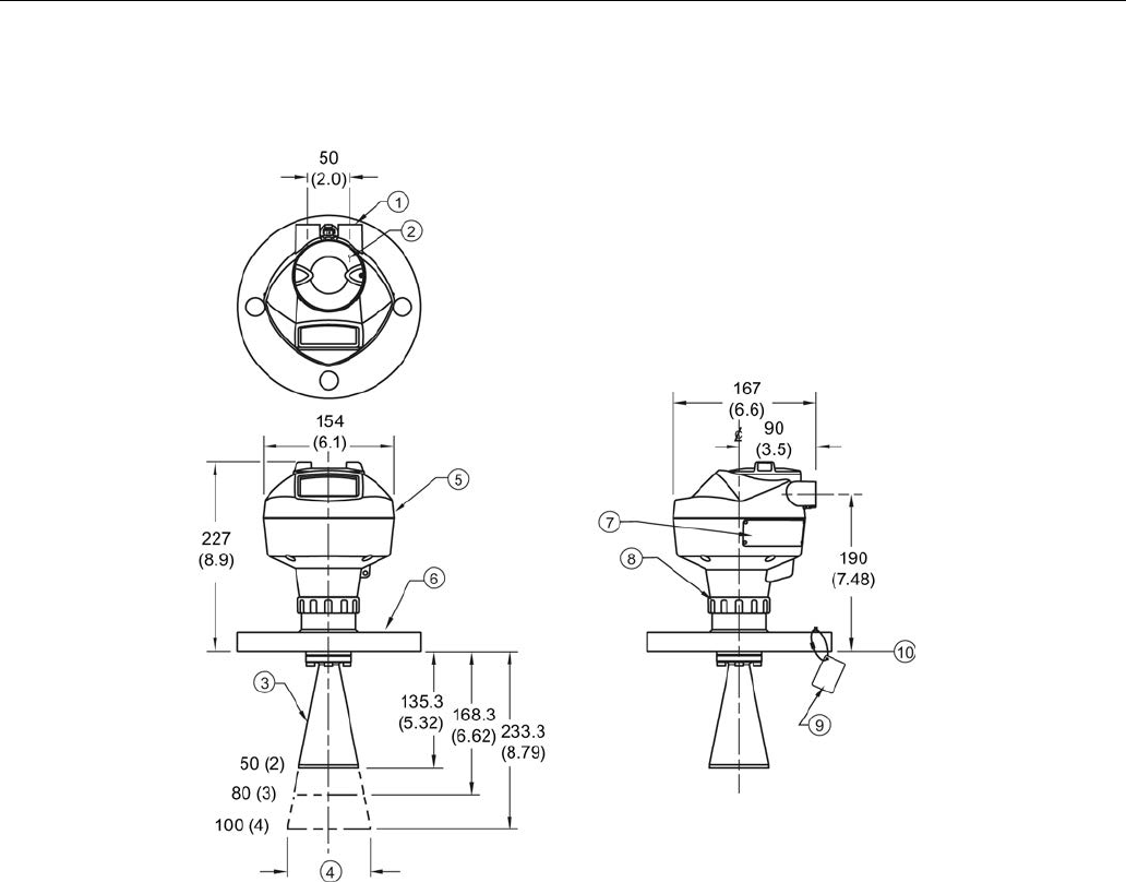
Dimension drawings
12.3 Flanged horn antenna
SITRANS LR250 (FOUNDATION FIELDBUS)
226 Operating Instructions, 08/2014, A5E32221411-AC
12.3
Flanged horn antenna
①
½" NPT cable entry, or M20 cable gland
⑥
flange
②
threaded cover
⑦
name-plate
③
horn
⑧
retaining collar
④
horn O.D.
⑨
process connection tag
⑤
enclosure/electronics
⑩
sensor reference point
Dimensions in mm (inch)

Dimension drawings
12.3 Flanged horn antenna
SITRANS LR250 (FOUNDATION FIELDBUS)
Operating Instructions, 08/2014, A5E32221411-AC 227
Flanged Horn dimensions
Nominal horn
size
in mm (inch)
Horn O.D.
in mm (inch)
Height to sensor reference point, in mm
(inch)a)
Beam angle
(°)b)
Measurement range,
in m (ft)
Stainless steel flange:
raised or flat-face
Optional alloy
flange c)
50 (2) 47.8 (1.88) 135.3 (5.32) 138.3 (5.44) 15
20 (65.6)
80 (3) 74.8 (2.94) 168.3 (6.62) 171.3 (6. 74) 10
100 (4) 94.8 (3.73) 223.3 (8.79) 226.3 (8.90) 8
a)Height from bottom of horn to sensor reference point as shown: see Flanged horn antenna with
extension (Page 228). See also Raised-Face flange per EN 1092-1 for flanged horn antenna
(Page 253), or Flat-Face flange (Page 258).
b) -3dB in the direction of the polarization axis (see Polarization reference point (Page 31) for an
illustration).
c) Optional alloy N06022/2.4602 (Hastelloy® C-22 or equivalent). See Raised-Face Flange
Dimensions (Page 253).
Note
Heights to sensor reference point are for stainless steel flanges. For optional alloy
N06022/2.4602 (Hastelloy© C-22 or equivalent) see Flanged Horn dimensions above.
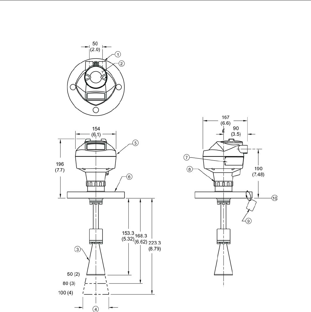
Dimension drawings
12.4 Flanged horn antenna with extension
SITRANS LR250 (FOUNDATION FIELDBUS)
228 Operating Instructions, 08/2014, A5E32221411-AC
12.4
Flanged horn antenna with extension
①
½" NPT cable entry, or M20 cable gland
⑥
flange
②
threaded cover
⑦
name-plate
③
horn
⑧
retaining collar
④
horn O.D.
⑨
process connection tag
⑤
enclosure/electronics
⑩
sensor reference point
Dimensions in mm (inch)

Dimension drawings
12.4 Flanged horn antenna with extension
SITRANS LR250 (FOUNDATION FIELDBUS)
Operating Instructions, 08/2014, A5E32221411-AC 229
Flanged horn with extension dimensions
Nominal horn
size
in mm (inch)
Horn O.D. in mm
(inch)
Height to sensor reference point,, in mm
(inch) a)
Beam angle
(°)b)
Measurement range,
in m (ft)
Stainless steel flange:
raised or flat-face
Optional alloy
flange c)
50 (2) 47.8 (1.88) 235.3 (9.26) 238.3 (9.38) 15
20 (65.6)
80 (3) 74.8 (2.94) 268.3 (10.56) 271.3 (10.68) 10
100 (4) 94.8 (3.73) 323.3 (12.73) 326.3 (12.85) 8
a)Height from bottom of horn to sensor reference point as shown: See also Flanged horn
antenna (Page 226) or Flat-Face Flange. (Page 258)
b) -3dB in the direction of the polarization axis (see Polarization reference point (Page 31) for an
illustration).
c) Optional alloy N06022/2.4602 (Hastelloy® C-22 or equivalent). See Raised-Face flange per EN
1092-1 for flanged horn antenna (Page 253).
Note
Heights to sensor reference point are for stainless steel flanges. For optional alloy
N06022/2.4602 (Hastelloy© C-22 or equivalent) see Flanged Horn dimensions above.
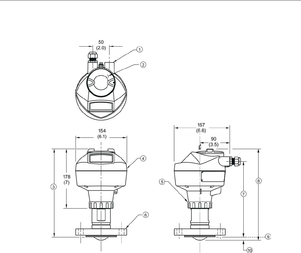
Dimension drawings
12.5 Flanged encapsulated antenna (2"/DN50/50A sizes only)
SITRANS LR250 (FOUNDATION FIELDBUS)
230 Operating Instructions, 08/2014, A5E32221411-AC
12.5
Flanged encapsulated antenna (2"/DN50/50A sizes only)
①
½" NPT cable entry, or M20 cable gland
⑥
flange
②
threaded cover
⑦
see table below
③
see table below
⑧
see table below
④
enclosure
⑨
sensor reference point
⑤
retaining collar
⑩
see table below
Dimensions in mm (inch)

Dimension drawings
12.5 Flanged encapsulated antenna (2"/DN50/50A sizes only)
SITRANS LR250 (FOUNDATION FIELDBUS)
Operating Instructions, 08/2014, A5E32221411-AC 231
Flanged encapsulated antenna (2"/DN50/50A) dimensions
Flange size
③ mm (inch)
⑦ mm (inch)
⑧ mm (inch)
⑩ mm (inch)1)
2"/DN50/50A 263 (10.35) 223 (8.78) 274 (10.79) 11 (0.43)
1) Height from tip of lens to sensor reference point as shown.
Flange size
Flange class
Flange O.D.
[mm (inch)]
Antenna
aperture size
[mm (inch)]
Beam angle
(°)1)
Measurement
range
[m (ft)]
2" 150 LB 152 (5.98) 50 (1.97) 12.8 10 (32.8)2)
DN50 PN10/16 165 (6.50)
50A 10K 155 (6.10)
1) -3 dB in the direction of the polarization axis.
2) 20m if installed in stillpipe
See Raised-Face Flange per EN 1092-1, (Page 255)and Polarization reference point (Page 31).
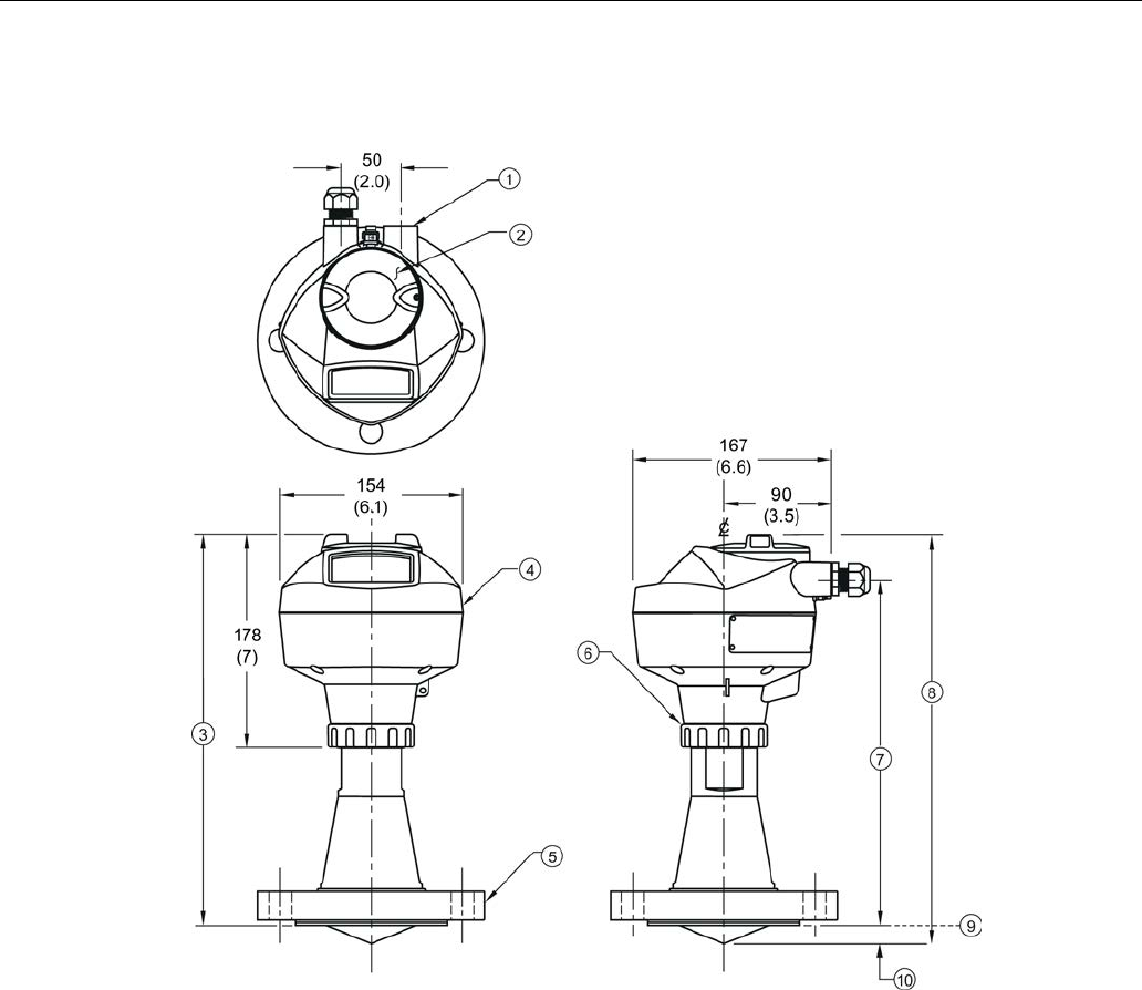
Dimension drawings
12.6 Flanged encapsulated antenna (3"/DN80/80A sizes and larger)
SITRANS LR250 (FOUNDATION FIELDBUS)
232 Operating Instructions, 08/2014, A5E32221411-AC
12.6
Flanged encapsulated antenna (3"/DN80/80A sizes and larger)
①
½" NPT cable entry, or M20 cable gland
⑥
retaining collar
②
threaded cover
⑦
see table below
③
see table below
⑧
see table below
④
enclosure
⑨
sensor reference point
⑤
flange
⑩
see table below
Dimensions in mm (inch)

Dimension drawings
12.6 Flanged encapsulated antenna (3"/DN80/80A sizes and larger)
SITRANS LR250 (FOUNDATION FIELDBUS)
Operating Instructions, 08/2014, A5E32221411-AC 233
Flanged encapsulated antenna (3"/DN80/80A and larger) dimensions
Flange size
③ mm (inch)
⑦ mm (inch)
⑧ mm (inch)
⑩ mm (inch)1)
3"/DN80/80A 328 (12.91) 288 (11.34) 343 (13.50) 15 (0.59)
4"/DN100/100A 328 (12.91) 288 (11.34) 343 (13.50) 13 (0.51)
6"/DN150/150A 333 (13.11) 293 (11.54) 348 (13.70) 15 (0.59)
1) Height from tip of lens to sensor reference point as shown. See also Raised-Face Flange per EN
1092-1.
Flange size
Flange class
Flange O.D.
[mm (inch)]
Antenna
aperture size
[mm (inch)]
Beam angle
(°)1)
Measurement
range
[m (ft)]
3" 150 LB 190 (7.48) 75 (2.95) 9.6 20 (65.6)
DN80 PN10/16 200 (7.87)
80A 10K 185 (7.28)
4" 150 LB 230 (9.06) 75 (2.95) 9.6 20 (65.6)
DN100 PN10/16 220 (8.66)
100A 10K 210 (8.27)
6" 150 LB 280 (11.02) 75 (2.95) 9.6 20 (65.6)
DN150 PN10/16 285 (11.22)
150A 10K 280 (11.02)
1)
-3 dB in the direction of the polarization axis.
See Raised-Face Flange per EN 1092-1 (Page 255), and Polarization reference point (Page 31).
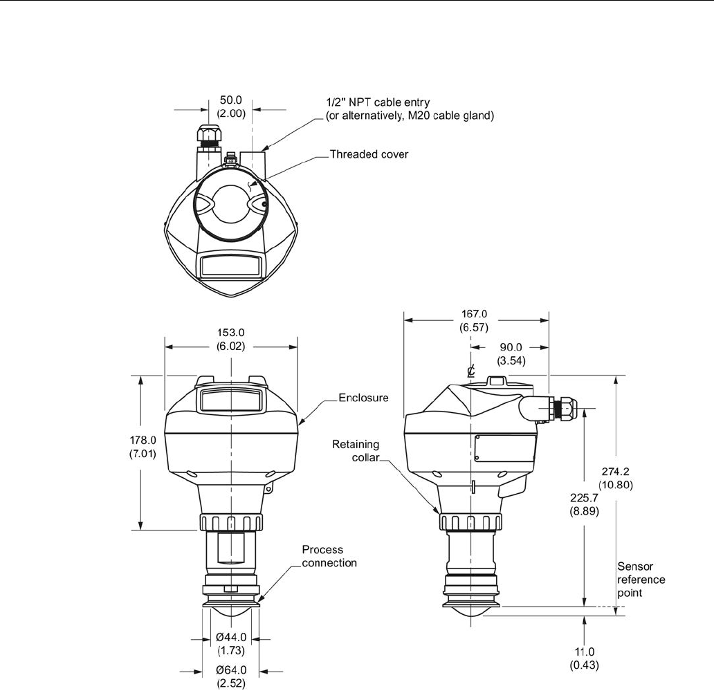
Dimension drawings
12.7 Hygienic encapsulated antenna (2" ISO 2852 sanitary clamp)
SITRANS LR250 (FOUNDATION FIELDBUS)
234 Operating Instructions, 08/2014, A5E32221411-AC
12.7
Hygienic encapsulated antenna (2" ISO 2852 sanitary clamp)
Dimensions in mm (inch)
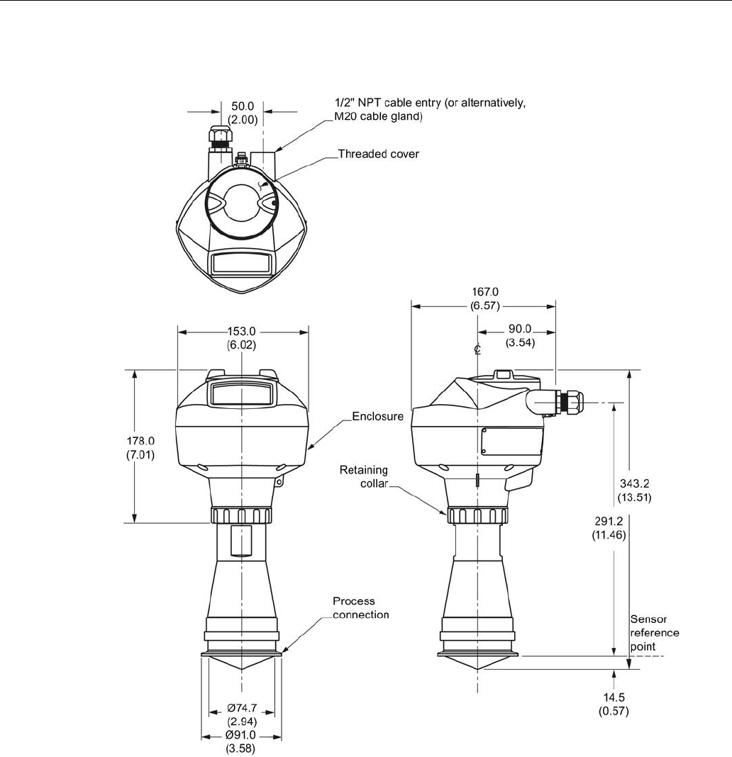
Dimension drawings
12.8 Hygienic encapsulated antenna (3" ISO 2852 sanitary clamp)
SITRANS LR250 (FOUNDATION FIELDBUS)
Operating Instructions, 08/2014, A5E32221411-AC 235
12.8
Hygienic encapsulated antenna (3" ISO 2852 sanitary clamp)
Dimensions in mm (inch)
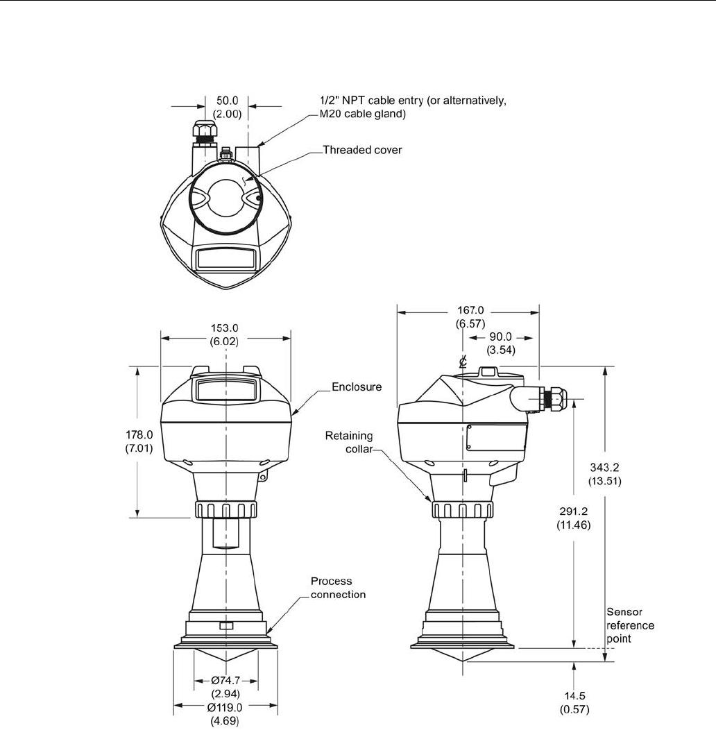
Dimension drawings
12.9 Hygienic encapsulated antenna (4" ISO 2852 sanitary clamp)
SITRANS LR250 (FOUNDATION FIELDBUS)
236 Operating Instructions, 08/2014, A5E32221411-AC
12.9
Hygienic encapsulated antenna (4" ISO 2852 sanitary clamp)
Dimensions in mm (inch)
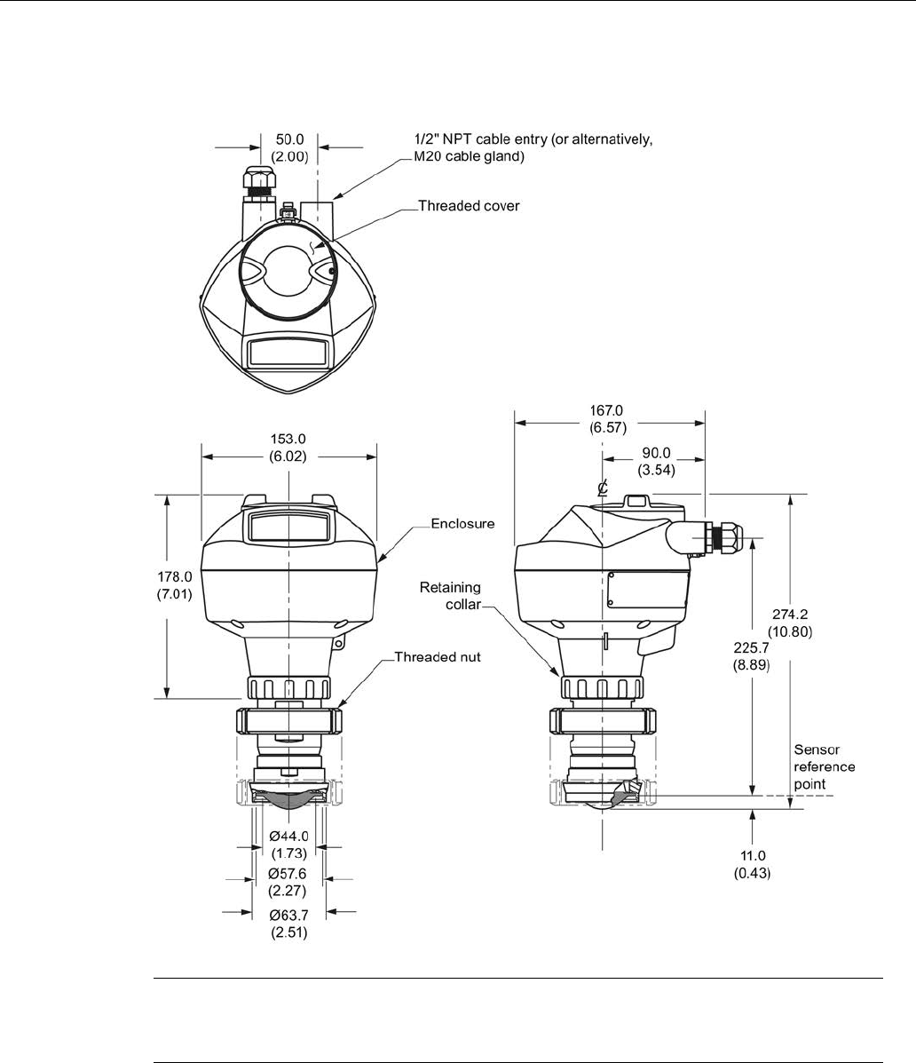
Dimension drawings
12.10 Hygienic encapsulated antenna (DN 50 nozzle/ slotted nut to DIN 11851)
SITRANS LR250 (FOUNDATION FIELDBUS)
Operating Instructions, 08/2014, A5E32221411-AC 237
12.10
Hygienic encapsulated antenna (DN 50 nozzle/ slotted nut to DIN
11851)
Dimensions in mm (inch)
Note
Cut out of process connection and placement of threaded nut are shown for illustration
purposes only.
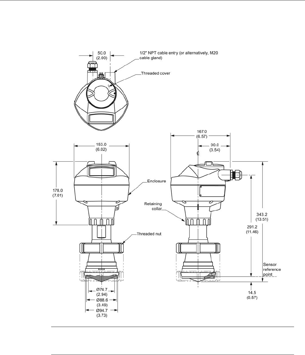
Dimension drawings
12.11 Hygienic encapsulated antenna (DN 80 nozzle/ slotted nut to DIN 11851)
SITRANS LR250 (FOUNDATION FIELDBUS)
238 Operating Instructions, 08/2014, A5E32221411-AC
12.11
Hygienic encapsulated antenna (DN 80 nozzle/ slotted nut to DIN
11851)
Dimensions in mm (inch)
Note
Cut out of process connection and placement of threaded nut are shown for illustration
purposes only.
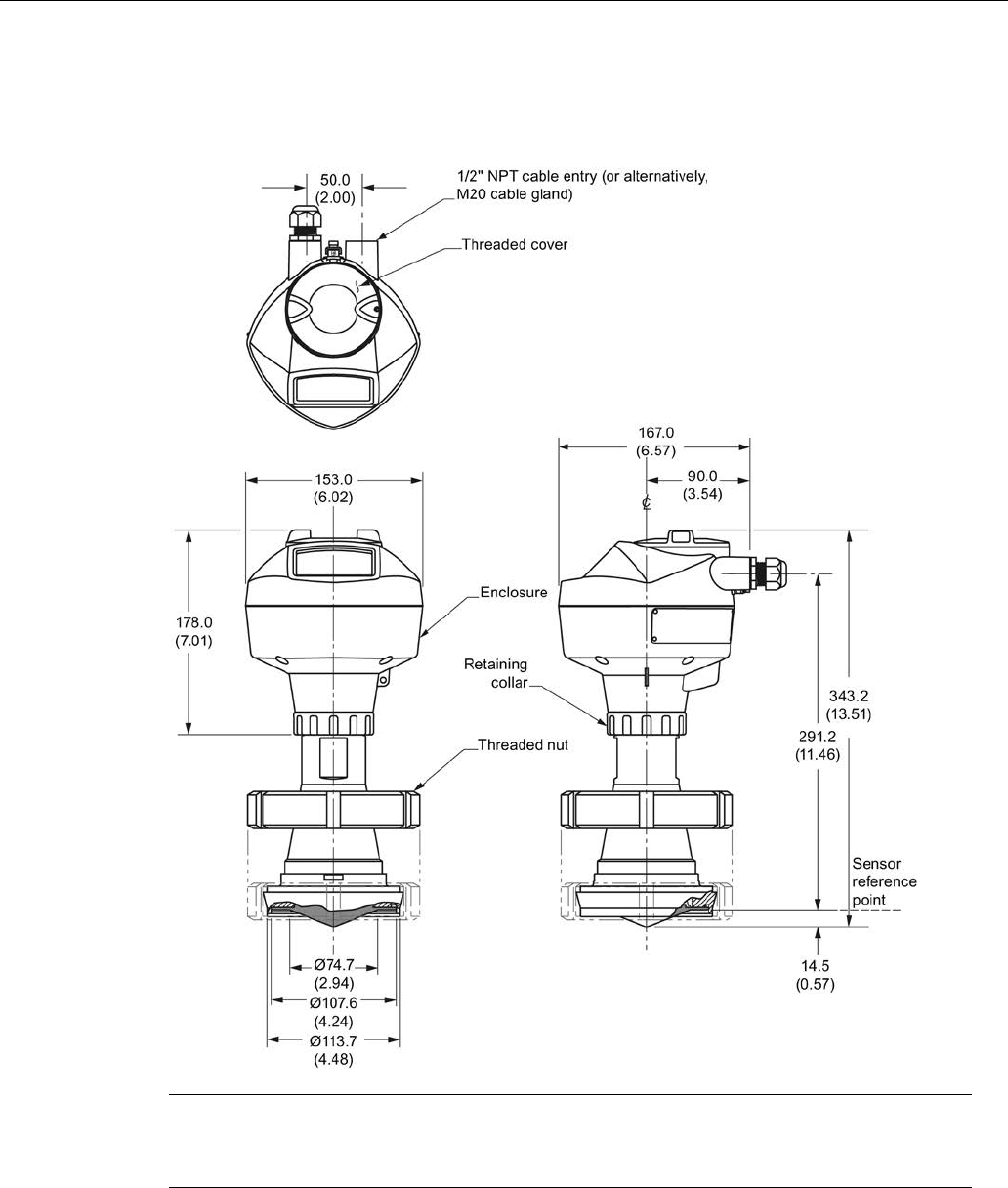
Dimension drawings
12.12 Hygienic encapsulated antenna (DN 100 nozzle/ slotted nut to DIN 11851)
SITRANS LR250 (FOUNDATION FIELDBUS)
Operating Instructions, 08/2014, A5E32221411-AC 239
12.12
Hygienic encapsulated antenna (DN 100 nozzle/ slotted nut to DIN
11851)
Dimensions in mm (inch)
Note
Cut out of process connection and placement of threaded nut are shown for illustration
purposes only.
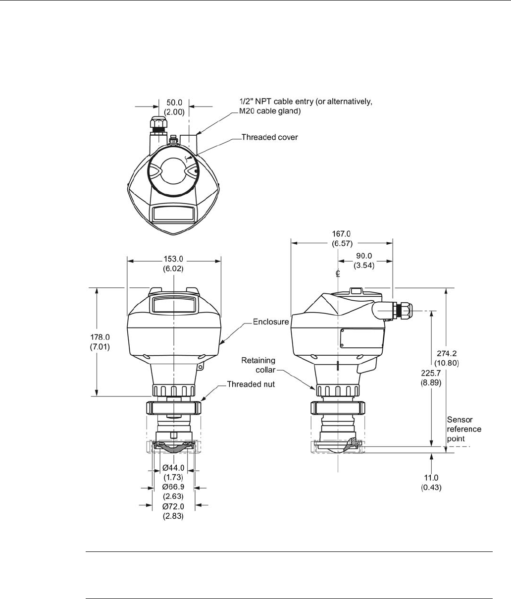
Dimension drawings
12.13 Hygienic encapsulated antenna (DN 50 aseptic slotted nut to DIN 11864-1)
SITRANS LR250 (FOUNDATION FIELDBUS)
240 Operating Instructions, 08/2014, A5E32221411-AC
12.13
Hygienic encapsulated antenna (DN 50 aseptic slotted nut to DIN
11864-1)
Dimensions in mm (inch)
Note
Cut out of process connection and placement of threaded nut are shown for illustration
purposes only.
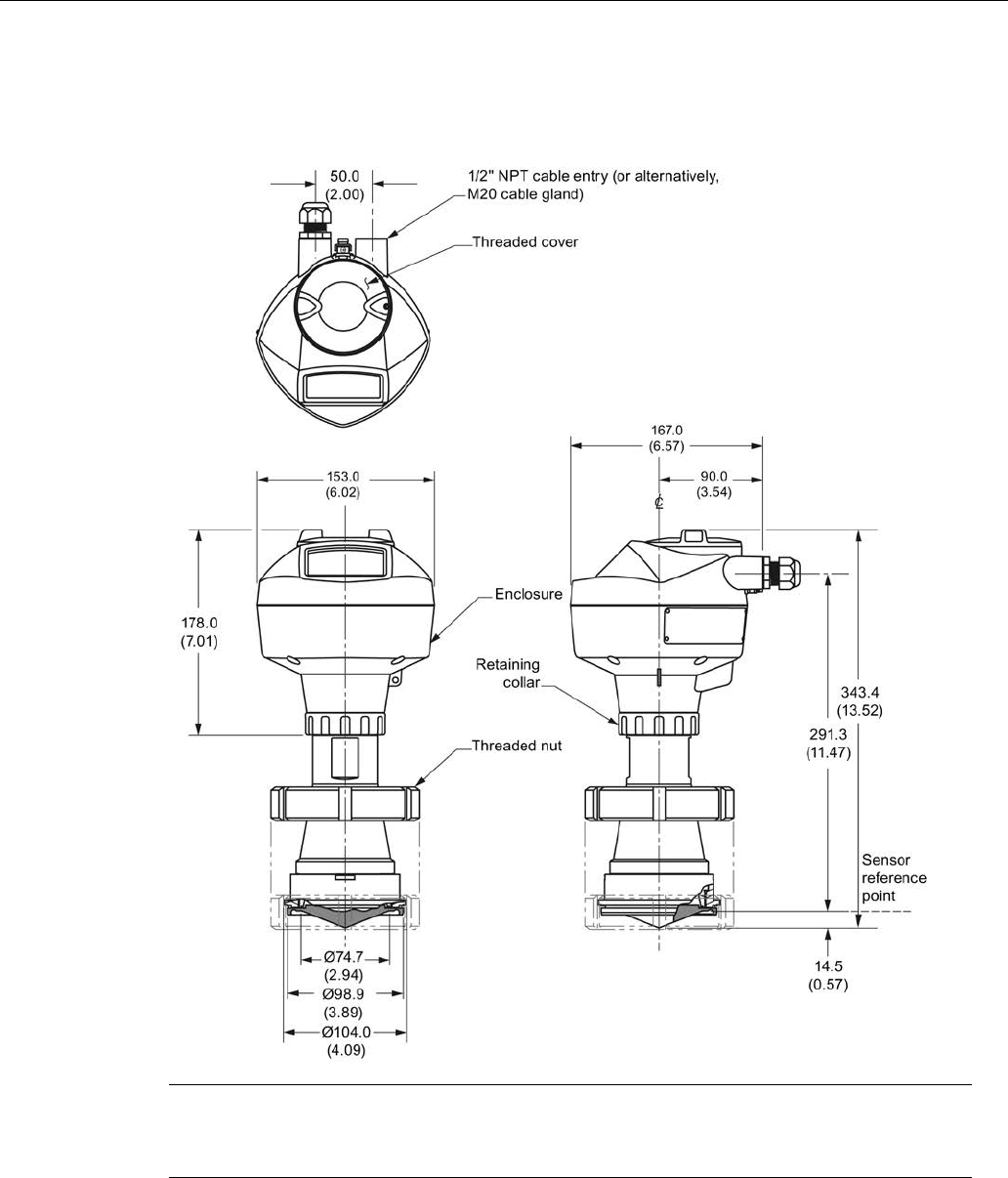
Dimension drawings
12.14 Hygienic encapsulated antenna (DN 80 aseptic slotted nut to DIN 11864-1)
SITRANS LR250 (FOUNDATION FIELDBUS)
Operating Instructions, 08/2014, A5E32221411-AC 241
12.14
Hygienic encapsulated antenna (DN 80 aseptic slotted nut to DIN
11864-1)
Dimensions in mm (inch)
Note
Cut out of process connection and placement of threaded nut are shown for illustration
purposes only.
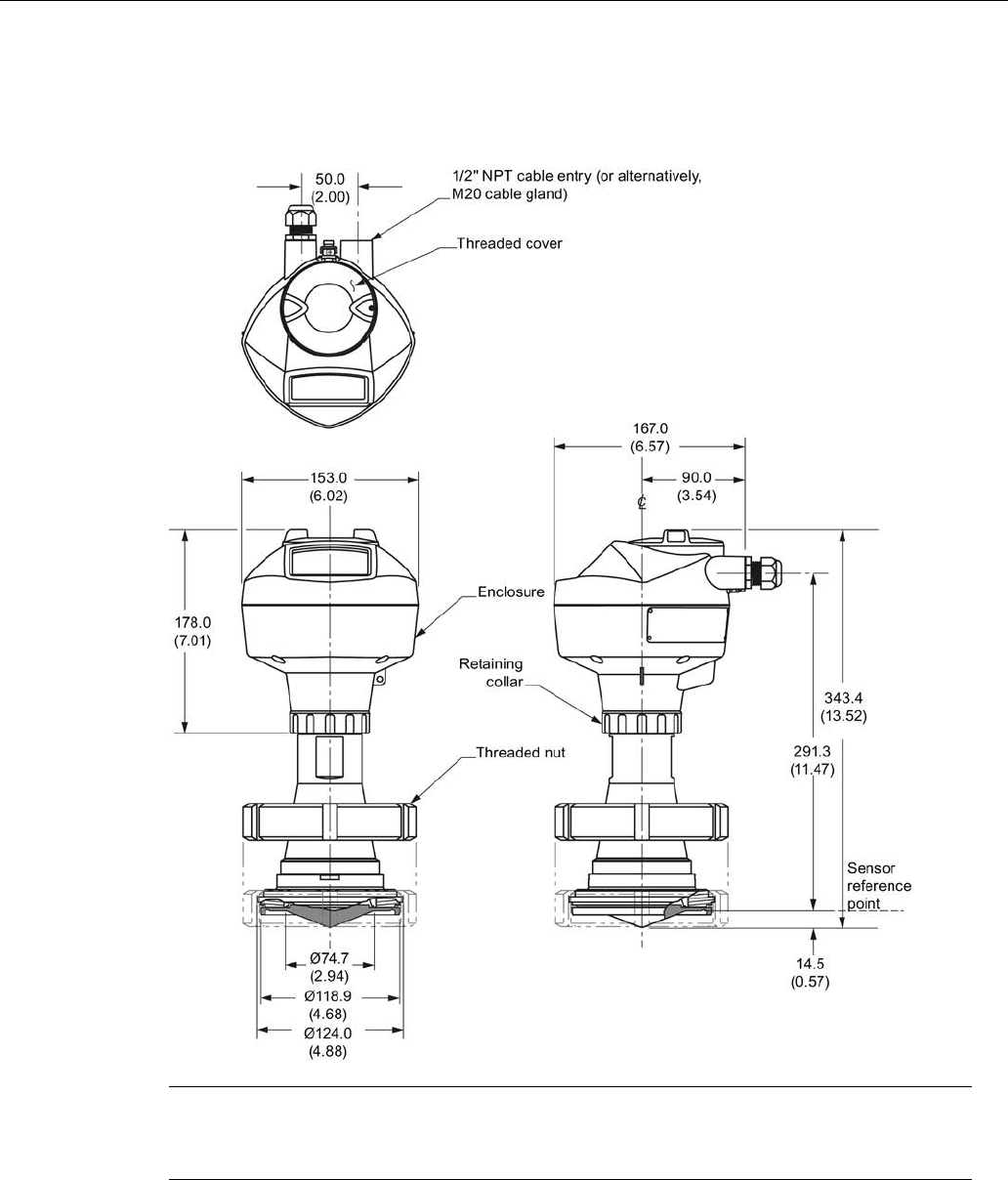
Dimension drawings
12.15 Hygienic encapsulated antenna (DN 100 aseptic slotted nut to DIN 11864-1)
SITRANS LR250 (FOUNDATION FIELDBUS)
242 Operating Instructions, 08/2014, A5E32221411-AC
12.15
Hygienic encapsulated antenna (DN 100 aseptic slotted nut to DIN
11864-1)
Dimensions in mm (inch)
Note
Cut out of process connection and placement of threaded nut are shown for illustration
purposes only.
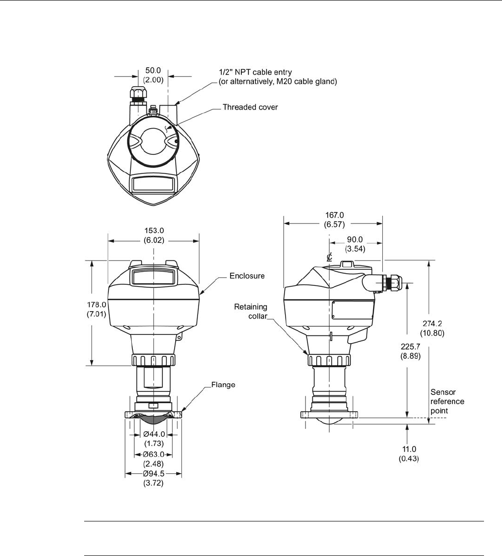
Dimension drawings
12.16 Hygienic encapsulated antenna (DN 50 aseptic flange to DIN 11864-2)
SITRANS LR250 (FOUNDATION FIELDBUS)
Operating Instructions, 08/2014, A5E32221411-AC 243
12.16
Hygienic encapsulated antenna (DN 50 aseptic flange to DIN 11864-2)
Dimensions in mm (inch)
Note
Cut out of process connection and flange are shown for illustration purposes only.
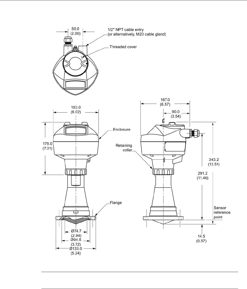
Dimension drawings
12.17 Hygienic encapsulated antenna (DN 80 aseptic flange to DIN 11864-2)
SITRANS LR250 (FOUNDATION FIELDBUS)
244 Operating Instructions, 08/2014, A5E32221411-AC
12.17
Hygienic encapsulated antenna (DN 80 aseptic flange to DIN 11864-2)
Dimensions in mm (inch)
Note
Cut out of process connection and flange are shown for illustration purposes only.
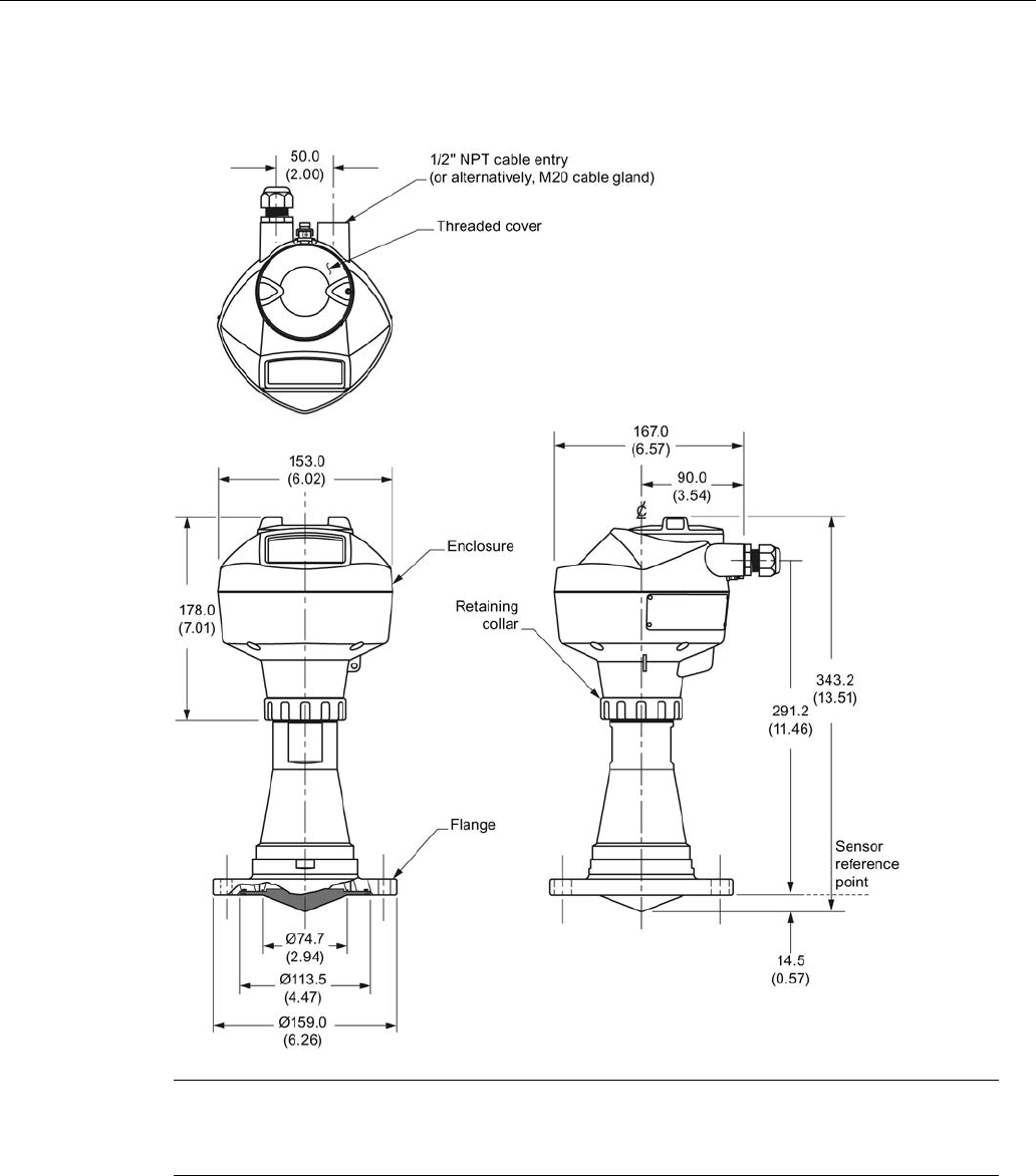
Dimension drawings
12.18 Hygienic encapsulated antenna (DN 100 aseptic flange to DIN 11864-2)
SITRANS LR250 (FOUNDATION FIELDBUS)
Operating Instructions, 08/2014, A5E32221411-AC 245
12.18
Hygienic encapsulated antenna (DN 100 aseptic flange to DIN 11864-
2)
Dimensions in mm (inch)
Note
The cut out of the process connection and the flange are shown for illustration purposes
only.
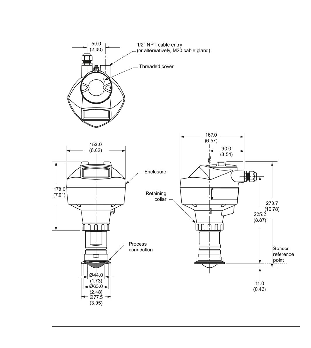
Dimension drawings
12.19 Hygienic encapsulated antenna (DN 50 aseptic clamp to DIN 11864-3)
SITRANS LR250 (FOUNDATION FIELDBUS)
246 Operating Instructions, 08/2014, A5E32221411-AC
12.19
Hygienic encapsulated antenna (DN 50 aseptic clamp to DIN 11864-3)
Dimensions in mm (inch)
Note
Cut out of process connection is shown for illustration purposes only.
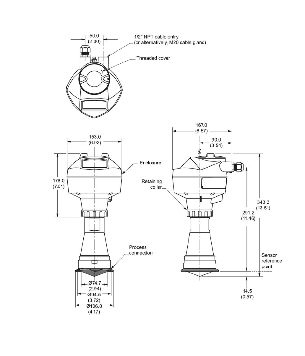
Dimension drawings
12.20 Hygienic encapsulated antenna (DN 80 aseptic clamp to DIN 11864-3)
SITRANS LR250 (FOUNDATION FIELDBUS)
Operating Instructions, 08/2014, A5E32221411-AC 247
12.20
Hygienic encapsulated antenna (DN 80 aseptic clamp to DIN 11864-3)
Dimensions in mm (inch)
Note
Cut out of process connection is shown for illustration purposes only.
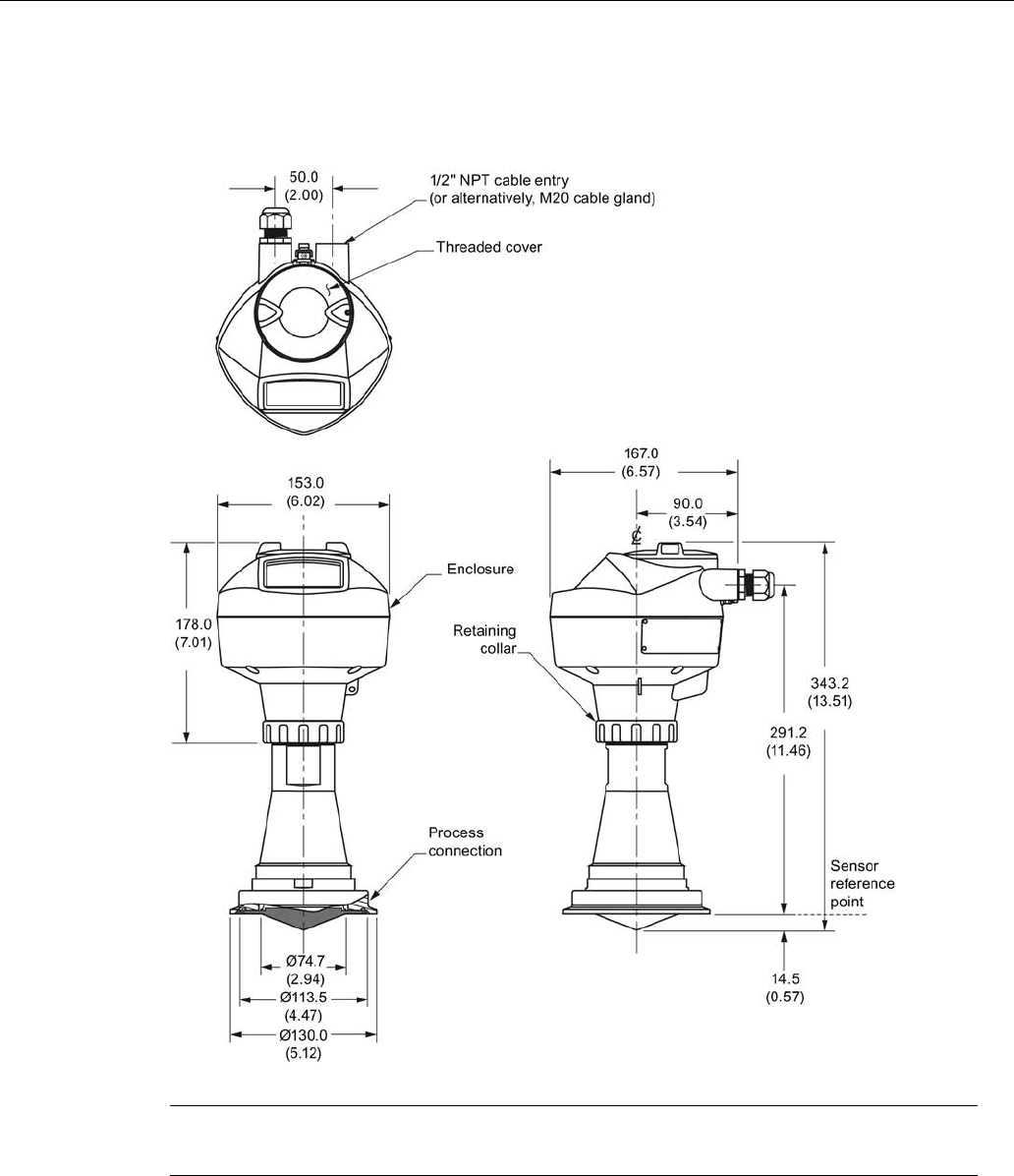
Dimension drawings
12.21 Hygienic encapsulated antenna (DN 100 aseptic clamp to DIN 11864-3)
SITRANS LR250 (FOUNDATION FIELDBUS)
248 Operating Instructions, 08/2014, A5E32221411-AC
12.21
Hygienic encapsulated antenna (DN 100 aseptic clamp to DIN 11864-
3)
Dimensions in mm (inch)
Note
Cut out of process connection is shown for illustration purposes only.
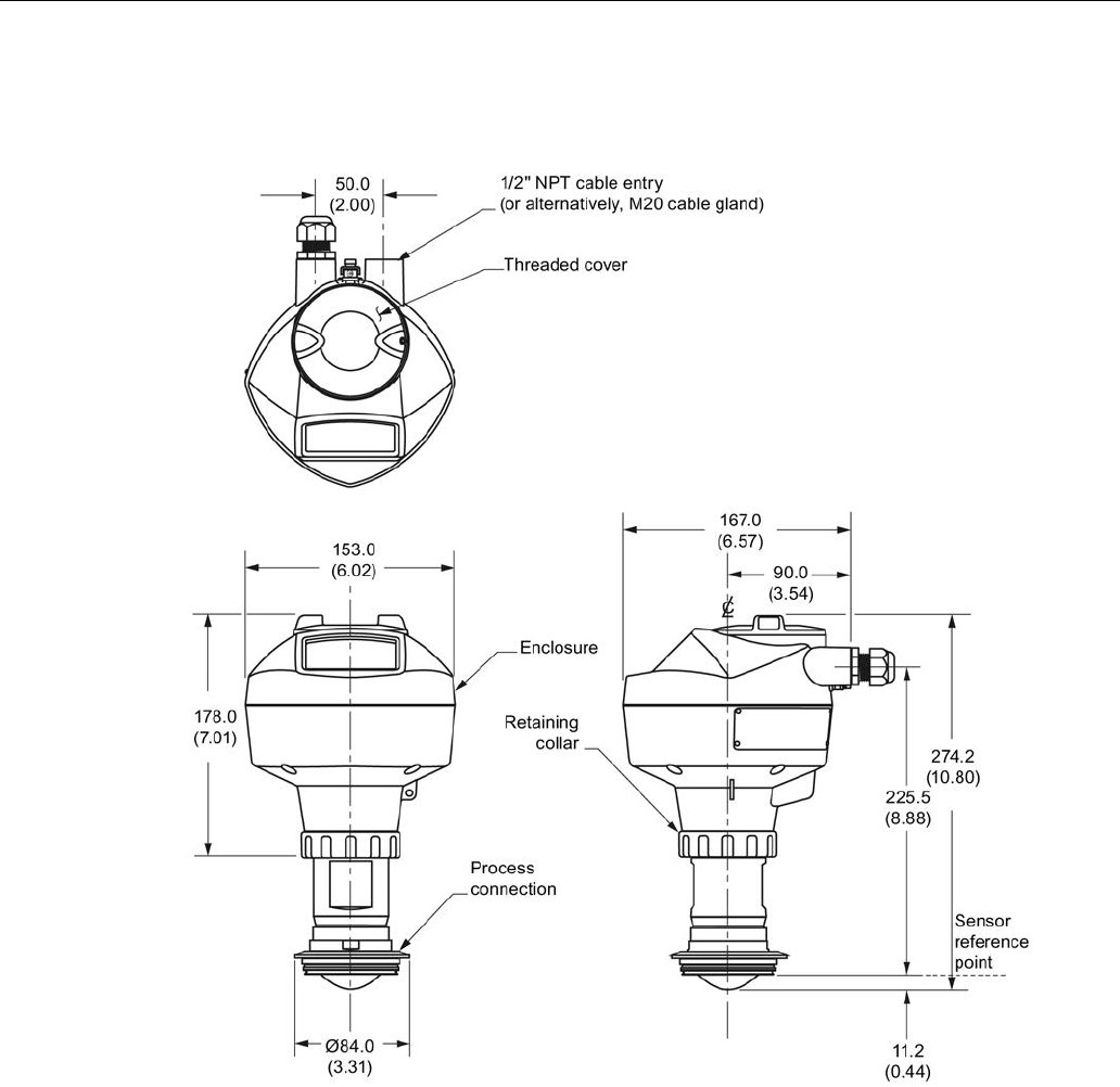
Dimension drawings
12.22 Hygienic encapsulated antenna (Tuchenhagen Type N)
SITRANS LR250 (FOUNDATION FIELDBUS)
Operating Instructions, 08/2014, A5E32221411-AC 249
12.22
Hygienic encapsulated antenna (Tuchenhagen Type N)
Dimensions in mm (inch)
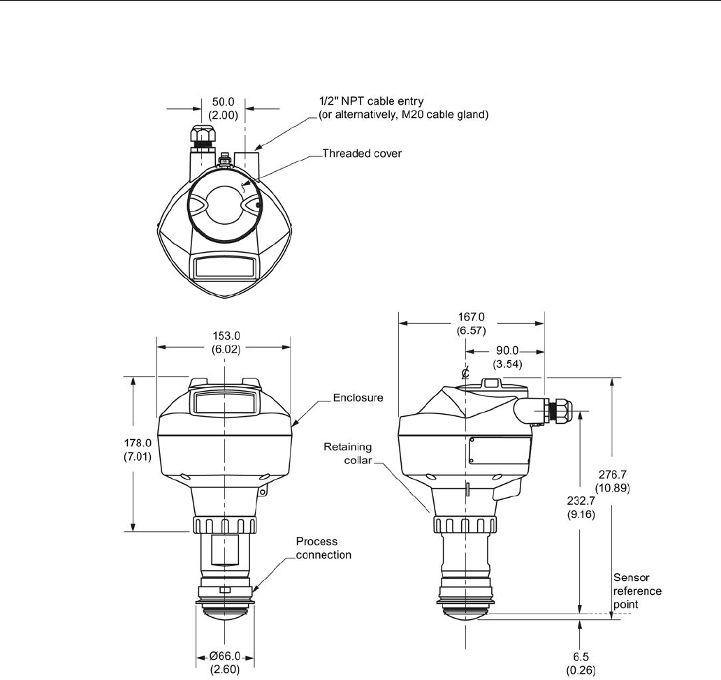
Dimension drawings
12.23 Hygienic encapsulated antenna (Tuchenhagen Type F)
SITRANS LR250 (FOUNDATION FIELDBUS)
250 Operating Instructions, 08/2014, A5E32221411-AC
12.23
Hygienic encapsulated antenna (Tuchenhagen Type F)
Dimensions in mm (inch)
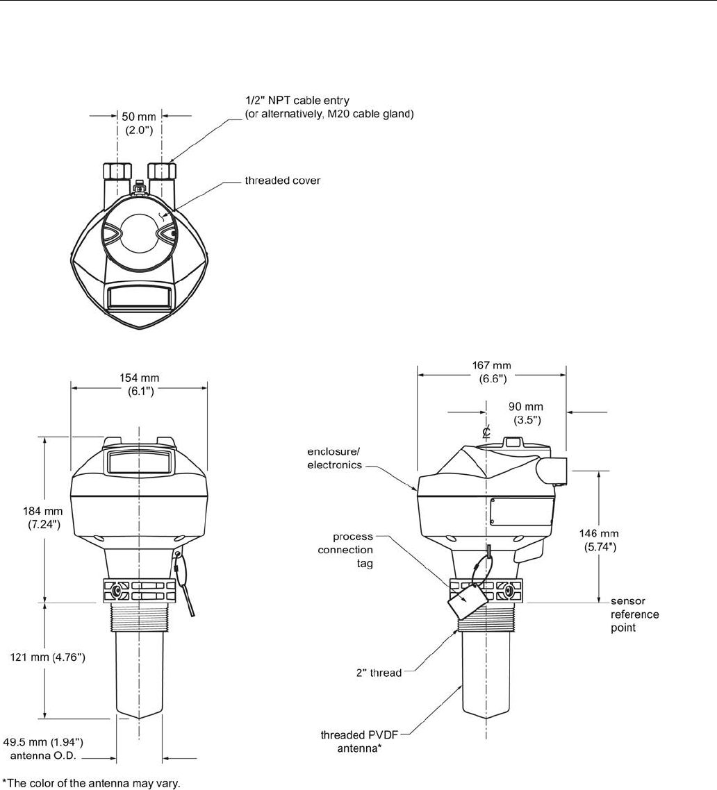
Dimension drawings
12.24 Threaded PVDF antenna
SITRANS LR250 (FOUNDATION FIELDBUS)
Operating Instructions, 08/2014, A5E32221411-AC 251
12.24
Threaded PVDF antenna

Dimension drawings
12.25 Threaded connection markings
SITRANS LR250 (FOUNDATION FIELDBUS)
252 Operating Instructions, 08/2014, A5E32221411-AC
Threaded PVDF antenna dimensions
Nominal antenna
size
Antenna O.D.
Height to sensor
reference point a)
Beam angle b)
Measurement
range
50 mm (2") 49.5 mm (1.94") 121 mm (4.76") 19 degrees 10 m (32.8 ft)c)
a) Height from bottom of antenna to sensor reference point as shown: see dimension drawing.
b) -3dB in the direction of the polarization axis. See Polarization reference point (Page 31) for an
illustration.
c) 20m when installed in stillpipe.
12.25
Threaded connection markings
With the exception of the threaded PVDF antenna, threaded connection markings are found on
the flat face/faces of the process connection.
Serial number: a unique number allotted to each process connection, including the date of
manufacture (MMDDYY) followed by a number from 001 to 999, (indicating the sequential unit
produced).
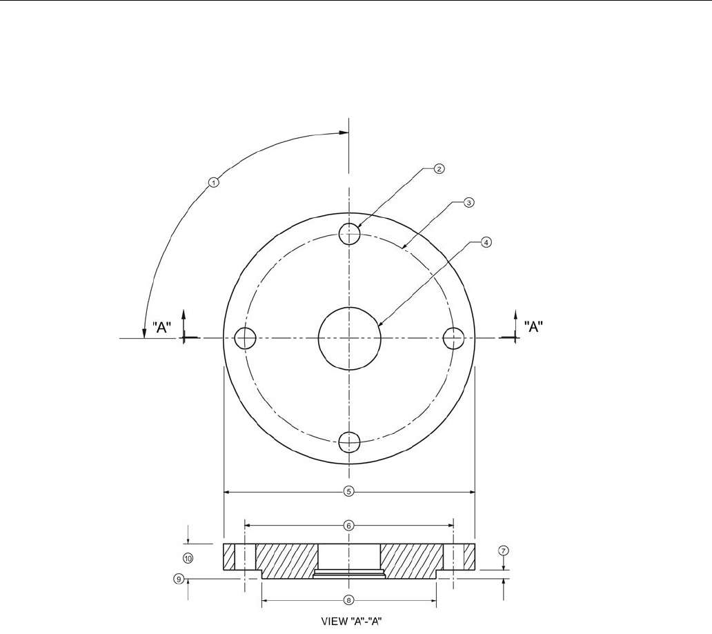
Dimension drawings
12.26 Raised-Face flange per EN 1092-1 for flanged horn antenna
SITRANS LR250 (FOUNDATION FIELDBUS)
Operating Instructions, 08/2014, A5E32221411-AC 253
12.26
Raised-Face flange per EN 1092-1 for flanged horn antenna
Stainless steel or optional alloy N06022/2.4602 (Hastelloy® C-22)
①
angle of adjacent bolt holes
⑥
bolt hole circle diameter
②
bolt hole diameter
⑦
facing height
③
bolt hole circle diameter
⑧
facing diameter
④
waveguide mounting hole
⑨
sensor reference point
⑤
Flange O.D.
⑩
thickness
Raised-Face flange dimensions

Dimension drawings
12.26 Raised-Face flange per EN 1092-1 for flanged horn antenna
SITRANS LR250 (FOUNDATION FIELDBUS)
254 Operating Instructions, 08/2014, A5E32221411-AC
Pipe size
Flange bolt
hole pattern
⑤
Flange
O.D.
(mm)
③
Bolt hole
circle Ø
(mm)
②
Bolt hole Ø
(mm)
No. of bolts
①
Angle of
adjacent
bolt holes
⑧
Facing Ø
(mm)
⑩
Thickness
(mm)
DN50 PN10/PN16 165 125 18 4 90 102 18
DN80 PN10/PN16 200 160 18 8 45 138 20
DN100 PN10/PN16 220 180 18 8 45 158 20
DN150 PN10/PN16 285 240 22 8 45 212 22
DN50 PN25/PN40 165 160 18 4 90 138 20
DN80 PN25/PN40 200 160 18 8 45 138 24
DN100 PN25/PN40 235 190 22 8 45 162 24
DN150 PN25/PN40 300 250 26 8 45 218 28
Raised-Face flange markings
Blind Flange Markings (Optional
Manufacturer’s Logo [optional]; Flange
Standard; Nominal Size; Material; Heat
Code)
Machining Identification
Welded Assembly Identification a)
Serial no.
Logo
Flange series
Flange
series
Heat Code
no.
Facing
Manufacturer’s logo; EN 1092-1 05 ‘B1’;
‘DN50’ ‘PN16’ ‘1.4404 or 1.4435’
A1B2C3
mmddyyx
xx xxxxx xxxxx A1B2C3 RF
a) When flange material is alloy N06022/2.4602, additional material and heat code identification
is provided.
The flange markings are located around the outside edge of the flange.
Serial number: a unique number allotted to each flange, including the date of manufacture
(MMDDYY) followed by a number from 001 to 999 (indicating the sequential
unit produced).
Flange series:
the Siemens Milltronics drawing identification.
Heat code: a flange material batch code identification.
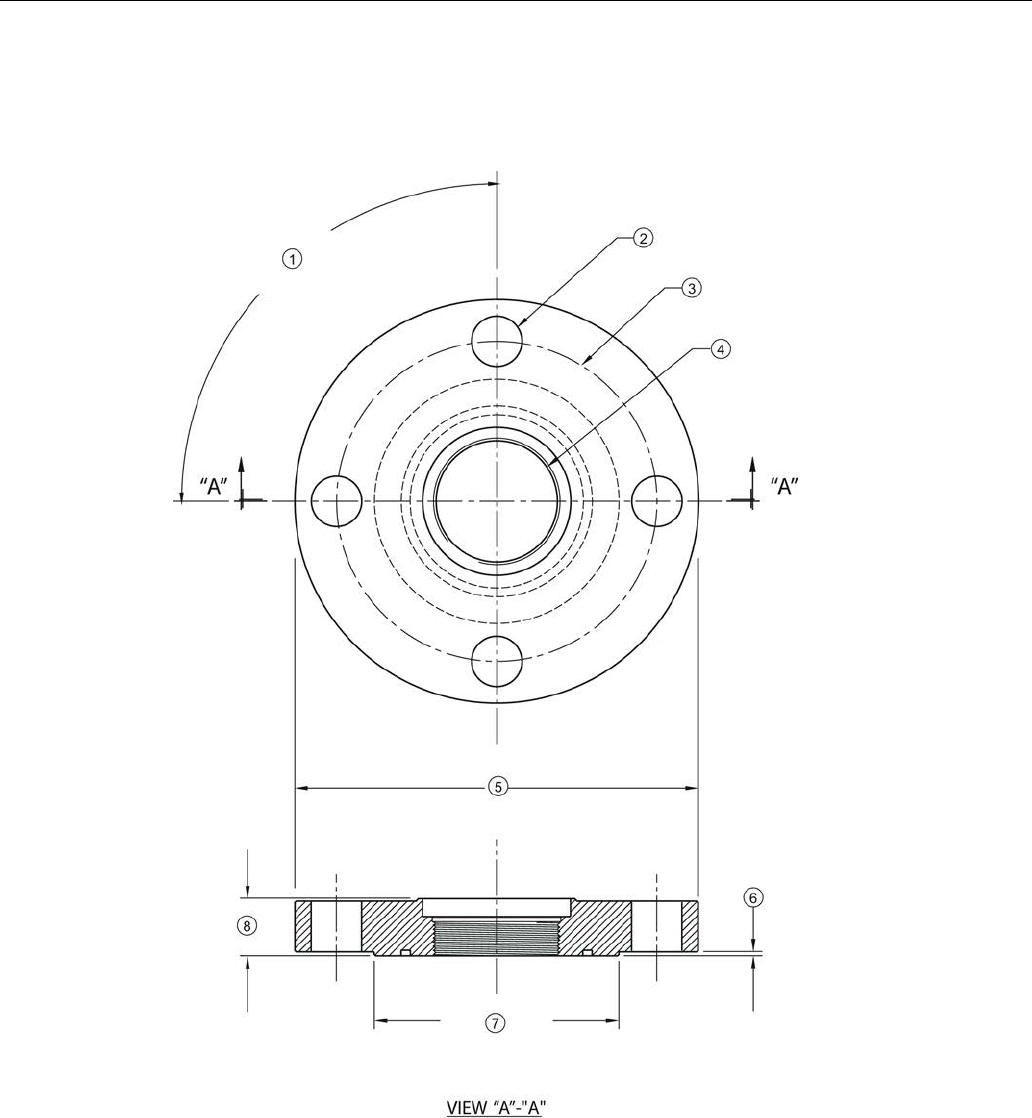
Dimension drawings
12.27 Raised-Face flange per EN 1092-1 for flanged encapsulated antenna
SITRANS LR250 (FOUNDATION FIELDBUS)
Operating Instructions, 08/2014, A5E32221411-AC 255
12.27
Raised-Face flange per EN 1092-1 for flanged encapsulated antenna
Stainless steel
①
angle of adjacent bolt holes
⑤
flange O.D.
②
bolt hole diameter
⑥
facing height
③
bolt hole circle diameter
⑦
facing diameter
④
antenna
⑧
flange thickness

Dimension drawings
12.27 Raised-Face flange per EN 1092-1 for flanged encapsulated antenna
SITRANS LR250 (FOUNDATION FIELDBUS)
256 Operating Instructions, 08/2014, A5E32221411-AC
Raised-Face flange dimensions
Pipe size
Flange class
⑤
Flange
O.D.
[mm
(inch)]
③
Bolt hole
circle Ø
[mm
(inch)]
②
Bolt hole
Ø [mm
(inch)]
No. of bolt
holes
①
Angle of
adjacent
bolt holes
⑦
Facing Ø
[mm
(inch)]
⑨
Flange
thickness
[mm
(inch)]
⑥
Flange
facing
thickness
[mm
(inch)]
2" 150 LB 152
(5.98)
120.7
(4.75)
19 (0.75) 4 90 92.1
(3.63)
20.6
(0.81)
1.5 (0.06)
3" 190
(7.48)
152.4
(6.00)
127 (5.00) 25.9
(1.02)
2 (0.08)
4" 230
(9.06)
190.5
(7.50)
8 45 157.2
(6.19)
2 (0.08)
6" 280
(11.02)
241.3
(9.50)
22.2
(0.87)
215.9
(8.50)
26.9
(1.06)
1.5 (0.06)
DN50 PN10/16 155
(6.10)
125 (4.92) 18 (0.71) 4 90 102 (4.02) 18 (0.71) 2 (0.08)
DN80 200
(7.87)
160 (6.30) 8 45 138 (5.43) 20 (0.79)
2 (0.08)
DN100 220
(8.66)
180 (7.09) 158 (6.22) 2 (0.08)
DN150 285
(11.22)
240 (9.45) 22 (0.87) 212 (8.35) 22 (0.87) 2 (0.08)
50A 10K 155
(6.10)
120 (4.72) 19 (0.75) 4 90 96 (3.78) 16 (0.63) 2 (0.08)
80A 185
(7.28)
150 (5.91) 8 45 126 (4.96) 18 (0.71)
2 (0.08)
100A 210
(8.27)
175 (6.89) 151 (5.94) 2 (0.08)
150A 280
(11.02)
240 (9.45) 23 (0.91) 212 (8.35) 22 (0.87) 2 (0.08)

Dimension drawings
12.27 Raised-Face flange per EN 1092-1 for flanged encapsulated antenna
SITRANS LR250 (FOUNDATION FIELDBUS)
Operating Instructions, 08/2014, A5E32221411-AC 257
Raised-Face flange markings
Blind Flange Markings (Optional
Manufacturer’s Logo [optional]; Flange
Standard; Nominal Size; Material; Heat
Code)
Machining Identification
Welded Assembly Identification
Serial no.
Logo
Flange series
Flange
series
Heat Code
no.
Facing
Manufacturer’s logo; EN 1092-1 05 ‘B1’;
‘DN50’ ‘PN16’ ‘1.4404 or 1.4435’
A1B2C3
mmddyyx
xx xxxxx xxxxx A1B2C3 RF
The flange markings are located around the outside edge of the flange.
Serial number: a unique number allotted to each flange, including the date of manufacture
(MMDDYY) followed by a number from 001 to 999 (indicating the sequential
unit produced).
Flange series: the Siemens Milltronics drawing identification.
Heat code: a flange material batch code identification.
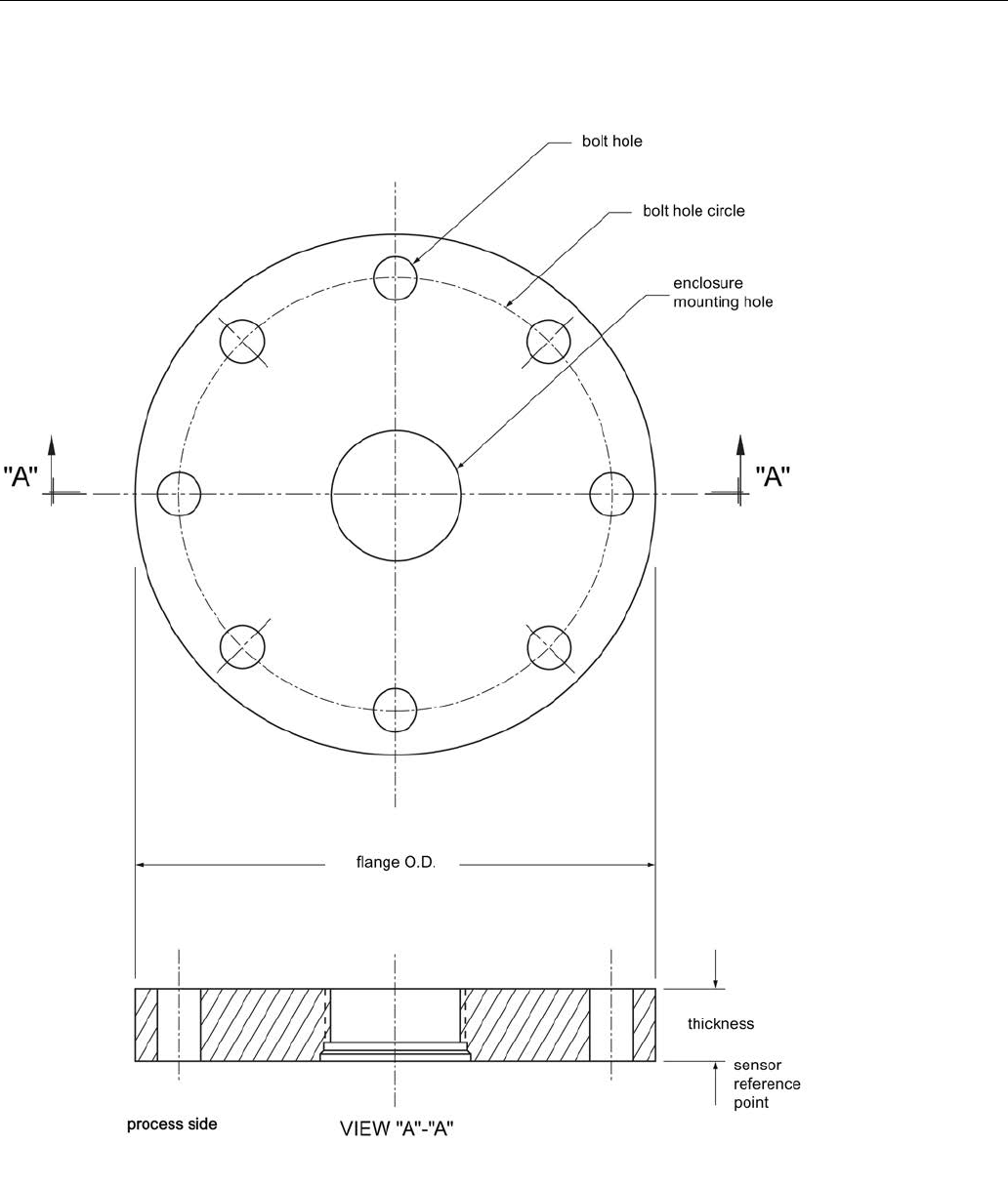
Dimension drawings
12.28 Flat-Face flange
SITRANS LR250 (FOUNDATION FIELDBUS)
258 Operating Instructions, 08/2014, A5E32221411-AC
12.28
Flat-Face flange

Dimension drawings
12.28 Flat-Face flange
SITRANS LR250 (FOUNDATION FIELDBUS)
Operating Instructions, 08/2014, A5E32221411-AC 259
Flat-Face flange dimensions
Flange size a)
Flange class
Flange O.D.
Bolt hole circle
Ø
Bolt hole Ø
No. of bolt
holes
Thickness
2" ASME 150 lb 6.0" 4.75" 0.75" 4 0.88"
3" ASME 150 lb 7.5" 6.0" 0.75" 4 0.96"
4" ASME 150 lb 9.0" 7.50" 0.75" 8 1.25"
2" ASME 300 lb 6.50" 5.00" 0.75" 8 1.12"
3" ASME 300 lb 8.25" 6.62" 0.88" 8 1.38"
4" ASME 300 lb 10.00" 7.88" 0.88" 8 1.50"
DN50 EN PN16 165 mm 125 mm 18 mm 4 24.4 mm
DN80 EN PN16 200 mm 160 mm 18 mm 8 31.8 mm
DN100 EN PN16 220 mm 180 mm 18 mm 8 31.8 mm
DN50 EN PN40 165 mm 125 mm 18 mm 4 25.4 mm
DN80 EN PN40 200 mm 160 mm 18 mm 8 31.8 mm
DN100 EN PN40 235 mm 190 mm 22 mm 8 38.1 mm
50A JIS 10K 155 mm 120 mm 19 mm 4 23.8 mm
80A JIS 10K 185 mm 150 mm 19 mm 8 24.4 mm
100A JIS 10K 210 mm 175 mm 19 mm 8 28.5 mm
a) A 2" flange is designed to fit a 2" pipe: for actual flange dimensions see Flange O.D. Flange
markings located around the outside edge of the flat faced flange identify the flange assembly on
which the device is mounted.
Flat-Face flange markings
Flat Face Flange Identification
Welded Assembly
Identification
Serial No. Logo Flange series Material Heat
code
Flange
series
Heat code
no.
Series Nominal size
MMDDYYXXX 25556 2 150 316L/ 1.4404 or
316L/ 1.4435
A1B2C3 25546 A1B2C3
DN80 PN16
Serial number:
A unique number allotted to each flange, including the date of manufacture
(MMDDYY) followed by a number from 001 to 999 (indicating the sequential
unit produced).
Flange series:
The Siemens Milltronics drawing identification.

Dimension drawings
12.28 Flat-Face flange
SITRANS LR250 (FOUNDATION FIELDBUS)
260 Operating Instructions, 08/2014, A5E32221411-AC
Nominal size:
The flange size followed by the hole pattern for a particular flange class. For
example:
• A 2 inch ASME B16.5 150 lb class flange (North America)
• A DN80 EN 1092-1 PN16 class flange (Europe)
Material:
The basic flange material (AISI or EU material designation). North American
material codes are followed by European ones. For example, material
designation 316L/1.4404.
Heat code:
A flange material batch code identification.
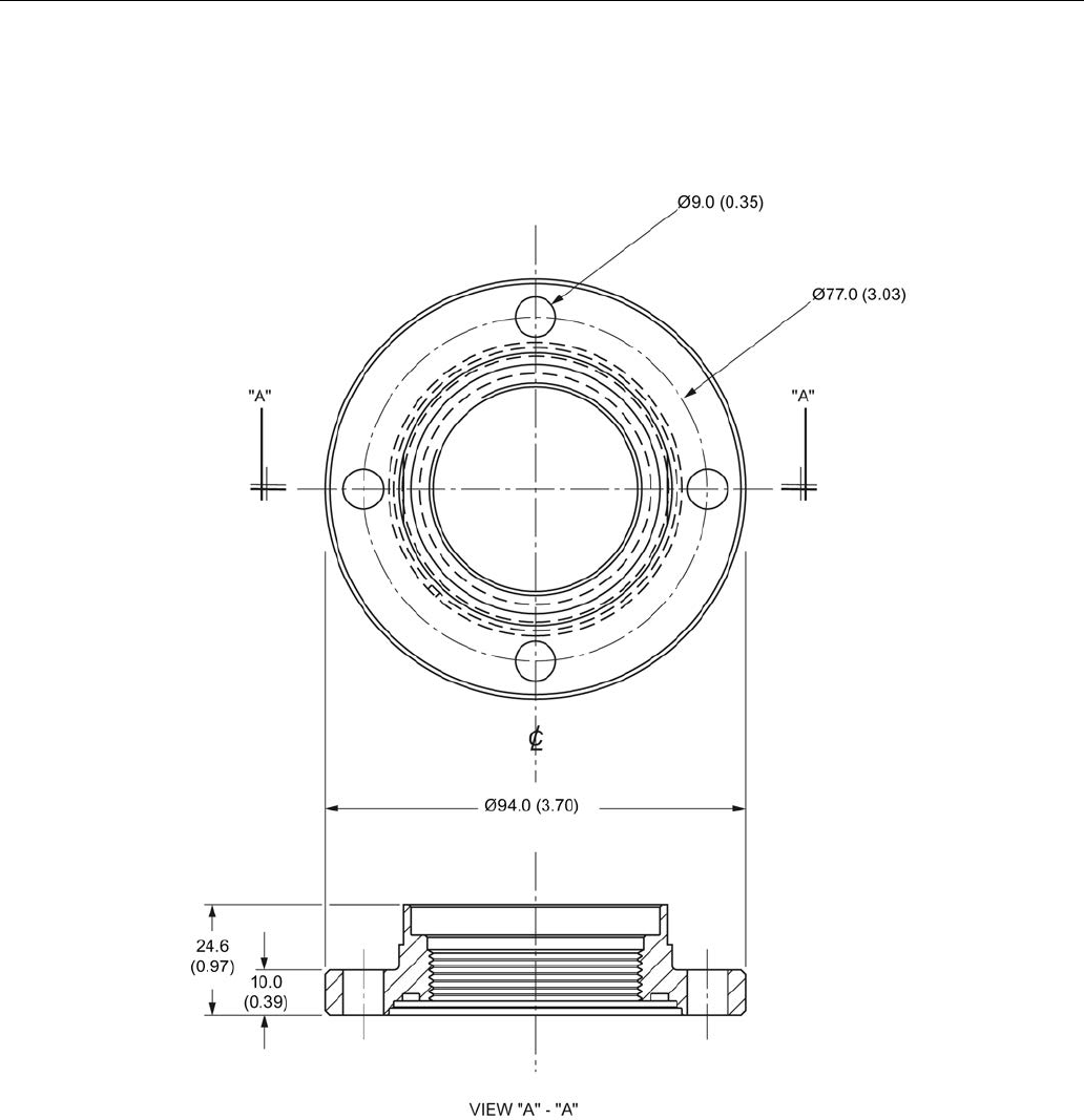
Dimension drawings
12.29 Aseptic/hygienic flange DN50, DN80, DN100 for DIN 11864-2
SITRANS LR250 (FOUNDATION FIELDBUS)
Operating Instructions, 08/2014, A5E32221411-AC 261
12.29
Aseptic/hygienic flange DN50, DN80, DN100 for DIN 11864-2
Aseptic/hygienic flange DN50
Dimensions in mm (inch)
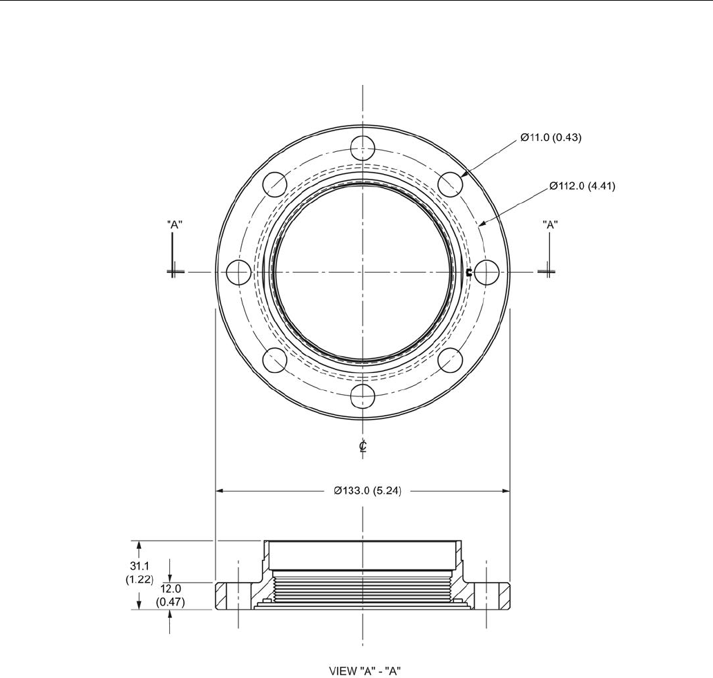
Dimension drawings
12.29 Aseptic/hygienic flange DN50, DN80, DN100 for DIN 11864-2
SITRANS LR250 (FOUNDATION FIELDBUS)
262 Operating Instructions, 08/2014, A5E32221411-AC
Aseptic/hygienic flange DN80
Dimensions in mm (inch)
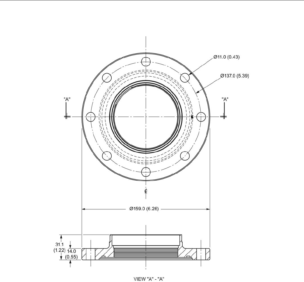
Dimension drawings
12.29 Aseptic/hygienic flange DN50, DN80, DN100 for DIN 11864-2
SITRANS LR250 (FOUNDATION FIELDBUS)
Operating Instructions, 08/2014, A5E32221411-AC 263
Aseptic/hygienic flange DN100
Dimensions in mm (inch)

Dimension drawings
12.30 Process connection tag (pressure rated versions)
SITRANS LR250 (FOUNDATION FIELDBUS)
264 Operating Instructions, 08/2014, A5E32221411-AC
12.30
Process connection tag (pressure rated versions)
For pressure-rated versions only, the process connection label lists the following information:
Process connection tag (pressure rated versions)
Item
Sample Text
Comments/Explanation
SERIAL #
GYZ / 00000000 Pressure Boundary Assembly
NOMINAL PIPE SIZE (DN)
4 INCH / 100mm Nominal Pipe Size
INSTRUMENT MAWP (PS)
11.0
BAR
Maximum Allowable Working Pressure at
Design Temperature for the device
DESIGN TEMP. (TS)
200
ºC
Maximum Allowable Working Temperature
MINIMUM PROCESS
15.9
BAR
AT
40
ºC
Minimum Wetted Process Conditions
TEST PRESSURE (PT)
22.7
BAR
Production Test Pressure
TEST DATE
10/11/11 Date of Pressure Test (Year/Month/Day)
CONNECTION SERIES
ASME B16.5 Flange Series: dimensional pattern based on
ASME B16.5 flange standards
PROCESS SERIES
25546 Pressure Tag Family Series
WETTED NON-METALLICS
TFM Antenna Emitter
WETTED METALLICS
316L Process Connection Material(s)
WETTED SEALS
FKM Seal Material(s)
● Minimum Wetted Process Conditions: the minimum pressure and temperature to which the
device assembly may be exposed in the process, and continue to provide a pressure-
retaining function.
● Pressure Tag Family Series: the identification number used to indicate specific process
connection information relating to operating conditions.
● For Flanged encapsulated antenna: this information is laser-etched on antenna body
BACK FACE
Sample Text
Comments/Explanation
CRN 0Fxxxxx.5 Canadian Registration Number (CRN)

SITRANS LR250 (FOUNDATION FIELDBUS)
Operating Instructions, 08/2014, A5E32221411-AC 265
Appendix A: Technical reference
A
Note
Where a number follows the parameter name [for example,
Master Reset (4.1.)
] this is the
parameter access number via the handheld programmer. See Parameter Reference
(Page 143) for a complete list of parameters.
A.1
Principles of operation
SITRANS LR250 is a 2-wire 25 GHz pulse radar level transmitter for continuous monitoring of
liquids and slurries. (The microwave output level is significantly less than that emitted from
cellular phones.) Radar level measurement uses the time of flight principle to determine distance
to a material surface. The device transmits a signal and waits for the return echo. The transit
time is directly proportional to the distance from the material.
Pulse radar uses polarized electromagnetic waves. Microwave pulses are emitted from the
antenna at a fixed repetition rate, and reflect off the interface between two materials with
different dielectric constants (the atmosphere and the material being monitored).
Electromagnetic wave propagation is virtually unaffected by temperature or pressure changes,
or by changes in the vapor levels inside a vessel. Electromagnetic waves are not attenuated by
dust.
SITRANS LR250 consists of an enclosed electronic circuit coupled to an antenna and process
connection. The electronic circuit generates a radar signal (25 GHz) that is directed to the
antenna.
The signal is emitted from the antenna, and the reflected echoes are digitally converted to an
echo profile. The profile is analyzed to determine the distance from the material surface to the
sensor reference point. See Dimension drawings (Page 221). This distance is used as a basis
for the display of material level and mA output.

Appendix A: Technical reference
A.2 Echo processing
SITRANS LR250 (FOUNDATION FIELDBUS)
266 Operating Instructions, 08/2014, A5E32221411-AC
A.2
Echo processing
A.2.1
Process Intelligence
The signal processing technology embedded in Siemens radar level devices is known as
Process Intelligence
.
Process intelligence provides high measurement reliability regardless of the dynamically
changing conditions within the vessel being monitored. The embedded Process Intelligence
dynamically adjusts to the constantly changing material surfaces within these vessels.
Process Intelligence is able to differentiate between the true microwave reflections from the
surface of the material and unwanted reflections being returned from obstructions such as seam
welds or supports within a vessel. The result is repeatable, fast and reliable measurement. This
technology was developed as result of field data gained over some twenty years from more than
1,000,000 installations in many industries around the world.
Higher order mathematical techniques and algorithms are used to provide intelligent processing
of microwave reflection profiles. This "knowledge based" technique produces superior
performance and reliability.
A.2.2
Echo Selection
Time Varying Threshold (TVT)
A Time Varying Threshold (TVT) hovers above the echo profile to screen out unwanted
reflections (false echoes).
In most cases the material echo is the only one which rises above the default TVT.
In a vessel with obstructions, a false echo may occur. See Auto False Echo Suppression
(Page 271) for more details.
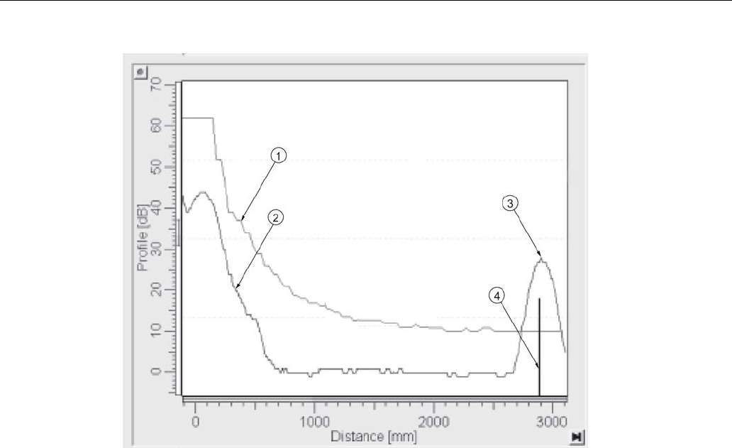
Appendix A: Technical reference
A.2 Echo processing
SITRANS LR250 (FOUNDATION FIELDBUS)
Operating Instructions, 08/2014, A5E32221411-AC 267
①
default TVT
②
echo profile
③
material level
④
echo marker
The device characterizes all echoes that rise above the TVT as potential good echoes. Each
peak is assigned a rating based on its strength, area, height above the TVT, and reliability,
amongst other characteristics.
Algorithm (2.5.7.1.)
The true echo is selected based on the setting for the Echo selection algorithm. Options are
t
rue
F
irst Echo,
L
argest Echo, or
b
est of
F
irst and
L
argest.
Position Detect (2.5.7.2.)
The echo position detection algorithm determines which point on the echo will be used to
calculate the precise time of flight, and calculates the range using the calibrated propagation
velocity [see
Propagation Factor (2.5.3.)
for values]. There are three options:
●
Center
●
Hybrid
(Center and CLEF)
●
CLEF
(Constrained Leading Edge Fit)
Center
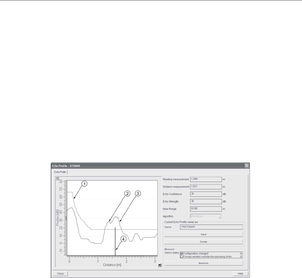
Appendix A: Technical reference
A.2 Echo processing
SITRANS LR250 (FOUNDATION FIELDBUS)
268 Operating Instructions, 08/2014, A5E32221411-AC
Uses center of the echo.
Hybrid
Uses the Center algorithm for the top part of the vessel, and the CLEF algorithm for the part
nearest the vessel bottom, according to the setting for
CLEF range
.
CLEF (Constrained Leading Edge Fit)
● Uses the leading edge of the echo.
● Is used mainly to process the echo from materials with a low dK value.
In an almost empty flat-bottomed vessel, a low dK material may reflect an echo weaker than the
echo from the vessel bottom. The echo profile shows these echoes merging. The device may
then report a material level equal to or lower than empty.
The CLEF algorithm enables the device to report the level correctly.
Example: CLEF off: Position set to Hybrid
Vessel height: 1.5 m; CLEF range set to 0 (Center algorithm gives the same result.)
①
default TVT
②
material echo
③
vessel bottom echo selected
④
echo marker
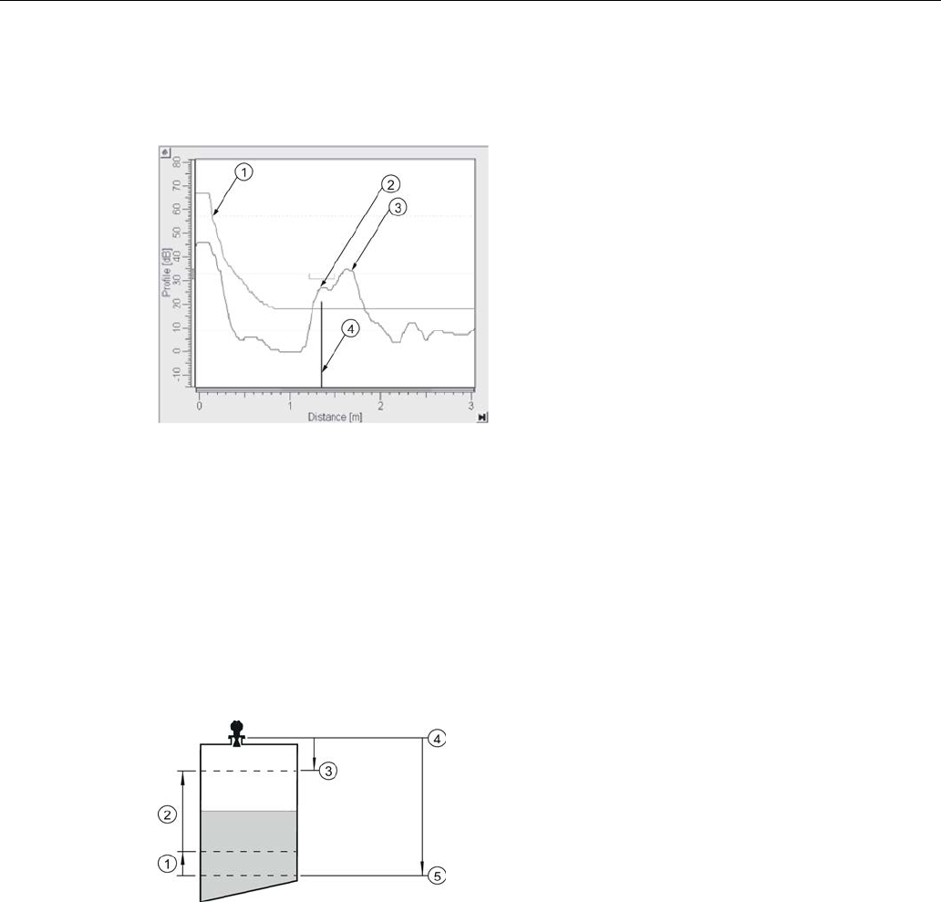
Appendix A: Technical reference
A.2 Echo processing
SITRANS LR250 (FOUNDATION FIELDBUS)
Operating Instructions, 08/2014, A5E32221411-AC 269
Example: CLEF enabled
Vessel height: 1.5 m; CLEF range set to 0.5 m
①
default TVT
②
material echo selected
③
vessel bottom echo
④
echo marker
A.2.3
CLEF Range
CLEF Range (2.5.7.4.)
is referenced from Low Calibration Point (process empty level). When the
Hybrid
algorithm is selected in
Position Detect (2.5.7.2.)
, the CLEF algorithm will be applied up
to the limit of CLEF Range. Above this limit the Center algorithm will be applied.
①
CLEF Range
②
(Center algorithm applied)
③
High Calibration Point (process full level)
④
Sensor reference point
⑤
Low Calibration Point (process empty level)

Appendix A: Technical reference
A.2 Echo processing
SITRANS LR250 (FOUNDATION FIELDBUS)
270 Operating Instructions, 08/2014, A5E32221411-AC
A.2.4
Measurement Response
Note
Units are defined in
Units (2.3.1.)
and are in meters by default.
Response Rate (2.3.8.1.)
limits the maximum rate at which the display and output respond to
changes in the measurement. There are three preset options: slow, medium, and fast.
Once the real process fill/empty rate (m/s by default) is established, a response rate can be
selected that is slightly higher than the application rate. Response Rate automatically adjusts the
filters that affect the output response rate.
Note
Changing Response Rate resets
Fill Rate per Minute (2.3.8.2.)
,
Empty Rate per Minute
(2.3.8.3.)
, and
Shots (2.5.6.)
.
Response Rate
(2.3.8.1)
Fill Rate (2.3.8.2)/Empty Rate (2.3.8.3)
*
Slow
0.1 m/min (0.32 ft/min) 25
Medium
1.0 m/min (3.28 ft.min) 10
Fast
10.0 m/min (32.8 ft/min) 5
A.2.5
Echo Threshold
Confidence (2.5.9.1.)
describes the quality of an echo. Higher values represent higher quality.
Echo Threshold (2.5.7.3.)
defines the minimum confidence value required for an echo to be
accepted as valid and evaluated.

Appendix A: Technical reference
A.2 Echo processing
SITRANS LR250 (FOUNDATION FIELDBUS)
Operating Instructions, 08/2014, A5E32221411-AC 271
A.2.6
Echo Lock
If the echo selected by
Algorithm
is within the Echo Lock window, the window is centered about
the echo, which is used to derive the measurement. In radar applications, two measurement
verification options are used:
Lock Off
SITRANS LR250 responds immediately to a new selected echo (within the restrictions set by the
Maximum Fill / Empty Rate), but measurement reliability is affected.
Material Agitator
A new measurement outside the Echo Lock Window must meet the sampling criteria before the
window will move to include it.
The other available options,
Maximum Verification
and
Total Lock
are not recommended for
radar.
A.2.7
Auto False Echo Suppression
Note
• For detailed instructions on using this feature via AMS see TVT (time varying threshold)
(Page 100).
• For detailed instructions on using this feature via the handheld programmer see
Auto
False Echo Suppression (2.5.10.1.).
Auto False Echo Suppression is designed to learn a specific environment (for example, a
particular vessel with known obstructions), and in conjunction with Auto False Echo Suppression
Range to remove false echoes appearing in front of the material echo.
The material level should be below all known obstructions at the moment when Auto False Echo
Suppression learns the echo profile. Ideally the vessel should be empty or almost empty, and if
an agitator is present, it should be running.
The device learns the echo profile over the whole measurement range and the TVT is shaped
around all echoes present at that moment.
Auto False Echo Suppression Range (2.5.10.2.)
Auto False Echo Suppression Range specifies the range within which the learned TVT is
applied. Default TVT is applied over the remainder of the range.
The learned TVT screens out the false echoes caused by obstructions. The default TVT allows
the material echo to rise above it.
Auto False Echo Suppression Range must be set to a distance shorter than the distance to the
material level when the environment was learned, to avoid the material echo being screened out.
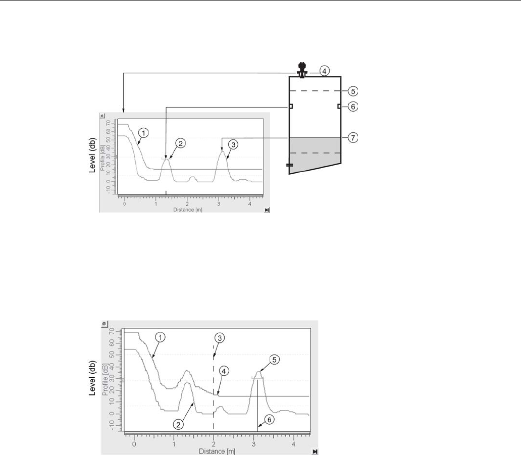
Appendix A: Technical reference
A.2 Echo processing
SITRANS LR250 (FOUNDATION FIELDBUS)
272 Operating Instructions, 08/2014, A5E32221411-AC
Example before Auto False Echo Suppression
①
Default TVT
⑤
High calibration point = 0
②
False echo
⑥
Obstruction at 1.3. m
③
Material echo
⑦
Material level at 3.2 m
④
Sensor reference point
Example after Auto False Echo Suppression
Auto False Echo
Suppression
Range set to 2 m
① Learned TVT ④ Default TVT
② False echo ⑤ Material echo
③ Auto False Echo Suppression Range ⑥ Echo marker
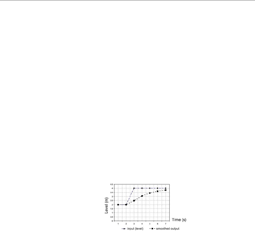
Appendix A: Technical reference
A.2 Echo processing
SITRANS LR250 (FOUNDATION FIELDBUS)
Operating Instructions, 08/2014, A5E32221411-AC 273
A.2.8
Measurement Range
Near Range (2.5.1.)
Near Range programs SITRANS LR250 to ignore the zone in front of the antenna. The default
blanking distance is 50 mm (1.97") from the end of the antenna.
Near Range allows you to increase the blanking value from its factory default. But
Auto False
Echo Suppression (2.5.10.1.)
is generally recommended in preference to extending the blanking
distance from factory values.
Far Range (2.5.2.)
Far Range can be used in applications where the base of the vessel is conical or parabolic. A
reliable echo may be available below the vessel empty distance, due to an indirect reflection
path.
Increasing Far Range to 30% or 40% can provide stable empty vessel readings.
A.2.9
Damping
Filter Time Constant (2.6.7.1)
smooths out the response to a sudden change in level. This is an
exponential filter and the engineering unit is always in seconds.
In 5 time constants the output rises exponentially: from 63.2% of the change in the first time
constant, to almost 100% of the change by the end of the 5th time constant.
Damping example
time constant = 2 seconds
input (level) change = 2 m
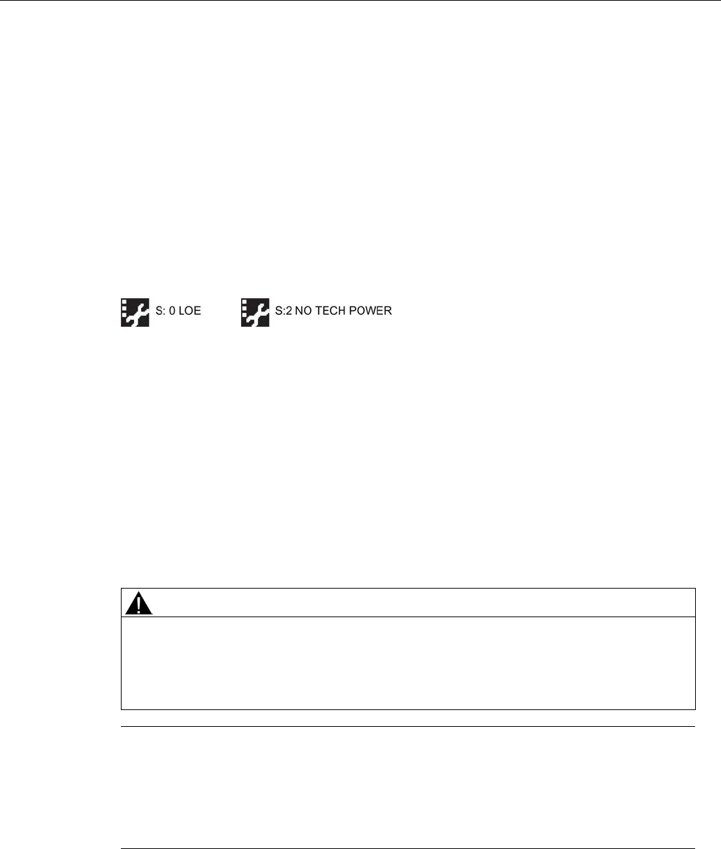
Appendix A: Technical reference
A.3 Maximum Process Temperature Chart
SITRANS LR250 (FOUNDATION FIELDBUS)
274 Operating Instructions, 08/2014, A5E32221411-AC
A.2.10
Loss of Echo (LOE)
A loss of echo (LOE) occurs when the calculated measurement is judged to be unreliable
because the echo confidence value has dropped below the echo confidence threshold.
Confidence (2.5.9.1.)
describes the quality of an echo. Higher values represent higher quality.
Echo Threshold (2.5.7.3.)
defines the minimum confidence value required for an echo to be
accepted as valid and evaluated.
If the LOE condition persists beyond the time limit set in
LOE Timer (2.3.6.)
the LCD displays the
Service Required icon, and the text region displays the fault code
S: 0
and the text
LOE
.
If two faults are present at the same time, the fault code, error text, and error icon for each fault
are displayed alternately. For example, Loss of Echo and faulty power supply:
Upon receiving a reliable echo, the loss of echo condition is aborted, the Service Required icon
and error message are cleared, and the reading returns to the current level.
A.2.10.1
LOE Timer
Loss of Echo (LOE) Timer (2.3.6.)
determines the length of time a Loss of Echo (LOE) condition
will persist before the function block will show a status of BAD or UNCERTAIN. The default is
100 seconds.
A.3
Maximum Process Temperature Chart
WARNING
Exceeded maximum internal and process temperatures
Danger of device malfunction
• Internal temperature must not exceed +80 ° C (+176 °F).
• Process temperature must not exceed limits specified by the antenna type.
Note
• The chart below is for guidance only.
• The chart does not represent every possible process connection arrangement. For
example, it will NOT apply if you are mounting SITRANS LR250 directly on a metallic
vessel surface.
• The chart does not take into consideration heating from direct sunlight exposure.
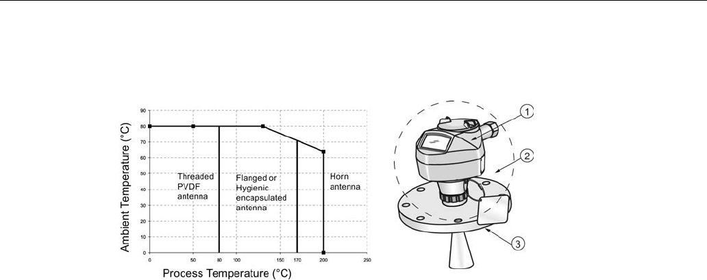
Appendix A: Technical reference
A.3 Maximum Process Temperature Chart
SITRANS LR250 (FOUNDATION FIELDBUS)
Operating Instructions, 08/2014, A5E32221411-AC 275
Maximum Process Temperatures versus allowable ambient
① Internal enclosure temperature
② Ambient temperature
③ Process temperature (at process
connection)
Where the chart does not apply, please use your own judgement regarding the use of SITRANS
LR250.
If the internal temperature exceeds the maximum allowable limit, a sun shield or a longer nozzle
may be required.
See
Minimum Value (3.3.1.)
and
Maximum Value (3.3.2.)
to monitor the Internal Temperature.

Appendix A: Technical reference
A.4 Process Pressure/Temperature derating curves
SITRANS LR250 (FOUNDATION FIELDBUS)
276 Operating Instructions, 08/2014, A5E32221411-AC
A.4
Process Pressure/Temperature derating curves
WARNING
Exceeded maximum permissible operating pressure
Danger of injury or poisoning.
The maximum permissible operating pressure depends on the device version. The device
can be damaged if the operating pressure is exceeded. Hot, toxic and corrosive process
media could be released.
• Make sure that the device is suitable for the maximum permissible operating pressure of
your system.
DANGER
Pressure applications
Danger to personnel, system and environment will result from improper disassembly.
• Never attempt to loosen, remove, or disassemble process connection while vessel
contents are under pressure.
WARNING
Pressure applications
Danger to personnel, system and environment can result from improper installation.
• Improper installation may result in loss of process pressure.
WARNING
Unsuitable connecting parts
Danger of injury or poisoning.
In case of improper mounting hot, toxic and corrosive process media could be released at
the connections.
• Ensure that connecting parts (such as flange gaskets and bolts) are suitable for
connection and process media.

Appendix A: Technical reference
A.4 Process Pressure/Temperature derating curves
SITRANS LR250 (FOUNDATION FIELDBUS)
Operating Instructions, 08/2014, A5E32221411-AC 277
Note
Material compatibility
Siemens can provide you with support concerning selection of sensor component
s wetted by
process media. However, you are responsible for the selection of components. Siemens
accepts no liability for faults or failures resulting from incompatible materials.
A.4.1
Pressure Equipment Directive, PED, 97/23/EC
Siemens Level Transmitters with flanged, threaded, or sanitary clamp type process mounts have
no pressure-bearing housing of their own and, therefore, do not come under the Pressure
Equipment Directive as pressure or safety accessories (see EU Commission Guideline 1/8 and
1/20).
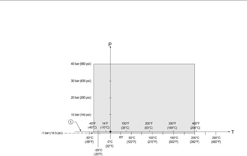
Appendix A: Technical reference
A.4 Process Pressure/Temperature derating curves
SITRANS LR250 (FOUNDATION FIELDBUS)
278 Operating Instructions, 08/2014, A5E32221411-AC
A.4.2
Horn antenna
1.5", 2" and 3" [NPT, G (BSPP), R (BSPT)] Threaded Versions
① Atmospheric
P Allowable operating pressures
T Allowable operating temperatures
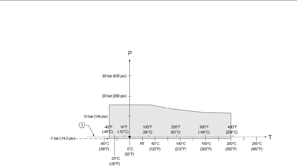
Appendix A: Technical reference
A.4 Process Pressure/Temperature derating curves
SITRANS LR250 (FOUNDATION FIELDBUS)
Operating Instructions, 08/2014, A5E32221411-AC 279
A.4.3
Flanged horn antenna
JIS B 2220, 10K: 50A, 80A, and 100A
① Atmospheric
P Allowable operating pressures
T Allowable operating temperatures
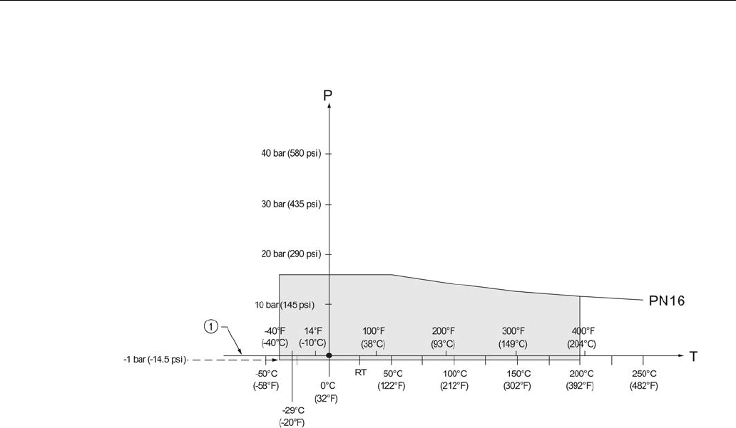
Appendix A: Technical reference
A.4 Process Pressure/Temperature derating curves
SITRANS LR250 (FOUNDATION FIELDBUS)
280 Operating Instructions, 08/2014, A5E32221411-AC
EN1092-1, PN16: DN50, DN80, DN100, and DN150
① Atmospheric
P Allowable operating pressures
T Allowable operating temperatures
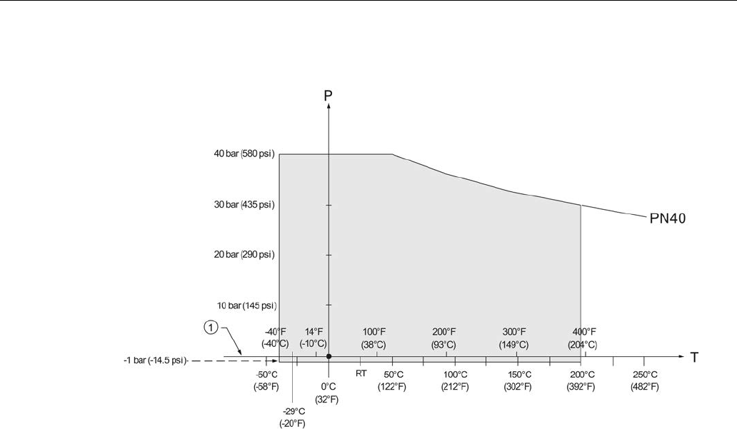
Appendix A: Technical reference
A.4 Process Pressure/Temperature derating curves
SITRANS LR250 (FOUNDATION FIELDBUS)
Operating Instructions, 08/2014, A5E32221411-AC 281
EN1092-1, PN40: DN50, DN80, DN100, and DN150
① Atmospheric
P Allowable operating pressures
T Allowable operating temperatures
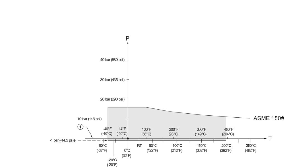
Appendix A: Technical reference
A.4 Process Pressure/Temperature derating curves
SITRANS LR250 (FOUNDATION FIELDBUS)
282 Operating Instructions, 08/2014, A5E32221411-AC
ASME B16.5, Class 150: 2", 3", and 4" NPS
① Atmospheric
P Allowable operating pressures
T Allowable operating temperatures
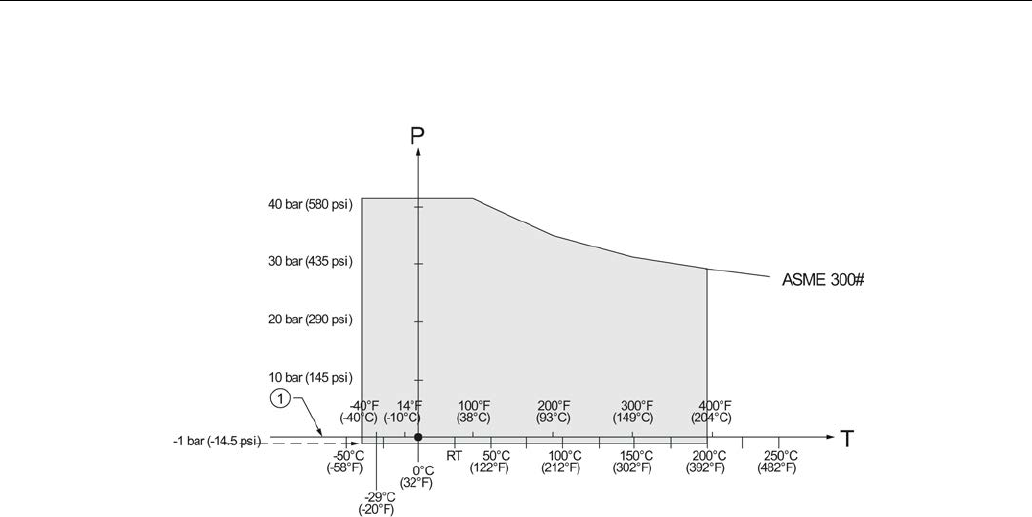
Appendix A: Technical reference
A.4 Process Pressure/Temperature derating curves
SITRANS LR250 (FOUNDATION FIELDBUS)
Operating Instructions, 08/2014, A5E32221411-AC 283
ASME B16.5, Class 300: 2", 3", and 4" NPS
① Atmospheric
P Allowable operating pressures
T Allowable operating temperatures
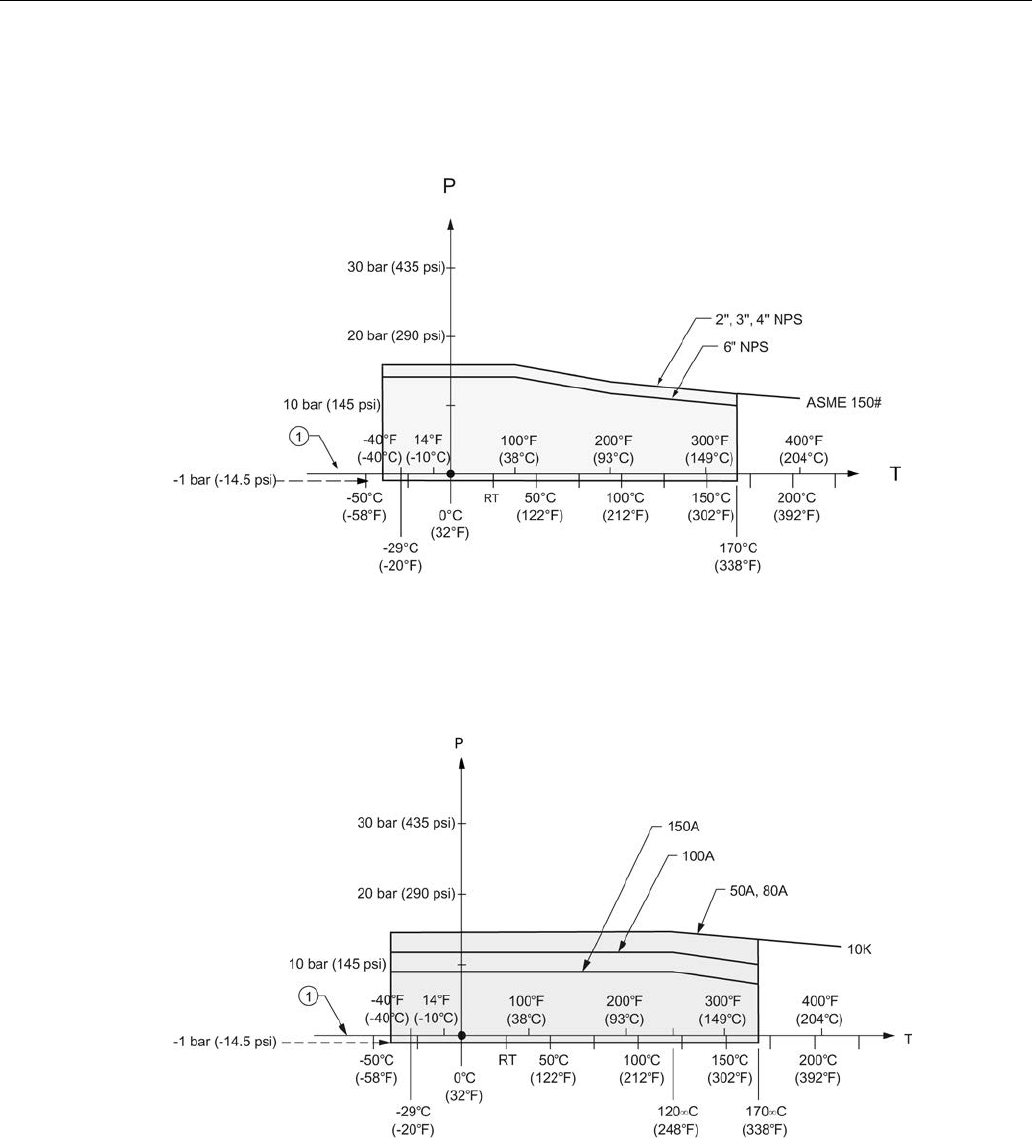
Appendix A: Technical reference
A.4 Process Pressure/Temperature derating curves
SITRANS LR250 (FOUNDATION FIELDBUS)
284 Operating Instructions, 08/2014, A5E32221411-AC
A.4.4
Flanged encapsulated antenna
ASME B16.5, Class 150: 2", 3", 4", and 6" NPS
①
Atmospheric
P
Allowable operating pressures
T
Allowable operating temperatures
JIS B 2220, 10K: 50A, 80A, 100A, and 150A
①
Atmospheric
P
Allowable operating pressures
T
Allowable operating temperatures
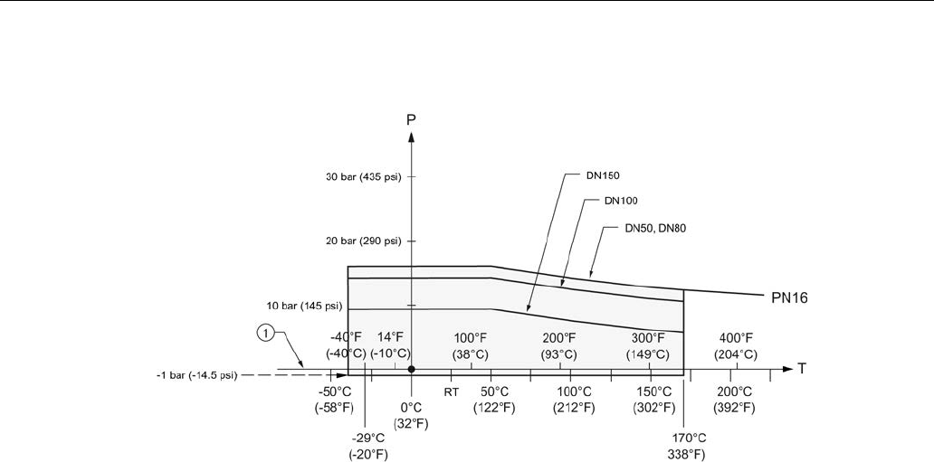
Appendix A: Technical reference
A.4 Process Pressure/Temperature derating curves
SITRANS LR250 (FOUNDATION FIELDBUS)
Operating Instructions, 08/2014, A5E32221411-AC 285
EN1092-1, PN10/16: DN50, DN80, DN100, and DN150
①
Atmospheric
P
Allowable operating pressures
T
Allowable operating temperatures
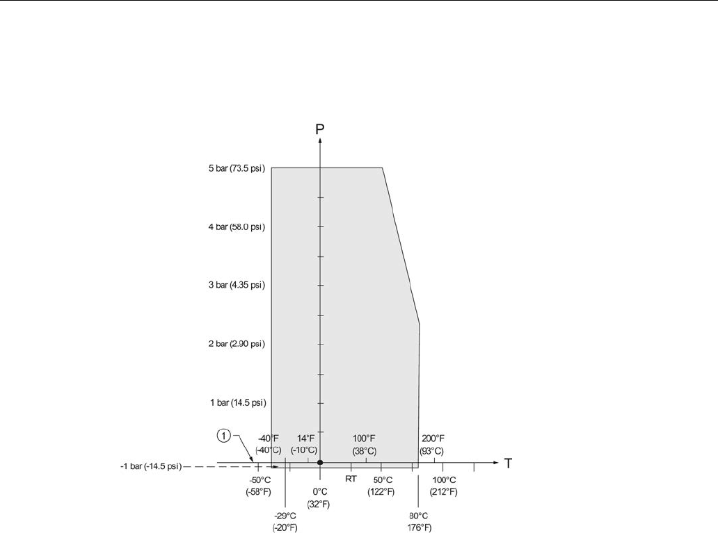
Appendix A: Technical reference
A.4 Process Pressure/Temperature derating curves
SITRANS LR250 (FOUNDATION FIELDBUS)
286 Operating Instructions, 08/2014, A5E32221411-AC
A.4.5
PVDF antenna
ASME B1.20.1 2" NPT, EN ISO 228-1 2" G (BSPP), EN 10226-1 2" R (BSPT)
① Atmospheric
P Allowable operating pressures
T Allowable operating temperatures
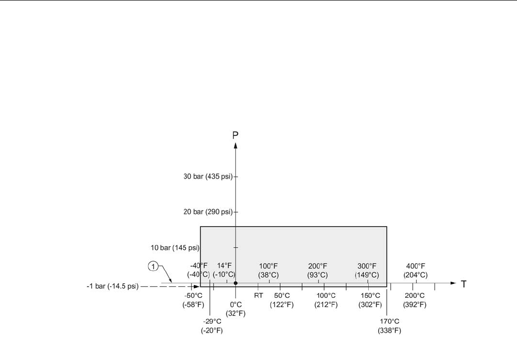
Appendix A: Technical reference
A.4 Process Pressure/Temperature derating curves
SITRANS LR250 (FOUNDATION FIELDBUS)
Operating Instructions, 08/2014, A5E32221411-AC 287
A.4.6
Hygienic encapsulated antenna
DIN 11851 Sanitary/Hygienic nozzle/slotted nut: DN50, DN80, and DN100
DIN 11864-1 Aseptic/Hygienic nozzle/slotted nut: DN50, DN80, and DN100
① Atmospheric
P Allowable operating pressures
T Allowable operating temperatures
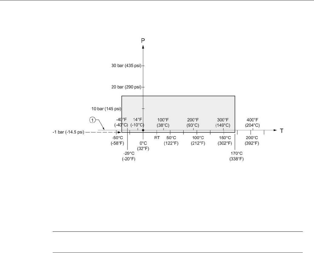
Appendix A: Technical reference
A.4 Process Pressure/Temperature derating curves
SITRANS LR250 (FOUNDATION FIELDBUS)
288 Operating Instructions, 08/2014, A5E32221411-AC
DIN 11864-2 Aseptic/Hygienic flanged: DN50, DN80, and DN100
① Atmospheric
P Allowable operating pressures
T Allowable operating temperatures
Note
For pressure applications, all attachment hardware must be suitably rated.
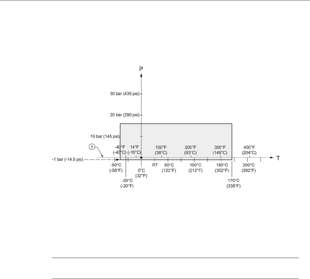
Appendix A: Technical reference
A.4 Process Pressure/Temperature derating curves
SITRANS LR250 (FOUNDATION FIELDBUS)
Operating Instructions, 08/2014, A5E32221411-AC 289
DIN 11864-3 Aseptic/Hygienic clamp: DN50, DN80, and DN100
IS0 2852 Sanitary/Hygienic clamp: 2", 3", and 4"
Tuchenhagen Varivent face seal clamp: Type N (68 mm) and Type F (50 mm)
① Atmospheric
P Allowable operating pressures
T Allowable operating temperatures
Note
For pressure applications, all clamps must be rated accordingly.

Appendix A: Technical reference
A.4 Process Pressure/Temperature derating curves
SITRANS LR250 (FOUNDATION FIELDBUS)
290 Operating Instructions, 08/2014, A5E32221411-AC

SITRANS LR250 (FOUNDATION FIELDBUS)
Operating Instructions, 08/2014, A5E32221411-AC 291
Appendix B: Communications via Foundation
Fieldbus
B
SITRANS LR250 (Foundation Fieldbus) is an FF (H1) device of Class 31PS, and 32L. It
supports publish and subscribe functionality as well as Backup LAS functionality. The full range
of SITRANS LR250 functions is available only over an FF network.
Foundation Fieldbus (FF) is an open industrial protocol. Full details about FF can be obtained
from:
Foundation Fieldbus (http://www.fieldbus.org/)
For details on the use of Foundation Fieldbus protocol with Siemens FF level instruments, see
manual
Foundation Fieldbus for Level Instruments
(7ML19985MP01). The manual is available
on the CD of Siemens manuals, included in the box with your Siemens level instrument, or for
other Siemens level measurement manuals, go to:
Siemens level (http://www.siemens.com/level)
Look under
Level Measurement
.
B.1
Field Communicator 375 (F375)
This device supports Field Communicator 375 (FC375). The FC375 menu structure is very
similar to the menu structure for AMS Device Manager [see AMS Menu Structure (Page 79).]

Appendix B: Communications via Foundation Fieldbus
B.1 Field Communicator 375 (F375)
SITRANS LR250 (FOUNDATION FIELDBUS)
292 Operating Instructions, 08/2014, A5E32221411-AC

SITRANS LR250 (FOUNDATION FIELDBUS)
Operating Instructions, 08/2014, A5E32221411-AC 293
Appendix C: Certificates and support
C
C.1
Certificates
Certificates can be downloaded from our website at:
Product page (http://www.siemens.com/LR250).
C.2
Technical support
If you have any technical questions about the device described in these Operating Instructions
and do not find the right answers, you can contact Customer Support:
● Via the Internet using the
Support Request:
Support request (http://www.siemens.com/automation/support-request)
● Via Phone:
– Europe: +49 (0)911 895 7222
– America: +1 423 262 5710
– Asia-Pacific: +86 10 6475 7575
Further information about our technical support is available on the Internet at
Technical support (http://support.automation.siemens.com/WW/view/en/16604318)
Service & Support on the Internet
In addition to our documentation, we offer a comprehensive knowledge base online on the
Internet at:
Service & Support (http://www.siemens.com/automation/service&support)
There you will find:
● The latest product information, FAQs, downloads, tips and tricks.
● Our newsletter, providing you with the latest information about your products.
● Our bulletin board, where users and specialists share their knowledge worldwide.
● You can find your local contact partner for Industry Automation and Drives Technologies in
our partner database.
● Information about field service, repairs, spare parts and lots more under "Services."

Appendix C: Certificates and support
C.2 Technical support
SITRANS LR250 (FOUNDATION FIELDBUS)
294 Operating Instructions, 08/2014, A5E32221411-AC
Additional Support
Please contact your local Siemens representative and offices if you have additional questions
about the device
Find your contact partner at:
Local contact person (http://www.siemens.com/automation/partner)

SITRANS LR250 (FOUNDATION FIELDBUS)
Operating Instructions, 08/2014, A5E32221411-AC 295
List of abbreviations
13
Short form
Long form
Description
Units
3-A 3-A Sanitary Standards, Inc.
AIFB Analog Input Function Block
CE / FM / CSA Conformité Européene / Factory Mutual
/ Canadian Standards Association
safety approval
Ci Internal capacitance F
D/A Dialog to analog
DCS Distributed Control System control room apparatus
dK dielectric constant
EDD Electronic Device Description
EHEDG European Hygienic Engineering Design
Group
FEA Flanged encapsulated antenna
FDA Food and Drug Administration
HEA Hygienic encapsulated antenna
Ii Input current mA
Io Output current mA
IS Intrinsically Safe safety approval
Li Internal inductance mH
mH milliHenry 10-3 H
μF microFarad 10-6 F
μs microsecond 10-6 s
PED Pressure Equipment Directive safety approval
pF pico Farads 10-12 F
ppm parts per million
PV Primary Variable measured value
PVDF Polyvinylidene fluoride
SELV Safety extra low voltage
SV Secondary Variable equivalent value
TB Transducer Block
TVT Time Varying Threshold sensitivity threshold
TFM1600 PTFE Modified PTFE polytetrafluoroethylene
with perfluoropropyl
vinyl ether (PPVE)
modifier
Ui Input voltage V
Uo Output voltage V

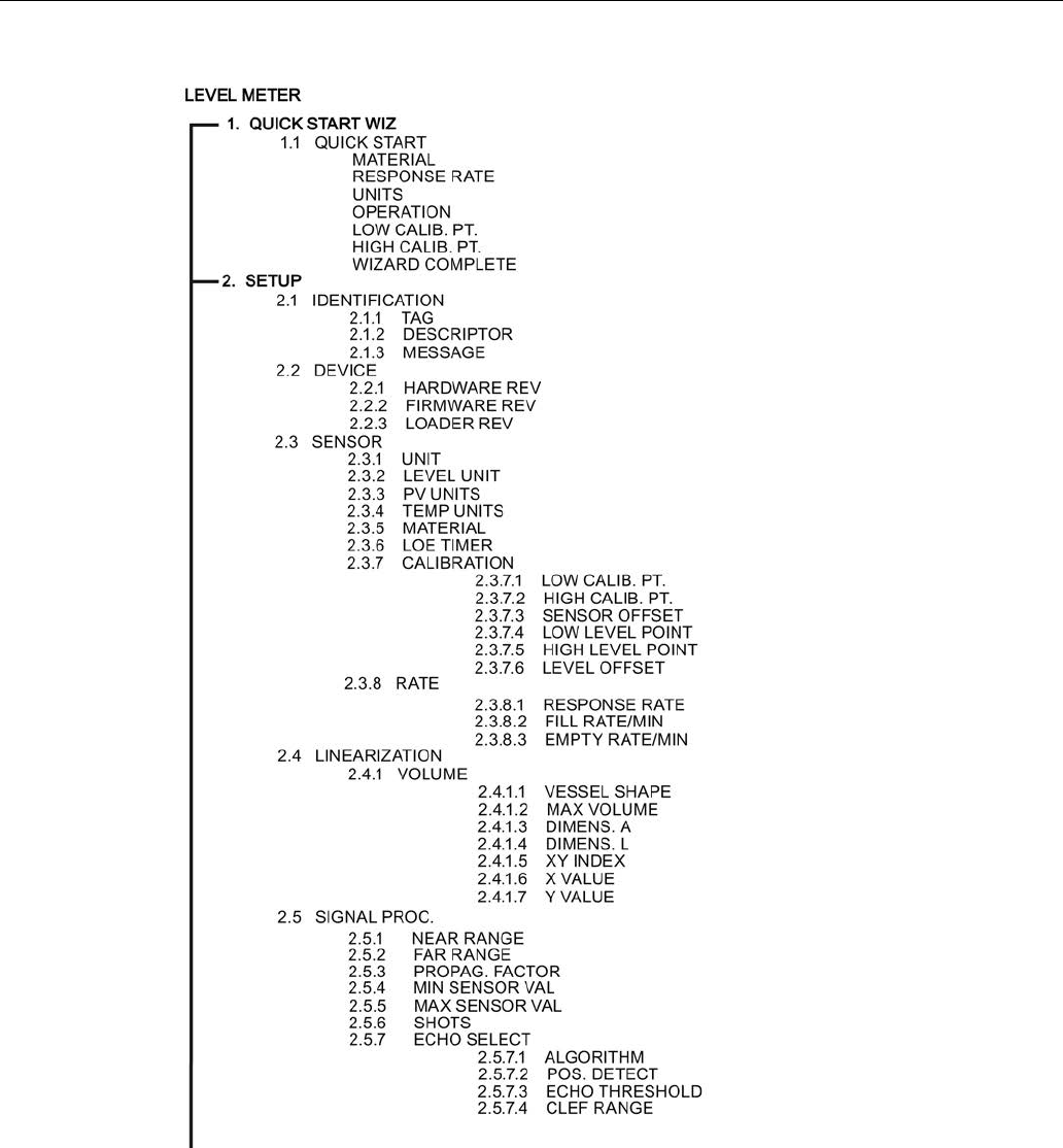
LCD menu structure
SITRANS LR250 (FOUNDATION FIELDBUS)
Operating Instructions, 08/2014, A5E32221411-AC 297
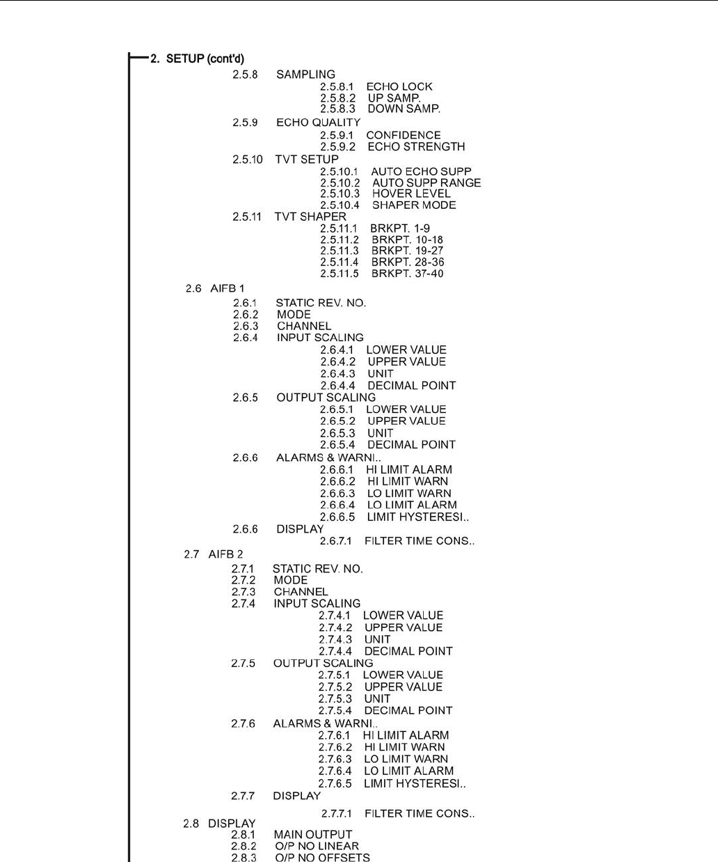
LCD menu structure
SITRANS LR250 (FOUNDATION FIELDBUS)
298 Operating Instructions, 08/2014, A5E32221411-AC
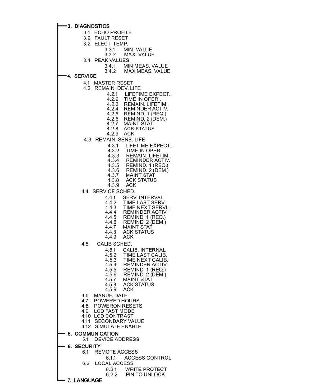
LCD menu structure
SITRANS LR250 (FOUNDATION FIELDBUS)
Operating Instructions, 08/2014, A5E32221411-AC 299
SITRANS LR250 (FOUNDATION FIELDBUS)
Operating Instructions, 08/2014, A5E32221411-AC 301
Glossary
accuracy
degree of conformity of a measure to a standard or a true value.
algorithm
a prescribed set of well-defined rules or processes for the solution of a problem in a finite
number of steps.
ambient temperature
the temperature of the surrounding air that comes in contact with the enclosure of the device.
antenna
an aerial which sends out and receives a signal in a specific direction. There are four basic types
of antenna in radar level measurement, horn, parabolic, rod, and waveguide.
Auto False-Echo Suppression
a technique used to adjust the level of a TVT to avoid the reading of false echoes. (See TVT.)
Auto-False Echo Suppression Range
defines the endpoint of the learned TVT distance. (See TVT.) This is used in conjunction with
auto false echo suppression.
beam angle
the angle diametrically subtended by the one-half power limits (-3 dB) of the microwave beam.
blanking
a blind zone extending away from the reference point plus any additional shield length.The
device is programmed to ignore this zone.

Glossary
SITRANS LR250 (FOUNDATION FIELDBUS)
302 Operating Instructions, 08/2014, A5E32221411-AC
capacitance
the property of a system of conductors and dielectrics that permits the storage of electricity when
potential differences exist between the conductors. Its value is expressed as the ratio of a
quantity of electricity to a potential difference, and the unit is a Farad.
confidence
see Echo Confidence.
damping
term applied to the performance of a device to denote the manner in which the measurement
settles to its steady indication after a change in the value of the level.
dB (decibel)
a unit used to measure the amplitude of signals.
derating
to decrease a rating suitable for normal conditions according to guidelines specified for different
conditions.
dielectric
a nonconductor of direct electric current. Many conductive liquids/electrolytes exhibit dielectric
properties; the relative dielectric constant of water is 80.
dielectric constant (dK)
the ability of a dielectric to store electrical potential energy under the influence of an electric field.
Also known as Relative Permittivity. An increase in the
dielectric constant is directly proportional to an increase in signal amplitude. The value is usually
given relative to a vacuum /dry air: the dielectric constant of air is 1. Many conductive
liquids/electrolytes exhibit dielectric properties; the relative dielectric constant of water is 80.
echo
a signal that has been reflected with sufficient magnitude and delay to be perceived in some
manner as a signal distinct from that directly transmitted. Echoes are frequently measured in
decibels relative to the directly transmitted signal.

Glossary
SITRANS LR250 (FOUNDATION FIELDBUS)
Operating Instructions, 08/2014, A5E32221411-AC 303
Echo Confidence
describes the quality of an echo. Higher values represent higher quality. Echo Threshold defines
the minimum value required for an echo to be accepted as valid and evaluated.
Echo Lock Window
a window centered on an echo in order to locate and display the echo’s position and true
reading. Echoes outside the window are not immediately processed.
Echo Marker
a marker that points to the processed echo.
Echo Processing
the process by which the radar unit determines echoes.
Echo Profile
a graphical display of a processed echo.
Echo Strength
describes the strength of the selected echo in dB referred to 1 μV rms.
false echo
any echo which is not the echo from the desired target. Generally, false echoes are created by
vessel obstructions.
frequency
the number of periods occurring per unit time. Frequency may be stated in cycles per second.
hertz (Hz):
unit of frequency, one cycle per second. 1 Gigahertz (GHz) is equal to 109 Hz.
horn antenna
a conical, horn-shaped antenna which focuses microwave signals. The larger the horn diameter,
the more focused the radar beam.

Glossary
SITRANS LR250 (FOUNDATION FIELDBUS)
304 Operating Instructions, 08/2014, A5E32221411-AC
inductance
the property of an electric circuit by virtue of which a varying current induces an electromotive
force in that circuit or in a neighboring circuit. The unit is a Henry.
multiple echoes
secondary echoes that appear as double, triple, or quadruple echoes in the distance from the
target echo.
Near Blanking
see Blanking.
nozzle
a length of pipe mounted onto a vessel that supports the flange.
parameters
in programming, variables that are given constant values for specific purposes or processes.
polarization
the property of a radiated electromagnetic wave describing the time-varying direction and
amplitude of the electric field vector.
propagation factor (pf)
where the maximum velocity is 1.0, pf is a value that represents a reduction in propagation
velocity as a result of the wave travelling through a pipe or medium.
pulse radar
a radar type that directly measures distance using short microwave pulses. Distance is
determined by the return transit time.
radar
radar is an acronym for RAdio Detection And Ranging. A device that radiates electromagnetic
waves and utilizes the reflection of such waves from distant objects to determine their existence
or position.

Glossary
SITRANS LR250 (FOUNDATION FIELDBUS)
Operating Instructions, 08/2014, A5E32221411-AC 305
range
distance between a transmitter and a target.
range extension
the distance below the zero percent or empty point in a vessel.
relative humidity
the ratio of the actual amount of moisture in the atmosphere to the maximum amount of moisture
the atmosphere could hold (which varies depending on the air temperature).
repeatability
the closeness of agreement among repeated measurements of the same variable under the
same conditions.
shot
one transmit pulse or measurement.
stilling-well
see stillpipe.
stillpipe
a pipe that is mounted inside a vessel parallel to the vessel wall, and is open to the vessel at the
bottom.
TVT (Time Varying Threshold)
a time-varying curve that determines the threshold level above which echoes are determined to
be valid.

Glossary
SITRANS LR250 (FOUNDATION FIELDBUS)
306 Operating Instructions, 08/2014, A5E32221411-AC
SITRANS LR250 (FOUNDATION FIELDBUS)
Operating Instructions, 08/2014, A5E32221411-AC 307
Index
A
Abbreviations and identifications list, 295
access control
local access, 189
remote access, 188
activating LR250, 56
agitator blade detection
avoiding, 160
AMS Device Manager
features, 81
antenna
replacement, 199
antenna types
flanged encapsulated antenna, 231, 233
flanged horn antenna, 227
flanged horn antenna with extension, 229
threaded horn, 221
threaded PVDF antenna, 252
Auto False Echo Suppression
explanation, 271
setup, 162
B
beam angle
flanged encapsulated antenna, 231, 233
flanged horn, 227, 229
threaded horn, 223
threaded PVDF antenna, 252
blanking (see Near Range), 273
bolting instructions, 38
bypass pipe
see stillpipe, 32
C
cables
requirements, 42
Calibration Interval, 183
channel
transducer block outputs, 168
cleaning
instructions, 197
CLEF (Constrained Leading Edge Fit)
explanation, 268
CLEF range
setup, 159
conduits
requirements, 42
configuration
new device via AMS, 85
Quick Start via LUI, 65
Correct usage, (see Improper device modifications)
D
damping
Filter Time Constant setup, 171
Damping
explanation, 273
Device Address, 187
device nameplate
FM/CSA Class 1 Div. 2, 51
Intrinsically Safe (ATEX/IECEx), 48
Intrinsically Safe (FM/CSA), 48
Device Reset
see Master Reset, 175
Device Status
icons, 204
Diagnostics
maintenance settings, 172
dimensions
flanged encapsulated antenna, 231, 233
flanged horn, 227, 229
flat face flange, 259
raised face flange, 253, 256
threaded horn with extension, 223
threaded PVDF antenna, 252
E
echo confidence
parameter setup, 161

Index
SITRANS LR250 (FOUNDATION FIELDBUS)
308 Operating Instructions, 08/2014, A5E32221411-AC
echo processing
Process Intelligence, 266
Echo Profile
view via LUI, 70
echo selection
Algorithm, 267
CLEF (Constrained Leading Edge Fit), 268
Position algorithm, 267
time varying threshold (TVT), 266
edit mode
handheld programmer, 61
key functions, 64
Empty rate
setup, 150
enable/disable remote operation, 188
enclosure
opening, 43
F
factory defaults
Master Reset, 175
false echo
see Auto False Echo Suppression, 271
Far Range
explanation, 273
setup, 156
fault codes
general fault codes, 205
Fill Rate
setup, 149
Filter Time Constant
explanation, 273
flange
bolting instructions, 38
flange markings
flat face, 259
raised face, 254, 257
flange sizes
flat face, 259
raised face, 253, 256
flanged encapsulated antenna
dimensions, 233
flanged horn
dimensions, 227, 229
H
handheld programmer
edit mode, 63
navigation, 62
programming, 60
hazardous area installations
instructions, 52
wiring requirements, 46
hysteresis
setup, 171
I
Identifications and abbreviations
list, 295
Improper device modifications, 17
installation
hazardous area requirements, 46
requirements, 34
warnings and notes, 34
internal temperature
monitoring, 274
K
key functions
edit mode, 64
navigation mode, 62
L
Language, 190
LCD display
contrast adjustment, 186
echo profile viewing, 70
fast mode, 186
measurement mode, 57
lens
replacement, 199
lid-lock set screw, 43
Limit Hysteresis
setup, 171
Lithium batteries
Safety, 55
Local User Interface (LUI), 57

Index
SITRANS LR250 (FOUNDATION FIELDBUS)
Operating Instructions, 08/2014, A5E32221411-AC 309
LOE Timer
explanation, 274
setup, 147
loop voltage vs. loop resistance
power supply requirements, 48
loss of echo (LOE)
explanation, 274
Loss of Echo (LOE)
explanation, 274
LUI (Local User Interface)
contrast adjustment, 57
M
maintenance
repairs, 197
replacing antenna, 199
replacing lens, 199
Maintenance, 198
maintenance settings
Calibration Interval, 183
see Diagnostics, 172
see Remaining Sensor Lifetime, 179
Service Interval, 181
Master Reset
factory defaults, 175
measurement range
blanking via Near Range, 273
extension via Far Range, 273
Measurement Response
explanation, 270
mounting
bypass requirements, 32
handheld programmer access, 30
housing construction, 24, 31
nozzle design, 27
nozzle location, 28
on vessel with obstructions, 31
sunshield recommended, 31
N
nameplate
Intrinsically Safe (ATEX/IECEx), 48
Intrinsically Safe (FM/CSA), 48
Near Range
explanation, 273
setup, 155
O
operating principles
cleaning, 265
Output limits
setup, 170
Output Scale
setup, 169
overview, 19
P
password protection
via AMS, 129
PED (Pressure Equipment Directive), 23, 277
performance
specifications, 213
pipe sizes
flange mounting, 253, 256
polarization reference point, 31
power source
requirements, 42
power supply requirements
loop voltage vs. loop resistance, 48
pressure applications, 23
Pressure Equipment Directive, 23, 277
Process Intelligence, 266
process temperature
maximum, 274
programmer
handheld, 59
programming
via the handheld programmer, 60
propogation factor
values, 156
Q
Qualified personnel, 18
Quick Start Wizard
via LUI, 65
R
raised face flange markings, 253, 255
reading erratic
troubleshooting, 211

Index
SITRANS LR250 (FOUNDATION FIELDBUS)
310 Operating Instructions, 08/2014, A5E32221411-AC
reading incorrect
troubleshooting, 211
reading response slow, 211
Remote Lockout, 188
repair
cautions, 199
excluded liability, 199
reset
see Master Reset, 175
Response Rate
explanation, 270
setup, 149
S
safety notes, 15
Scope of delivery, 13
security
local access unlock value, 189
password protection via AMS, 129
sensor reference point
flanged encapsulated antenna, 231, 233
flanged horn, 227, 229
flat faced flange, 259
raised face flange, 253, 255
threaded horn, 223
threaded PVDF horn, 252
sidepipe
see bypass pipe, 32
SITRANS LR250
operating principles, 265
startup
transition screen, 56
stillpipe
mounting requirements, 32
Support
contact information, 293
T
technical data, 213
ambient temperature, 218
antenna, 216
enclosure, 216
environmental, 218
performance, 213
power, 213
pressure, 218
process connections, 215
process temperature, 218
weight, 216
technical support
contact information, 293
threaded connection markings, 252
threaded horn antenna
dimensions, 223
threaded PVDF antenna
dimensions, 252
transducer block outputs
channel, 168
troubleshooting
communication, 203
operation, 210
TVT (time varying threshold)
explanation, 266
V
vessel shape
selection, 151
W
wiring
cables, 42
hazardous areas, 46
Write Protection, 189