Siemens Canada Siemens Milltronics Process Instruments LR400 SITRANS LR 400 User Manual sitranslrd3
Siemens Canada Ltd. - Siemens Milltronics Process Instruments SITRANS LR 400 sitranslrd3
Contents
- 1. users manual 1
- 2. users manual 2
- 3. users manual 3
users manual 1
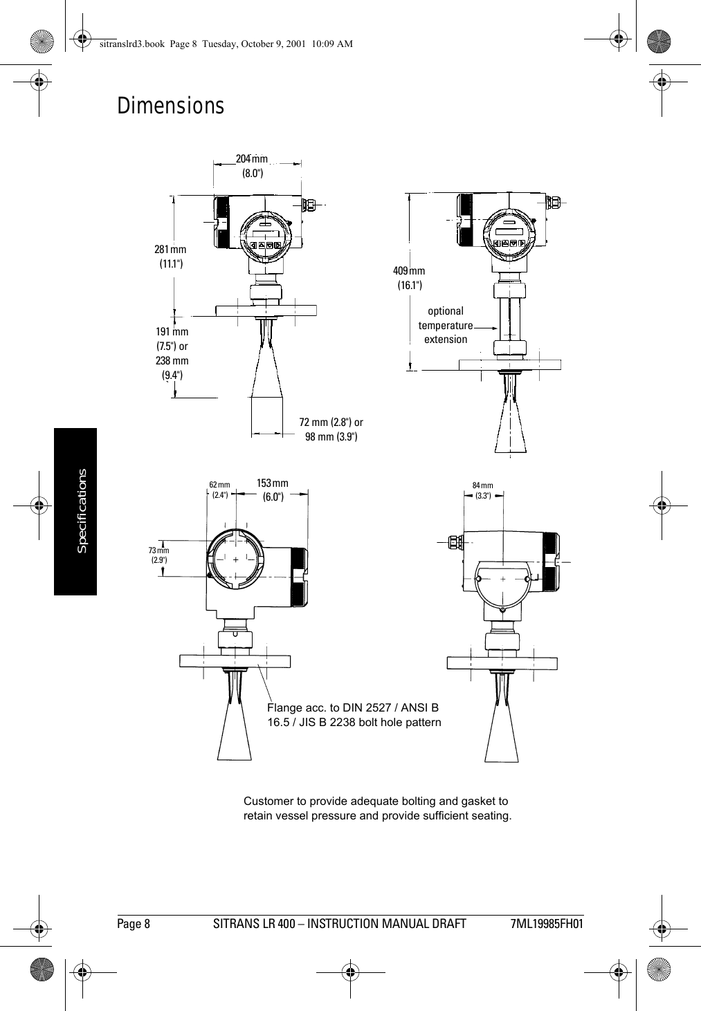
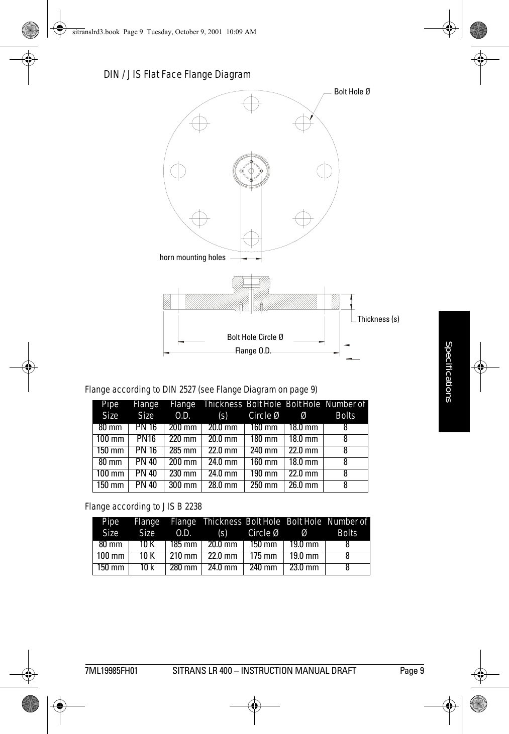
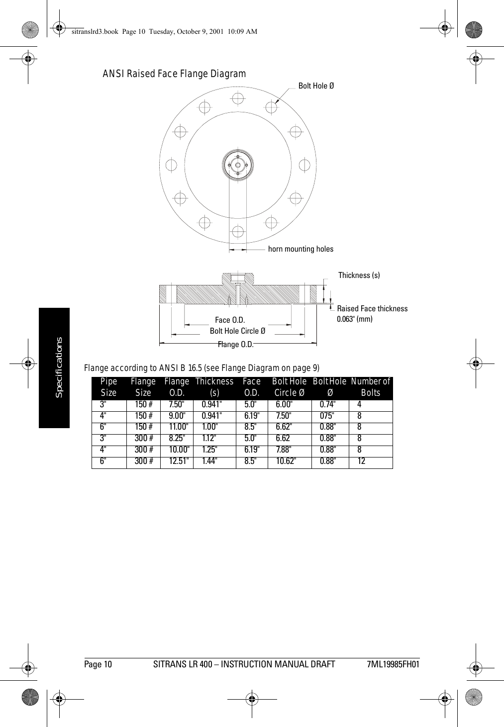
![7ML19985FH01 SITRANS LR 400 – INSTRUCTION MANUAL DRAFT Page 5mmmmmSpecificationsMechanical• Nominal sizes DIN DN 80 DN 100 DN 150ANSI 3" 4" 6"JIS 80 mm 100 mm 150 mm• Pressure classesDIN PN16 PN40ANSI 150 lb 300lbJIS 10KFlange• Process Connection Flange DIN 2527, ANSI B16.5, or JIS B2238 equivalent boltpattern• Materials of the wetted Stainless steel, material–no. 1.4571 and 1.4581, PTFEparts –in contact with (or glass/PTFE, Zone 0 and Zone 20 devices)the processEnclosure• construction Die-cast aluminum, painted• conduit M20 (cable diameter 6 to 9.5 mm[0.24 to 0.37"])or ½”-14 NPT• ingress protection Type 4X/NEMA 4X, Type 6/NEMA 6, IP 671Weight• Weight of unit and flange1.Use only approved, suitable sized hubs for watertight applications.Flange Pressure Class Size WeightDIN 2527 PN 16 DN 80 11.9 kg (26.1 lbs)DN 100 13.2 kg (28.9 lbs)DN 150 19.2 kg (42.1 lbs)PN 40 DN 80 12.9 kg (28.4 lbs)DN 100 15.5 kg (34.1 lbs)DN 150 24.1 kg (43.1 lbs)ANSI B 16.5 150 lb 3" 12.2 kg (26.8 lbs)4" 14.8 kg (32.5 lbs)6" 20.1 kg (44.2 lbs)300 lb 3" 14.3 kg (31.5 lbs)4" 20.2 kg (44.4 lbs)6" 31.8 kg (69.9 lbs)JIS B2238 10K 80 mm 11.9 kg (26.1 lbs)100 mm 13.2 kg (28.9 lbs)150 mm 19.2 kg (42.1 lbs)sitranslrd3.book Page 5 Tuesday, October 9, 2001 10:09 AM](https://usermanual.wiki/Siemens-Canada-Siemens-Milltronics-Process-Instruments/LR400.users-manual-1/User-Guide-174191-Page-9.png)
![Page 6 SITRANS LR 400 – INSTRUCTION MANUAL DRAFT 7ML19985FH01mmmmmSpecificationsEnvironmentallocation: indoor/outdooraltitude: 2000 m maxambient temperature: -40 to 65°C (-40 to 149°F)relative humidity: suitable for outdoor (Type / Nema 4X, 6/ IP67)installation category IIpollution degree 4• *Process Temperature -40 to 140°C (-40 to 284°F),optional -40 to 240°C(-40 to 482°F) • Electromagnetic compatibilitySpurious emission according to EN 50 081Interference strength according to EN 50 082 and NAMUR• *Perm. ambient -40 to 65°C (-40 to 149°F) (non-hazardous version)temperature -20 to 65°C (-4 to 149°F) (hazardous version)LCD: -10 to 55 °C (14 to 131°F)Observe the temperature classes in hazardous areas!• Perm. storage -30 to 80°C (-22 to 176°F),temperatureApprovals (verify against device nameplate)• Explosion Protection Certificate No. PTB 00 ATEX 1024** Refer to device II 1/2G EEx d IIC T6II 2G EEx d IIC T6 nameplate II 1/2G EEx dem IIC T6II 2G EEx dem IIC T6II 1/2G EEx dem [ib] IIC T6II 2G EEx dem [ib] IIC T6II 1/2G EEx dem [ia] IIC T6II 2G EEx dem [ia] IIC T6Certificate No. DMT 01 ATEX E 038II 1/2 D IP 65 (dust zone 20, zone 21 approval)• General FM, CSAapproval pending• Radio FCC, Industry Canada, European Radioapproval pendingComunication• Communication:HARTLoad 230 to 600 Ω, 230 to 500 Ω when connecting a couplingmoduleLine two-wire shielded: ≤ 3 kmmulti-wire shielded: ≤ 1.5 kmProtocol HART, Version 5.1*Note: Refer to Process/Ambient de-rating curves in Appendix III.sitranslrd3.book Page 6 Tuesday, October 9, 2001 10:09 AM](https://usermanual.wiki/Siemens-Canada-Siemens-Milltronics-Process-Instruments/LR400.users-manual-1/User-Guide-174191-Page-10.png)
![7ML19985FH01 SITRANS LR 400 – INSTRUCTION MANUAL DRAFT Page 7mmmmmSpecificationsCommunication: Profibus PAProtocol Layer 1 and 2 Profibus PA, technology: IEC 61158-2, slave-functionalityDevice Class BDevice Profile 3.0• PC/Laptop requirements IBM-compatibleRAM ≥ 64 MbytesHard disk ≥ 100 MbytesRS 232-C interfaceVGA graphic card (≥ 640 x 480)• Software for PC/Laptop Windows 95/98 or NT 4.0SIMATIC PDMPerformanceMeasured value error (under reference conditions)• Measuring error ≤ ± 15 mm at 0.26 to 2 m distance≤ ± 5 mm at 2 to 10 m distance≤ ± 15 mm at 10 to 45 m distance(see diagram below)• Dead zone 0-26 cm from bottom edge of flange• Additional contribution of ≤ 0.1 % of the measured valueAnalog Output ≤ 0.05 % of full scale• Additional Contribution of ≤ 0.05 % per 10 % deviation of UNthe Supply Voltage• Influence of pressure ≤ 0.3 % to 10 bar without pressure correction(air, 20°C) ≤ 2 % at 10 to 64 bar without pressure correction• Long-term stability ≤ ± 1 mm/year• Repetitive accuracy ≤ ± 1 mm at 0 to 45 m, damping ≥ 1 s• Reference conditionsMedium Triple reflector on the main axis of the antenna main lobeAmbient temperature 25 ± 5°C (77 ± 9°F)Ambient pressure 1050 mbar ± 10 %Absolute Measuring Error5101520Absolute measuring error [mm]10 20 30 40Distance from flange [m]452-20-15-10-50sitranslrd3.book Page 7 Tuesday, October 9, 2001 10:09 AM](https://usermanual.wiki/Siemens-Canada-Siemens-Milltronics-Process-Instruments/LR400.users-manual-1/User-Guide-174191-Page-11.png)
![Page 14 SITRANS LR 400 – INSTRUCTION MANUAL DRAFT 7ML19985FH01mmmmmInstallationMake the electrical connections as follows:1. Release the cover lock on the connection box with a 3 mm Allen key.2. Unscrew the cover from the connection box.3. Push the power cable and signal cable through the cable gland on the right of the unit., up to the terminal strip. Lay the cable in a bend before the cable gland so that moisture cannot enter the connection box.4. Connect the earth conductor of the power supply to the earth terminal in the connection box. Choose a length of cable so that the earth conductor is disconnected last when you pull the cable.5. In devices with ignition protection types II 1/2G EEx dem [ia] IIC T6 and II 1/2G EEx dem [ib] IIC T6 or II 2G EEx dem [ia] IIC T6 and II 2G EEx dem [ib] IIC T6, mount the cover for the power supply terminals.6. Tighten the cable screw gland and check the strain relief (pull and turn).7. In devices with ignition protection type II 1/2G EEx D IIC T6 or II 2G EEx d IIC T6, replace unused screw-type cable glands with a certified dummy plug.8. Screw the cover onto the housing and tighten it without using a tool. The sealing ring must be clean and undamaged.9. Mount the cover lock of the connection box cover.10. Connect the earth terminal located between the screw-type cable glands to a ground connection at your vessel by using a cable of a cross-section at least 2.5 mm2 wide.For error-free communication via the HART protocol, a load of at least 230 Ω must be available in the signal circuit.Warning: To avoid short-circuits, do not connect a load resistance with bare wires in the connection box.The housing cover may not be unscrewed in a hazardous area when the device is under voltage (power supply, digital outputs on external supply). In devices with ignition protection types II 1/2G EEx dem [ia] IIC T6 and II 1/2G EEx dem [ib] IIC T6 II 2G EEx dem [ia] IIC T6 and II 2G EEx dem [ib] IIC T6, only the cover of the connection box may be unscrewed for test purposes. The cover on the power supply terminals may not be removed!sitranslrd3.book Page 14 Tuesday, October 9, 2001 10:09 AM](https://usermanual.wiki/Siemens-Canada-Siemens-Milltronics-Process-Instruments/LR400.users-manual-1/User-Guide-174191-Page-18.png)
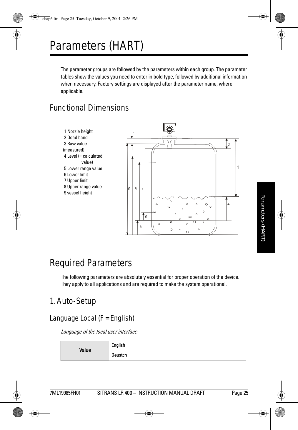
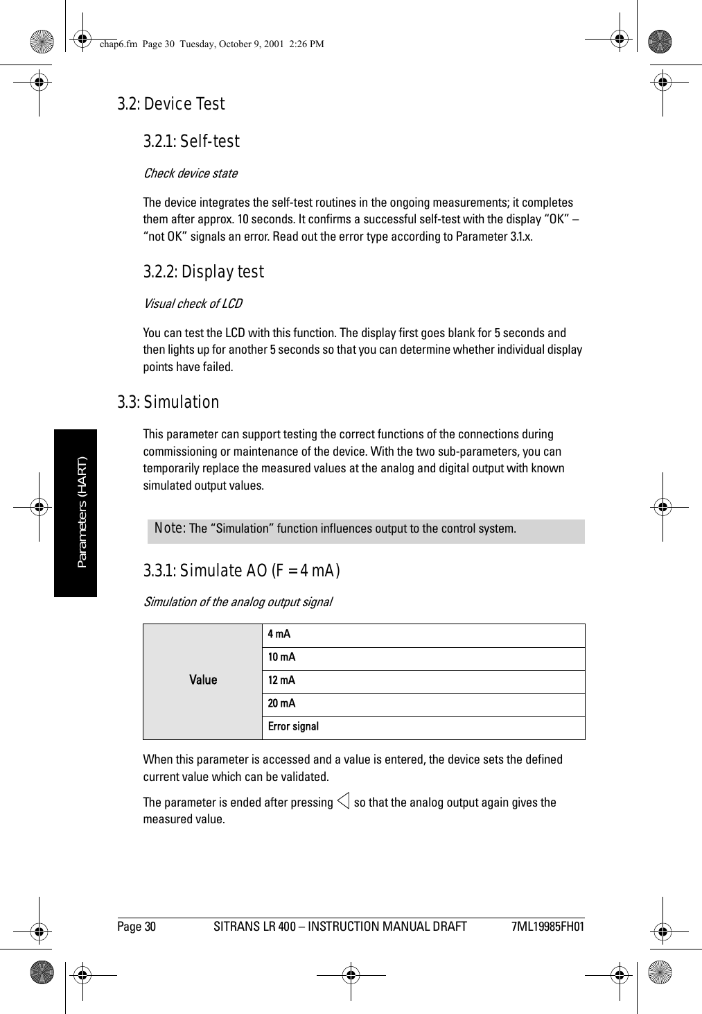
![7ML19985FH01 SITRANS LR 400 – INSTRUCTION MANUAL DRAFT Page 27mmmmmParameters (HART)Level damping (F = 1 s)Damping of level in sSet the damping of the level value in seconds. It acts on the analog output, the limit value monitor and the local display. For damping of the sensor signal, set Function 4.2.3:.Application Type (F - Liquid [store])Use of the vesselSelect Silo1 (solids) for tall, narrow silos. Select Silo 2 (solids) for large diameter silos typcially used for cement. In most cases you set one of the pre-specified applications here. The user vessels may adopt configurations which deviate from the factory settings. These are designed for special applications loaded at the factory or by service. the following parameters cannot be accessed when you set a user vessel: Parameter 4.2.2.2, Parameter 4.2.2.5, Parameter 4.2.2.6, Parameter 4.2.3.1 and Parameter 4.2.3.5Additional Parameters2. Display2.1: Multi-display (F = level in mSignal to noise ratio in db)Display of two measured values. Values determined in Parameter 4.5.1.1 (Line 1 Local) and in Parameter 4.5.1.4 (Line 2 Local).2.2: Level (F = m)Current level of measured medium (set unit using Length Unit in Auto-Setup).2.3: Volume (F = m3)Volume of measured medium (set unit using Parameter 4.1.2: Volume Unit).Value numerical valueValueLiquid (store)Liquid (process)Silo1 (solids)Silo2 (solids)User tank1User tank2chap6.fm Page 27 Tuesday, October 9, 2001 2:26 PM](https://usermanual.wiki/Siemens-Canada-Siemens-Milltronics-Process-Instruments/LR400.users-manual-1/User-Guide-174191-Page-31.png)
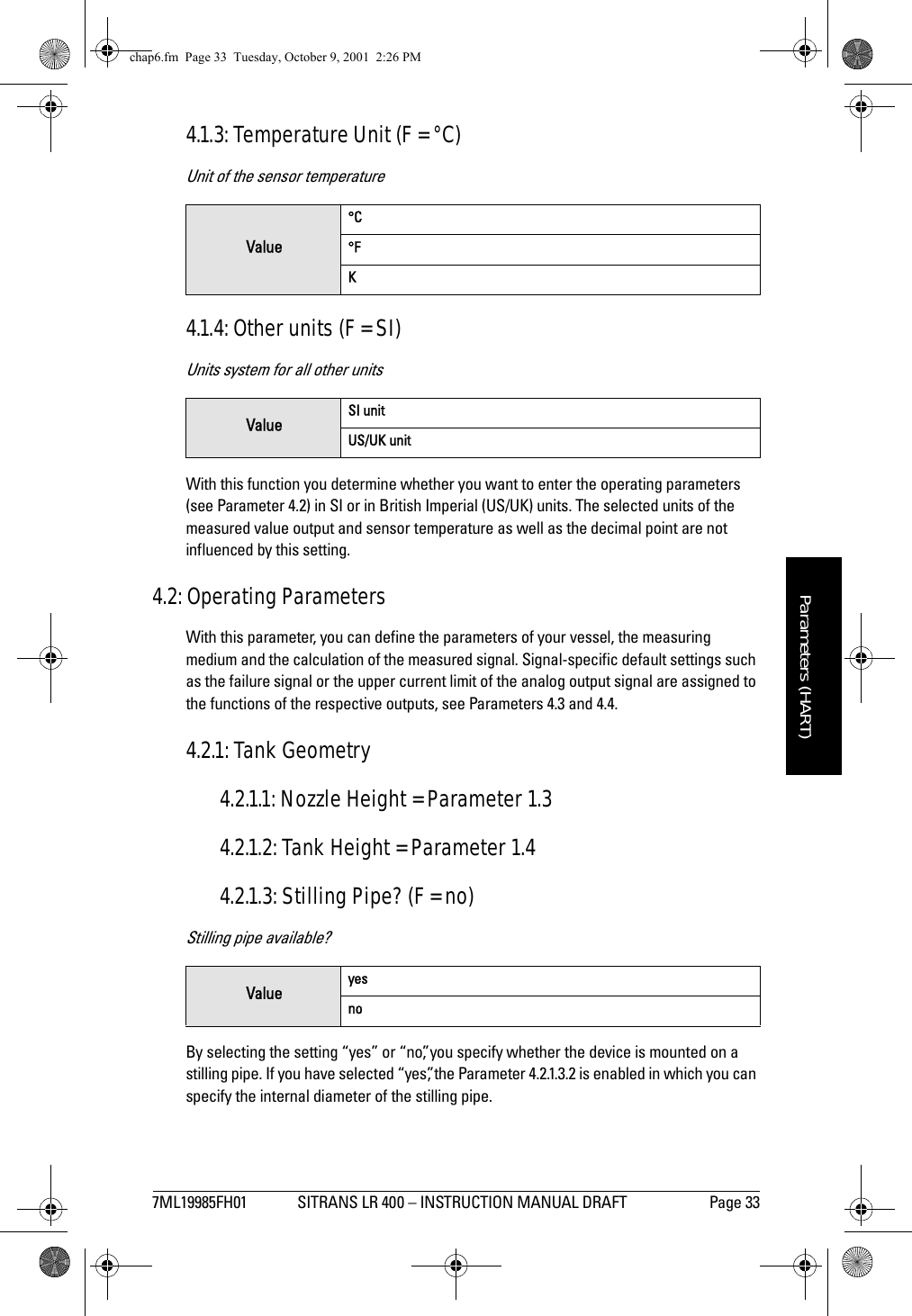
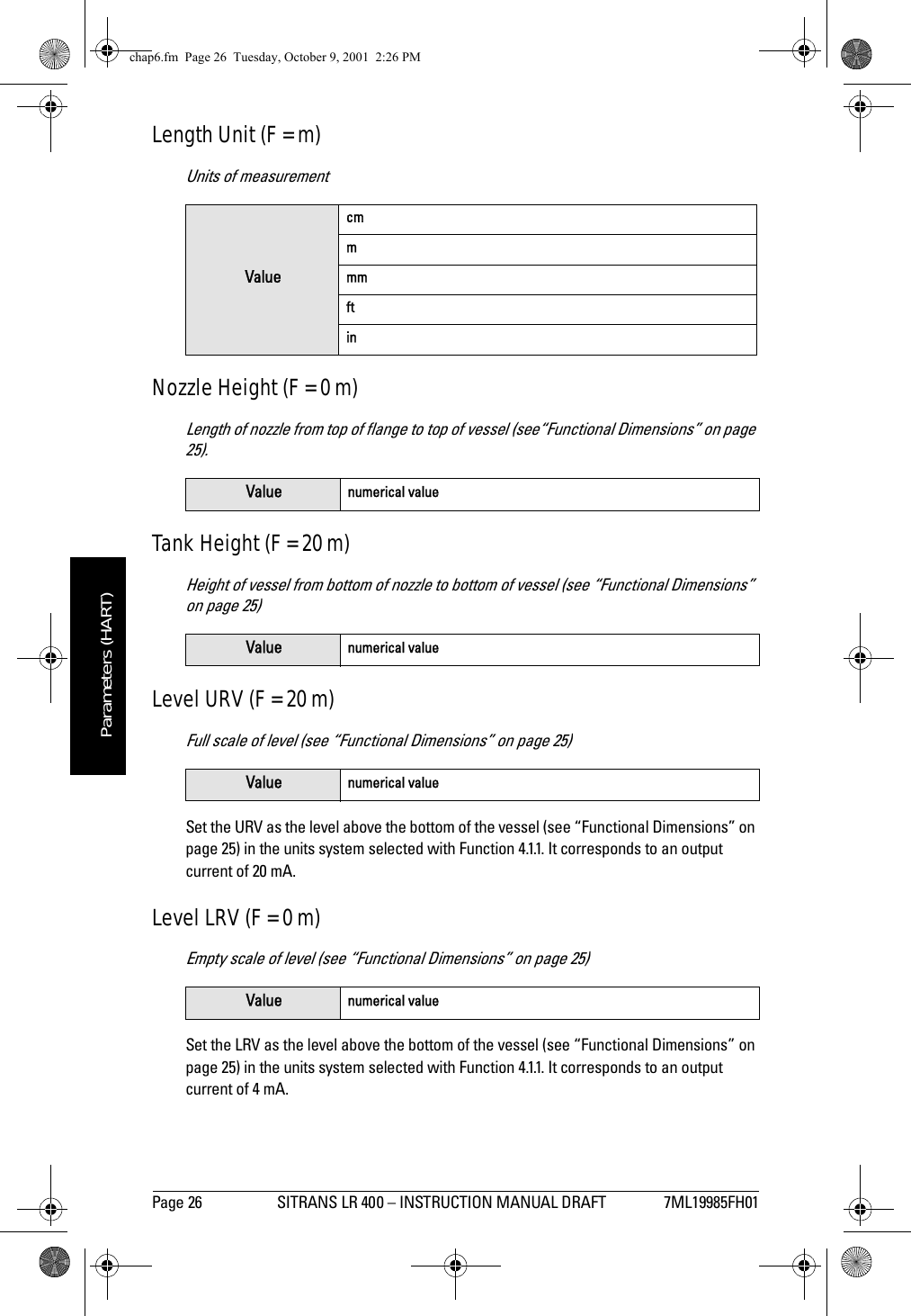
![Page 34 SITRANS LR 400 – INSTRUCTION MANUAL DRAFT 7ML19985FH01mmmmmParameters (HART)4.2.1.3: Pipe Diameter (F = 100 mm)Internal diameter of the stilling pipe4.2.2: Measuring Conditions4.2.2.1: Application Type (F - Liquid [store])Use of the vesselSelect Silo1 (solids) for tall, narrow silos. Select Silo 2 (solids) for large diameter silos typically used for cement. In most cases you set one of the pre-specified applications here. The user vessels may adopt configurations which deviate from the factory settings. These are designed for special applications loaded at the factory or by service. the following Parameters cannot be accessed when you set a user vessel: Parameter 4.2.2.2, Parameter 4.2.2.5, Parameter 4.2.2.6, Parameter 4.2.3.1 and Parameter 4.2.3.5.4.2.2.2: Surface (F = wavy)Surface structure of the measuring medium. Not displayed if a user vessel is selected in Parameter 4.2.2.1.This parameter is not displayed when a user vessel is selected in Parameter 4.2.2.1. In the case of poorly reflecting measuring media, you may be able to improve the measuring results by setting a different surface structure here. If your measuring medium forms waves more than 1 cm in height, you should select the “wavy” setting. The ”turbulent” setting is recommended for waves > 10 cm. The default setting is the “wavy” surface structure.Value numerical valueValueLiquid (store)Liquid (process)Silo1 (solids)Silo2 (solids)User tank1User tank2Valuesmoothwavyturbulentchap6.fm Page 34 Tuesday, October 9, 2001 2:26 PM](https://usermanual.wiki/Siemens-Canada-Siemens-Milltronics-Process-Instruments/LR400.users-manual-1/User-Guide-174191-Page-38.png)