Siemens Canada Siemens Milltronics Process Instruments LR400 SITRANS LR 400 User Manual sitranslrd3
Siemens Canada Ltd. - Siemens Milltronics Process Instruments SITRANS LR 400 sitranslrd3
Contents
- 1. users manual 1
- 2. users manual 2
- 3. users manual 3
users manual 1

Instruction Manual September 2001
SITRANS LR 400
SITRANS LR 400

© Siemens Milltronics Process Instruments Inc. 2001
Safety Guidelines
Warning notices must be observed to ensure personal safety as well as that of others, and to
protect the product and the connected equipment. These warning notices are accompanied
by a clarification of the level of caution to be observed.
Qualified Personnel
This device/system may only be set up and operated in conjunction with this manual.
Qualified personnel are only authorized to install and operate this equipment in accordance
with established safety practices and standards.
Warning: This product can only function properly and safely if it is correctly transported,
stored, installed, set up, operated, and maintained.
Note: Always use product in accordance with specifications.
Copyright Siemens Milltronics Process
Instruments Inc. 2001. All Rights ReservedDisclaimer of Liability
This document is available in bound version and in
electronic version. We encourage users to
purchase authorized bound manuals, or to view
electronic versions as designed and authored by
Siemens Milltronics Process Instruments Inc.
Siemens Milltronics Process Instruments Inc. will
not be responsible for the contents of partial or
whole reproductions of either bound or electronic
versions.
While we have verified the contents of
this manual for agreement with the
instrumentation described, variations
remain possible. Thus we cannot
guarantee full agreement. The
contents of this manual are regularly
reviewed and corrections are included
in subsequent editions. We welcome
all suggestions for improvement.
Technical data subject to change.
Contact Technical Publications at the following address:
Technical Publications
Siemens Milltronics Process Instruments Inc.
1954 Technology Drive, P.O. Box 4225
Peterborough, Ontario, Canada, K9J 7B1
Email: techpubs@siemens-milltronics.com
For the library of SMPI instruction manuals, visit: www.siemens-milltronics.com

7ML19985FH01 SITRANS LR 400 – INSTRUCTION MANUAL DRAFT i
mmmmm
Table of Conetns
Table of Contents
General Information ...........................................................................................................1
The Manual ...............................................................................................................................................1
SITRANS LR 400 ......................................................................................................................................3
Structure ....................................................................................................................................................3
Specifications ......................................................................................................................4
SITRANS LR 400 ......................................................................................................................................4
Dimensions ...............................................................................................................................................8
Installation .........................................................................................................................11
Mounting Location ................................................................................................................................11
Electrical connection ............................................................................................................................13
Start Up ...............................................................................................................................15
Self-test ....................................................................................................................................................15
Multi-display ...........................................................................................................................................15
Local Programming ...............................................................................................................................15
Auto-Setup ..............................................................................................................................................15
Operation ............................................................................................................................16
General information ..............................................................................................................................16
Measuring principle .............................................................................................................................16
Operating the SITRANS LR 400 .........................................................................................................19
Changing a Parameter Value ..............................................................................................................20
Disabling and enabling programming ..............................................................................................22
Operating examples ..............................................................................................................................23
Parameters (HART) ...........................................................................................................25
Required Parameters ............................................................................................................................25
Additional Parameters .........................................................................................................................27
Parameters (Profibus PA) ................................................................................................53
Troubleshooting .................................................................................................................62
Classification of faults ..........................................................................................................................62
Self-test ....................................................................................................................................................62
Symptoms, causes and their remedy ...............................................................................................63
Fault messages ......................................................................................................................................64
Maintenance and repairs ................................................................................................65
Changing the device fuse ....................................................................................................................65
Disconnecting the electronics part from the mechanical part ..................................................66
Cleaning the antenna ...........................................................................................................................66
Certificates .........................................................................................................................67
sitranslrd3.book Page i Tuesday, October 9, 2001 10:09 AM

ii SITRANS LR 400 – INSTRUCTION MANUAL DRAFT 7ML19985FH01
mmmmm
Table of Contents
Glossary ..............................................................................................................................68
Appendix I ..........................................................................................................................69
Alphabetical Parameter List ...............................................................................................................69
Appendix II .........................................................................................................................73
Programming Chart ...............................................................................................................................73
76
Appendix III ........................................................................................................................77
Ambient/Operating Temperature Specification .............................................................................77
Appendix IV ........................................................................................................................78
Process Pressure/Temperature de-Rating ......................................................................................78
sitranslrd3.book Page ii Tuesday, October 9, 2001 10:09 AM

7ML19985FH01 SITRANS LR 400 – INSTRUCTION MANUAL DRAFT Page 1
mmmmm
General Information
General Information
The Manual
Refer to this manual for proper installation, operation and maintenance of the SITRANS
LR 400 Radar Level Instrument.
Special attention must be paid to warnings and notices that are highlighted from the rest
of the text by grey boxes.
• These instructions do not claim to cover all details or variations in equipment, not to
provide for every possible contingency that may arise during installation, operation,
or maintenance.
• For further information or to resolve issues not covered in the manual, consult your
Siemens Milltronics representative.
• The contents of the manual shall not become part of or modify any prior or existing
agreement, commitment or relationship. The Sales Contract contains the entire
obligation of Siemens. The warranty contained in the contract between the parties
is the sole warranty of Siemens Milltronics.
Warning means that failure to observe the necessary precautions can result in death,
serious injury and/or considerable material damage.
Note means important information about the actual product or that part of the
operating manual to which particular attention should be paid.
Note: This equipment has been tested and found to comply with the limits for a Class
A digital device, pursuant to Part 15 of the FCC Rules. These limits are designed to
provide reasonable protection against harmful interference when the equipment is
operated in a commercial environment. This equipment generates, uses, and can
radiate radio frequency energy and, if not installed and used in accordance with the
instruction manual, may cause harmful interference to radio communications.
Operation of this equipment in a residential area is likely to cause harmful interference
in which case the user will be required to correct the interference at his own expense.
WARNING: Changes or modifications not expressly approved by Siemens Milltronics
could void the user’s authority to operate the equipment.
IMPORTANT: All specifications are subject to change without notice.
Please ensure that any safety-related information is confirmed with a
qualified Siemens Milltronics representative.

Page 2 SITRANS LR 400 –INSTRUCTION MANUAL DRAFT 7ML19985FH01
mmmmm
General Information
Qualified personnel
Qualified personnel are familiar with the installation, commissioning, and operation of
this equipment. In addition the person must be:
• trained and authorized to operate and service equipment/systems in accordance
with established safety procedures relating to electrical circuits, high pressures and
aggressive media.
• trained in the proper care and use of protective equipment in accordance with
established safety practices.
• trained in rendering first aid.
Warning:
• Installation shall only be performed by qualified personnel and in
accordance with local governing regulations
• The SITRANS LR 400 is to be used only in the manner outlined in this manual
or protection provided by equipment may be impaired.
7ML19985FH01 SITRANS LR 400 – INSTRUCTION MANUAL DRAFT Page 3
mmmmm
General Information
SITRANS LR 400
The SITRANS LR 400 Radar Level Instrument is designed for level measuring of liquids and
solids in storage vessels. SITRANS LR 400 operates reliably with its high microwave
frequency even with poorly reflecting measuring media. The narrow antenna beam results
in a sharp radiation cone, therefore SITRANS LR 400 is quite insensitive to vessel
interferences.
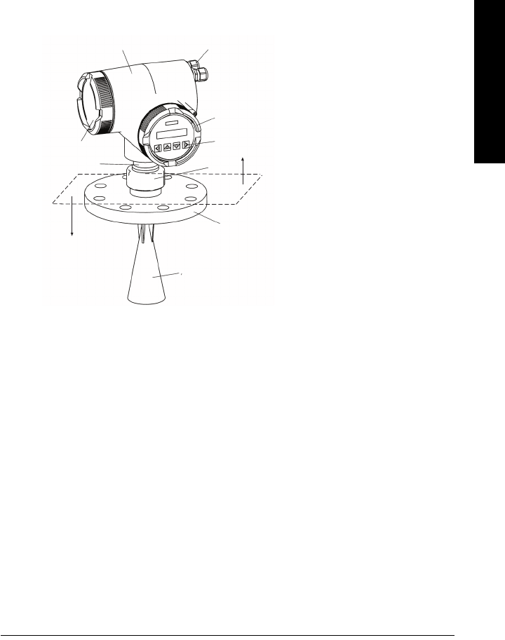
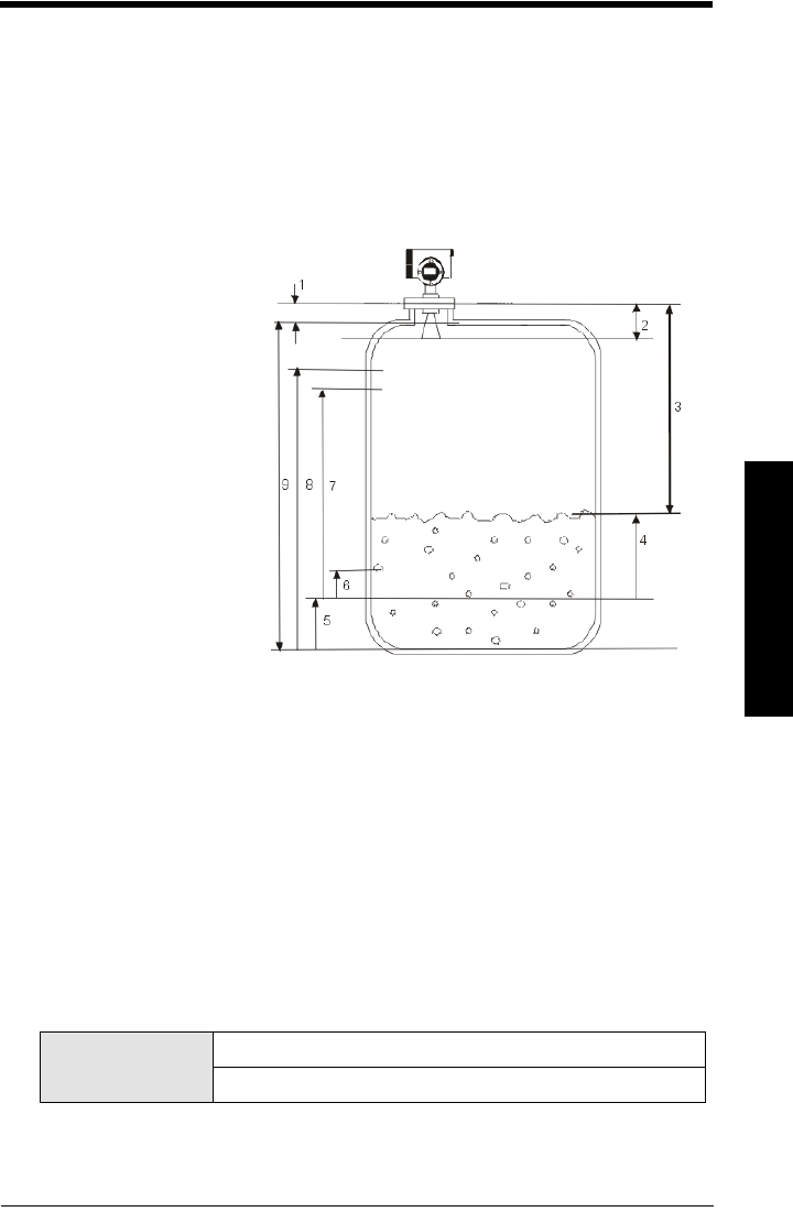
Structure
The terminals for the power cable and the signal cable are behind the connection cover
(9) on the left hand side of the housing (1). The signal cable must be fed in from the right
through the cable glands (2).
The device can be separated into electronic and mechanical sections at the threaded
ring (5).
An optional temperature extension is positioned between the threaded ring (5) and the
flange (6). Refer to Dimension diagram on page 8.
The end of the antenna (7) must reach inside the vessel through the vessel nozzle (see
page 12).
Return the orientation of the housing to the same position with reference to the flange
after any servicing to ensure similar performance.
12
3
4
5
6
7
8
9Electronics section
Mechanical section
1 Housing
2 Cable gland
3 Electronics cover
4 Operating and
monitoring module
5 Threaded ring
6 Process Flange
7 Antenna
8 Intermediate flange
9 Connection cover

Page 4 SITRANS LR 400 – INSTRUCTION MANUAL DRAFT 7ML19985FH01
mmmmm
Specifications
Specifications
SITRANS LR 400
Power
• Power Supply 120 to 230 Vac, ±15%, 50/60 Hz, 6W (12VA)
or
24 Vdc, +25/-20%, 6W
Power failure: bridge of at least 1 mains period (> 20 ms)
Fuse
• Fuse (both ac and dc versions)
SI1 Fast acting ceramic, 4 x 20 mm, 1A, 250 Vac
SI2 Slow-Blow, 4 x 20 mm, 0.63 A, 250 Vac
Interface
• Analog output (Not applicable to Profibus PA option)
Signal range 4 to 20 mA
Upper Limit 20 to 22.5 mA adjustable
Fail signal 3.6 mA; 22 mA; 24 mA or last value
Load Max. 600 Ω, for HART communication min. 230 Ω
• Digital Output
Function Configurable as a device status or limit value
(level, volume)
Signal type Relay, either NCC or NOC function
max. DC 50 V, max. 200 mA, rating max. 5 W.
Self-resetting fuse, Ri = 9 Ω
• Electrical Isolation Outputs electrically isolated from the power supply and
from each other
• Display LCD, two lines of 16 characters each,
configurable for the following displays:
level, volume, amplitude, digital output,
temperature, validity, signal-to-noise ratio
Multi–display: 2 freely selectable measured values are
displayed simultaneously
•Operation4 optical control elements, finger activated, menu-guided
Note: Siemens Milltronics makes every attempt to ensure the accuracy of these
specifications, but reserves the right to change them at any time. Please ensure these
are the most recent specifications. Contact your representative, or check our website
at www. milltronics.com for the most up-to-date information.
sitranslrd3.book Page 4 Tuesday, October 9, 2001 10:09 AM

7ML19985FH01 SITRANS LR 400 – INSTRUCTION MANUAL DRAFT Page 5
mmmmm
Specifications
Mechanical
• Nominal sizes DIN DN 80 DN 100 DN 150
ANSI 3" 4" 6"
JIS 80 mm 100 mm 150 mm
• Pressure classes
DIN PN16 PN40
ANSI 150 lb 300lb
JIS 10K
Flange
• Process Connection Flange DIN 2527, ANSI B16.5, or JIS B2238 equivalent bolt
pattern
• Materials of the wetted Stainless steel, material–no. 1.4571 and 1.4581, PTFE
parts –in contact with (or glass/PTFE, Zone 0 and Zone 20 devices)
the process
Enclosure
• construction Die-cast aluminum, painted
• conduit M20 (cable diameter 6 to 9.5 mm[0.24 to 0.37"])
or ½”-14 NPT
• ingress protection Type 4X/NEMA 4X, Type 6/NEMA 6, IP 671
Weight
• Weight of unit and flange
1.Use only approved, suitable sized hubs for watertight applications.
Flange Pressure Class Size Weight
DIN 2527 PN 16 DN 80 11.9 kg (26.1 lbs)
DN 100 13.2 kg (28.9 lbs)
DN 150 19.2 kg (42.1 lbs)
PN 40 DN 80 12.9 kg (28.4 lbs)
DN 100 15.5 kg (34.1 lbs)
DN 150 24.1 kg (43.1 lbs)
ANSI B 16.5 150 lb 3" 12.2 kg (26.8 lbs)
4" 14.8 kg (32.5 lbs)
6" 20.1 kg (44.2 lbs)
300 lb 3" 14.3 kg (31.5 lbs)
4" 20.2 kg (44.4 lbs)
6" 31.8 kg (69.9 lbs)
JIS B2238 10K 80 mm 11.9 kg (26.1 lbs)
100 mm 13.2 kg (28.9 lbs)
150 mm 19.2 kg (42.1 lbs)
sitranslrd3.book Page 5 Tuesday, October 9, 2001 10:09 AM

Page 6 SITRANS LR 400 – INSTRUCTION MANUAL DRAFT 7ML19985FH01
mmmmm
Specifications
Environmental
location: indoor/outdoor
altitude: 2000 m max
ambient temperature: -40 to 65°C (-40 to 149°F)
relative humidity: suitable for outdoor (Type / Nema 4X, 6/ IP67)
installation category II
pollution degree 4
• *Process Temperature -40 to 140°C (-40 to 284°F),optional -40 to 240°C
(-40 to 482°F)
• Electromagnetic compatibility
Spurious emission according to EN 50 081
Interference strength according to EN 50 082 and NAMUR
• *Perm. ambient -40 to 65°C (-40 to 149°F) (non-hazardous version)
temperature -20 to 65°C (-4 to 149°F) (hazardous version)
LCD: -10 to 55 °C (14 to 131°F)
Observe the temperature classes in hazardous areas!
• Perm. storage -30 to 80°C (-22 to 176°F),
temperature
Approvals (verify against device nameplate)
• Explosion Protection Certificate No. PTB 00 ATEX 1024
** Refer to device II 1/2G EEx d IIC T6II 2G EEx d IIC T6
nameplate II 1/2G EEx dem IIC T6II 2G EEx dem IIC T6
II 1/2G EEx dem [ib] IIC T6II 2G EEx dem [ib] IIC T6
II 1/2G EEx dem [ia] IIC T6II 2G EEx dem [ia] IIC T6
Certificate No. DMT 01 ATEX E 038
II 1/2 D IP 65 (dust zone 20, zone 21 approval)
• General FM, CSA
approval pending
• Radio FCC, Industry Canada, European Radio
approval pending
Comunication
• Communication:HART
Load 230 to 600 Ω, 230 to 500 Ω when connecting a coupling
module
Line two-wire shielded: ≤ 3 km
multi-wire shielded: ≤ 1.5 km
Protocol HART, Version 5.1
*Note: Refer to Process/Ambient de-rating curves in Appendix III.
sitranslrd3.book Page 6 Tuesday, October 9, 2001 10:09 AM

7ML19985FH01 SITRANS LR 400 – INSTRUCTION MANUAL DRAFT Page 7
mmmmm
Specifications
Communication: Profibus PA
Protocol Layer 1 and 2 Profibus PA,
technology: IEC 61158-2, slave-functionality
Device Class B
Device Profile 3.0
• PC/Laptop requirements IBM-compatible
RAM ≥ 64 Mbytes
Hard disk ≥ 100 Mbytes
RS 232-C interface
VGA graphic card (≥ 640 x 480)
• Software for PC/Laptop Windows 95/98 or NT 4.0
SIMATIC PDM
Performance
Measured value error (under reference conditions)
• Measuring error ≤ ± 15 mm at 0.26 to 2 m distance
≤ ± 5 mm at 2 to 10 m distance
≤ ± 15 mm at 10 to 45 m distance
(see diagram below)
• Dead zone 0-26 cm from bottom edge of flange
• Additional contribution of ≤ 0.1 % of the measured value
Analog Output ≤ 0.05 % of full scale
• Additional Contribution of ≤ 0.05 % per 10 % deviation of UN
the Supply Voltage
• Influence of pressure ≤ 0.3 % to 10 bar without pressure correction
(air, 20°C) ≤ 2 % at 10 to 64 bar without pressure correction
• Long-term stability ≤ ± 1 mm/year
• Repetitive accuracy ≤ ± 1 mm at 0 to 45 m, damping ≥ 1 s
• Reference conditions
Medium Triple reflector on the main axis of the antenna main lobe
Ambient temperature 25 ± 5°C (77 ± 9°F)
Ambient pressure 1050 mbar ± 10 %
Absolute Measuring Error
5
10
15
20
Absolute measuring error [mm]
10 20 30 40
Distance from flange [m]
452
-20
-15
-10
-5
0
sitranslrd3.book Page 7 Tuesday, October 9, 2001 10:09 AM
Page 8 SITRANS LR 400 – INSTRUCTION MANUAL DRAFT 7ML19985FH01
mmmmm
Specifications
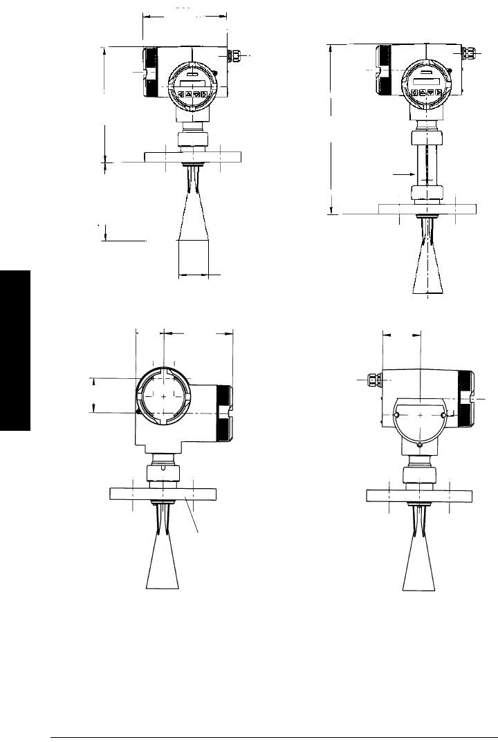
Dimensions
Flange acc. to DIN 2527 / ANSI B
16.5 / JIS B 2238 bolt hole pattern
optional
temperature
extension
409 mm
(16.1")
281 mm
(11.1")
191 mm
(7.5") or
238 mm
(9.4")
72 mm (2.8") or
98 mm (3.9")
153 mm
(6.0")
62 mm
(2.4")
73 mm
(2.9")
84 mm
(3.3")
204 mm
(8.0")
Customer to provide adequate bolting and gasket to
retain vessel pressure and provide sufficient seating.
sitranslrd3.book Page 8 Tuesday, October 9, 2001 10:09 AM
7ML19985FH01 SITRANS LR 400 – INSTRUCTION MANUAL DRAFT Page 9
mmmmm
Specifications
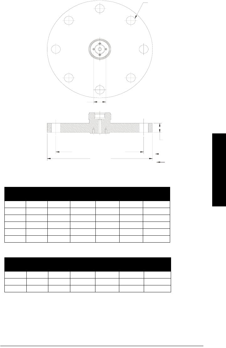
DIN / JIS Flat Face Flange Diagram
Flange according to DIN 2527 (see Flange Diagram on page 9)
Flange according to JIS B 2238
Pipe
Size Flange
Size Flange
O.D. Thickness
(s) Bolt Hole
Circle Ø Bolt Hole
ØNumber of
Bolts
80 mm PN 16 200 mm 20.0 mm 160 mm 18.0 mm 8
100 mm PN16 220 mm 20.0 mm 180 mm 18.0 mm 8
150 mm PN 16 285 mm 22.0 mm 240 mm 22.0 mm 8
80 mm PN 40 200 mm 24.0 mm 160 mm 18.0 mm 8
100 mm PN 40 230 mm 24.0 mm 190 mm 22.0 mm 8
150 mm PN 40 300 mm 28.0 mm 250 mm 26.0 mm 8
Pipe
Size Flange
Size Flange
O.D. Thickness
(s) Bolt Hole
Circle Ø Bolt Hole
ØNumber of
Bolts
80 mm 10 K 185 mm 20.0 mm 150 mm 19.0 mm 8
100 mm 10 K 210 mm 22.0 mm 175 mm 19.0 mm 8
150 mm 10 k 280 mm 24.0 mm 240 mm 23.0 mm 8
Bolt Hole Ø
Thickness (s)
Flange O.D.
Bolt Hole Circle Ø
horn mounting holes
sitranslrd3.book Page 9 Tuesday, October 9, 2001 10:09 AM
Page 10 SITRANS LR 400 – INSTRUCTION MANUAL DRAFT 7ML19985FH01
mmmmm
Specifications
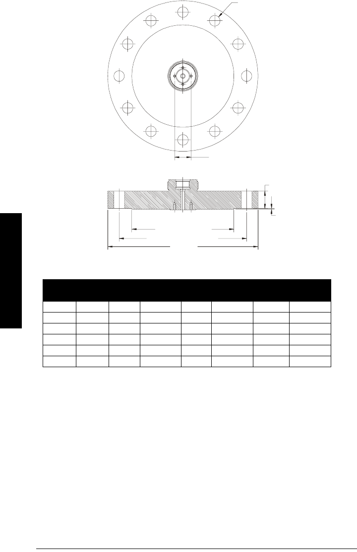
ANSI Raised Face Flange Diagram
Flange according to ANSI B 16.5 (see Flange Diagram on page 9)
Pipe
Size Flange
Size Flange
O.D. Thickness
(s) Face
O.D. Bolt Hole
Circle Ø Bolt Hole
ØNumber of
Bolts
3" 150 # 7.50" 0.941" 5.0" 6.00" 0.74" 4
4" 150 # 9.00" 0.941" 6.19" 7.50" 075" 8
6" 150 # 11.00" 1.00" 8.5" 6.62" 0.88" 8
3" 300 # 8.25" 1.12" 5.0" 6.62 0.88" 8
4" 300 # 10.00" 1.25" 6.19" 7.88" 0.88" 8
6" 300 # 12.51" 1.44" 8.5" 10.62" 0.88" 12
Thickness (s)
Raised Face thickness
0.063" (mm)
Bolt Hole Ø
horn mounting holes
Flange O.D.
Bolt Hole Circle Ø
Face O.D.
sitranslrd3.book Page 10 Tuesday, October 9, 2001 10:09 AM
7ML19985FH01 SITRANS LR 400 – INSTRUCTION MANUAL DRAFT Page 11
mmmmm
Installation
Installation
Mounting Location
• Do not mount in direct sunlight without the use of a sun shield. Refer to Appendix III
(Ambient/Operating Temperature Specfication) on page 77.
Note:
• The SITRANS LR 400 is rated for Type 4X/NEMA 4X, Type 6/NEMA 6, IP 67.
Follow all installation and operating instructions to meet the requirements
of this type of protection. Use only approved, suitable sized hubs for
watertight applications.
• Observe all maximum permissible ambient and process temperatures.
Refer to Appendix III (Ambient/Operating Temperature Specification).
• Provide a warning sign and/or touch guard if the surface of the measuring
instrument can get hotter than 70°C in use.
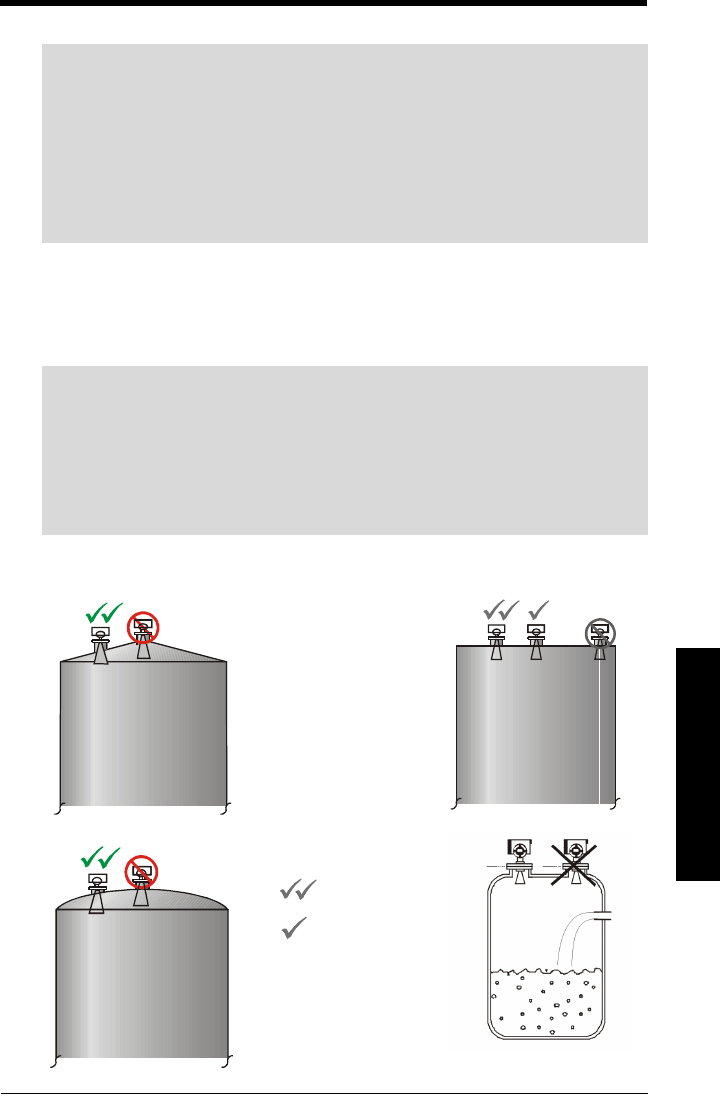
Warning: For vessels with conical or parbolic tops, avoid mounting the
unit at the center. The concavity of the top can focus echoes into the centre,
giving false readings.
Mount the unit more than 1 m away from the vessel walls, pipes and other
assemblies as well as the filling stream because all these influences will become
noticeable as reflective interference. Align the antenna so that the radar cone hits
the surface of the measuring medium as vertically as possible
Flat
Coni cal
P a ra b o lic
Conical
Parabolic
Flat
is preferred
location
is acceptable
location
sitranslrd3.book Page 11 Tuesday, October 9, 2001 10:09 AM

Page 12 SITRANS LR 400 – INSTRUCTION MANUAL DRAFT 7ML19985FH01
mmmmm
Installation
Correct Installation in Mounting Nozzle
The bottom edge of the antenna must reach inside the vessel to avoid reflective
interference at the wall of the nozzle. Above flange size DN 150/6 inch, the antenna may
end in the nozzle unless the radiation cone (the extension of the antenna’s angle) touches
the nozzle wall.
sitranslrd3.book Page 12 Tuesday, October 9, 2001 10:09 AM
7ML19985FH01 SITRANS LR 400 – INSTRUCTION MANUAL DRAFT Page 13
mmmmm
Installation
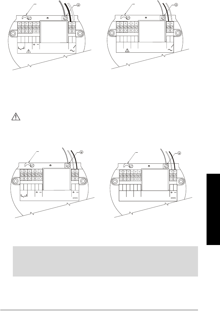
Electrical connection
AC version:
• The equipment must be protected by a 15A fuse or circuit breaker in the building
installation.
• A circuit breaker or switch in the building installation, marked as the disconnect
switch, shall be in close proximity to the equipment and within easy reach of the
operator.
All field wiring must have insulation suitable for at least 250 V.
DC version:
• DC input terminals shall be supplied from an SELV source in accordance with IEC
1010-1 Annex H.
1264 5
378
L
1
L
2
N
Rated temperature of
connection cables must
exceed maximum ambient
temperature by at least 15 K
PROFI-
BUS PA
Hart Wiring Profibus Wiring
1264 5
378
L
1
L
2
N
mA
Rated temperature of
connection cables must
exceed m aximum ambient
temperature by at least 15 K
earth terminal
earth
terminal
cable clamp cable clamp
1264 5
378
mA
19-3 0 V
Rated temperature of
connection cables must
exceed maximum ambient
temperature by at least 15 K
12645378
PROFI-
BUS PA
19- 30 V
Rated temperature of
connection cables must
exceed maximum ambient
temp erature by at leas t 15 K
Hart Wiring Profibus Wiring
earth terminal earth
terminal
cable clamp cable clamp
Note (AC and DC versions):
• 4-20 mA, Profibus PA, DC input circuits, 14 - 20 AWG, shielded copper wire
• AC input circuit, min 14 AWG copper wire
• Recommended torque on terminal clamping screws, 0.5 - 0.6 Nm
sitranslrd3.book Page 13 Tuesday, October 9, 2001 10:09 AM

Page 14 SITRANS LR 400 – INSTRUCTION MANUAL DRAFT 7ML19985FH01
mmmmm
Installation
Make the electrical connections as follows:
1. Release the cover lock on the connection box with a 3 mm Allen key.
2. Unscrew the cover from the connection box.
3. Push the power cable and signal cable through the cable gland on the right of the
unit., up to the terminal strip. Lay the cable in a bend before the cable gland so that
moisture cannot enter the connection box.
4. Connect the earth conductor of the power supply to the earth terminal in the
connection box. Choose a length of cable so that the earth conductor is
disconnected last when you pull the cable.
5. In devices with ignition protection types II 1/2G EEx dem [ia] IIC T6 and II 1/2G EEx
dem [ib] IIC T6 or II 2G EEx dem [ia] IIC T6 and II 2G EEx dem [ib] IIC T6, mount the
cover for the power supply terminals.
6. Tighten the cable screw gland and check the strain relief (pull and turn).
7. In devices with ignition protection type II 1/2G EEx D IIC T6 or II 2G EEx d IIC T6,
replace unused screw-type cable glands with a certified dummy plug.
8. Screw the cover onto the housing and tighten it without using a tool. The sealing
ring must be clean and undamaged.
9. Mount the cover lock of the connection box cover.
10. Connect the earth terminal located between the screw-type cable glands to a
ground connection at your vessel by using a cable of a cross-section at least
2.5 mm2 wide.
For error-free communication via the HART protocol, a load of at least 230 Ω must be
available in the signal circuit.
Warning: To avoid short-circuits, do not connect a load resistance with
bare wires in the connection box.
The housing cover may not be unscrewed in a hazardous area when the
device is under voltage (power supply, digital outputs on external
supply).
In devices with ignition protection types II 1/2G EEx dem [ia] IIC T6 and
II 1/2G EEx dem [ib] IIC T6 II 2G EEx dem [ia] IIC T6 and
II 2G EEx dem [ib] IIC T6, only the cover of the connection box may be
unscrewed for test purposes. The cover on the power supply terminals
may not be removed!
sitranslrd3.book Page 14 Tuesday, October 9, 2001 10:09 AM

7ML19985FH01 SITRANS LR 400 – INSTRUCTION MANUAL DRAFT Page 15
mmmmm
Start Up
Start Up
Self-test
The device performs a self-test after switching on the power supply. It is ready for
operation and programming when the LCD displays the multi-display and the control
elements can be operated.
Multi-display
The multi-display shows on the LCD after a successful self-test with the output of the
level in the first line and the signal-to-noise ratio in the second line (factory setting):
Local Programming
When the mult-display shows on the LCD, you are ready to begin local programming
using the optical control elements. To access the parameter settings, touch the
element once. "Main Menu" is displayed in the first line of the LCD. Then program the unit
beginning with the Auto-Setup parameters.
Auto-Setup
After switching on the SITRANS LR 400, and after a successful self test, set the Auto-
Setup parameters to make the system operational.: (see page 25).
• The language of the local user interface (English or Deutsch)
• The unit of length of the measured level
• The nozzle height in the selected unit of length
•The vessel height in the selected unit of length)
• The LRV as a distance from the bottom of the vessel
• The URV as a distance from the bottom of the vessel
• The damping of the measured level in s.
• The application type
• The bus-address by Profibus PA communication (on Profibus models)
Enter the necessary values as described in "Parmeters" on page 25.
If the multi-display does not appear or displays incorrect measured values after Auto-
Setup, proceed as described in “Troubleshooting” on page 62.
Refer to the Parameter section that begins on page 25 for a list of available parameters.
Note: Frequent switching off and on of the devices causes aging of the electronics
(see Parameter 3.1).
+1 2 30 0 m
bd03+
.
sitranslrd3.book Page 15 Tuesday, October 9, 2001 10:09 AM
Page 16 SITRANS LR 400 – INSTRUCTION MANUAL DRAFT 7ML19985FH01
mmmmm
Operation
Operation
General information
You can operate the SITRANS LR 400 with:
• Local operating and monitoring module
• HART-Communicator or Profibus PA
• PC/Laptop and SIMATIC PDM software (recommended)
Measuring principle
The SITRANS LR 400 operates according to the FMCW (Frequency Modulated Continuous
Wave) method. Its antenna sends microwaves to the surface of the measuring medium,
the frequency of which is modulated continuously (see “Determining the Differential
Frequency on page 17). A receiver registers the reflection at the surface of the measuring
medium and links it with the simultaneously radiated signal.
The propagation speed of microwaves in gases corresponds to the speed of light. The
distance
d
is therefore proportional to the propagation time
t
:
d= distance, t = measured time, c = speed of light
Note: The device can be operated and programmed most comfortably with the
SIMATIC PDM software. This software gives you the added possibility of saving and
archiving your application-specific parameters and copying them back into the device
if necessary.
It is best to perform the operations described in the following sections directly on the
device to familiarize yourself with the operation.
d
dct⋅
2
--------=
chap6.fm Page 16 Tuesday, October 9, 2001 2:26 PM
7ML19985FH01 SITRANS LR 400 – INSTRUCTION MANUAL DRAFT Page 17
mmmmm
Operation
Since the transmission signal has changed its frequency until the reception signal arrives,
the link gives a differential frequency
f
d
, which is proportional to the distance
d
from the
reflecting surface.
The distance
d
is given by the ratio of the differential frequency
f
d
to the frequency
deviation
B
and the duration of a frequency modulation phase
T
(see“Determining the
Differential Frequency” on page 17):
B = bandwidth (frequency deviation), d = distance, T = modulation duration,
c = speed of light
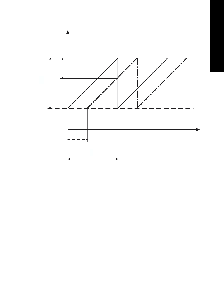
Determining the Differential Frequency
Example
The linear frequency deviation is 200 MHz at a modulation duration of 10 ms. The surface
of the measuring medium is 10 m away from the transmitting antenna. The difference
signal then has a frequency of:
Every reflection at a surface generates a different frequency. The reception signal
therefore consists of a frequency mix from which the disturbance frequencies must be
filtered which are caused by fixed targets such as struts inside the vessel.
fd
2Bd⋅⋅
Tc⋅
------------------ d,fdTc⋅⋅
2B
-------------------==
fd
time
Frequency
T
B
transmission
signal
reception
signal
t
fd
2210
810⋅⋅ ⋅
10 3– 310
8
⋅⋅
---------------------------------- 13 333kHz,==
chap6.fm Page 17 Tuesday, October 9, 2001 2:26 PM

Page 18 SITRANS LR 400 – INSTRUCTION MANUAL DRAFT 7ML19985FH01
mmmmm
Operation
The electrical connection of the PC/Laptops and the HART-Communicator to the 4-20-mA
signal cable is shown below.
Connection, HART Schematic Diagram
Connection, Profibus Schematic Diagram
Warning: The coupling module (shown below) may not be used in areas
where there is an explosion hazard and may not be connected to
intrinsically safe circuits.
chap6.fm Page 18 Tuesday, October 9, 2001 2:26 PM

7ML19985FH01 SITRANS LR 400 – INSTRUCTION MANUAL DRAFT Page 19
mmmmm
Operation
Operating the SITRANS LR 400
To access parameters, use the optical control elements on the operating and monitoring
module (shown below). Touch the glass in the appropriate place with your fingertips like
on a touch screen. The two-line LCD displays the parameters. You can alter the setting or
change to other parameters using the controls.
Operating and Monitoring Module
Selecting a Parameter
The first line of the display tells you the current operating level. The second line indicates
one of the parameters you can access under the parameter group. If the level offers more
than one parameter, you can have them displayed in cyclic order by using the control
elements (forwards) and (backwards). The control element accesss the
parameter currently displayed on the second line. The fourth control element, , closes
this parameter and moves up one level until you return to the multi-display.
When you select a parameter, the device displays the parameter's current value in the
second line. When the value flashes, the device programming is enabled (see “Disabling
and enabling programming” on page 22) and you can change the current setting. There
are two different ways of changing the settings, which are explained in the following
sections.
LCD
Two lines of 16 characters each
Optical control element
Note: The background illumination of the LCD switches on automatically as soon as
you use a control element. It goes out about three minutes after last use of a control
element.
chap6.fm Page 19 Tuesday, October 9, 2001 2:26 PM
Page 20 SITRANS LR 400 – INSTRUCTION MANUAL DRAFT 7ML19985FH01
mmmmm
Operation
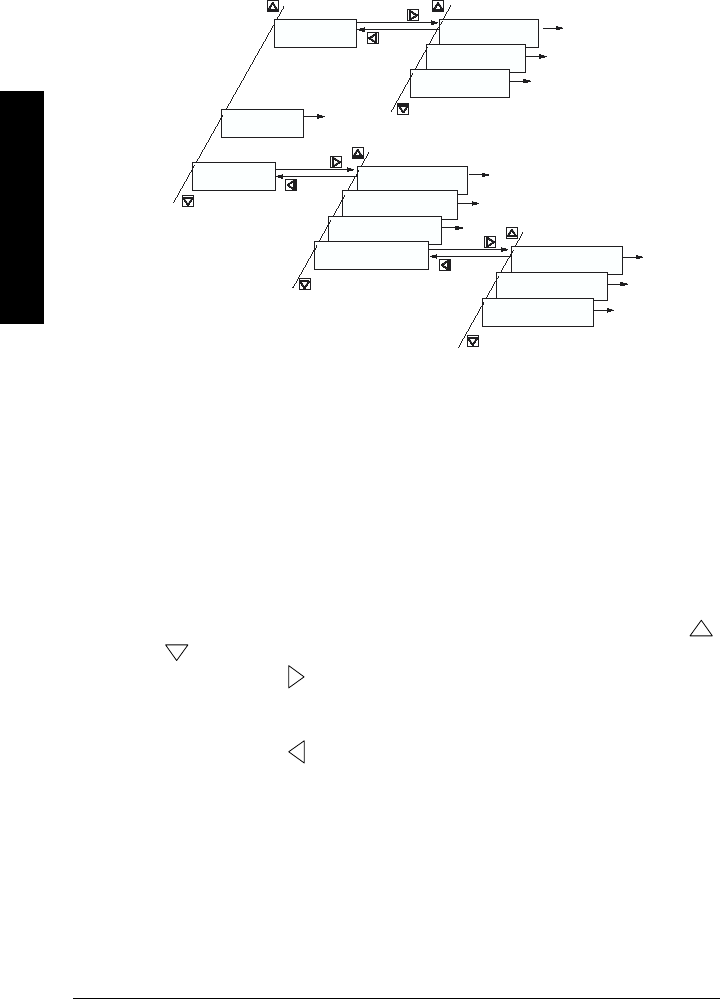
Structure of Parameters
Operation is hierarchically structured: The parameters are arranged in logical parameter
groups and assigned a numerical menu identification (see below).
Changing a Parameter Value
Entering Value from Selection List
In many cases, the device offers a number of entries in a selection list which you can
assign to a parameter. For these functions, you cannot enter anything other than a
selection from the displayed list.
You will see a single item of the selection list in the second line of the display.
• Change the display cyclically forwards or backwards with the control elements
or to select the desired entry from the list.
The control element operates like an “Enter” key: Use it to assign the displayed
list entry to the parameter. The device accepts the new setting, closes the input and
switches back to the next operating level up.
• The control element operates like a “Cancel” key: As soon as you press it, the
device closes the parameter input but retains the originally displayed value: It does
not save a changed setting!
For an example of assigning a value from a selection list, see “Operating examples” on
page 23.
Function group
2 Display
.
2. Display
1 Multi-display
2. Display
2 Level
2. Display
3 Volume
Function group
3 Diagnostics
Function group
4 Device data 4. Device Data
1 Units
4. Device Data
2 Operating parameters
4. Device Data
3 Analog output
4. Device Data
4 Digital output 4.4. Digital output
1 Function DO
4.4. Digital output
2 Signal type DO
4.4. Digital output
3 Level param.
Operating level 1
Operating level 2
Operating level 3
chap6.fm Page 20 Tuesday, October 9, 2001 2:26 PM

7ML19985FH01 SITRANS LR 400 – INSTRUCTION MANUAL DRAFT Page 21
mmmmm
Operation
Entering Manual Value
If the device allows manual input of the displayed parameter, the control elements
operate like a cursor control. The current input position is marked by flashing of a single
character.
• The control elements and change the character’s value by one up or
down. For numeric values the character changes to the next digit up or down, for
signs between + and -, and for text inputs to the next element of the ASCII character
set.
• Use the control element to move the input position to the right. At the extreme
right position, press again: Here the control element operates like an “Enter”
key. The device saves the changed value (if it is within the permissible input range –
otherwise an error message appears on the operating and monitoring module!) and
closes the parameter input.
• Use the control element to move the input position to the left. At the extreme left
position, press again: The control element now functions as a “Cancel” key. The
device close the parameter input without saving the changed value.
If you exceed the representable value range when entering a digit, SITRANS LR 400
automatically places the numeric value at the next highest position. For example, if you
see the numeric value “0.9” on the display and press the control element , the display
does not change to “0.0” but to “1.0”. Value “9” becomes “10”, value “90” or “99”, “100”
(depending on whether you have set the input position to the second or first “9”), etc. The
device adds further places before the decimal point automatically!
This input system also works in the opposite direction: If, for example, the value “100” is
displayed and you use the control element on the first or second “0”, the numeric
value changes to “90” or “99” and the device cancels the places in front of the decimal
point which are no longer required. Leading zeros are not displayed.
You can also set the cursor to the decimal point (unless an integer value is currently
being displayed). The control elements or then immediately multiply or divide
the displayed value by 10. The necessary additional places in front of the decimal point
appear. However, you cannot change the number of displayed decimal places; they
always remain the same.
Display text assigned to a parameter may sometimes be longer than the field of the
display. An arrow pointing outward on the right or left hand side of the display line
indicates that the text continues outside the display. You can move the text with the
control elements and by moving the pointer past the end of the line allowing you to
read the rest of the text.
An example of manual input of a value is described in “Operating examples” on page 23,
example 2.
chap6.fm Page 21 Tuesday, October 9, 2001 2:26 PM

Page 22 SITRANS LR 400 – INSTRUCTION MANUAL DRAFT 7ML19985FH01
mmmmm
Operation
Disabling and enabling programming
To prevent unauthorized personnel causing programming errors via the operating and
monitoring module, set a customer code – a personal, freely selectable code number
which may be up to 9 characters long. A device protected by a customer code still
displays all functions and values but it requests input of the code number before allowing
a parameter to be reset.
Programming is enabled when you:
• enter the requested customer code for the current parameter (only the current
parameter is enabled for reprogramming. All the others are still waiting for input of
the customer code).
• or release the programming lock for all parameters at once in the “Code Input”
function (see Parameter 5.1 on page 52).
Both ways will release the programming lock on parameters for approx. 10 min.
When you return to the multi-display or enter a number in the “Code Input” function
which is different to the customer code, or do not operate the device for 10 minutes, the
programming lock is enabled.
Enter the customer code as described in Parameter 5.2 on page 52.
Note: If the customer code is “0” in Parameter 5.2, programming of parameters is
always enabled.
chap6.fm Page 22 Tuesday, October 9, 2001 2:26 PM

7ML19985FH01 SITRANS LR 400 – INSTRUCTION MANUAL DRAFT Page 23
mmmmm
Operation
Operating examples
Example 1(HART)
The length unit should be changed from “m” to “mm.”. The starting point is the multi-
display.
Follow the path traced with a bold line in the diagram above for input. The other paths
lead to other device functions and parameters which are not required in this example.
Next to the operating path, the control elements which you need to press are indicated
and the operating steps are numbered.
2 x
5
6
Function group
4 Device data
4
Function group
3 Diagnostics
1
2
3
Function group
1 Auto-Setup
Function group
2 Display
+12,300 m
+30 dB
4. Device data
1 Units 4.1 Units
1 Length unit
67
8
4. Device data
2 Operating param.
4. Device data
3 Analog output 4.3 Analog output
1 AO select
4.3.1 AO select
Level
4.3 Analog output
2 Level param.
4.3.2 Level param.
1 Level URV
4.1.1 Length unit
m
4.1.1 Length unit
mm
Multi display
9
2 x
10
chap6.fm Page 23 Tuesday, October 9, 2001 2:26 PM
Page 24 SITRANS LR 400 – INSTRUCTION MANUAL DRAFT 7ML19985FH01
mmmmm
Operation
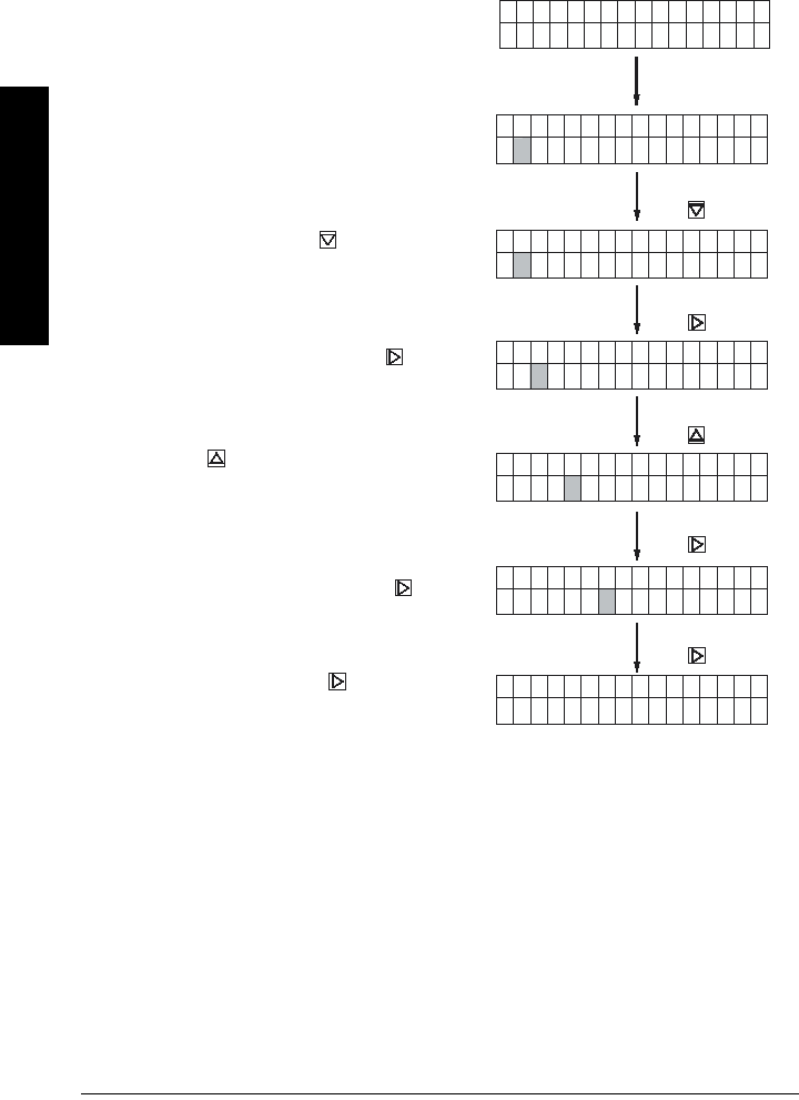
Example 2
The filling speed should be changed from 2.0 cm/min to 100 cm/min.
Access the “Fill speed” parameter from the multi-display according to instructions on
page page 19.
The default setting appears in the display
Enable the programming.
The second segment of the second display
line flashes.
Set the digit to 1 with the control element.
Select the decimal point with the control
element.
Press the control element twice so that
two other places appear in front of the decimal
point.
Select the last decimal place with
And end the input with the control element
(Enter function)
4.2.2.5. f i l l i n g s p e e
+ 2.0 0 c m / m i n
4.2.2.5. f i l l i n g s p e e
+ 2 , 0 0 c m / m i n
4.2.2.5. f i l l i n g s p e e
+ 1 , 0 0 c m / m i n
4.2.2.5. f i l l i n g s p e e
+ 1 , 0 0 c m / m i n
4.2.2.5. f i l l i n g s p e e
+ 1 0 0 , 0 0 c m / m i n
4.2.2.5. f i l l i n g s p e e
+ 1 0 0 , 0 0 c m / m i n
4.2.2 M e a s u r.c o n d i t
5 f i l l i n g s p e e d
1 x
1 x
2 x
2 x
1 x
chap6.fm Page 24 Tuesday, October 9, 2001 2:26 PM
7ML19985FH01 SITRANS LR 400 – INSTRUCTION MANUAL DRAFT Page 25
mmmmm
Parameters (HART)
Parameters (HART)
The parameter groups are followed by the parameters within each group. The parameter
tables show the values you need to enter in bold type, followed by additional information
when necessary. Factory settings are displayed after the parameter name, where
applicable.
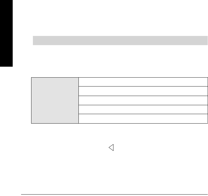
Functional Dimensions
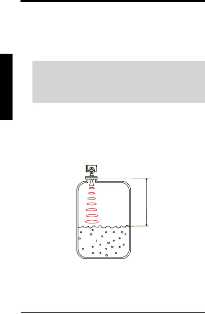
Required Parameters
The following parameters are absolutely essential for proper operation of the device.
They apply to all applications and are required to make the system operational.
1. Auto-Setup
Language Local (F = English)
Language of the local user interface
Value English
Deustch
1 Nozzle height
2 Dead band
3 Raw value
(measured)
4 Level (= calculated
value)
5 Lower range value
6 Lower limit
7 Upper limit
8 Upper range value
9 vessel height
chap6.fm Page 25 Tuesday, October 9, 2001 2:26 PM

Page 26 SITRANS LR 400 – INSTRUCTION MANUAL DRAFT 7ML19985FH01
mmmmm
Parameters (HART)
Length Unit (F = m)
Units of measurement
Nozzle Height (F = 0 m)
Length of nozzle from top of flange to top of vessel (see“Functional Dimensions” on page
25).
Tank Height (F = 20 m)
Height of vessel from bottom of nozzle to bottom of vessel (see “Functional Dimensions”
on page 25)
Level URV (F = 20 m)
Full scale of level (see “Functional Dimensions” on page 25)
Set the URV as the level above the bottom of the vessel (see “Functional Dimensions” on
page 25) in the units system selected with Function 4.1.1. It corresponds to an output
current of 20 mA.
Level LRV (F = 0 m)
Empty scale of level (see “Functional Dimensions” on page 25)
Set the LRV as the level above the bottom of the vessel (see “Functional Dimensions” on
page 25) in the units system selected with Function 4.1.1. It corresponds to an output
current of 4 mA.
Value
cm
m
mm
ft
in
Value numerical value
Value numerical value
Value numerical value
Value numerical value
chap6.fm Page 26 Tuesday, October 9, 2001 2:26 PM

7ML19985FH01 SITRANS LR 400 – INSTRUCTION MANUAL DRAFT Page 27
mmmmm
Parameters (HART)
Level damping (F = 1 s)
Damping of level in s
Set the damping of the level value in seconds. It acts on the analog output, the limit value
monitor and the local display. For damping of the sensor signal, set Function 4.2.3:.
Application Type (F - Liquid [store])
Use of the vessel
Select Silo1 (solids) for tall, narrow silos. Select Silo 2 (solids) for large diameter silos typcially
used for cement. In most cases you set one of the pre-specified applications here. The user
vessels may adopt configurations which deviate from the factory settings. These are designed
for special applications loaded at the factory or by service. the following parameters cannot be
accessed when you set a user vessel: Parameter 4.2.2.2, Parameter 4.2.2.5, Parameter 4.2.2.6,
Parameter 4.2.3.1 and Parameter 4.2.3.5
Additional Parameters
2. Display
2.1: Multi-display (F = level in m
Signal to noise ratio in db)
Display of two measured values. Values determined in Parameter 4.5.1.1 (Line 1 Local) and
in Parameter 4.5.1.4 (Line 2 Local).
2.2: Level (F = m)
Current level of measured medium (set unit using Length Unit in Auto-Setup).
2.3: Volume (F = m3)
Volume of measured medium (set unit using Parameter 4.1.2: Volume Unit).
Value numerical value
Value
Liquid (store)
Liquid (process)
Silo1 (solids)
Silo2 (solids)
User tank1
User tank2
chap6.fm Page 27 Tuesday, October 9, 2001 2:26 PM

Page 28 SITRANS LR 400 – INSTRUCTION MANUAL DRAFT 7ML19985FH01
mmmmm
Parameters (HART)
2.5: Current Output
Value of the analog output in mA
When the device electronics are working properly, the displayed current value will
correspond to the measured output current.
2.6: Digital Output
State of digital output
3. Diagnostics
3.1: Status
Here you can access current status messages of the device. Parameter 3.1.1 is always
accessible; other parameters (Parameter 3.1.x) appear in the appropriate order if they
contain error messages.
3.1.1: Wear
3.1.1.1: Operating Hours
Total previous operating time of the device in hours (approximate value)
3.1.1.2: Maximum Temperature (F = 26°C)
Previous maximum temperature of the device
3.1.1.3: Minimum Temperature (F = 26°C)
Previous minimum temperature of the device
3.1.1.4: Aging
Approximate value for the previous life of the device in % (100% = approx. 10 years)
This parameter outputs a calculated percentage which estimates the wear of the device
due to aging.
3.1.1.5: Hours > 85°C
Total time for which the maximum permissible temperature was exceeded, in hours
Note: This temperature must not exceed 85°C (185°F) or warranty may be void.
chap6.fm Page 28 Tuesday, October 9, 2001 2:26 PM

7ML19985FH01 SITRANS LR 400 – INSTRUCTION MANUAL DRAFT Page 29
mmmmm
Parameters (HART)
3.1.x: Sensor, electronics, software, application, parameters,
service
These parameters are only displayed if they contain an error message. The number of the
menu items matches the number of defective functions and can range in extreme cases
from 3.1.2 to 3.1.7.
See“Troubleshooting” on page 62 for the individual error messages and possible
remedies.
3.1.x: Sensor
Diagnostic messages of the sensor
and/or
3.1.x: Electronics
Diagnostic messages of the electronics
and/or
3.1.x: Software
Diagnostic messages of the software
and/or
3.1.x: Application
Diagnostic messages to the application
and/or
3.1.x: Parameters
Display of the false parameters
and/or
3.1.x: Service
For service purposes only
chap6.fm Page 29 Tuesday, October 9, 2001 2:26 PM
Page 30 SITRANS LR 400 – INSTRUCTION MANUAL DRAFT 7ML19985FH01
mmmmm
Parameters (HART)
3.2: Device Test
3.2.1: Self-test
Check device state
The device integrates the self-test routines in the ongoing measurements; it completes
them after approx. 10 seconds. It confirms a successful self-test with the display “OK” –
“not OK” signals an error. Read out the error type according to Parameter 3.1.x.
3.2.2: Display test
Visual check of LCD
You can test the LCD with this function. The display first goes blank for 5 seconds and
then lights up for another 5 seconds so that you can determine whether individual display
points have failed.
3.3: Simulation
This parameter can support testing the correct functions of the connections during
commissioning or maintenance of the device. With the two sub-parameters, you can
temporarily replace the measured values at the analog and digital output with known
simulated output values.
3.3.1: Simulate AO (F = 4 mA)
Simulation of the analog output signal
When this parameter is accessed and a value is entered, the device sets the defined
current value which can be validated.
The parameter is ended after pressing so that the analog output again gives the
measured value.
Value
4 mA
10 mA
12 mA
20 mA
Error signal
Note: The “Simulation” function influences output to the control system.
chap6.fm Page 30 Tuesday, October 9, 2001 2:26 PM

7ML19985FH01 SITRANS LR 400 – INSTRUCTION MANUAL DRAFT Page 31
mmmmm
Parameters (HART)
3.3.2: Simulate DO (F = End)
Simulation of the digital output signal
Select the applied output value “Relay on” or “Relay off”.
The function is ended after pressing so that the digital output again gives an alarm/
limit.
3.4: Sensor Variables
You can read out device-internal data with this function. The displayed values depend on
the respective application. You can access the following data:
3.4.1: Raw Value (for service purposes only)
Distance from the flange to measuring medium
The measured distance from the flange to the surface of the measuring medium.
3.4.2: Echo Amplitude
Measure of quality of reflection
This dimensionless value is an absolute measure of the strength of reflection at the
measuring medium. Its display can be evaluated as follows:
•x > 1: very good
•1 > x > 0.5: good
•0.5 > x > 0.05: satisfactory
•x < 0.05: uncertain
3.4.3: S/N Ratio
Signal-to-noise ratio of the measured value in dB
S/N Ratio provides a relative measure of the strength of reflection of the measuring
medium in dB. Its display can be evaluated as follows:
•x > 20: very good
•20 > x > 10: good
•x < 10: satisfactory
Value
Relay on
Relay off
End
chap6.fm Page 31 Tuesday, October 9, 2001 2:26 PM

Page 32 SITRANS LR 400 – INSTRUCTION MANUAL DRAFT 7ML19985FH01
mmmmm
Parameters (HART)
3.4.4: Validity
Validity of the measured value in %
This parameter provides a percentage measure of the certainty that the displayed
measured value corresponds to the real level and does not represent a multiple echo or a
fixed target. Its display can be evaluated as follows:
•x > 70: very good
•70 > x > 50: good
•50 > x > 20: uncertain
•x < 20: no plausible measured value
3.4.5: SensorTemp
Sensor temperature
4. Device Data
4.1: Units
4.1.1: Length Unit = Parameter 1.2
4.1.2: Volume unit (F = m3)
Value
bbl
yd3
ft3
in3
bush
bbl (liq)
l
m3
hL
Gal
ImpGal
chap6.fm Page 32 Tuesday, October 9, 2001 2:26 PM

7ML19985FH01 SITRANS LR 400 – INSTRUCTION MANUAL DRAFT Page 33
mmmmm
Parameters (HART)
4.1.3: Temperature Unit (F = °C)
Unit of the sensor temperature
4.1.4: Other units (F = SI)
Units system for all other units
With this function you determine whether you want to enter the operating parameters
(see Parameter 4.2) in SI or in British Imperial (US/UK) units. The selected units of the
measured value output and sensor temperature as well as the decimal point are not
influenced by this setting.
4.2: Operating Parameters
With this parameter, you can define the parameters of your vessel, the measuring
medium and the calculation of the measured signal. Signal-specific default settings such
as the failure signal or the upper current limit of the analog output signal are assigned to
the functions of the respective outputs, see Parameters 4.3 and 4.4.
4.2.1: Tank Geometry
4.2.1.1: Nozzle Height = Parameter 1.3
4.2.1.2: Tank Height = Parameter 1.4
4.2.1.3: Stilling Pipe? (F = no)
Stilling pipe available?
By selecting the setting “yes” or “no”, you specify whether the device is mounted on a
stilling pipe. If you have selected “yes”, the Parameter 4.2.1.3.2 is enabled in which you can
specify the internal diameter of the stilling pipe.
Value
°C
°F
K
Value SI unit
US/UK unit
Value yes
no
chap6.fm Page 33 Tuesday, October 9, 2001 2:26 PM

Page 34 SITRANS LR 400 – INSTRUCTION MANUAL DRAFT 7ML19985FH01
mmmmm
Parameters (HART)
4.2.1.3: Pipe Diameter (F = 100 mm)
Internal diameter of the stilling pipe
4.2.2: Measuring Conditions
4.2.2.1: Application Type (F - Liquid [store])
Use of the vessel
Select Silo1 (solids) for tall, narrow silos. Select Silo 2 (solids) for large diameter silos
typically used for cement. In most cases you set one of the pre-specified applications
here. The user vessels may adopt configurations which deviate from the factory settings.
These are designed for special applications loaded at the factory or by service. the
following Parameters cannot be accessed when you set a user vessel: Parameter 4.2.2.2,
Parameter 4.2.2.5, Parameter 4.2.2.6, Parameter 4.2.3.1 and Parameter 4.2.3.5.
4.2.2.2: Surface (F = wavy)
Surface structure of the measuring medium. Not displayed if a user vessel is selected in
Parameter 4.2.2.1.
This parameter is not displayed when a user vessel is selected in Parameter 4.2.2.1. In the
case of poorly reflecting measuring media, you may be able to improve the measuring
results by setting a different surface structure here. If your measuring medium forms
waves more than 1 cm in height, you should select the “wavy” setting. The ”turbulent”
setting is recommended for waves > 10 cm. The default setting is the “wavy” surface
structure.
Value numerical value
Value
Liquid (store)
Liquid (process)
Silo1 (solids)
Silo2 (solids)
User tank1
User tank2
Value
smooth
wavy
turbulent
chap6.fm Page 34 Tuesday, October 9, 2001 2:26 PM

7ML19985FH01 SITRANS LR 400 – INSTRUCTION MANUAL DRAFT Page 35
mmmmm
Parameters (HART)
4.2.2.3: Dead band (F = 0.26 m)
Area below the flange in which measured values are ignored.
Specification of a *dead band in the units system selected according to Parameter 4.1.5
defines a minimum distance from the flange which the measuring medium must have for
the device to accept the measured values as valid. This suppresses reflective
interference generated by e. g. the nozzle, close obstacles, or the antenna.
4.2.2.4: Correction Factor (F = 1.0)
Correction factor for physical measuring influences
The propagation time of the microwaves between the antenna and the measuring
medium changes slightly depending on the pressure inside the vessel. If this pressure is
constant, however, it can be included in the evaluation according to the
equation:
K = correction factor, p = pressure inside the vessel in bar, Tgas = gas temperature in °C,
εr, G as = dielectric of the overlying gas, e.g. ερ, air = 1.00059
Enter the correction factor
K
as a dimensionless value.
4.2.2.5: Filling Speed (F = 200 mm/min)
Typical speed of change of the level. Not displayed if user vessel is selected in Parameter
4.2.2.1.
This Parameter is not displayed when a user vessel is selected in Parameter 4.2.2.1. When
you determine that the displayed measured value does not follow the change in the
height of the level in the vessel, you can enter a value for the speed with which it
generally changes. This assigns a greater probability to measuring targets which move at
this speed.
Value numerical value, Minimum value = Length of the antenna
Value numerical value
Value numerical value
Note: The dead band should exceed the antenna’s length.
K1
1εrGas,1–()+273 p⋅
TGas 273+
--------------------------
⋅
-------------------------------------------------------------------------=
chap6.fm Page 35 Tuesday, October 9, 2001 2:26 PM

Page 36 SITRANS LR 400 – INSTRUCTION MANUAL DRAFT 7ML19985FH01
mmmmm
Parameters (HART)
If the display does not follow the level height continuously but in abrupt jumps, you should
choose a higher filling speed. If multiple echoes are indicated during filling/emptying a
vessel, select a lower filling speed. In the case of very low filling speeds (a few mm/min)
switch off Parameter 4.2.3.3. If different filling/emptying speeds occur, select the higher
speed.
4.2.2.7: Failsafe Level (F = Hold Continuously)
Selects the default measurement in the event that the failsafe timer expires
4.2.2.8: Failsafe Timer (F = 10 min)
Sets the time delay, in minutes, before entering failsafe level.
The failsafe timer will begin when there is a loss of echo condition. This loss of echo
condition will occur when there is no signal avaliable above the Auto False Echo
Suppression threshold as defined in Parameter 4.2.3.9.
4.2.2.9: Range Extension (F = 3 m)
Sets the distance below the vessel height included in the evaluation
4.2.3: Sensor Parameter
Here you can view and change the sensor parameters which you have selected
according to parameter 4.2.2.
Values
100 %
0 %
Hold Continuously
Values 1 min
2 min, etc.
Values numerical
Note: The factory settings for the user vessels are not editable.
chap6.fm Page 36 Tuesday, October 9, 2001 2:26 PM

7ML19985FH01 SITRANS LR 400 – INSTRUCTION MANUAL DRAFT Page 37
mmmmm
Parameters (HART)
4.2.3.1: Sensor Damping (F = 10 s)
Averaging of measuring signal. Not displayed if a user vessel is selected in parameter
4.2.2.1.
This parameter is not displayed when a user vessel is selected in parameter 4.2.2.1. The
sensor damping influences the evaluation of the measuring signal. If the level generally
only changes slowly and continuously, a time constant set here can improve the
measuring accuracy and the validity in poorly reflecting measuring media or those with a
restless surface. The sensor damping must always be smaller than the interval of the
time of change of the level (e.g. 1 mm/10 s), because too high a value would have a
negative influence on the measuring result.
Enter the damping in seconds.
4.2.3.2: Multiple Echo (F = on)
Evaluate multiple echo
The multiple echo evaluation suppresses multiple reflections by assigning them a lower
probability than the measuring signal.
4.2.3.3: Echo Motion (F = off)
Evaluate echo motion
Dynamic processes in the vessel are included in the evaluation of the measuring targets.
The typical filling speed can be set in Parameter 4.2.2.5. If, however, the measured value
still does not follow the level height, switching off the parameter “echo motion” could
possibly improve the result.
Value numerical
Value on
off
Value on
off
Note: Specification of a damping directly influences the evaluation of the measuring
signal. If you only want to dampen the calculated outputs at the analog output, you
should set the damping of level or volume described in Function 4.2.4.4.
chap6.fm Page 37 Tuesday, October 9, 2001 2:26 PM

Page 38 SITRANS LR 400 – INSTRUCTION MANUAL DRAFT 7ML19985FH01
mmmmm
Parameters (HART)
4.2.3.4: Window Tracking (F = on)
A window follows the measured value which it is forced to track. The window size is
calculated from the set filling speed. The parameter “window tracking” would be
switched off for applications where the SITRANS LR 400 is unable to keep up to level
changes.
4.2.3.5: Tank Empty Detection (F = on)
Sometimes in vessels with a parabolic or conical bottom there is no signal reflection
when the vessel is empty. The vessel empty detection recognizes this state and displays
the measured value for an empty vessel.
If the measuring medium’s signal disappears occasionally (foam, turbulence, etc.), it may
help to switch this parameter off.
4.2.3.6: Auto Fix Distance (F = off)
Automatic fixed target detection
Fixed targets are set automatically and their echoes suppressed. Automatic setting of the
fixed targets depends on the set filling speed. However, the measured value display may
trace the level correctly but jump to an incorrect value, i.e. a multiple echo, at constant
level after a longer time. In that case you may switch off the automatic fixed target
detection. It is suggested that Auto False Echo Suppression (4.2.3.9 and 4.2.3.A) be used
instead of Auto Fix Distance (4.2.3.6).
4.2.3.7: Fix Distance List
Manual input of up to nine fixed targets
Here you can enter the distances from the flange of up to nine known fixed targets in any
order in the units system selected according to parameter 4.1.1. The fixed targets of this
list are considered to be accurate within ±15 cm.
Value on
off
Value on
off
Value on
off
Value numerical value
chap6.fm Page 38 Tuesday, October 9, 2001 2:26 PM