Siemens Canada Siemens Milltronics Process Instruments LR400 SITRANS LR 400 User Manual sitranslrd3
Siemens Canada Ltd. - Siemens Milltronics Process Instruments SITRANS LR 400 sitranslrd3
Contents
- 1. users manual 1
- 2. users manual 2
- 3. users manual 3
users manual 2
7ML19985FH01 SITRANS LR 400 – INSTRUCTION MANUAL DRAFT Page 39
mmmmm
Parameters (HART)
By using SIMATIC PDM, you can display a list of all echoes in your vessel. It provides
the distance between the flange and the measuring medium’s surface, as well as
the distances of fixed targets. These may be directly used and transferred to the fix
distance list.
4.2.3.9: Auto False Echo Suppression (F = use)
Learns and records the current signal up to the suppression distance setting. These
signals are then ignored during operation.
If all signals fall below this defined threshold, then the failsafe timer is initiated.
4.2.3.A: Auto False Echo Suppression Distance (F = 2/3
vessel height)
Defines the end point of the Auto False echo suppression distance
4.2.4: Level Parameter
4.2.4.1: Level URV (= parameter 1.5)
4.2.4.2: Level URV (= parameter 1.6)
4.2.4.3: Level URV (= parameter 1.7)
4.2.4.4: MinLim Level (F = 0 m)
Lower limit value of the level (see “Functional Dimensions” on page 25)
Set the lower limit value of the level as a height above the LRV.
4.2.4.5: MaxLim Level (F = 0 m)
Upper limit value of the level (see “Functional Dimensions” on page 25)
Set the upper limit value of the level as a height above the LRV.
Values
off
record
use
Value variable
Value numerical value
Value numerical value
chap6.fm Page 39 Tuesday, October 9, 2001 2:26 PM
Page 40 SITRANS LR 400 – INSTRUCTION MANUAL DRAFT 7ML19985FH01
mmmmm
Parameters (HART)
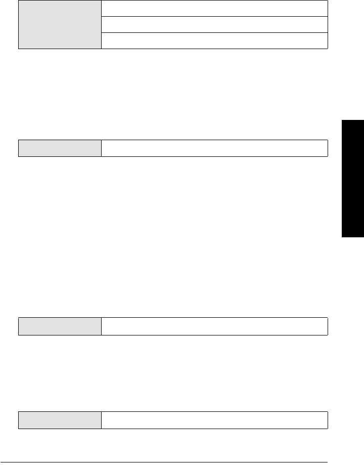
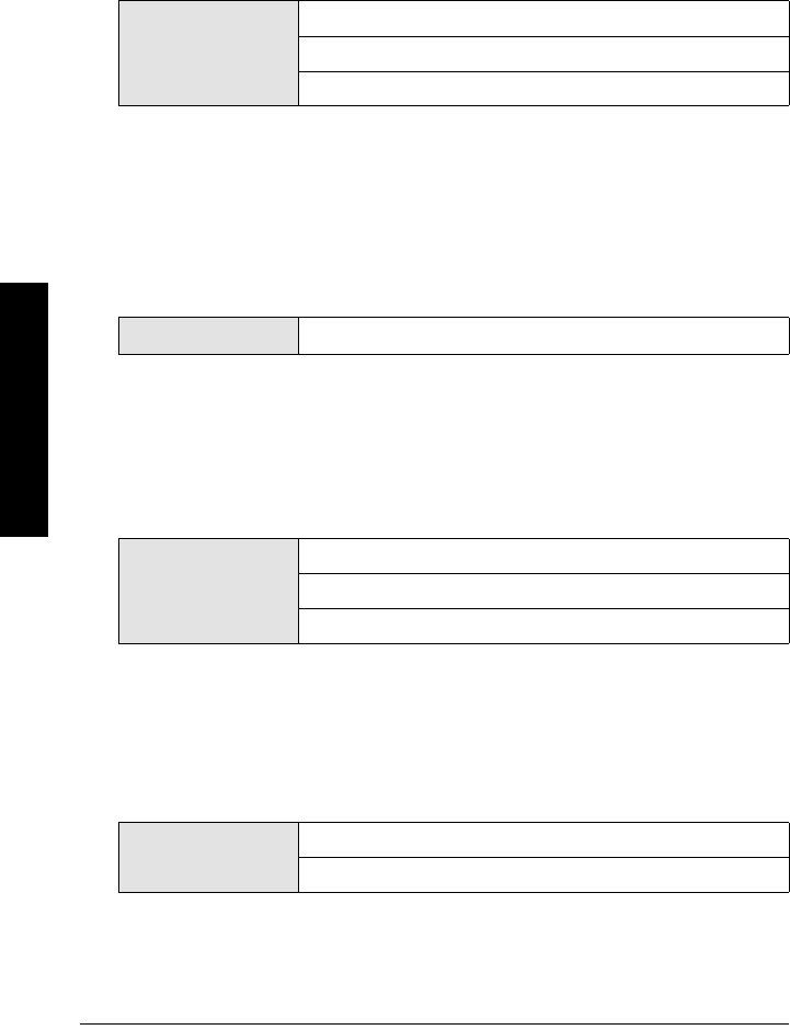
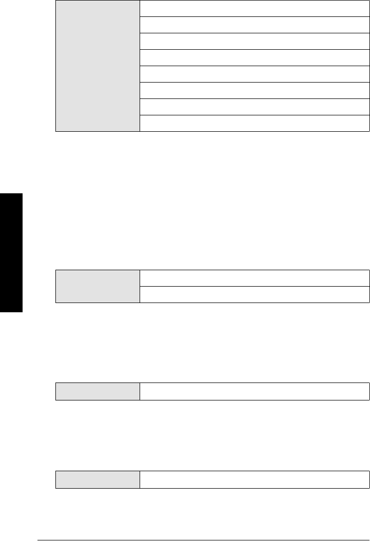
4.2.4.6: HYST Level (F = 0.5 m)
Hysteresis of the level limit values
Set the hysteresis of the limit values in the units system selected according to Parameter
4.1.1 (see diagram below).
Limit value alarm
4.2.5: Volume parameters
To calculate the volume of the measuring medium, you need the level parameters (see
parameter 4.2.4) in the units selected according to parameter 4.1.1 and additionally a
vessel characteristic (parameter 4.2.5.7).
4.2.5.1: Volume URV (F = 20 m3)
Full scale of the volume
4.2.5.2: Volume LRV (F = 0 m3)
Start of scale of the volume
4.2.5.3: Volume Damping (F = 1 s)
Damping of the volume
Value numerical value
Value numerical value
Value numerical value
Value numerical value
measuring variable
upper limit
value
time
hysteresis
measuring variable
lower limit
value
time
hysteresis
limit value
alarm
limit value
alarm
chap6.fm Page 40 Tuesday, October 9, 2001 2:26 PM
7ML19985FH01 SITRANS LR 400 – INSTRUCTION MANUAL DRAFT Page 41
mmmmm
Parameters (HART)
4.2.5.4: MinLim Volume (F = 0 m3)
Lower limit value of the volume
4.2.5.5: MaxLim Volume (F = 0 m3)
Upper limit value of the volume
4.2.5.6: HYST Volume (F = 0.5 m3)
Hysteresis of the volume limit values
4.2.5.7: Tank Characteristic (F = Calibrate/table)
Determining the vessel characteristic
Select the option “Calculate” or “Calibrate/Table” as required. The selection controls the
display of Parameter 4.2.5.8.
The possibilities of each parameter are listed below. For the values associated with
Parameter 4.2.5.8: Calculate, go to page 43.
4.2.5.8: Calibrate/table
If your vessel deviates from the forms offered, the necessary data is not available or is
unknown or you need a vessel characteristic with greater accuracy you must calibrate it
by liters. You can enter reference values from a table provided by the vessel
manufacturer or do the calibration manually and enter the determined reference values.
You can only enter pairs of values consisting of level and volume.
Value numerical value
Value numerical value
Value numerical value
Value Calibrate/table
Calculate
Note: Entering the vessel characteristic with the operation and monitoring module
can be a time-consuming procedure. It can be done more quickly and comfortably
with the SIMATIC PDM software. There, an entered table can be edited simply – an
option which is only conditionally possible with the operating and monitoring module.
chap6.fm Page 41 Tuesday, October 9, 2001 2:26 PM
Page 42 SITRANS LR 400 – INSTRUCTION MANUAL DRAFT 7ML19985FH01
mmmmm
Parameters (HART)
The 4.2.5.8: Calibrate parameter offers the following selection possibilities:
4.2.5.8.1: Calibrate
Here you can enter up to 50 reference values whose levels SITRANS LR 400 measures.
Enter the appropriate volume (determined by manual calibration).
If you access this parameter, first the currently measured level is displayed. Accept it by
pressing . Enter the appropriate volume, save it by pressing or reject it by pressing
.
Then the device displays the “Calibrate” selection again. Access again (press ) to
select a further reference value. The device automatically offers you the next undefined
reference value.
It is recommended to enter a maximum of two or three reference values for the linear
range of the vessel and to use the others for the non-linear portion
If you enter a second volume value for the same level, the reference value saved earlier is
overwritten.
4.2.5.8.2: Enter table
Manual entry of a table
Here you can enter up to 50 reference values provided by the vessel manufacturer in any
order.
The first reference value is offered when you access the parameter. Enter the level as a
distance from the floor of the vessel in the units selected according to parameter 4.1.1
(parameter “Enter level” and the volume corresponding to the level (parameter “Enter
volume”).
The device then displays the selection “Enter table” again. Access again to enter a
further reference value. The device automatically offers you the next undefined reference
value.
It is recommendable to enter a maximum of two or three reference values for the linear
range of the vessel and to use the others for the non-linear part.
If you enter a second volume value for the same level, the reference value saved earlier is
overwritten.
Value numerical value
chap6.fm Page 42 Tuesday, October 9, 2001 2:26 PM
7ML19985FH01 SITRANS LR 400 – INSTRUCTION MANUAL DRAFT Page 43
mmmmm
Parameters (HART)
4.2.5.8.3: Show table
Display table
Here you can display the entered reference values sorted on levels. In the second line,
the level corresponding to the first reference value appears first and then the
corresponding volume value when you switch further. Each switching accesses a further
reference value.
4.2.5.8.4: Clear table
Delete table
If you access the “all” selection in this parameter, the entire saved table is deleted. You
can delete individual reference values with the selection “1st”, “2nd” etc. which were
displayed in parameter 4.2.5.8.3.
or
4.2.5.8: Calculate
Automatic calculation of a vessel characteristic is faster than manual entry by calibrating
or a table. However, the calculated vessel characteristic is not as accurate as a manually
calibrated characteristic – especially in the non-linear areas of the vessel in which errors
of ≤ 1 % may occur. As well, the necessary data which you can get from the design
documents of your vessel must still correspond to the real conditions.
The 4.2.5.8: Calculate parameter requires the following parameters:
4.2.5.8.1: Tank Design (F = Vertical Cylinder)
Value selection
Value selection
Value
Linear
Vertical cylinder
Horizontal cylinder
sphere
Note: The reference values are sorted in order of filling states and do not necessarily
correspond to the order of the value pairs you have entered.
chap6.fm Page 43 Tuesday, October 9, 2001 2:26 PM
Page 44 SITRANS LR 400 – INSTRUCTION MANUAL DRAFT 7ML19985FH01
mmmmm
Parameters (HART)
Enter the external form of your vessel. You can choose from:
• Linear (any form with vertical walls and a flat floor)
• Vertical cylinder (vertically standing cylindrical form with curved covers)
• Horizontal cylinder (horizontal cylindrical form with curved caps)
• Sphere
4.2.5.8.2: Bottom Design (F = Dished end)
Enter the form of the two vessel cover caps. You can choose from:
• Dished (according to DIN 28011)
• Basket (according to DIN 28013)
• Bullet (hemispherical shaped floor)
4.2.5.8.3: Tank volume (F = 20 m3)
4.3: Analog Output
4.3.1: Error Level (F = D: Error Signal)
Level for the error signal to alarm in Analog or Digital output
When D is selected, all errors are displayed. When D+F is selected, there is special
handling for failsafe. When D+F+W is selected, there is special handling for warnings.
4.3.2: AO Select (F = Level)
Assignment of a measured value to the analog output
Here you can set whether the analog output supplies the level or the volume to the
control system.
The selection controls the following parameter 4.3.3.
Value
Dished end
Basket end
Bullet bottom
Value numerical value
Value
D: Error Signal
D+F: Error Signal
D+F+W: Error Signal
Values Level
Volume
chap6.fm Page 44 Tuesday, October 9, 2001 2:26 PM
7ML19985FH01 SITRANS LR 400 – INSTRUCTION MANUAL DRAFT Page 45
mmmmm
Parameters (HART)
4.3.3: Level Parameter (= Parameter 4.2.4)
or
4.3.3: Volume Parameter (= Parameter 4.2.5)
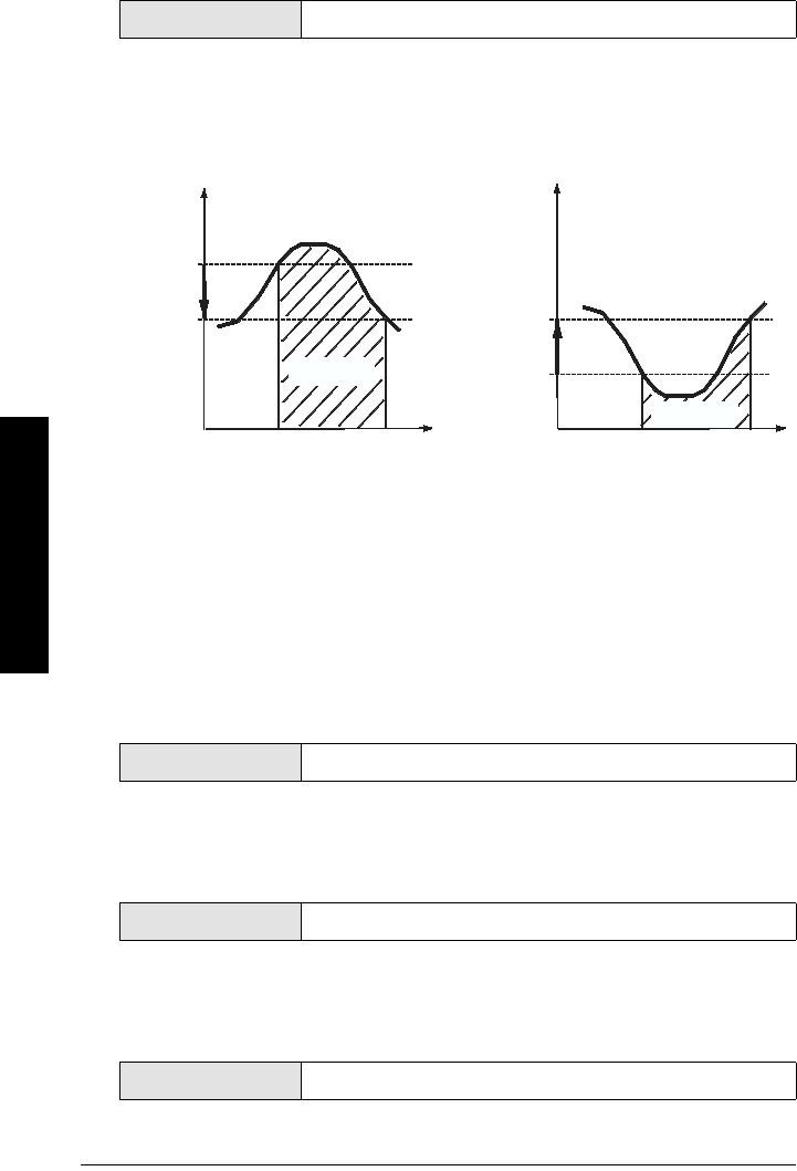
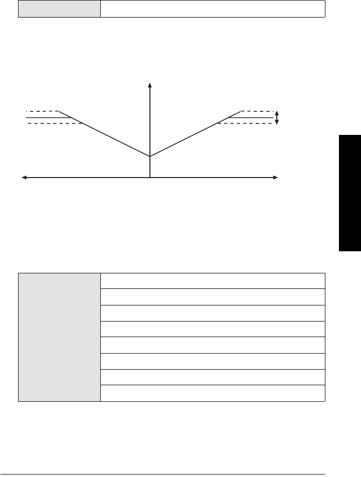
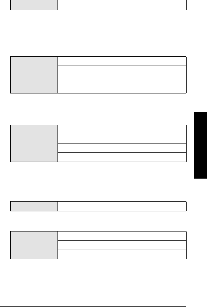
4.3.4: Current Limit (F = 20 mA)
Upper current limit
Here you can set the upper current limit of the output signal in steps of 0.1 mA (see
Current limiting diagram below).
Current limiting
The URV is always at 20 mA. If you set the current limit to a higher value, you can have the
measured values output outside the measuring range (up to approx. 115%).
4.3.5: Error Signal (F = 3.6 mA)
Current value of the error signal
In the event of a fault the device applies the current defined here to the analog output.
You can choose between 3.6 mA, 22 mA, 24 mA, Hold 10 s, Hold 1 min, Hold 2 min, Hold 3
min and Hold permanent.
Value 20 - 22.5 mA
Value
3.6 mA
22.0 mA
24.0 mA
Hold 10 s
Hold 1 min
Hold 2 min
Hold 3 min
Hold continuously
setting range
22,5 mA
20,0 mA
measured value
current
chap6.fm Page 45 Tuesday, October 9, 2001 2:26 PM
Page 46 SITRANS LR 400 – INSTRUCTION MANUAL DRAFT 7ML19985FH01
mmmmm
Parameters (HART)
In the “Hold...” parameters, the device outputs the last valid value until the set time has
run out or the fault has been eliminated. If the fault persists after the set time runs out,
the analog output switches to an error signal of 3.6 mA.
4.4 Digital Output
4.4.1: parameter DO (F = Alarm)
Assignment of the digital output
Here you can select whether the digital output supplies the upper or lower limit value of
level or volume or an alarm (device error, measurement error; see parameter 3.1) to the
control system. If you select the “No function” option, the digital output is switched off.
Selection of a limit value enables parameter 4.4.3.
4.4.2: Error Level (F = D: Error Signal)
Level for the error signal to alarm in Analog or Digital output
When D is selected, all errors are displayed. When D+F is selected, there is special
handling for failsafe. When D+F+W is selected, there is special handling for warnings.
4.4.3: Signal Type DO (F = Relay closes)
Here you can determine the behavior of the digital output. Select whether its contact
closes or opens at an event.
Value
MaxLim Level
MinLim Level
MaxLim Volume
MinLim Volume
Alarm
No Function
Value
D: Error Signal
D+F: Error Signal
D+F+W: Error Signal
Value Relay closes
Relay opens
chap6.fm Page 46 Tuesday, October 9, 2001 2:26 PM
7ML19985FH01 SITRANS LR 400 – INSTRUCTION MANUAL DRAFT Page 47
mmmmm
Parameters (HART)
The following parameters are only enabled when the digital output supplies a limit value.
4.6.9.6: Antenna offset (see page 51)
4.6.9.7: Reference distance (see page 51)
4.4.4: Level Parameter (= Parameter 4.2.4)
or
4.4.4: Volume Parameter (= Parameter 4.2.5)
4.5: Display Parameters
4.5.1: Multi-Display
4.5.1.1: Line 1 Local (F = Level)
Choice of measured value in line 1
4.5.1.2: Display Local (F = Eng Unit)
Method of display in line 1
4.5.1.3: Level Parameter (= Parameter 4.2.4)
or
4.5.1.3: Volume Parameter (= Parameter 4.2.5)
Value Level
Volume
Value
Eng unit
%
Bar graph
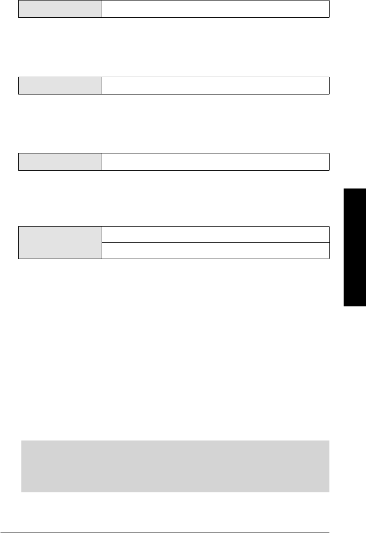
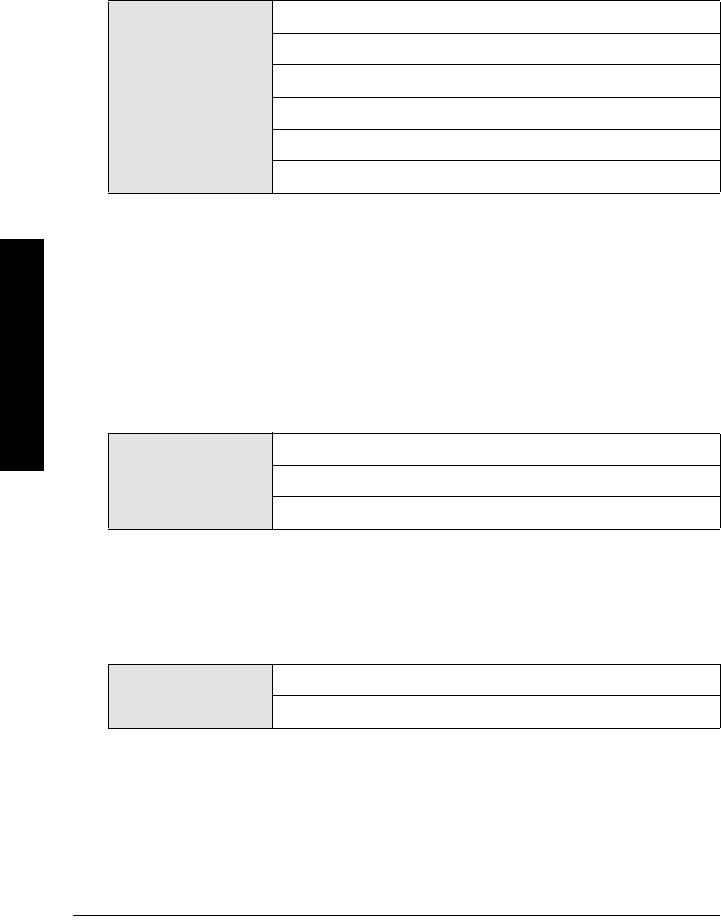
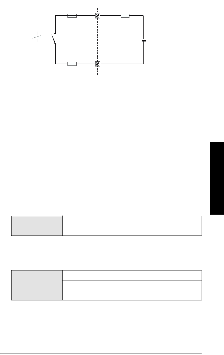
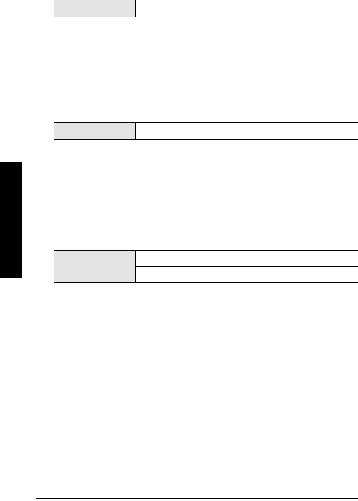
electronic fuse
External supply
9 W
Device
chap6.fm Page 47 Tuesday, October 9, 2001 2:26 PM
Page 48 SITRANS LR 400 – INSTRUCTION MANUAL DRAFT 7ML19985FH01
mmmmm
Parameters (HART)
4.5.1.4: Line 2 Local (F = S/N ratio)
Display in line 2
4.5.1.5: Level Parameter (= Parameter 4.2.4)
or
4.5.1.5: Volume Parameter (= Parameter 4.2.5)
4.5.2: Language Local (= parameter 1.1)
4.5.3: LCD Lighting (F = off)
Background illumination of the LCD
4.6: Device Information
4.6.1: Power Supply (F according to customer specifications)
Voltage range of the built-in power supply unit
4.6.2: Flange Temperature (according to customer
specifications)
Temperature range of the flange in °C
Value
Level
Volume
Te m p e ra t ur e
Validity
S/N ratio
Amplitude
Digital output
Analog output
Value on
off
Value non-editable
Value non-editable
chap6.fm Page 48 Tuesday, October 9, 2001 2:26 PM
7ML19985FH01 SITRANS LR 400 – INSTRUCTION MANUAL DRAFT Page 49
mmmmm
Parameters (HART)
4.6.3: Electrical Connection (according to customer
specifications
4.6.4: Antenna and Flange
4.6.4.1: Flange Size (according to customer specifications)
Size of the flange
4.6.4.2: Flange Type (according to customer specifications)
Type of flange
4.6.4.3: Pressure Stage (according to customer
specifications)
Pressure range of the process connection
4.6.4.4: Antenna Type (according to customer settings)
Value non-editable
Value
DN 80, 3 in
DN 100, 4 in
DN 150, 6 in
Special Design
Value
DIN 2527
ANSI
JIS
Special Design
Value non-editable
Value
Horn type long
Horn type short
Special design
chap6.fm Page 49 Tuesday, October 9, 2001 2:26 PM

Page 50 SITRANS LR 400 – INSTRUCTION MANUAL DRAFT 7ML19985FH01
mmmmm
Parameters (HART)
4.6.4.6: Flange Material (according to customer
specifications)
4.6.4.7: Seal Material (according to customer
specifications)
Sealing material
4.6.5: Tag (according to customer specifications)
Device identification
4.6.6: Descriptor (according to customer specifications)
Measuring point description
4.6.7: Message (according to customer specifications)
Measuring point message, e.g. the date of the last check or clean
4.6.8: Manufacturer Identification
4.6.8.1: Serial Number (F = unique number)
Factory serial number
Value 316/316L
Special Design
Value
Te f l o n
Kalrez
Viton
Perbunan
Special Design
Value up to any eight characters
Value up to any 16 characters
Value up to any 32 characters
Value non-editable
chap6.fm Page 50 Tuesday, October 9, 2001 2:26 PM

7ML19985FH01 SITRANS LR 400 – INSTRUCTION MANUAL DRAFT Page 51
mmmmm
Parameters (HART)
4.6.8.2: Order Number (according to customer
specifications)
Device order number (delivery state)
4.6.8.3: Fld Dev Rev (F = Number)
Device version
4.6.8.4: Software Revision (F = Number)
4.6.8.5: Hardware Revision (F = Number)
4.6.8.6: Antenna Offset (F = approx. 0.5 m [calibration value])
Distance sensor/flange
The antenna offset defines the propagation time of the measuring signal between the
sensor and the flange as a distance. It is preset at the factory and cannot be changed.
4.6.8.7: Reference Difference (F = approx. 106 m [calibration
value])
Internal reference distance
The length of the reference distance in the units system selected according to parameter
4.1.5 can only be read out and not changed. The device uses this to calibrate itself so that
no manual adjustment is necessary in long-term operation.
Value non-editable
Value non-editable
Value non-editable
Value non-editable
chap6.fm Page 51 Tuesday, October 9, 2001 2:26 PM
Page 52 SITRANS LR 400 – INSTRUCTION MANUAL DRAFT 7ML19985FH01
mmmmm
Parameters (HART)
5. Options
5.1: Enter Code
Input of customer code to enable programmability
The device compares a code number which you enter here with the code number defined
by parameter 5.2. If your entry matches the customer code completely, it releases the
programming lock for all parameters. Any other code number locks and disables
programming.
5.2: Customer Code (F = 0)
Determination of customer code
Here you define the up to four digit long *customer code with which you can protect the
device parameters against undesirable programming errors.
Meaning and parameter of the customer code are explained in “Disabling and enabling
programming” on page 22
5.3: Factory Reset (F = no)
Reset all parameters to factory setting
This parameter allows you to reset all parameters to the original factory setting as
described in “Parameters (HART)” on page 25.
Value Customer code
Value up to 4-digit code
Value yes
no
chap6.fm Page 52 Tuesday, October 9, 2001 2:26 PM

7ML19985FH01 SITRANS LR 400 – INSTRUCTION MANUAL DRAFT Page 53
mmmmm
Parameters (Profibus PA)
Parameters (Profibus PA)
Parameters (Profibus PA)
Device parameter,
parameter, menu
identification Description Factory
Setting Setting
Possibilities
1: Auto-Setup
Language local Language of the local
user interface
English English
Deustch
Length Unit m cm
m
mm
ft
in
Nozzle height Height flange to top of
tank
0 m numerical value
Tank Height Height tank bottom to top 20 m numerical value
Level URV Full scale of level (see
Functional Dimensions
Diagram)
20 m numerical value
Level LRV Start of scale of level (See
Functional Dimensions
Diagram)
0 m numerical value
Level damping Damping of level in s 1 s numerical value
Application type Use of the vessel Liquid (store) Liquid (store)
Liquid (process)
Silo1 (solids)
Silo2 (solids)
User tank1
User tank2
1.8: Bus address Current bus address 126 numerical value
2: Display
2.1: Multi-display Display of two measured
values
Level in Sig-
nal-to-noise
ratio in dB
non-editable
2.2: Level Level of measured
medium
m non-editable
2.3: Volume Volume of measured
medium
m3non-editable
2.5: Current Output Value of the analog output
in mA
non-editable
3: Diagnostics
chap6.fm Page 53 Tuesday, October 9, 2001 2:26 PM

Page 54 SITRANS LR 400 – INSTRUCTION MANUAL DRAFT 7ML19985FH01
mmmmm
Parameters (Profibus PA)
3.1: Status
3.1.1: Wear
3.1.1.1: Operating
Hours
Total previous operating
time of the device in
hours (approximate value)
non-editable
3.1.1.2: Maximum
temp.
Previous maximum tem-
perature of device
26°C non-editable
3.1.1.3: Minimum
temp.
Previous minimum tem-
perature of the device
26°C non-editable
3.1.1.4: Aging Approximate value for the
previous life of the device
in % (100% = approx. 10
years)
non-editable
3.1.1.5: Hours > 85°C Previous time during
which the maximum per-
missible sensor tempera-
ture was exceeded in
hours
non-editable
3.1.x: Sensor
and/or
3.1.x: Electronics
and/or
3.1.x: Software
and/or
3.1.x: Application
and/or
3.1.x: Parameters
and/or
3.1.x: Service
Diagnostic messages of
the sensor
non-editable
Diagnostic messages of
the electronics
non-editable
Diagnostic messages of
the software
non-editable
Diagnostic messages to
the application
non-editable
Display of the false
parameters
non-editable
for service purposes only non-editable
3.2: Device test
3.2.1: Self-test Check device state non-editable
3.2.2: Display test Visual check of LCD non-editable
3.3: Sensor variables
3.3.1: Raw value Distance from flange to
measured medium
3.3.2: Echo Amplitude Measure of quality of
reflection
3.3.3: S/N ratio Signal-to-noise ratio of
the measured value in dB
3.3.4: Validity Validity of the measured
value in %
Parameters (Profibus PA)
Device parameter,
parameter, menu
identification Description Factory
Setting Setting
Possibilities
chap6.fm Page 54 Tuesday, October 9, 2001 2:26 PM

7ML19985FH01 SITRANS LR 400 – INSTRUCTION MANUAL DRAFT Page 55
mmmmm
Parameters (Profibus PA)
3.3.5: SensorTemp Sensor temperature
4: Device data
4.1: Units
4.1.1 Length unit = [1.2]
4.1.2: Volume unit m3bbl
yd3
ft3
in3
bush
bbl (fl.)
l
m3
hL
Gal
ImpGal
4.1.4: Temperature
Unit
Unit of the sensor tem-
perature
°C °C
°F
K
4.1.5: Other units Units system for all other
units
SI SI unit
US/UK unit
4.2: Operating param-
eters
4.2.1: Tank geometry
4.2.1.1: Nozzle height = [1.3]
4.2.1.2: Tank height = [1.4]
4.2.1.3: Stilling pipe? Stilling pipe available? no yes
no
If yes: Pipe diameter Diameter (= internal) of
the stilling pipe
100 mm numerical value
4.2.2: Measuring con-
ditions
4.2.2.1: Applic. type Use of the tank Liquid (store) Liquid (store)
Liquid (process)
Silo1 (solids-pel-
lets)
Silo2 (solids-pow-
ders)
User tank1
User tank2
Parameters (Profibus PA)
Device parameter,
parameter, menu
identification Description Factory
Setting Setting
Possibilities
chap6.fm Page 55 Tuesday, October 9, 2001 2:26 PM

Page 56 SITRANS LR 400 – INSTRUCTION MANUAL DRAFT 7ML19985FH01
mmmmm
Parameters (Profibus PA)
4.2.2.2: Surface Surface structure of the
measured medium
Not displayed if a user
tank is selected in
[4.2.2.3].
wavy smooth
wavy
turbulent
4.2.2.3: Dead band Area beneath the flange
in which measured values
are ignored
0.26 m numerical value,
Minimum value =
Length of the
antenna
4.2.2.4: Correction
factor
Correction factor for
physical measuring influ-
ences
1.0 numerical value
4.2.2.5: Filling speed Typical speed of change
of the level
Not displayed if a user
tank is selected in
[4.2.2.3].
200 mm/min numerical value
4.2.2.7: Failsafe Level Selects the default mea-
surement in the even the
failsafe timer expires
Hold 100 %
0 %
Hold
4.2.2.8: Failsafe Timer Sets the time delay, in
minutes, before going into
fail-safe level
10 min 1 min
2 min
etc.
4.2.2.9: Range Exten-
sion
Sets the distance below
the tank height included
in the evaluation
3 m 1 m
2 m
etc.
4.2.3: Sensor param-
eter
4.2.3.1: Sensor damp-
ing
Averaging of measuring
signal
Not displayed if a user
tank is selected in
[4.2.2.3].
10 s numerical value
4.2.3.2: Multiple echo Evaluate multiple echo on on
off
4.2.3.3: Echo motion Evaluate echo motion on on
off
4.2.3.4: Window
tracking
on on
off
4.2.3.5: Tank empty
detect.
on on
off
4.2.3.6: Auto fix dist. Automatic fixed target
detection
on on
off
Parameters (Profibus PA)
Device parameter,
parameter, menu
identification Description Factory
Setting Setting
Possibilities
chap6.fm Page 56 Tuesday, October 9, 2001 2:26 PM

7ML19985FH01 SITRANS LR 400 – INSTRUCTION MANUAL DRAFT Page 57
mmmmm
Parameters (Profibus PA)
4.2.3.7: Fix dist. list Manual input of up to nine
fixed targets
numerical values
4.2.3.9: Auto False
Echo Suppression
Learns and records the
current signal up to the
suppression distance set-
ting. These signals are
then ignored during oper-
ation
use use
record
off
4.2.3.A: Auto False
Echo Suppression
Distance
Defines the end point of
the Auto False echo
suppression distance
0 m variable
4.2.4: Level param.
4.2.4.1: Level URV = [1.5]
4.2.4.2: Level LRV = [1.6]
4.2.4.3: Level damp-
ing
= [1.7]
4.2.4.4: Min Warn
level
Limit before reach lower
limit value
0 m numerical value
4.2.4.5: MinLim level Lower limit value of the
level (See Functional
Dimensions Diagram)
0 m numerical value
4.2.4.6: MaxLim level Upper limit value of the
level (See Functional
Dimensions Diagram)
0 m numerical value
4.2.4.7: MaxWarn
level
Limit before reach upper
limit value
0 m numerical value
4.2.4.8: HYST level Hysteresis of the level
limit values
0.5 m numerical value
4.2.5: Volume param.
4.2.5.1: Volume URV Full scale of the volume 20 m3numerical value
4.2.5.2: Volume LRV Start of scale of the vol-
ume
0 m3numerical value
4.2.5.3: Volume
damping
Damping of the volume 1 s numerical value
4.2.5.4: MinWarn vol-
ume
Limit before reach lower
limit value
0 m numerical value
4.2.5.5: MinLim vol-
ume
Lower limit value of the
volume
0 m3numerical value
4.2.5.6: MaxLim vol-
ume
Upper limit value of the
volume
0 m3numerical value
Parameters (Profibus PA)
Device parameter,
parameter, menu
identification Description Factory
Setting Setting
Possibilities
chap6.fm Page 57 Tuesday, October 9, 2001 2:26 PM

Page 58 SITRANS LR 400 – INSTRUCTION MANUAL DRAFT 7ML19985FH01
mmmmm
Parameters (Profibus PA)
4.2.5.7: MaxWarn vol-
ume
Limit before reach upper
limit value
0 m numerical value
4.2.5.8: HYST volume Hysteresis of the volume
limit values 0.5 m3numerical value
4.2.5.0: Tank charac-
teristic
Determining the tank
characteristic
Calibrate/
table
Calibrate/table
Calculate
4.2.5.A: Calibrate/table
or
4.2.5.A: Calculate
4.2.5.A.1: Calibrate
or
4.2.5.A.1: Tank design
Automatic litering Confirm input
Vertical cylin-
der
Linear
Vertical cylinder
Horizontal
Cylinder
Sphere
4.2.5.A.2: Enter table
or
4.2.5.A.2: Bottom
design
Manual entry of a table numerical value
Dished end Dished end
Basket end
Bullet bottom
4.2.5.A.3: Show table
or
4.2.5.A.3: Tank vol-
ume
Display table Selection
20 m3numerical value
4.2.5.A.4: Clear table
or
4.2.5.A.4: Tank height
Delete table Selection
= [4.2.1.2]
4.3: Output parame-
ter
4.3.1: BusIdentNr. Profile specific
Manufacturer spe-
cific
4.3.2: Bus address = [1.8}
4.4: Display param.
4.4.1: Multi display
4.4.1.1: Line 1 local Choice of measured value
in line 1
Level Level
Volume
4.4.1.2: Display local Method of display in line 1 Eng unit Eng unit
%
Bargraph
Parameters (Profibus PA)
Device parameter,
parameter, menu
identification Description Factory
Setting Setting
Possibilities
chap6.fm Page 58 Tuesday, October 9, 2001 2:26 PM