Siemens Canada Siemens Milltronics Process Instruments LR400 SITRANS LR 400 User Manual sitranslrd3
Siemens Canada Ltd. - Siemens Milltronics Process Instruments SITRANS LR 400 sitranslrd3
Contents
- 1. users manual 1
- 2. users manual 2
- 3. users manual 3
users manual 2
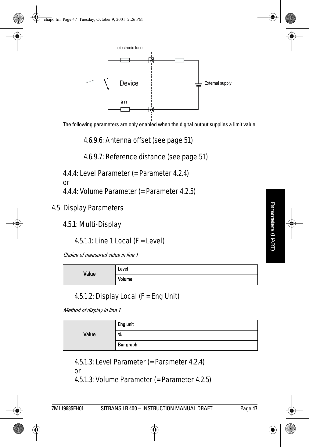
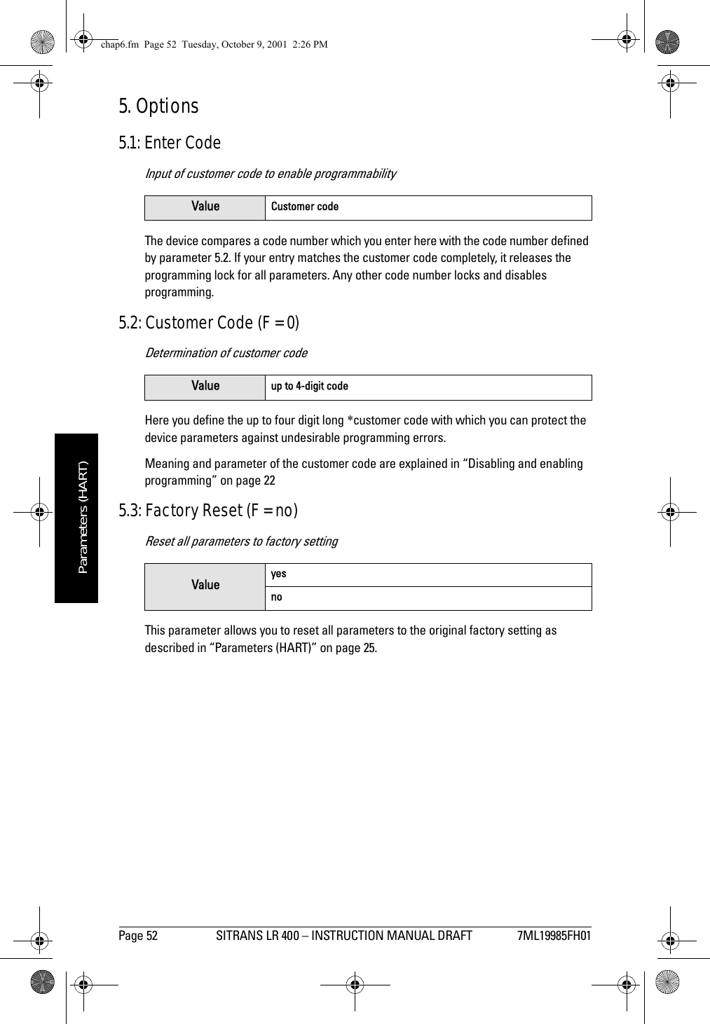
![7ML19985FH01 SITRANS LR 400 – INSTRUCTION MANUAL DRAFT Page 51mmmmmParameters (HART)4.6.8.2: Order Number (according to customer specifications)Device order number (delivery state)4.6.8.3: Fld Dev Rev (F = Number)Device version4.6.8.4: Software Revision (F = Number)4.6.8.5: Hardware Revision (F = Number)4.6.8.6: Antenna Offset (F = approx. 0.5 m [calibration value])Distance sensor/flangeThe antenna offset defines the propagation time of the measuring signal between the sensor and the flange as a distance. It is preset at the factory and cannot be changed.4.6.8.7: Reference Difference (F = approx. 106 m [calibration value])Internal reference distanceThe length of the reference distance in the units system selected according to parameter 4.1.5 can only be read out and not changed. The device uses this to calibrate itself so that no manual adjustment is necessary in long-term operation.Value non-editableValue non-editableValue non-editableValue non-editablechap6.fm Page 51 Tuesday, October 9, 2001 2:26 PM](https://usermanual.wiki/Siemens-Canada-Siemens-Milltronics-Process-Instruments/LR400.users-manual-2/User-Guide-174195-Page-13.png)
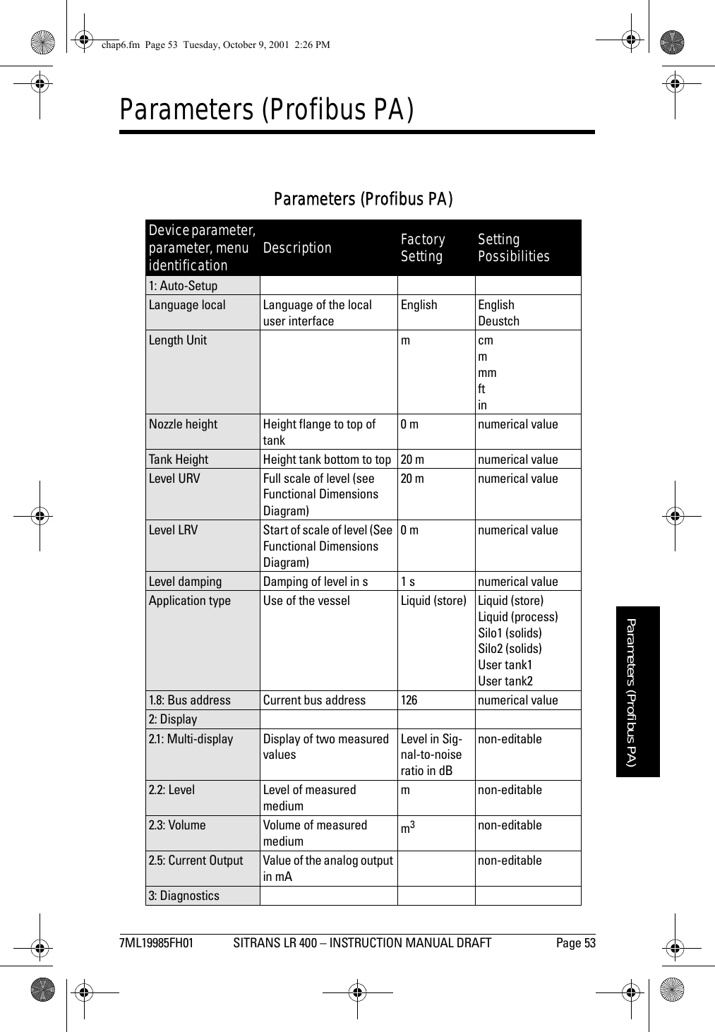
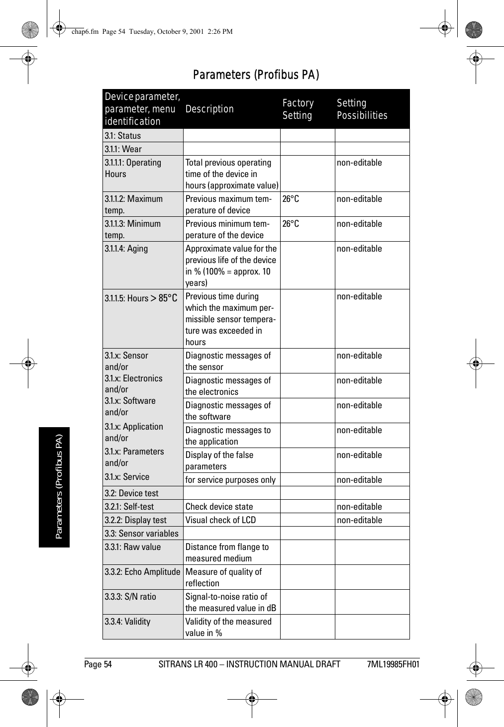
![7ML19985FH01 SITRANS LR 400 – INSTRUCTION MANUAL DRAFT Page 55mmmmmParameters (Profibus PA)3.3.5: SensorTemp Sensor temperature4: Device data4.1: Units4.1.1 Length unit = [1.2]4.1.2: Volume unit m3bblyd3ft3in3bushbbl (fl.)lm3hLGalImpGal4.1.4: Temperature UnitUnit of the sensor tem-perature°C °C°FK4.1.5: Other units Units system for all other unitsSI SI unitUS/UK unit4.2: Operating param-eters4.2.1: Tank geometry4.2.1.1: Nozzle height = [1.3]4.2.1.2: Tank height = [1.4]4.2.1.3: Stilling pipe? Stilling pipe available? no yesnoIf yes: Pipe diameter Diameter (= internal) of the stilling pipe100 mm numerical value4.2.2: Measuring con-ditions 4.2.2.1: Applic. type Use of the tank Liquid (store) Liquid (store)Liquid (process)Silo1 (solids-pel-lets)Silo2 (solids-pow-ders)User tank1User tank2Parameters (Profibus PA)Device parameter, parameter, menu identification Description Factory Setting Setting Possibilitieschap6.fm Page 55 Tuesday, October 9, 2001 2:26 PM](https://usermanual.wiki/Siemens-Canada-Siemens-Milltronics-Process-Instruments/LR400.users-manual-2/User-Guide-174195-Page-17.png)
![Page 56 SITRANS LR 400 – INSTRUCTION MANUAL DRAFT 7ML19985FH01mmmmmParameters (Profibus PA)4.2.2.2: Surface Surface structure of themeasured mediumNot displayed if a user tank is selected in [4.2.2.3].wavy smoothwavyturbulent4.2.2.3: Dead band Area beneath the flange in which measured values are ignored0.26 m numerical value,Minimum value = Length of the antenna4.2.2.4: Correction factorCorrection factor for physical measuring influ-ences1.0 numerical value4.2.2.5: Filling speed Typical speed of change of the levelNot displayed if a user tank is selected in [4.2.2.3].200 mm/min numerical value4.2.2.7: Failsafe Level Selects the default mea-surement in the even the failsafe timer expiresHold 100 %0 %Hold4.2.2.8: Failsafe Timer Sets the time delay, in minutes, before going into fail-safe level10 min 1 min2 minetc.4.2.2.9: Range Exten-sionSets the distance below the tank height included in the evaluation3 m 1 m2 metc.4.2.3: Sensor param-eter4.2.3.1: Sensor damp-ingAveraging of measuring signalNot displayed if a user tank is selected in [4.2.2.3].10 s numerical value4.2.3.2: Multiple echo Evaluate multiple echo on onoff4.2.3.3: Echo motion Evaluate echo motion on onoff4.2.3.4: Window trackingon onoff4.2.3.5: Tank empty detect.on onoff4.2.3.6: Auto fix dist. Automatic fixed target detectionon onoffParameters (Profibus PA)Device parameter, parameter, menu identification Description Factory Setting Setting Possibilitieschap6.fm Page 56 Tuesday, October 9, 2001 2:26 PM](https://usermanual.wiki/Siemens-Canada-Siemens-Milltronics-Process-Instruments/LR400.users-manual-2/User-Guide-174195-Page-18.png)
![7ML19985FH01 SITRANS LR 400 – INSTRUCTION MANUAL DRAFT Page 57mmmmmParameters (Profibus PA)4.2.3.7: Fix dist. list Manual input of up to nine fixed targetsnumerical values4.2.3.9: Auto False Echo SuppressionLearns and records the current signal up to the suppression distance set-ting. These signals are then ignored during oper-ationuse userecordoff4.2.3.A: Auto False Echo Suppression DistanceDefines the end point of the Auto False echosuppression distance0 m variable4.2.4: Level param.4.2.4.1: Level URV = [1.5]4.2.4.2: Level LRV = [1.6]4.2.4.3: Level damp-ing= [1.7]4.2.4.4: Min Warn levelLimit before reach lower limit value0 m numerical value4.2.4.5: MinLim level Lower limit value of the level (See Functional Dimensions Diagram)0 m numerical value4.2.4.6: MaxLim level Upper limit value of the level (See Functional Dimensions Diagram)0 m numerical value4.2.4.7: MaxWarn levelLimit before reach upper limit value0 m numerical value4.2.4.8: HYST level Hysteresis of the level limit values0.5 m numerical value4.2.5: Volume param.4.2.5.1: Volume URV Full scale of the volume 20 m3numerical value4.2.5.2: Volume LRV Start of scale of the vol-ume0 m3numerical value4.2.5.3: Volume dampingDamping of the volume 1 s numerical value4.2.5.4: MinWarn vol-umeLimit before reach lower limit value0 m numerical value4.2.5.5: MinLim vol-umeLower limit value of the volume0 m3numerical value4.2.5.6: MaxLim vol-umeUpper limit value of the volume0 m3numerical valueParameters (Profibus PA)Device parameter, parameter, menu identification Description Factory Setting Setting Possibilitieschap6.fm Page 57 Tuesday, October 9, 2001 2:26 PM](https://usermanual.wiki/Siemens-Canada-Siemens-Milltronics-Process-Instruments/LR400.users-manual-2/User-Guide-174195-Page-19.png)
![Page 58 SITRANS LR 400 – INSTRUCTION MANUAL DRAFT 7ML19985FH01mmmmmParameters (Profibus PA)4.2.5.7: MaxWarn vol-umeLimit before reach upper limit value0 m numerical value4.2.5.8: HYST volume Hysteresis of the volume limit values 0.5 m3numerical value4.2.5.0: Tank charac-teristicDetermining the tank characteristicCalibrate/tableCalibrate/tableCalculate4.2.5.A: Calibrate/tableor 4.2.5.A: Calculate4.2.5.A.1: Calibrateor4.2.5.A.1: Tank designAutomatic litering Confirm inputVertical cylin-derLinearVertical cylinderHorizontalCylinderSphere4.2.5.A.2: Enter tableor4.2.5.A.2: Bottom designManual entry of a table numerical valueDished end Dished endBasket endBullet bottom4.2.5.A.3: Show tableor4.2.5.A.3: Tank vol-umeDisplay table Selection20 m3numerical value4.2.5.A.4: Clear tableor4.2.5.A.4: Tank heightDelete table Selection= [4.2.1.2]4.3: Output parame-ter4.3.1: BusIdentNr. Profile specificManufacturer spe-cific4.3.2: Bus address = [1.8}4.4: Display param.4.4.1: Multi display4.4.1.1: Line 1 local Choice of measured value in line 1Level LevelVolume4.4.1.2: Display local Method of display in line 1 Eng unit Eng unit%BargraphParameters (Profibus PA)Device parameter, parameter, menu identification Description Factory Setting Setting Possibilitieschap6.fm Page 58 Tuesday, October 9, 2001 2:26 PM](https://usermanual.wiki/Siemens-Canada-Siemens-Milltronics-Process-Instruments/LR400.users-manual-2/User-Guide-174195-Page-20.png)