Siemens Canada Siemens Milltronics Process Instruments LR400 SITRANS LR 400 User Manual sitranslrd3
Siemens Canada Ltd. - Siemens Milltronics Process Instruments SITRANS LR 400 sitranslrd3
Contents
- 1. users manual 1
- 2. users manual 2
- 3. users manual 3
users manual 3
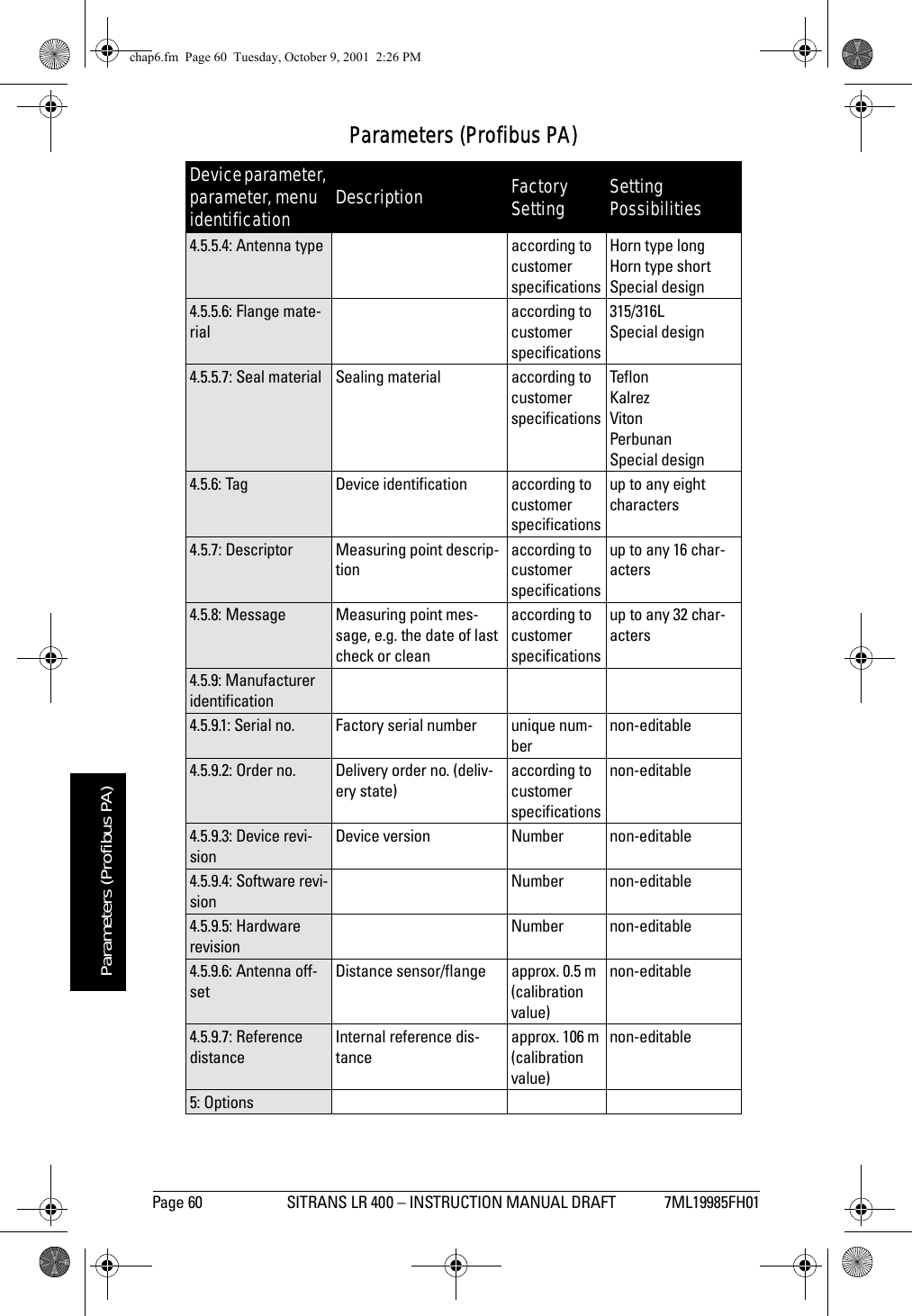
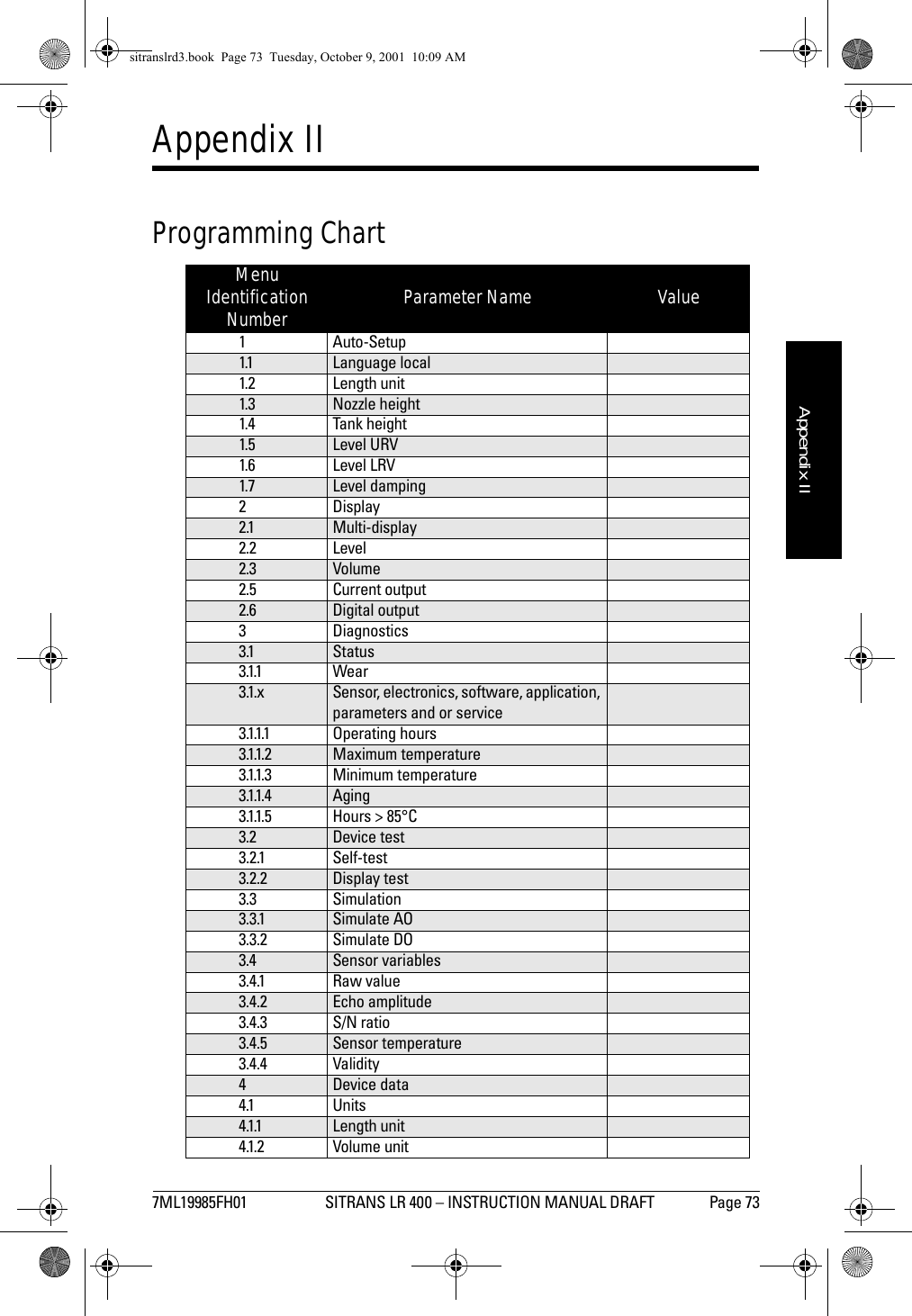
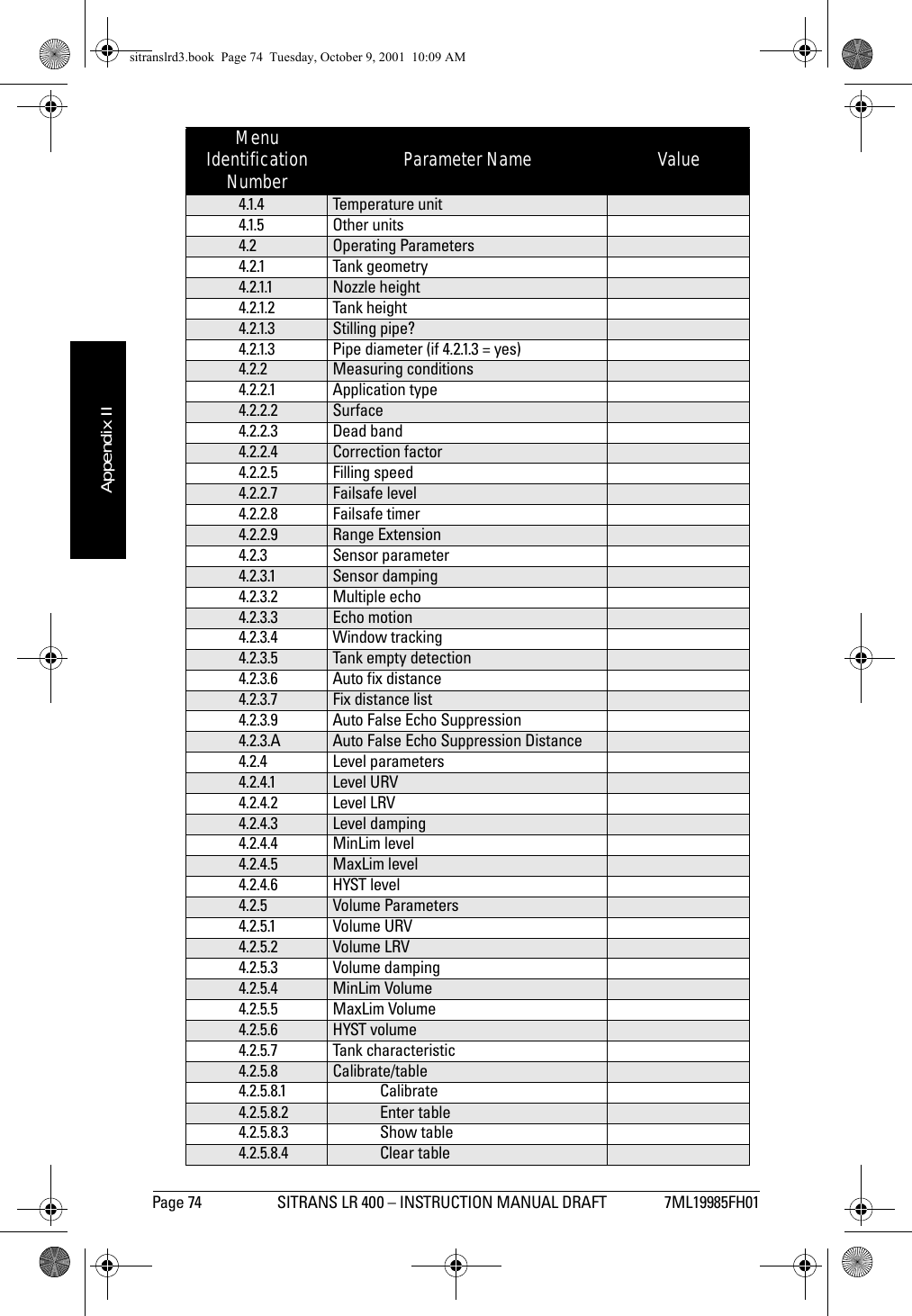
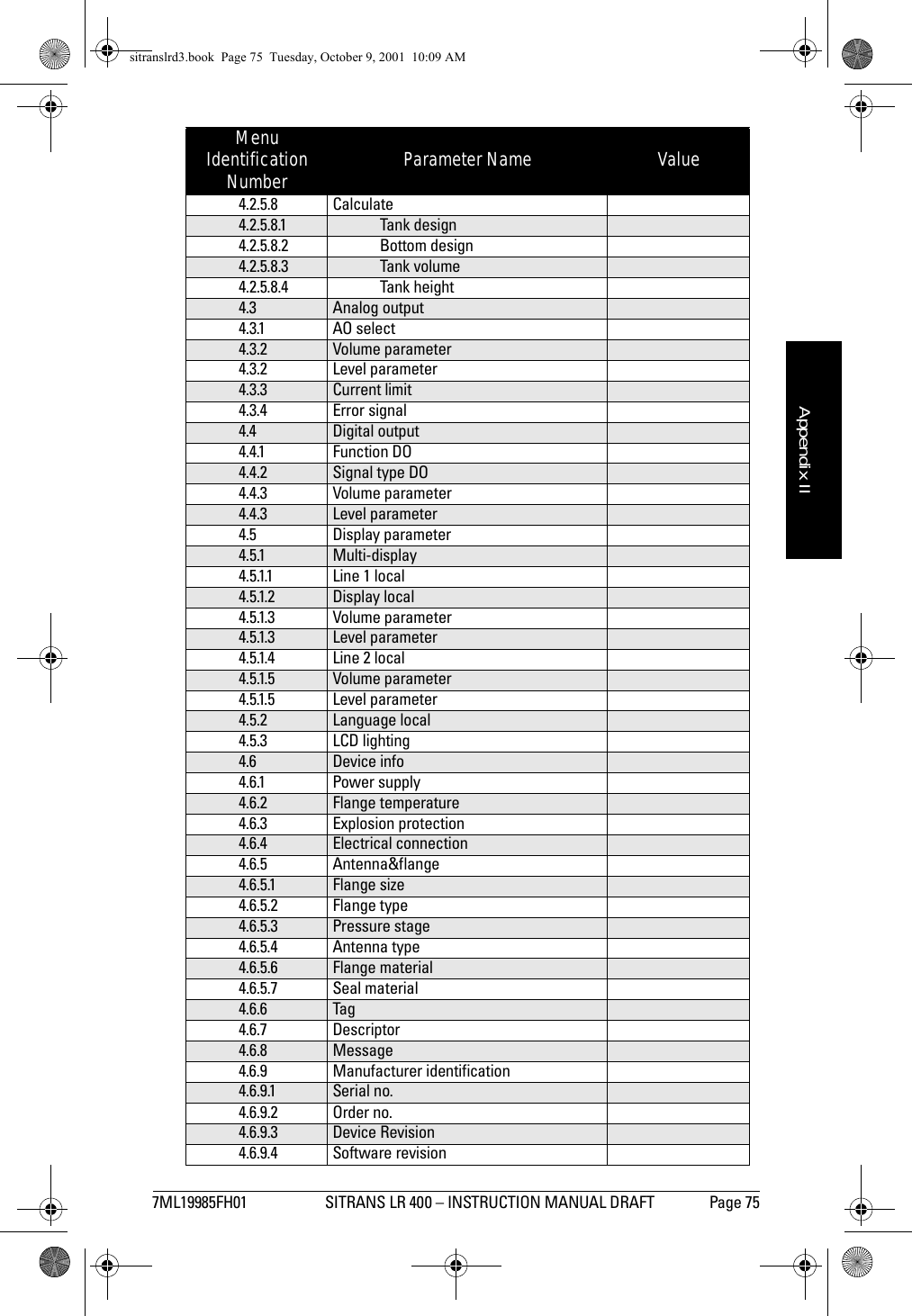
![7ML19985FH01 SITRANS LR 400 – INSTRUCTION MANUAL DRAFT Page 59mmmmmParameters (Profibus PA)4.4.1.3: Level param.or4.4.1.3: Volume param.= [4.2.4]= [4.2.5]4.4.1.4: Line 2 local Display in line 2 S/N ratio LevelVolumeTemp eratureValidityS/N ratioAmplitudeDigital outputAnalog output4.4.1.5: Level param. = [4.2.4]or4.4.1.5: Volume param.= [4.2.5]4.4.2: Language local = [1.1]4.4.3: LCD backlight Background illumination of the LCDoff onoff4.5: Device info4.5.1: Power supply Voltage range of the built-in power supply unitaccording to customer specificationsnon-editable4.5.2: Flange temper-atureTemperature range of the flange in °Caccording to customer specificationsnon-editable4.5.4: Electrical con-nectionaccording to customer specificationsnon-editable4.5.5: Antenna&flange4.5.5.1: Flange size Rated width of the flange according to customer specificationsDN 50, 2 inDN 80, 3 inDN 100, 4 inDN 150, 6 inSpecial design4.5.5.2: Flange type Type of flange according to customer specificationsDINANSIJIS Special design4.5.5.3: Pressure rangePressure range of the process connectionaccording to customer specificationsnon-editableParameters (Profibus PA)Device parameter, parameter, menu identification Description Factory Setting Setting Possibilitieschap6.fm Page 59 Tuesday, October 9, 2001 2:26 PM](https://usermanual.wiki/Siemens-Canada-Siemens-Milltronics-Process-Instruments/LR400.users-manual-3/User-Guide-174196-Page-1.png)