Siemens Canada Siemens Milltronics Process Instruments LR400 SITRANS LR 400 User Manual sitranslrd3
Siemens Canada Ltd. - Siemens Milltronics Process Instruments SITRANS LR 400 sitranslrd3
Contents
- 1. users manual 1
- 2. users manual 2
- 3. users manual 3
users manual 3

7ML19985FH01 SITRANS LR 400 – INSTRUCTION MANUAL DRAFT Page 59
mmmmm
Parameters (Profibus PA)
4.4.1.3: Level param.
or
4.4.1.3: Volume
param.
= [4.2.4]
= [4.2.5]
4.4.1.4: Line 2 local Display in line 2 S/N ratio Level
Volume
Temp erature
Validity
S/N ratio
Amplitude
Digital output
Analog output
4.4.1.5: Level param. = [4.2.4]
or
4.4.1.5: Volume
param.
= [4.2.5]
4.4.2: Language local = [1.1]
4.4.3: LCD backlight Background illumination
of the LCD
off on
off
4.5: Device info
4.5.1: Power supply Voltage range of the built-
in power supply unit
according to
customer
specifications
non-editable
4.5.2: Flange temper-
ature
Temperature range of the
flange in °C
according to
customer
specifications
non-editable
4.5.4: Electrical con-
nection
according to
customer
specifications
non-editable
4.5.5:
Antenna&flange
4.5.5.1: Flange size Rated width of the flange according to
customer
specifications
DN 50, 2 in
DN 80, 3 in
DN 100, 4 in
DN 150, 6 in
Special design
4.5.5.2: Flange type Type of flange according to
customer
specifications
DIN
ANSI
JIS
Special design
4.5.5.3: Pressure
range
Pressure range of the
process connection
according to
customer
specifications
non-editable
Parameters (Profibus PA)
Device parameter,
parameter, menu
identification Description Factory
Setting Setting
Possibilities
chap6.fm Page 59 Tuesday, October 9, 2001 2:26 PM

Page 60 SITRANS LR 400 – INSTRUCTION MANUAL DRAFT 7ML19985FH01
mmmmm
Parameters (Profibus PA)
4.5.5.4: Antenna type according to
customer
specifications
Horn type long
Horn type short
Special design
4.5.5.6: Flange mate-
rial
according to
customer
specifications
315/316L
Special design
4.5.5.7: Seal material Sealing material according to
customer
specifications
Tef lon
Kalrez
Viton
Perbunan
Special design
4.5.6: Tag Device identification according to
customer
specifications
up to any eight
characters
4.5.7: Descriptor Measuring point descrip-
tion
according to
customer
specifications
up to any 16 char-
acters
4.5.8: Message Measuring point mes-
sage, e.g. the date of last
check or clean
according to
customer
specifications
up to any 32 char-
acters
4.5.9: Manufacturer
identification
4.5.9.1: Serial no. Factory serial number unique num-
ber
non-editable
4.5.9.2: Order no. Delivery order no. (deliv-
ery state)
according to
customer
specifications
non-editable
4.5.9.3: Device revi-
sion
Device version Number non-editable
4.5.9.4: Software revi-
sion
Number non-editable
4.5.9.5: Hardware
revision
Number non-editable
4.5.9.6: Antenna off-
set
Distance sensor/flange approx. 0.5 m
(calibration
value)
non-editable
4.5.9.7: Reference
distance
Internal reference dis-
tance
approx. 106 m
(calibration
value)
non-editable
5: Options
Parameters (Profibus PA)
Device parameter,
parameter, menu
identification Description Factory
Setting Setting
Possibilities
chap6.fm Page 60 Tuesday, October 9, 2001 2:26 PM

7ML19985FH01 SITRANS LR 400 – INSTRUCTION MANUAL DRAFT Page 61
mmmmm
Parameters (Profibus PA)
5.1: Enter code Input of customer code to
enable programmability
Customer code
5.2: Customer code Determination of cus-
tomer code
0 up to 4 digit code
5.3: Factory reset Reset all parameters to
factory setting
no yes
no
Parameters (Profibus PA)
Device parameter,
parameter, menu
identification Description Factory
Setting Setting
Possibilities
chap6.fm Page 61 Tuesday, October 9, 2001 2:26 PM

Page 62 Sitrans LR 400 – INSTRUCTION MANUAL 7ML19985FH01
mmmmm
Troubleshooting
Troubleshooting
The SITRANS LR 400 has left the factory in a fully tested condition. Carefully selected
components and compliance with prescribed quality standards guarantee the high
reliability of the SITRANS LR 400. In the unlikely event of a fault, please consult the
instructions in this chapter before contacting the responsible customer services.
Classification of faults
Faults occurring in the SITRANS LR 400 can be classified in the following groups:
• faults caused by ambient influences: over and undertemperature, moisture,
contamination by the measuring medium and other substances, mains faults,
vibration
• faults in the device: display, electronics, mechanics, connections
Please try to determine the fault and localize it as accurately as possible..
If the fault cannot be eliminated with the measures described, follow the instructions in
“Maintenance and repairs” on page 65.
Self-test
If you get fault messages after the self-test, please proceed according to “Fault
messages” on page 64.
If there is a malfunction in the device, you can also activate the self-test manually with
Parameter 3.2.1.
Note: The device performs a self-test every time it is switched on. It is ready for
operation when the LCD displays the multi-display and the control elements can be
operated.
chap7.fm Page 62 Tuesday, October 9, 2001 1:06 PM

7ML19985FH01 Sitrans LR 400 – INSTRUCTION MANUAL Page 63
mmmmm
Troubleshooting
Symptoms, causes and their remedy
Symptom Possible causes Remedy
No display on the
LCD
Defective or missing
power supply
Check that the power supply is connected
correctly. Replace the device fuse if necessary
(see “Changing the device fuse” on page 65).
LCD is defective
Connect a HART Communicator or a PC/Laptop
with SIMATIC PDM software. If the device can be
parameterized from there, the LCD is defective.
Electronics are defective
Measure the analog current output. If the output
current is not between 3.6 mA < x < 22 mA, the
electronics are defective. Replace the electronics
unit as described in “Maintenance and repairs”
on page 65.
A fault message
is displayed Internal fault
Call the fault display in Function 3.1.
Proceed as described in “Maintenance and
repairs” on page 65.
An incorrect
measured value
appears after
Auto-Setup.
The device is not
parameterized correctly
according to the
application
Set the device parameters and functions
manually.
No measured
value appears
after the Auto-
Setup
(measured value
“0” and the fault
display flashes)
Internal fault
Call the fault display in Function 3.1.
Proceed as described in “Maintenance and
repairs” on page 65.
chap7.fm Page 63 Tuesday, October 9, 2001 1:06 PM

Page 64 Sitrans LR 400 – INSTRUCTION MANUAL 7ML19985FH01
mmmmm
Troubleshooting
Fault messages
The device indicates faults with a flashing letter on the right of the first line of the display.
It has the following meaning:
• W: Warning – device is still ready for operation but faults may occur
• F: Fault – sporadic fault, device conditionally ready for operation
• D: continuous fault – device is not ready for operation
Under Parameter 3.1.x, you will find a fault log which indicates the type of the fault(s)
which occur. It indicates the device function status in which the fault occurred and
outputs an fault message in plain text.
The possible fault messages are as follows:
1. Make the following modifications, starting with
a. Check whether the fault still occurs after every step:
b. Check the set measuring range and the dead band (Function 4.2.2.3).
c. Check whether the filling speed has been correctly set (Function 4.2.2.5).
d. Reduce the reflectivity (Function 4.2.2.6).
e. Switch off the automatic fixed target detection (Function 4.2.3.6) if necessary.
f. Switch off the multiple echo detection (Function 4.2.3.2) if necessary.
Function Message Possible causes Remedy
Sensor
MW cable
defective
Microwave cable not connected or line
break
Contact your Siemens
Milltronics
representative
Sensor
defective Overtemperature in device
Contact your Siemens
Milltronics
representative
Check antenna Antenna contaminated, damaged or not
mounted Check the antenna
Sensor too hot Sensor temperature exceeds 85 °C
Check the max.
permissible ambient
and flange temperature
Electronics all messages Internal fault
Contact your Siemens
Milltronics
representative
Software all messages Internal fault
Contact your Siemens
Milltronics
representative
Application
No valid meas.
value
fault in fixed target detection, fault in
multiple echo detection, poorly
reflecting measuring medium
1
Tank empty
detected
vessel is empty (only when sensor
parameter “vessel empty detection”
active)
Deactivate vessel
empty detection if
necessary
false param. incompatible parameters entered,
e. g.: URV = LRV
Correct the parameters
listed in the next
function
Parameters <Parameter to
be corrected> False parameterization Perform the correction
as indicated
Service (various) For service personnel
only
chap7.fm Page 64 Tuesday, October 9, 2001 1:06 PM
7ML19985FH01 Sitrans LR 400 – INSTRUCTION MANUAL Page 65
mmmmm
Maintenance
Maintenance and repairs
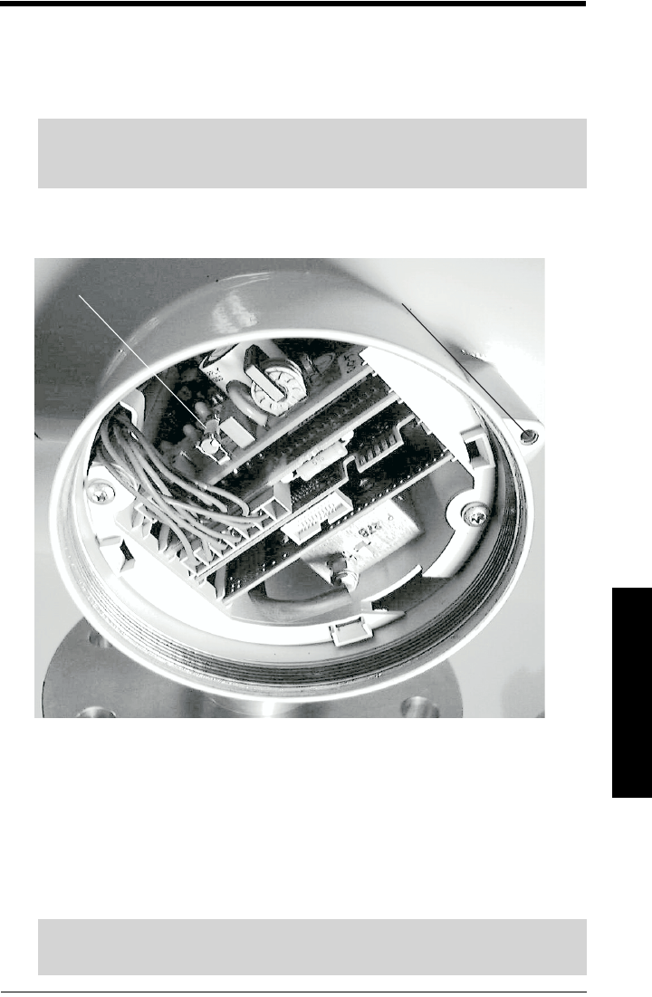
Changing the device fuse
The device fuse is located on the power supply unit board.
Position of device fuse and electronics cover locking:
Change a defective fuse as follows:
1. Disconnect the device from the power supply.
2. If your device is in a pressure-tight housing, release the cover locking of the
electronics cover with an Allen key (see above).
3. Remove the electronics cover from the housing.
4. If your device has an optional operating and monitoring module, pull it out of the
front of the housing. Disconnect the plug of its cable from the socket and place the
operating and monitoring module on one side.
Warning: The device fuse must only be changed by qualified personnel
who are familiar with the installation, commissioning, and operation of
the SITRANS LR 400.
device fuse
electronics cover locking
Caution! Take care not to bend or damage any of the cables.
Touching the electronic circuit boards can damage sensitive parts.
chap8.fm Page 65 Tuesday, October 9, 2001 1:29 PM

Page 66 Sitrans LR 400 – INSTRUCTION MANUAL 7ML19985FH01
mmmmm
Maintenance
5. Lift the device fuse carefully from its clip with a suitable tool (tweezers, flat-tipped
pliers or similar) (see above), and remove it from the housing.
6. Insert a new fuse. Only use original spare fuses! Press it into the clip until it snaps in
audibly.
7. Reassemble the device in reverse order.
Disconnecting the electronics part from the
mechanical part
For maintenance it is possible to separate the electronic enclosure of the device from the
mechanical part (flange) without endangering the pressure tightness of the vessel.
Release the threaded ring of the electronics part from the mechanical part with a hook
key 68/75 and remove the electronics part. Place the enclosed plastic cap on the
mechanical part to prevent from soiling.
Cleaning the antenna
Depending on the type of measuring material, it may be necessary to clean the antenna
at certain intervals to remove soiling which could affect the measuring result. You can
clean it without removing the flange from the vessel. Proceed as follows:
1. Disconnect and remove the electronics part as described above.
2. Unscrew the pressure window which becomes accessible after removing the
threaded ring with an M36 open-ended wrench and lift it off the mechanical part
together with the white PTFE stopper.
3. Clean the inside of the antenna with compressed air and/or a brush. Make
especially sure that the pressure window thread is clean. Apply fresh grease to the
thread as required. Check the O-rings for damage and replace them if necessary.
4. If the PTFE stopper has come loose when removing from the pressure window,
reinsert it long end first in the mechanical part. Push it into the guide up to its
thickened stop.
5. Place the pressure window and screw it tight.
6. Reattach the electronics part to the mechanical part. You can align the rotatable
housing head before tightening the threaded ring.
7. Check the pressure tightness of the vessel.
Caution! The device contains a second fuse that is not accessible via the front side.
This fuse is only to be replaced by the manufacturer (following a complete safety
check of the device).
Caution! As soon as you remove the pressure window from the mechanical part the
vessel is no longer pressure-tight and explosion protected!
chap8.fm Page 66 Tuesday, October 9, 2001 1:29 PM

7ML19985FH01 SITRANS LR 400 – INSTRUCTION MANUAL DRAFT Page 67
mmmmm
Certificates
Certificates
The necessary certificates are enclosed separately.
chap9.fm Page 67 Tuesday, October 9, 2001 1:13 PM

Page 68 Sitrans LR 400 – INSTRUCTION MANUAL DRAFT 7ML19985FH01
mmmmm
Glossary
Glossary
Term Explanation
Antenna offset Propagation time of the signal in the sensor, expressed as a dis-
tance
Current limit
The maximum possible value of the output signal in fault-free
operation in mA. The value of the fail signal may be above the
current limit with 24 mA.
Customer code User-defined code which protects the device against accidental
programming.
Dead band Value range below the device flange declared unmeasureable.
Echo movement
Sensor parameter for a fuzzy rule which takes into account
dynamic procedures in the measuring medium for example and
therefore rules out fixed targets.
Fixed target Permanently installed objects inside the vessel which may cause
reflective interference, e.g. struts, agitators, feed pipes etc.
FMCW method Frequency Modulated Continuous Wave method
Frequency deviation Changing the transmission frequency in the *FMCW method.
Level Distance from the *LRV to the surface of the *measuring
medium.
LRV Lower limit of the valid measuring range as a distance from the
bottom inside of the vessel.
Measuring medium The (solid or liquid) contents of the vessel.
Multiple echo
evaluation
Sensor parameter for a fuzzy rule which detects and suppresses
multiple reflections of the measuring signal at the vessel walls.
Nozzle height Distance from the top of the inside of the vessel to the bottom of
the device flange.
PELV Protected Extra Low Voltage
PTFE Polytetrafluorethylene (Teflon)
SELV Safety Extra Low Voltage
Signal-to-noise ratio Measure of the strength of reflection of the *measuring medium
in the current measuring situation in dB.
vessel height Distance between the floor and top of the vessel.
Triple reflector Metal instrument formed as a cubic segment with right angles.
URV Upper limit of the valid measuring range as a distance from the
bottom inside of the vessel.
Validity Measure of the certainty of the current measured value in %.
chap10.fm Page 68 Tuesday, October 9, 2001 1:51 PM

7ML19985FH01 SITRANS LR 400 – INSTRUCTION MANUAL DRAFT Page 69
mmmmm
Appendix 1
Appendix I
Alphabetical Parameter List
Parameter Name Menu
Identification
Number Page Number
Aging 3.1.1.4 28
Analog output 4.3 44
Antenna offset 4.6.9.6 51
Antenna type 4.6.5.4 49
Antenna&flange 4.6.5 49
AO select 4.3.1 44
Application type 4.2.2.1 34
Auto False Echo Suppression 4.2.3.9 39
Auto False Echo Suppression
Distance
4.2.3.A 39
Auto fix distance 4.2.3.6 38
Auto-Setup 1 25
Bottom design 4.2.5.8.2 44
Calculate 4.2.5.8 43
Calibrate 4.2.5.8.1 42
Calibrate/table 4.2.5.8 41
Clear table 4.2.5.8.4 43
Correction factor 4.2.2.4 35
Current limit 4.3.3 45
Current output 2.5 28
Customer code 5.2 52
Dead band 4.2.2.3 35
Descriptor 4.6.7 50
Device data 4 32
Device info 4.6 48
Device Revision 4.6.9.3 51
Device test 3.2 30
Diagnostics 3 28
Digital output 2.6 28
Digital output 4.4 46
Display 227
Display local 4.5.1.2 47
Display parameter 4.5 47
Display test 3.2.2 30
Echo amplitude 3.4.2 31
Echo motion 4.2.3.3 37
Electrical connection 4.6.3 49
Enter code 5.1 52
Enter table 4.2.5.8.2 42
Error signal 4.3.4 45
sitranslrd3.book Page 69 Tuesday, October 9, 2001 10:09 AM

Page 70 SITRANS LR 400 – INSTRUCTION MANUAL DRAFT 7ML19985FH01
mmmmm
Appendix 1
Factory reset 5.3 52
Failsafe level 4.2.2.7 36
Failsafe timer 4.2.2.8 36
Filling speed 4.2.2.5 35
Fix distance list 4.2.3.7 38
Flange material 4.6.5.6 50
Flange size 4.6.5.1 49
Flange temperature 4.6.2 48
Flange type 4.6.5.2 49
Function DO 4.4.1 46
Hardware revision 4.6.9.5 51
Hours > 85°C 3.1.1.5 28
HYST level 4.2.4.6 40
HYST volume 4.2.5.6 41
Language local 1.1 25
Language local 4.5.2 48
LCD lighting 4.5.3 48
Length unit 1.2 26
Length unit 4.1.1 32
Level 2.2 27
Level damping 1.7 27
Level damping 4.2.4.3 39
Level LRV 1.6 26
Level LRV 4.2.4.2 39
Level parameters 4.2.4 39
Level URV 1.5 26
Level URV 4.2.4.1 39
Line 1 local 4.5.1.1 47
Line 2 local 4.5.1.4 48
Manufacturer identification 4.6.9 50
Maximum temperature 3.1.1.2 28
MaxLim level 4.2.4.5 39
MaxLim Volume 4.2.5.5 41
Measuring conditions 4.2.2 34
Message 4.6.8 50
Minimum temperature 3.1.1.3 28
MinLim level 4.2.4.4 39
MinLim Volume 4.2.5.4 41
Multi-display 2.1 27
Multi-display 4.5.1 47
Multiple echo 4.2.3.2 37
Nozzle height 1.3 26
Nozzle height 4.2.1.1 33
Op era ting h ou rs 3.1.1.1 28
Operating Parameters 4.2 33
Options 5 52
Order no. 4.6.9.2 51
Parameter Name Menu
Identification
Number Page Number
sitranslrd3.book Page 70 Tuesday, October 9, 2001 10:09 AM

7ML19985FH01 SITRANS LR 400 – INSTRUCTION MANUAL DRAFT Page 71
mmmmm
Appendix 1
Other units 4.1.5 33
Pipe diameter (if 4.2.1.3 = yes) 4.2.1.3 34
Power supply 4.6.1 48
Pressure stage 4.6.5.3 49
Range Extension 4.2.2.9 36
Raw value 3.4.1 31
Reference distance 4.6.9.7 51
S/N ratio 3.4.3 31
Seal material 4.6.5.7 50
Self-test 3.2.1 30
Sensor damping 4.2.3.1 37
Sensor parameter 4.2.3 36
Sensor temperature 3.4.5 32
Sensor variables 3.4 31
Sensor, electronics, software,
application, parameters and or
service
3.1.x 29
Serial no. 4.6.9.1 50
Show table 4.2.5.8.3 44
Signal type DO 4.4.2 46
Simulate AO 3.3.1 30
Simulate DO 3.3.2 31
Simulation 3.3 30
Software revision 4.6.9.4 51
Status 3.1 28
Stilling pipe? 4.2.1.3 33
Surface 4.2.2.2 34
Tag 4.6.6 50
Tank characteristic 4.2.5.7 41
Tank design 4.2.5.8.1 43
Tank empty detection 4.2.3.5 38
Tank geometry 4.2.1 33
Tank height 1.4 26
Tank height 4.2.1.2 33
Tank height 4.2.5.8.4 44
Tank volume 4.2.5.8.3 44
Temperature unit 4.1.4 33
Units 4.1 32
Validity 3.4.4 32
Volume 2.3 27
Volume damping 4.2.5.3 40
Volume LRV 4.2.5.2 40
Volume Parameters 4.2.5 40
Volume unit 4.1.2 32
Volume URV 4.2.5.1 40
Wear 3.1.1 28
Window tracking 4.2.3.4 38
Parameter Name Menu
Identification
Number Page Number
sitranslrd3.book Page 71 Tuesday, October 9, 2001 10:09 AM

Page 72 SITRANS LR 400 – INSTRUCTION MANUAL DRAFT 7ML19985FH01
mmmmm
Appendix 1
sitranslrd3.book Page 72 Tuesday, October 9, 2001 10:09 AM

7ML19985FH01 SITRANS LR 400 – INSTRUCTION MANUAL DRAFT Page 73
mmmmm
Appendix II
Appendix II
Programming Chart
Menu
Identification
Number Parameter Name Value
1Auto-Setup
1.1 Language local
1.2 Length unit
1.3 Nozzle height
1.4 Tank height
1.5 Level URV
1.6 Level LRV
1.7 Level damping
2Display
2.1 Multi-display
2.2 Level
2.3 Volume
2.5 Current output
2.6 Digital output
3Diagnostics
3.1 Status
3.1.1 Wear
3.1.x Sensor, electronics, software, application,
parameters and or service
3.1.1.1 Operating hours
3.1.1.2 Maximum temperature
3.1.1.3 Minimum temperature
3.1.1.4 Aging
3.1.1.5 Hours > 85°C
3.2 Device test
3.2.1 Self-test
3.2.2 Display test
3.3 Simulation
3.3.1 Simulate AO
3.3.2 Simulate DO
3.4 Sensor variables
3.4.1 Raw value
3.4.2 Echo amplitude
3.4.3 S/N ratio
3.4.5 Sensor temperature
3.4.4 Validity
4Device data
4.1 Units
4.1.1 Length unit
4.1.2 Volume unit
sitranslrd3.book Page 73 Tuesday, October 9, 2001 10:09 AM

Page 74 SITRANS LR 400 – INSTRUCTION MANUAL DRAFT 7ML19985FH01
mmmmm
Appendix II
4.1.4 Temperature unit
4.1.5 Other units
4.2 Operating Parameters
4.2.1 Tank geometry
4.2.1.1 Nozzle height
4.2.1.2 Tank height
4.2.1.3 Stilling pipe?
4.2.1.3 Pipe diameter (if 4.2.1.3 = yes)
4.2.2 Measuring conditions
4.2.2.1 Application type
4.2.2.2 Surface
4.2.2.3 Dead band
4.2.2.4 Correction factor
4.2.2.5 Filling speed
4.2.2.7 Failsafe level
4.2.2.8 Failsafe timer
4.2.2.9 Range Extension
4.2.3 Sensor parameter
4.2.3.1 Sensor damping
4.2.3.2 Multiple echo
4.2.3.3 Echo motion
4.2.3.4 Window tracking
4.2.3.5 Tank empty detection
4.2.3.6 Auto fix distance
4.2.3.7 Fix distance list
4.2.3.9 Auto False Echo Suppression
4.2.3.A Auto False Echo Suppression Distance
4.2.4 Level parameters
4.2.4.1 Level URV
4.2.4.2 Level LRV
4.2.4.3 Level damping
4.2.4.4 MinLim level
4.2.4.5 MaxLim level
4.2.4.6 HYST level
4.2.5 Volume Parameters
4.2.5.1 Volume URV
4.2.5.2 Volume LRV
4.2.5.3 Volume damping
4.2.5.4 MinLim Volume
4.2.5.5 MaxLim Volume
4.2.5.6 HYST volume
4.2.5.7 Tank characteristic
4.2.5.8 Calibrate/table
4.2.5.8.1 Calibrate
4.2.5.8.2 Enter table
4.2.5.8.3 Show table
4.2.5.8.4 Clear table
Menu
Identification
Number Parameter Name Value
sitranslrd3.book Page 74 Tuesday, October 9, 2001 10:09 AM

7ML19985FH01 SITRANS LR 400 – INSTRUCTION MANUAL DRAFT Page 75
mmmmm
Appendix II
4.2.5.8 Calculate
4.2.5.8.1 Tank design
4.2.5.8.2 Bottom design
4.2.5.8.3 Tank volume
4.2.5.8.4 Tank height
4.3 Analog output
4.3.1 AO select
4.3.2 Volume parameter
4.3.2 Level parameter
4.3.3 Current limit
4.3.4 Error signal
4.4 Digital output
4.4.1 Function DO
4.4.2 Signal type DO
4.4.3 Volume parameter
4.4.3 Level parameter
4.5 Display parameter
4.5.1 Multi-display
4.5.1.1 Line 1 local
4.5.1.2 Display local
4.5.1.3 Volume parameter
4.5.1.3 Level parameter
4.5.1.4 Line 2 local
4.5.1.5 Volume parameter
4.5.1.5 Level parameter
4.5.2 Language local
4.5.3 LCD lighting
4.6 Device info
4.6.1 Power supply
4.6.2 Flange temperature
4.6.3 Explosion protection
4.6.4 Electrical connection
4.6.5 Antenna&flange
4.6.5.1 Flange size
4.6.5.2 Flange type
4.6.5.3 Pressure stage
4.6.5.4 Antenna type
4.6.5.6 Flange material
4.6.5.7 Seal material
4.6.6 Tag
4.6.7 Descriptor
4.6.8 Message
4.6.9 Manufacturer identification
4.6.9.1 Serial no.
4.6.9.2 Order no.
4.6.9.3 Device Revision
4.6.9.4 Software revision
Menu
Identification
Number Parameter Name Value
sitranslrd3.book Page 75 Tuesday, October 9, 2001 10:09 AM

Page 76 SITRANS LR 400 – INSTRUCTION MANUAL DRAFT 7ML19985FH01
mmmmm
Appendix II
4.6.9.5 Hardware revision
4.6.9.6 Antenna offset
4.6.9.7 Reference distance
5Options
5.1 Enter code
5.2 Customer code
5.3 Factory reset
Menu
Identification
Number Parameter Name Value
sitranslrd3.book Page 76 Tuesday, October 9, 2001 10:09 AM
7ML19985FH01 SITRANS LR 400 – INSTRUCTION MANUAL DRAFT Page 77
mmmmm
Appendix III
Appendix III
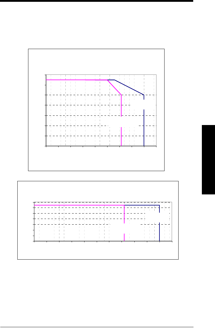
Ambient/Operating Temperature Specification
Maximum Flange and Process Temperature Versus Allowable
Ambient (Temperature Extension)
0
10
20
30
40
50
60
70
0 25 50 75 100 125 150 175 200 225 250 275
Process-Flange Temp Vs. Ambient
Ambient Temp. (C
)
Maximum Flange and Process Temperature
Versus Allowable Ambient
0
10
20
30
40
50
60
70
0 25 50 75 100 125 150 175 200 225
Process-Flange Temp Vs. Ambient
Ambient (C)
Process Flange
Temperature
Process
Tempe rat ure
Process Flange
Temperature
Process
Temperature
sitranslrd3.book Page 77 Tuesday, October 9, 2001 10:09 AM
Page 78 SITRANS LR 400 – INSTRUCTION MANUAL DRAFT 7ML19985FH01
mmmmm
Appendix IV
Appendix IV
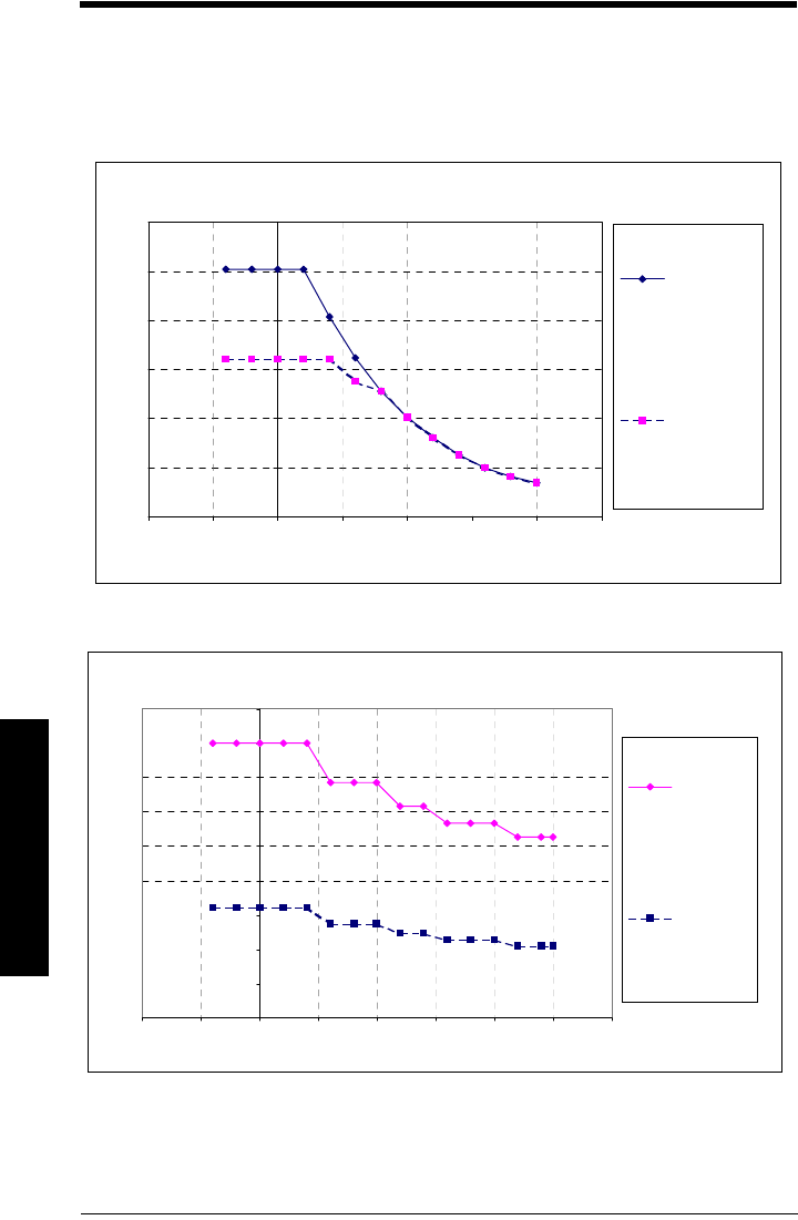
Process Pressure/Temperature de-Rating
* standard process seal is rated to a max. of 200°C of continuous duty.
*process seal for hazardous location is rate for a max of 290°C of continuous duty.
Flange 22482 or 22487, FF Standard Process Seal*
0.0
5.0
10.0
15.0
20.0
25.0
30.0
-100 -50 0 50 100 150 200 250
Temperature (°C)
Pressure (bar, gauge)
(A) 80 mm, 100
mm, 150 mm,
PN16 or 10K
(B) 80 mm , 100
mm, 150 mm
PN40
Flange 22482 or 22487, FF Process Seal for Hazardous Locations**
0.0
5.0
10.0
15.0
20.0
25.0
30.0
35.0
40.0
45.0
-100 -50 0 50 100 150 200 250 300
Temperature (°C)
Pressure (bar, gauge)
80 mm, 100
mm, 150 mm
PN16 or 10K
80 mm, 100
mm, 150 mm
PN40
chap14a.fm Page 78 Tuesday, October 9, 2001 1:42 PM
7ML19985FH01 SITRANS LR 400 – INSTRUCTION MANUAL DRAFT Page 79
mmmmm
Appendix IV
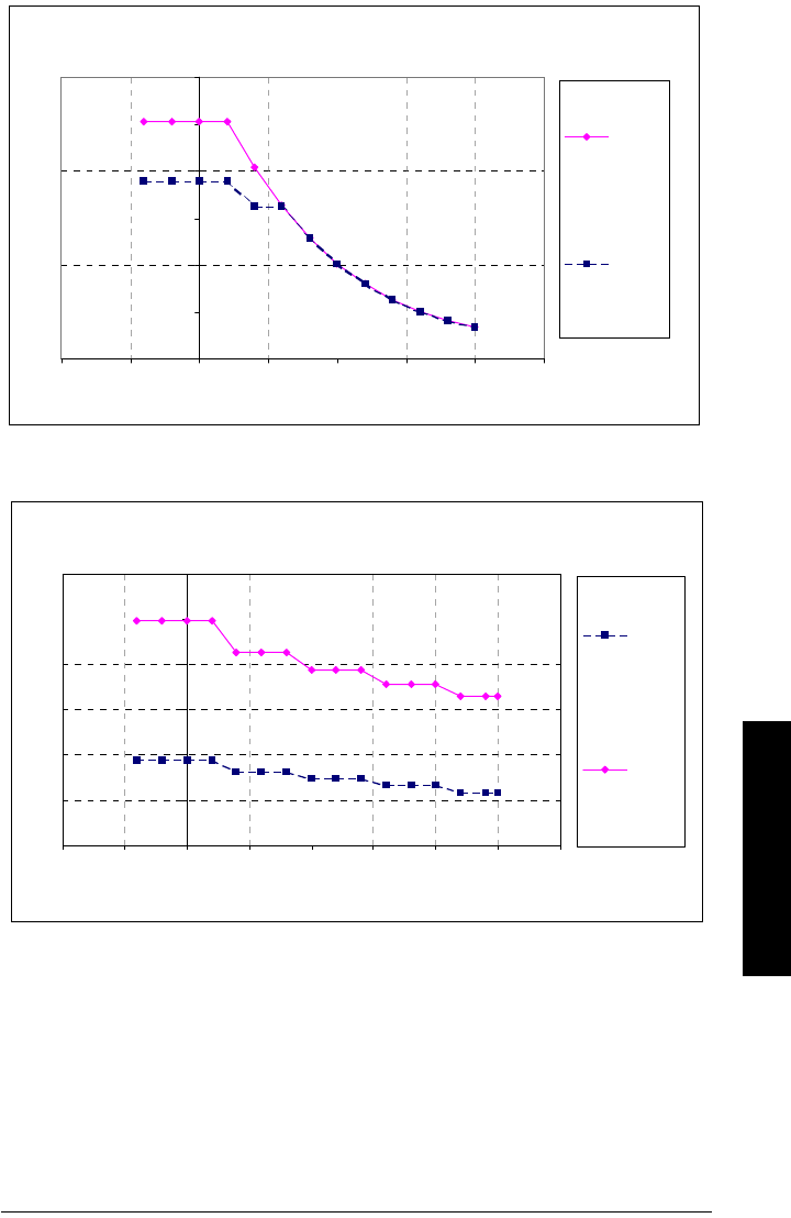
* standard process seal is rated to a max. of 200°C of continuous duty.
*process seal for hazardous location is rated to a max of 290°C of continuous duty.
Flange 22483 or 22488, FF Standard Process Seal*
0.0
5.0
10.0
15.0
20.0
25.0
30.0
-100 -50 0 50 100 150 200 250
Temperature (°C)
Pressure (bar, gauge)
3", 4", 6"
300 #
3", 4", 6"
150 #
Flange 22483 or 22488, RF Process Seal for Hazardous Locations**
0.0
10.0
20.0
30.0
40.0
50.0
60.0
-100 -50 0 50 100 150 200 250 300
Temperature (°C)
Pressure (bar, gauge)
3", 4",
6" 300 #
3", 4",
6" 150 #
chap14a.fm Page 79 Tuesday, October 9, 2001 1:42 PM

IQ300IX.fm Page 5 Tuesday, October 2, 2001 1:43 PM

c
*7ML19985FH01*