Siemens Canada Siemens Milltronics Process Instruments LR560 SITRANS LR560 Tank Level Probing Radar User Manual LT01 LR560PA
Siemens Canada Ltd. - Siemens Milltronics Process Instruments SITRANS LR560 Tank Level Probing Radar LT01 LR560PA
Contents
User Manual 2

Radar Transmitters
Operating Instructions 10/2010
SITRANS LR560 (PROFIBUS PA)
SITRANS
Draft_1.0-02
Firmware 1.00.00-32

© Siemens AG 2010
Safety Guidelines: Warning notices must be observed to ensure personal safety as well as that of
others, and to protect the product and the connected equipment. These warning notices are
accompanied by a clarification of the level of caution to be observed.
Qualified Personnel: This device/system may only be set up and operated in conjunction with this
manual. Qualified personnel are only authorized to install and operate this equipment in accordance with
established safety practices and standards.
Unit Repair and Excluded Liability:
• The user is responsible for all changes and repairs made to the device by the user or the user’s
agent.
• All new components are to be provided by Siemens Milltronics Process Instruments.
• Restrict repair to faulty components only.
• Do not reuse faulty components.
Warning: Cardboard shipping package provides limited humidity and moisture protection. This product
can only function properly and safely if it is correctly transported, stored, installed, set up, operated, and
maintained.
This product is intended for use in industrial areas. Operation of this equipment in a residential area
may cause interference to several frequency based communications.
Note: Always use product in accordance with specifications.
Copyright Siemens AG 2010. All Rights
Reserved
Disclaimer of Liability
This document is available in bound version and in
electronic version. We encourage users to purchase
authorized bound manuals, or to view electronic
versions as designed and authored by Siemens
Milltronics Process Instruments. Siemens Milltronics
Process Instruments will not be responsible for the
contents of partial or whole reproductions of either
bound or electronic versions.
While we have verified the contents of this
manual for agreement with the
instrumentation described, variations remain
possible. Thus we cannot guarantee full
agreement. The contents of this manual are
regularly reviewed and corrections are
included in subsequent editions. We welcome
all suggestions for improvement.
Technical data subject to change.
MILLTRONICS®is a registered trademark of Siemens Milltronics Process Instruments.
Contact SMPI Technical Publications European Authorized Representative
at the following address:
Technical Publications Siemens AG
Siemens AG Industry Sector
Siemens Milltronics Process Instruments 76181 Karlsruhe
1954 Technology Drive, P.O. Box 4225 Deutschland
Peterborough, Ontario, Canada, K9J 7B1
Email: techpubs.smpi@siemens.com
• For a selection of Siemens Milltronics level measurement manuals, go to:
www. siemens.com/processautomation. Under Process Instrumentation, select
Level
Measurement
and then go to the manual archive listed under the product family.
• For a selection of Siemens Milltronics weighing manuals, go to:
www. siemens.com/processautomation. Under Weighing Technology, select
Continuous
Weighing Systems
and then go to the manual archive listed under the product family.

i
mmmmm
Table of Contents
Table of Contents
Safety Notes .............................................................................................................................................1
Safety marking symbols ..............................................................................................................1
FCC Conformity ........................................................................................................................................1
CE Electromagnetic Compatibility (EMC) Conformity ....................................................................2
Industry Canada ......................................................................................................................................2
The Manual ...............................................................................................................................................3
Application Example .....................................................................................................................3
Technical Support ....................................................................................................................................3
Abbreviations and Identifications .......................................................................................................4
SITRANS LR560 Overview .................................................................................................6
Programming ............................................................................................................................................6
Local Display Interface (LDI) ......................................................................................................7
Versions .....................................................................................................................................................7
Applications ..............................................................................................................................................7
Approvals and Certificates ...................................................................................................................7
Specifications ......................................................................................................................8
Power............................................................................................................................................. 8
Performance................................................................................................................................. 8
Interface ........................................................................................................................................ 9
Mechanical................................................................................................................................... 9
Environmental ............................................................................................................................ 10
Process........................................................................................................................................ 10
Approvals.................................................................................................................................... 10
Programmer (infrared keypad) .............................................................................................. 11
Dimensions .............................................................................................................................................12
Installation ......................................................................................................................... 17
Pressure Equipment Directive, PED, 97/23/EC ...............................................................................17
Mounting location .................................................................................................................................18
Nozzle location .............................................................................................................................18
Aimer Adjustment .......................................................................................................................19
Air Purging System ...............................................................................................................................20
Purge Connection ........................................................................................................................21
Removable Display ...............................................................................................................................22
Wiring ..................................................................................................................................23
Power .......................................................................................................................................................23
Connecting SITRANS LR560 ...............................................................................................................23
Basic PLC configuration with PROFIBUS PA ........................................................................24
Wiring setups for hazardous area installations ..................................................................25
Instructions Specific to Hazardous Area Installations ...............................................................26
Local Operation .................................................................................................................28
Activating SITRANS LR560 .................................................................................................................28
The LCD Display ...................................................................................................29
Handheld Programmer ...............................................................................................................30
Programming SITRANS LR560 .................................................................................................31
Quick Start Wizard via the LDI push buttons .................................................................................34
Quick Start Wizard via the handheld programmer .......................................................................34
Requesting an Echo Profile ................................................................................................................37

ii
mmmmm
Table of Cotents
Device Address ......................................................................................................................................37
Level application example ...................................................................................................................38
Operating via SIMATIC PDM ..........................................................................................39
Functions in SIMATIC PDM ................................................................................................................39
SIMATIC PDM Version .........................................................................................................................39
Electronic Device Description (EDD) ......................................................................................39
Configuring a new device .........................................................................................................40
Set Address ...................................................................................................................................40
Quick Start Wizard via SIMATIC PDM .............................................................................................40
Quick Start .....................................................................................................................................41
Changing parameter settings using SIMATIC PDM .....................................................................44
Parameters accessed via pull-down menus ........................................................................44
Diagnostics ...................................................................................................................................56
Security ..........................................................................................................................................59
Operating via FDT (Field Device Tool) ...........................................................................61
Device Type Manager (DTM) .............................................................................................................61
SITRANS DTM .......................................................................................................................................61
The instrument EDD ..............................................................................................................................61
Configuring a new device via FDT ....................................................................................................61
Parameter Reference .......................................................................................................62
Quick Start .................................................................................................................................. 62
Quick Start Wizard.......................................................................................................... 62
AFES (Auto False Echo Suppression) Wizard .......................................................... 63
Copy Parameters to Display......................................................................................... 64
Copy Parameters from Display.................................................................................... 64
Copy Firmware to Display ............................................................................................. 64
Copy Firmware from Display ........................................................................................ 65
Setup ............................................................................................................................................ 65
Identification..................................................................................................................... 65
Device ................................................................................................................................ 65
Sensor................................................................................................................................ 66
Signal Processing............................................................................................................ 69
AIFB1.................................................................................................................................. 77
AIFB2.................................................................................................................................. 81
Measured Values............................................................................................................ 81
Filtering .............................................................................................................................. 81
Diagnostics................................................................................................................................. 82
Echo Profile....................................................................................................................... 82
Fault Reset ........................................................................................................................ 82
Trend .................................................................................................................................. 83
Electronics Temperature............................................................................................... 83
Condensed Status........................................................................................................... 83
Allocation .......................................................................................................................... 84
Peak Values...................................................................................................................... 86
Service ........................................................................................................................................ 86
Demo Mode...................................................................................................................... 86
Master Reset.................................................................................................................... 87
Powered Hours................................................................................................................ 87
Power-on Resets............................................................................................................. 88
LCD Backlight................................................................................................................... 88

iii
mmmmm
Table of Contents
LCD Contrast..................................................................................................................... 88
Remaining Device Lifetime ........................................................................................... 88
Remaining Sensor Lifetime........................................................................................... 91
Service Schedule ............................................................................................................ 94
Calibration Schedule ...................................................................................................... 97
Communication....................................................................................................................... 100
Device Address ............................................................................................................ 100
PROFIBUS Ident Number ........................................................................................... 101
Security..................................................................................................................................... 101
Remote Access............................................................................................................. 101
Local Access ................................................................................................................. 101
Language.................................................................................................................................. 101
Appendix A: Alphabetical Parameter List .................................................................. 103
Appendix B: Troubleshooting ....................................................................................... 106
Communication Troubleshooting ................................................................................................... 106
Device Status Icons ........................................................................................................................... 107
General Fault Codes .......................................................................................................................... 108
Operation Troubleshooting ...............................................................................................................112
Appendix C: Maintenance ............................................................................................ 114
Unit Repair and Excluded Liability ..................................................................................................114
Appendix D: Technical Reference ............................................................................... 115
Principles of Operation ......................................................................................................................115
Process Variables ......................................................................................................................115
Echo Processing ..................................................................................................................................115
Process Intelligence .................................................................................................................115
Echo Selection ...........................................................................................................................116
Measurement Range ................................................................................................................120
Measurement Response ...................................................................................................................120
Damping .................................................................................................................................................121
Loss of Echo (LOE) ...............................................................................................................................121
LOE Timer ....................................................................................................................................121
Fail-safe Behavior .....................................................................................................................122
Temperature derating curve ............................................................................................................123
Appendix E: PROFIBUS PA Profile Structure ............................................................. 124
PROFIBUS Level Device Design ......................................................................................................124
Block Model ..........................................................................................................................................124
Description of the blocks .........................................................................................................125
Appendix F: Communications via PROFIBUS PA ...................................................... 129
Device Configuration tool ..................................................................................................................129
SIMATIC PDM ............................................................................................................................129
Network Configuration ......................................................................................................................129
The GSD file ................................................................................................................................129
Bus Termination ...................................................................................................................................129
Power Demands ..................................................................................................................................129
PROFIBUS address .............................................................................................................................130
Operating as a Profile Device ...........................................................................................................130
Configuring a device .................................................................................................................131
Configuring PROFIBUS PA with an S7-300/ 400 PLC ........................................................131
Cyclic versus Acyclic Data ................................................................................................................131

iv
mmmmm
Table of Cotents
Cyclic Data ..................................................................................................................................131
Status Byte ...........................................................................................................................................132
Condensed Status .....................................................................................................................132
Status Byte .................................................................................................................................134
Diagnostics ...........................................................................................................................................135
Diagnosis reply (available cyclically) ....................................................................................135
Diagnosis Object (available cyclically or acyclically) .......................................................136
Acyclic Extended Diagnostics (General Fault Codes) ......................................................138
Acyclic Data ..........................................................................................................................................141
Appendix G: Firmware Revision History .................................................................... 142
Glossary ............................................................................................................................ 143
Index .................................................................................................................................. 147
LCD menu structure ....................................................................................................... 151
7ML19985LT01 SITRANS LR560 (PROFIBUS PA) – OPERATING INSTRUCTIONS Page 1
mmmmm
SITRANS LR560
Safety Notes
Special attention must be paid to warnings and notes highlighted from the rest of the text
by grey boxes.
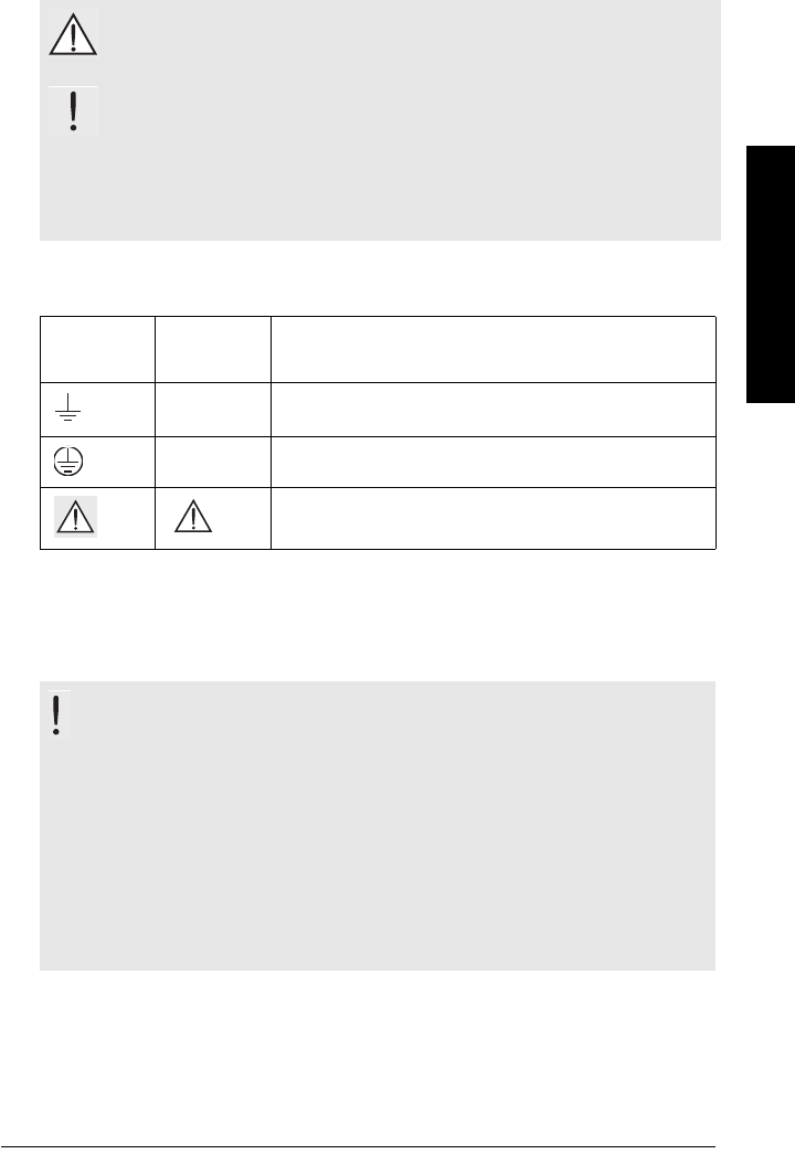
Safety marking symbols
FCC Conformity
US Installations only: Federal Communications Commission (FCC) rules
WARNING symbol relates to a caution symbol on the product, and
means that failure to observe the necessary precautions can result
in death, serious injury, and/or considerable material damage.
WARNING symbol, used when there is no corresponding caution
symbol on the product, means that failure to observe the necessary
precautions can result in death, serious injury, and/or considerable
material damage.
Note: means important information about the product or that part of the operating
manual.
In manual On
product Description
Earth (ground) Terminal
Protective Conductor Terminal
(Label on product: yellow background.) WARNING: refer
to accompanying documents (manual) for details.
WARNING: Changes or modifications not expressly approved by
Siemens Milltronics could void the user’s authority to operate the
equipment.
Notes:
• This equipment has been tested and found to comply with the limits for a Class B
digital device, pursuant to Part 15 of the FCC Rules. These limits are designed to
provide reasonable protection against harmful interference when the equipment is
operated in a commercial environment.
• This equipment generates, uses, and can radiate radio frequency energy and, if not
installed and used in accordance with the instruction manual, may cause harmful
interference to radio communications.

Page 2 SITRANS LR560 (PROFIBUS PA) – OPERATING INSTRUCTIONS 7ML19985LT01
mmmmm
SITRANS LR560
CE Electromagnetic Compatibility (EMC) Conformity
This equipment has been tested and found to comply with the following EMC Standards:
Industry Canada
a) Operation is subject to the following two conditions: (1) this device may not cause
interference, and (2) this device must accept any interference, including
interference that may cause undesired operation of the device.
b) This device shall be installed and operated in a completely enclosed container to
prevent RF emission which otherwise can interfere with aeronautical navigation.
Installation shall be done by trained installers, in strict compliance with the
manufacturer’s instructions.
c) The use of this device is on a “no-interference, no-protection” basis. That is, the
user shall accept operations of high-powered radar in the same frequency band
which may interfere with or damage this device. On the other hand, level probing
devices found to interfere with primary licensing operations will be required to be
removed at the user’s expense.
EMC Standard Title
CISPR 11:2004/EN
55011:1998+A1:1999&A2:2002, CLASS B
Limits and methods of measurements of radio
disturbance characteristics of industrial, scientific,
and medical (ISM) radio-frequency equipment.
EN 61326:1997+A1:1998+A2:2001+A3:2003
(IEC 61326:2002)
Electrical Equipment for Measurement, Control and
Laboratory Use – Electromagnetic Compatibility.
EN61000-4-2:2001
Electromagnetic Compatibility (EMC) Part 4-2:Testing
and measurement techniques – Electrostatic
discharge immunity test.
EN61000-4-3:2002
Electromagnetic Compatibility (EMC) Part 4-3:
Testing and measurement techniques – Radiated,
radio-frequency, electromagnetic field immunity test.
EN61000-4-4:2004
Electromagnetic Compatibility (EMC) Part 4-4:
Testing and measurement techniques – Electrical
fast transient/burst immunity test.
EN61000-4-5:2001
Electromagnetic Compatibility (EMC) Part 4-5:
Testing and measurement techniques – Surge
immunity test.
EN61000-4-6:2004
Electromagnetic Compatibility (EMC) Part 4-6:
Testing and measurement techniques – Immunity to
conducted disturbances, induced by radio-frequency
fields.
EN61000-4-8:2001
Electromagnetic Compatibility (EMC) Part 4-8:
Testing and measurement techniques – Power
frequency magnetic field immunity test.

7ML19985LT01 SITRANS LR560 (PROFIBUS PA) – OPERATING INSTRUCTIONS Page 3
mmmmm
SITRANS LR560
d) This level probing device is only permitted for installation inside enclosed
containers. The installer/user of this device shall ensure that it is at least 10 km from
the Penticton radio astronomy station (British Columbia latitude: 49° 19' 12" N,
longitude: 119° 37'12" W). For devices not meeting this 10 km separation (e.g. the
Okanagan Valley, British Columbia) the installer/ user must coordinate with and
obtain the written concurrence of the Director of the Penticton radio astronomy
station before the equipment can be installed or operated. The Penticton contact is
Tel: 250-493-2277/ fax: 250-493-7767. (In case of difficulty, the Manager, Radio
Equipment Standards, Industry Canada, may also be contacted.)
The Manual
This manual will help you set up your SITRANS LR560 for optimum performance. We
always welcome suggestions and comments about manual content, design, and
accessibility. Please direct your comments to techpubs.smpi@siemens.com.
For other Siemens Milltronics level measurement manuals, go to:
www.siemens.com/level, and look under Level Measurement.
Application Example
The application example used in this manual illustrates a typical installation using
SITRANS LR560. (See
Level application example
on page 38.) Because there is often a
range of ways to approach an application, other configurations may also apply.
In all examples, substitute your own application details. If the example does not apply to
your application, check the applicable parameter reference for the available options.
Technical Support
Support is available 24 hours a day.
To find your local Siemens Automation Office address, phone number and fax number go
to: www.siemens.com/automation/partner
• Click on the tab Contact, select Service, then click Service again to find your
product group (+Automation Technology > +Sensor Systems >+Process
Instrumentation > +Level Measurement > +Continous). Select Radar.
• Select the country followed by the City/Region.
• Select Technical Support under Service.
Notes:
• This product is intended for use in industrial areas. Operation of this equipment in a
residential area may cause interference to several frequency based
communications.
• Please follow the installation and operating procedures for a quick, trouble-free
installation and to ensure the maximum accuracy and reliability of your SITRANS LR560.
• This manual applies to the SITRANS LR560 (PROFIBUS PA) only.

Page 4 SITRANS LR560 (PROFIBUS PA) – OPERATING INSTRUCTIONS 7ML19985LT01
mmmmm
SITRANS LR560
For on-line technical support go to: www.siemens.com/automation/support-request
• Enter the device name (SITRANS LR560) or order number, then click on Search,
and select the appropriate product type. Click on Next.
• You will be prompted to enter a keyword describing your issue. Then either
browse the relevant documentation, or click on Next to email a detailed
description of your issue to Siemens Technical Support staff.
Siemens IA/DT Technical Support Center: phone +49 (0)911 895 7 222
Abbreviations and Identifications
Short
form Long Form Description Units
AIFB Analog Input Function Block
CE / FM
/ CSA
Conformité Européenne /
Factory Mutual / Canadian
Standards Association
safety approval
DCS Distributed Control System control room apparatus
dK dielectric constant
EDD Electronic Device Description
ESD Electrostatic Discharge
FMCW Frequency Modulated
Continuous Wave radar principle
IiInput current mA
IoOutput current mA
LCD Liquid Crystal Display
LDI Local Display Interface removable display with push
buttons
LUI Local User Interface
view outputs via LCD display;
make modifications via push
buttons or handheld programmer
μs microsecond 10-6 Second
PA Process Automation
(PROFIBUS)
PED Pressure Equipment Directive safety approval
ppm parts per million
PV Primary Value measured value

7ML19985LT01 SITRANS LR560 (PROFIBUS PA) – OPERATING INSTRUCTIONS Page 5
mmmmm
SITRANS LR560
SELV Safety extra low voltage
SV Secondary Value equivalent value
TB Transducer Block
TVT Time Varying Threshold sensitivity threshold
UiInput voltage V
UoOutput voltage V
Short
form Long Form Description Units
(cont’d
Page 6 SITRANS LR560 (PROFIBUS PA) – OPERATING INSTRUCTIONS 7ML19985LT01
mmmmm
SITRANS LR560
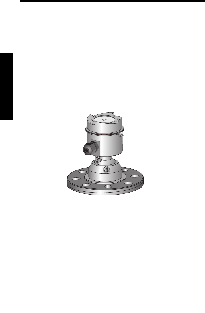
SITRANS LR560 Overview
SITRANS LR560 is a 2-wire, 78 GHz FMCW radar level transmitter for continuous
monitoring of solids in vessels to a range of 100 m (329 ft). The plug and play performance
is ideal for all solids applications, including those with extreme dust and high
temperatures to +200 °C (+392 °F). The device consists of an electronic circuit coupled to
a lens antenna and flange for quick and easy positioning.
The main benefits of using 78 GHz over devices using lower frequency are:
• very narrow beam, so device is insensitive to mounting nozzle interference and
vessel obstructions.
• short wavelength yields very good reflection properties on sloped solids, so aiming
towards material angle of repose is usually not necessary.
The technology is very tolerant of buildup on the lens antenna, however an air purge inlet
is provided for periodic cleaning if required.
SITRANS LR560 supports PROFIBUS PA communication protocol, and SIMATIC PDM
software. Signals are processed using Process Intelligence which has been field-proven
in over 1,000,000 applications worldwide (ultrasonic and radar). This device supports
acyclic communications from both a PROFIBUS Class I and Class II master.
Programming
SITRANS LR560 is very easy to install and configure via an optional graphical local
display interface. You can modify the built-in parameters either locally via the push
buttons or using the infrared handheld programmer, or from a remote location using one
of the following options:
• PROFIBUS PA (using SIMATIC PDM, FDT [such as PACTware or Fieldcare])
• HART (using 375 handheld Field Communicator, SIMATIC PDM, AMS, FDT [such as
PACTware or Fieldcare]). See SITRANS LR560 (mA/HART) Instruction Manual for
more information.
• Foundation Fieldbus FF (using 375 handheld Field Communicator or AMS). See
SITRANS LR560 (Foundation Fieldbus) Instruction Manual for more information.
Once programmed, the graphic Local Display Interface (LDI) can be removed and used to
transfer parameters to multiple SITRANS LR560s.

7ML19985LT01 SITRANS LR560 (PROFIBUS PA) – OPERATING INSTRUCTIONS Page 7
mmmmm
SITRANS LR560
Local Display Interface (LDI)
• LDI may be ordered installed or added later as an
option
• can be mounted in 1 of 4 positions at 90 degree
intervals, for easy viewing after installation
• displays level and diagnostic information
including echo profile and trend over time
• backlit for easy viewing in dimly lit areas
• allows you to copy parameters from one device to
another
• provides high speed firmware transfer capabilities for future upgrades
Versions
Two different versions of the LR560 are available:
• 40 m range, 100 °C maximum process temperature
• 100 m range, 200 °C maximum process temperature
Applications
• solids bulk storage vessels
• cement powder, plastic powder/pellets, grain, flour, coal, and other applications
Approvals and Certificates
SITRANS LR560 is available with General Purpose or Hazardous approvals.
.
Application
Type Approval Rating Valid for: Wiring
Non-
hazardous
General
Purpose CSAUS/C, FM, CE, C-TICK N. America,
Europe
See
page 23
Hazardous
Non-Sparking/
Energy Limited ATEX II 3G Ex nA/nL IIC T4 Gc Europe See
page 25
Dust Ignition
Proof
ATEX II 1D, 1/2D, 2D
IECEx SIR 09.0149X
Ex ta IIIC T139 oC
Europe and
International
See
page 25
FM/CSA:
Class II, Div. 1, Groups E, F, G
Class III T4
US/Canada See
page 26
Non-incendive FM/CSA:
Class I, Div. 2, Groups A, B, C, D T4 US/Canada See
page 26

Page 8 SITRANS LR560 (PROFIBUS PA) – OPERATING INSTRUCTIONS 7ML19985LT01
mmmmm
Specifications
Specifications
Power
Bus powered 9 to 32 V DC, per IEC 61158-2 (PROFIBUS PA)
Current consumed 13.5 mA
Performance
Reference operating conditions according to IEC 60770-1
• ambient temperature +15 to +25 °C (+59 to +77 °F)
• humidity 45% to 75% relative humidity
• ambient pressure 860 to 1060 mbar g (86,000 to 106,000 N/m2 g)
Measurement Accuracy1) (measured in accordance with IEC 60770-1)
• Maximum measured error - Greater of 25 mm (1") or 0.25 % of range from
minimum detectable distance to full range
Frequency 78 to 79 GHz FMCW
Max. measurement range2)
• 40 m version 40 m (1.31 ft)
• 100 m version 100 m (328 ft)
Min. detectable distance 300 mm (11.8") from sensor reference point
Update time3) maximum 10 seconds, depending on setting for
Response Rate (2.3.6.1.)
Influence of ambient temperature <0.003%/K (average over full temperature range,
referenced to maximum range)
Dielectric constant of material measured
• for ranges up to 20 m (65.6 ft) minimum dK = 1.6
• for ranges up to 100 m (328 ft) minimum dK = 2.5
Memory
• non-volatile EEPROM
• no battery required.
Note: Siemens Milltronics makes every attempt to ensure the accuracy of these
specifications but reserves the right to change them at any time.
1) Reference conditions: Position Detect (2.4.5.2.) set to Center and Algorithm (2.4.5.1.)
set to True First Echo.
2) From sensor reference point, see
Dimensions
on page 12.
3) Reference conditions: Response Rate (2.3.6.1.) set to FAST.

7ML19985LT01 SITRANS LR560 (PROFIBUS PA) – OPERATING INSTRUCTIONS Page 9
mmmmm
Specifications
Interface
Communication
• PROFIBUS PA 3.01
Configuration
• remote Siemens SIMATIC PDM or FDT such as PACTWARE
• local Siemens infrared handheld programmer or local
control buttons
Optional removable graphic LCD, with bar graph representing level
local display interface (LDI)1)
Mechanical
Process Connections:
• universal flat-faced flanges2)
3"/80 mm, 4"/100 mm, 6"/150 mm
- materials stainless steel 316L (1.4404 or 1.4435), or 304
• Aimer flanges2)
3"/80 mm, 4"/100 mm, 6"/150 mm
- material polyurethane powder-coated cast aluminum
Enclosure
• construction 316L/1.4404 stainless steel
• conduit entry M20x1.5, or ½" NPT
• conduit entry connector M12 connector (shipped with M20 to M12 adaptor)
(optional) or 7/8" connector (shipped with 1/2" NPT to 7/8"
adaptor)
• ingress protection Type 4X/NEMA 4X, Type 6/NEMA 6, IP68
• lid with window polycarbonate (window material)
Lens antenna material
•construction
- 40 m version PEI
- 100 m version PEEK
Air Purge Connection
• equipped with female 1/8" NPT fitting
Weight
• 3" stainless steel flange model 3.15 kg (6.94 lb)
1) Display quality will be degraded in temperatures below –20 °C (–4 °F) and above +65
°C (+149 °F).
2) Universal flange mates with EN 1092-1 (PN16)/ASME B16.5 (150 lb)/JIS 2220 (10K) bolt
hole pattern.

Page 10 SITRANS LR560 (PROFIBUS PA) – OPERATING INSTRUCTIONS 7ML19985LT01
mmmmm
Specifications
Environmental
• location indoor/ outdoor
• altitude 5000 m (16,404 ft) max.
• ambient temperature −40 to +80 °C (−40 to +176 °F)
• relative humidity suitable for outdoor
Type 4, 4X/NEMA 4, 4X, Type 6/NEMA 6, IP68
enclosure (see note above)
• installation category I
• pollution degree 4
Process
• temperature and pressure1)
Approvals
•General CSA
US/C, FM, CE, C-TICK
• Radio R&TTE (Europe), FCC, Industry Canada,
• Hazardous
Non-sparking/
Energy Limited2) (Europe) ATEX II 3G Ex nA/nL IIC T4 Gc
Dust Ignition Proof 2)(Europe/International) ATEX II 1D, 1/2D, 2D
IECEx SIR 09.0149X
Ex ta IIIC T139 oC
Note: Use appropriate conduit seals to maintain IP or NEMA rating.
Versions Stainless
steel flange
Aimer flange
0.5 bar max.
Aimer flange
3.0 bar max
40 m –40 to +100 °C
(–40 to +212 °F)
–40 to +100 °C
(–40 to +212 °F)
–40 to +100 °C
(–40 to +212 °F)
100 m –40 to +200 °C
(–40 to +392 °F)
–40 to +200 °C
(–40 to +392 °F)
–40 to +120 °C
(–40 to +248 °F)
1) Maximum and minimum temperatures are dependent on the process connection,
antenna and O-ring materials. Use of the Easy Aimer limits maximum temperature.
Note: The device label lists the approvals that apply to your device.
2) See
Non-Sparking/Energy Limited wiring (Europe) and Dust Ignition Proof wiring
(Europe/International)
on page 25 for more details.

7ML19985LT01 SITRANS LR560 (PROFIBUS PA) – OPERATING INSTRUCTIONS Page 11
mmmmm
Specifications
Dust Ignition Proof 1) (US/Canada) FM/CSA:
Class II, Div. 1, Groups E, F, G
Class III T4
Non-incendive1) (US/Canada) FM/CSA Class I, Div. 2,
Groups A, B, C, D, T4
Programmer (infrared keypad)
Siemens Milltronics Infrared IS (Intrinsically Safe) Hand Programmer for hazardous and
all other locations (battery is non-replaceable)
• approval FM/CSA Class I, II, III, Div. 1, Gr. A to G T6
CE
ATEX II 1GD Ex ia IIC T4 Ga
Ex iaD 20 T135 °C
IECEx SIR 09.0073 Ex ia IIC T4 Ga
Ex iaD 20 T135 °C
INMETRO Br-Ex ia IIC T4
• ambient temperature −20 to +50 °C (−5 to +122 °F)
• interface proprietary infrared pulse signal
• power 3 V lithium battery
• weight 150 g (0.3 lb)
• color black
• Part Number 7ML1930-1BK
1) See
Non-incendive and Dust Ignition Proof wiring (US/Canada)
on page 26.
Notes:
• Battery is non-replaceable with a lifetime expectancy of 10 years in normal use.
• To estimate the lifetime expectancy, check the nameplate on the back for the serial
number. The first six numbers show the production date (mmddyy), for example,
serial number 032608101V.
Page 12 SITRANS LR560 (PROFIBUS PA) – OPERATING INSTRUCTIONS 7ML19985LT01
mmmmm
Specifications
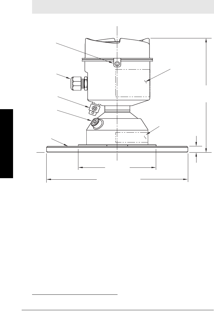
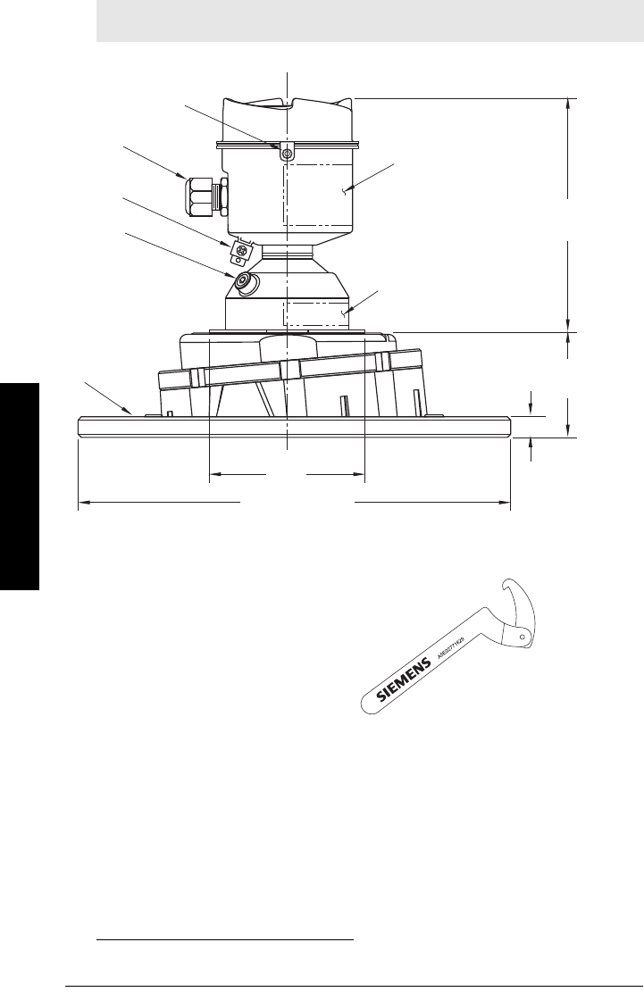
Dimensions
SITRANS LR560 with stainless steel Universal Flat-faced Flange
1)
Note: Refer to
Universal Slotted Flange
on page 16 for bolt hole patterns and
dimensions.
1) Shipped with product, packed in a separate bag.
grounding
lug
purge
inlet
process connection:
flange
cable gland1)
110 mm
(4.33")
176 mm
(6.93")
9.6 mm
(0.38")
3": 200 mm (7.87")
4": 229 mm (9.02")
6": 285 mm (11.22")
sensor
ref.
point
lid lock
pressure/
temperature
related
information
device
label
7ML19985LT01 SITRANS LR560 (PROFIBUS PA) – OPERATING INSTRUCTIONS Page 13
mmmmm
Specifications
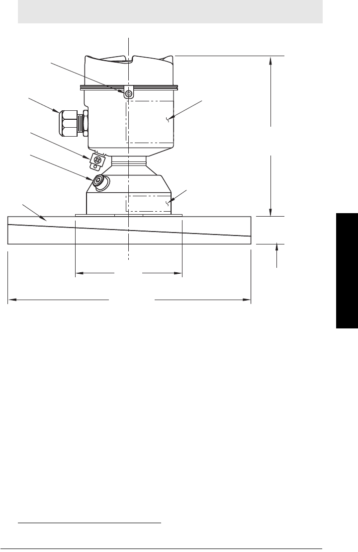
SITRANS LR560 with 3" Aimer Flange
1)
Note: Refer to
Universal Slotted Flange
on page 16 for bolt hole patterns and
dimensions.
1) Shipped with product, packed in a separate bag.
grounding
lug
purge
inlet
process
connection:
aimer flange
cable
gland1)
110 mm
(4.33")
166.1 mm
(6.54")
200 mm
(7.87")
23.3 mm
(0.92"
sensor
reference
point
lid lock
pressure/
temperature
related
information
device
label
Page 14 SITRANS LR560 (PROFIBUS PA) – OPERATING INSTRUCTIONS 7ML19985LT01
mmmmm
Specifications
SITRANS LR560 with 4" and 6" Aimer Flange
1)
C Spanner
Note: Refer to
Universal Slotted Flange
on page 16 for bolt hole patterns and
dimensions.
1) Shipped with product, packed in a separate bag.
grounding
lug
purge
inlet
process
connection:
aimer flange
cable
gland1)
110 mm
(4.33")
166.1 mm
(6.54")
4": 229 mm (9.02")
6": 285 mm (11.22")
9.6 mm
(0.38")
sensor
reference
point
4": 53.2 mm (2.09")
6": 60.0 mm (2.36")
lid lock
pressure/
temperature
related
information
device
label
A C spanner, used to loosen the aimer
locking ring, is shipped with the device.

7ML19985LT01 SITRANS LR560 (PROFIBUS PA) – OPERATING INSTRUCTIONS Page 15
mmmmm
Specifications
Process Connection Label (Pressure Rated Versions)
For pressure-rated versions only, the process connection label lists the following
information:
Item Sample Text Comments/Explanation
CONNECTION SERIES ASME B16.5 / EN 1092-1
/ JIS B 2220
Flange Series: dimensional pattern based on
ASME B16.5/EN 1092-1/JIS B 2220 flange
standards
NOM. PIPE SIZE (DN) 4 INCH / 100mm Nominal Pipe Size: based on 150#/PN16/10K
flange pressure classes
MAWP (PS) 3BAR Maximum Allowable Working Pressure at
Design Temperature
DESIGN TEMP. (TS) 100 ºC Maximum Allowable Working Temperature
MIN. PROCESS 3BAR AT -40 ºC Minimum Wetted Process Conditions
0F13589.5 Canadian Registration Number (CRN)
TEST PRESSURE (PT) 5.2 BAR Production Test Pressure
TEST DATE 10/01/04 Date of Pressure Test (Year/Month/Day)
PROCESS SERIES 25785 Pressure Tag Family Series
WETTED NON-METALLIC PEI Sensor Lens Material
WETTED METALLICS 304L Process Connection Material(s)
WETTED SEALS FKM / VQM Seal Material(s)
Page 16 SITRANS LR560 (PROFIBUS PA) – OPERATING INSTRUCTIONS 7ML19985LT01
mmmmm
Specifications
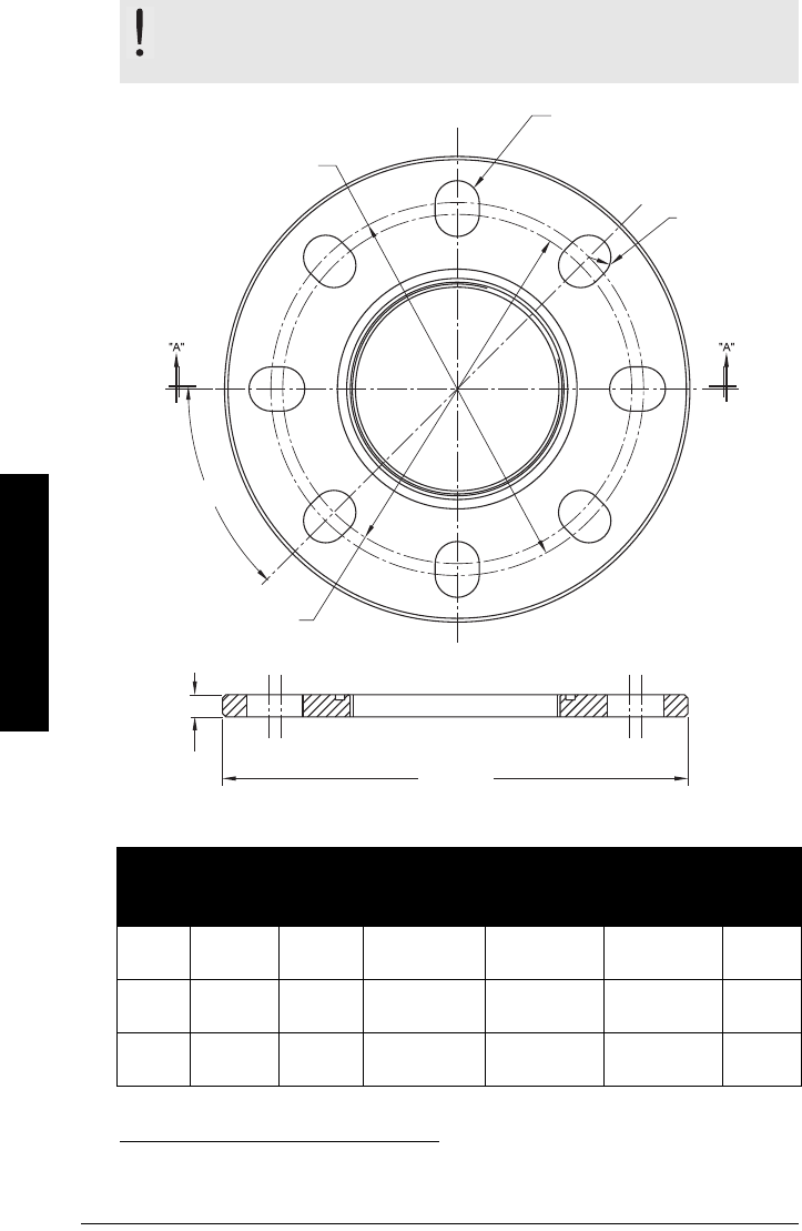
Universal Slotted Flange
Slotted Flange Dimensions and Aimer1)
WARNING: The user is responsible for the selection of bolting and
gasket materials which will fall within the limits of the flange and its
intended use and which are suitable for the service conditions.
Pipe
Size
Flange
O.D.
Thick-
ness (s)
Bolt Hole
Circle Max Ø
Bolt Hole
Circle Min Ø
Bolt Hole
radius
No. of
Slotted
Holes
3" or
80 mm
7.87"
(200 mm)
0.38"
(9.65 mm)
6.30"
(160 mm)
5.91"
(150 mm)
0.38"
(9.65 mm)
8
4" or
100 mm
9.00"
(229 mm)
0.38"
(9.65 mm)
7.52"
(191 mm)
6.89"
(175 mm)
0.38"
(9.65 mm)
8
6" or
150 mm
11.22"
(285 mm)
0.38"
(9.65 mm)
9.53"
(242 mm)
9.45"
(240 mm)
0.45"
(11.5 mm)
8
1) Universal flange mates with EN 1092-1 (PN16)/ASME B16.5 (150 lb)/JIS 2220 (10K) bolt
hole pattern.
flange
O.D.
bolt hole circle
max. diameter
slotted bolt hole
section A-A
thickness
bolt hole
radius
bolt hole circle
min. diameter
45 °

7ML19985LT01 SITRANS LR560 (PROFIBUS PA) – OPERATING INSTRUCTIONS Page 17
mmmmm
Installation
Installation
Pressure Equipment Directive, PED, 97/23/EC
SITRANS LR560 Radar Level Measurement instrument falls below the limits of Article 3,
sections 1 & 2 of the Pressure Equipment Directive (PED, 97/23/EC) as a category I
pressure accessory. However, in accordance with PED, 97/23/EC, Article 3, section 3, this
equipment has been designed and manufactured in accordance with Sound Engineering
Practice (SEP) (see EU Commission Guideline 1/5).
WARNINGS:
• Installation shall be performed only by qualified personnel and in
accordance with local governing regulations.
• SITRANS LR560 is to be used only in the manner outlined in this manual,
otherwise protection provided by the device may be impaired.
• Never attempt to loosen, remove, or disassemble process connection
or instrument housing while vessel contents are under pressure.
• The user is responsible for the selection of bolting and gasket materials
which will fall within the limits of the flange and its intended use and
which are suitable for the service conditions.
• Improper installation may result in loss of process pressure.
Notes:
• For European Union and member countries, installation must be according to ETSI
EN 302372.
• Refer to the device label for approval information.
• SITRANS LR560 units are pressure tested, meeting or exceeding the requirements of
the ASME Boiler and Pressure Vessel Code and the European Pressure Equipment
Directive.
• The serial numbers stamped in each process connection body provide a unique
identification number indicating date of manufacture.
Example: MMDDYY – XXX (where MM = month, DD = day, YY = year, and
XXX= sequential unit produced)
Further markings (space permitting) indicate flange configuration, size, pressure
class, material, and material heat code.
Note: Pertains to pressure-rated version only.
Page 18 SITRANS LR560 (PROFIBUS PA) – OPERATING INSTRUCTIONS 7ML19985LT01
mmmmm
Installation
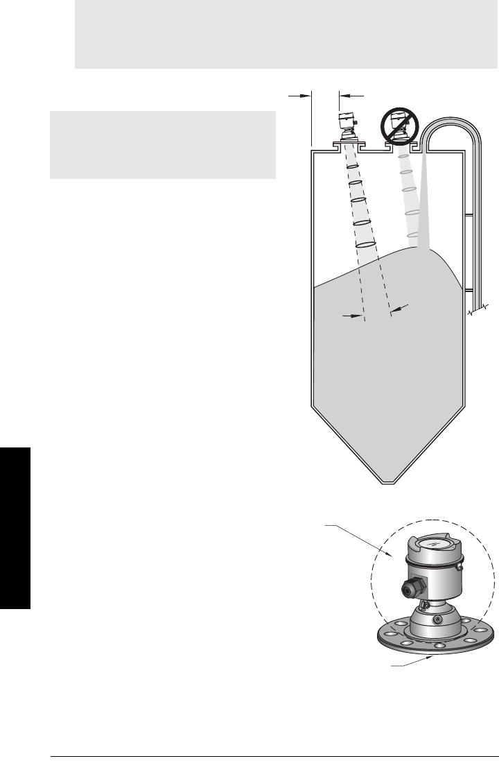
Mounting location
Nozzle location
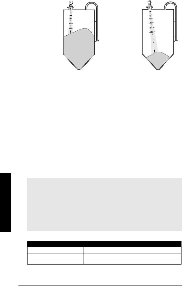
Beam angle
• Beam angle is the width of the cone
where the energy density is half of
the peak energy density.
• The peak energy density is directly
in front of and in line with the
antenna.
• There is a signal transmitted out-
side the beam angle, therefore false
targets may be detected.
Emission cone
• Keep emission cone free of
interference from ladders, pipes, I-
beams or filling streams.
• Avoid central locations on tall,
narrow vessels.
• LR560 uses circular polarization.
Rotation of device is not required to
optimize signal.
Environment
• Provide easy access for
viewing the display and
programming via the
handheld programmer.
• Provide an environment
suitable for the ambient
temperature rating.
Notes:
• Correct location is key to a successful application.
• Avoid reflective interference from vessel walls and obstructions by following the
guidelines below.
Notes:
• For details on avoiding false echoes, see
Auto False Echo Suppression (2.4.8.1.)
on
page 118.
emission
cone
min. 1 m (39")
4°
ambient temperature
–40 °C to 80 °C
(–40 °F to 176 °F)
process temperature:
–40 to +100 °C (–40 to +212 °F) or
–40 to +200 °C (–40 to +392 °F) depending on the version
7ML19985LT01 SITRANS LR560 (PROFIBUS PA) – OPERATING INSTRUCTIONS Page 19
mmmmm
Installation
Sunshield
The LR560 display can be protected by an optional sunshield if the instrument will be
mounted in direct sunlight.
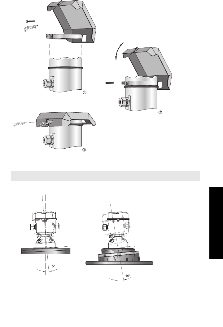
Aimer Adjustment
3" flange 4 and 6" flange
Note: Aiming will assist in measuring material in the cone.
Page 20 SITRANS LR560 (PROFIBUS PA) – OPERATING INSTRUCTIONS 7ML19985LT01
mmmmm
Installation
1) For 4" and 6" Aimer: Loosen the set screws in the locking ring.
Holding the electronics enclosure firmly, loosen the Aimer locking ring using the C
spanner supplied, until the LR560 drops down slightly. The enclosure can then be
turned freely.
Markings on the flange indicate minimum and maximum rotation (see
Removable
Display
on page 22).
2) Direct SITRANS LR560 so the antenna is pointed at an angle perpendicular to the
material surface, if possible.
3) When the desired position is reached, re-tighten the locking ring using the C
spanner, and tighten set screws.
4) For the 3" Aimer flange, tapered split washers with pressure rated versions are
provided to keep nuts and bolts perpendicular to the flange surface.
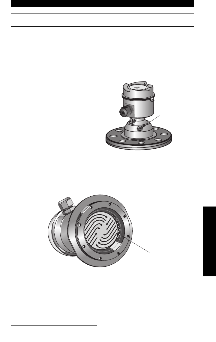
Air Purging System
For convenient cleaning, a purging inlet is provided above the antenna. The system pro-
vides an 1/8" inlet (female thread) above the antenna where clean, dry air passes to the
face of the antenna lens to clean it. The customer will supply the purging air by a manual
or automatic valve system.
NOTE: Table continues on next page.
Notes:
• Purge duration, pressure, and interval, will vary with each application. It is the user’s
responsibility to determine the requirements depending on the application and
cleaning required.
• Short duration bursts of high pressure provide more effective cleaning than continu-
ous low pressure air.
• It is the customer’s responsibility to ensure that any vacuum or pressure in the mea-
sured vessel is maintained, considering the hole that passes through the process
connection and SITRANS LR560 antenna system.
Air Consumption (Flow rate versus applied pressure)
Air Pressure (psi) Approx. inlet volume flow rate SCFMa)
20 5
40 10
Aiming is not required
for signal optimization
with 78 GHz
frequency.
Aiming will assist in
measuring material
in the cone.
Aimer
7ML19985LT01 SITRANS LR560 (PROFIBUS PA) – OPERATING INSTRUCTIONS Page 21
mmmmm
Installation
Purge Connection
• The purge connection is closed by
the manufacturer, using a 1/8" plug.
• When the plug is removed to
connect a purging system, the
operator is responsible for ensuring
that the purging circuit conforms to
"Ex" requirements: for example, by
fitting an NRV valve1).
Purge airflow
• The purge airflow is designed to create a strong vortex of air that rapidly cleans the
face of the lens.
• The air purge system can clean both dust and moisture off the lens.
• It can be used for periodic cleaning.
50 15
80 20
100 25
110 30
Recommended 90 to 110 psi for effective cleaning.
a) SCFM (standard cubic feet/minute) referenced to 14.7 psia, +68 °F and 36% relative
humidity (RH)
1) Air pressure in vessel can affect purge operation.
Air Consumption (Flow rate versus applied pressure) (cont’d)
purge process
connection with
factory-installed
1/8" NPT plug
angled holes
direct air flow

Page 22 SITRANS LR560 (PROFIBUS PA) – OPERATING INSTRUCTIONS 7ML19985LT01
mmmmm
Installation
Removable Display
• The optional display can be rotated as required, to one of 4 positions, 90 degrees
apart (see
Connecting SITRANS LR560
on page 23 for instructions).
• It can also be used to transfer parameters from one device to another. (See
Copy
Parameters to Display
on page 64.)
7ML19985LT01 SITRANS LR560 (PROFIBUS PA) – OPERATING INSTRUCTIONS Page 23
mmmmm
Wiring
Wiring
Power
Connecting SITRANS LR560
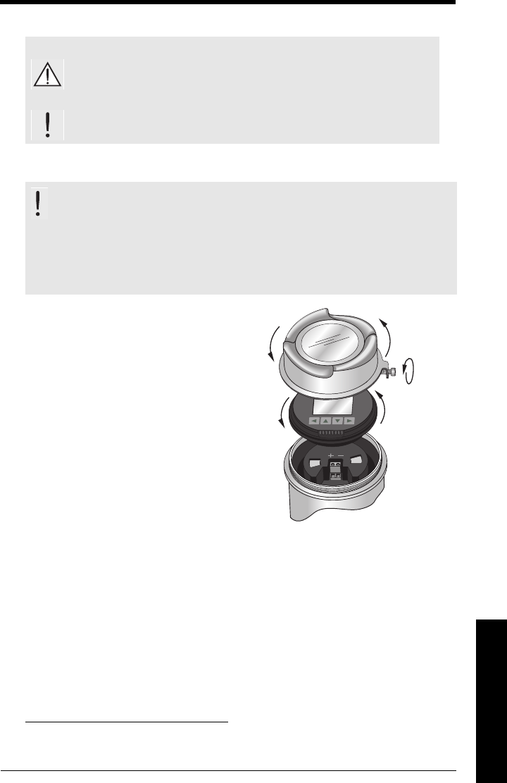
1) Loosen locking screw.
2) Remove LR560 lid.
3) Remove optional display by gently turning
the display a quarter turn counter-
clockwise until it is free.
4) Strip the cable jacket for approximately
70 mm (2.75") from the end of the
PROFIBUS PA cable, and thread the
wires through the gland1).
WARNINGS:
The DC input terminals shall be supplied from a source providing
electrical isolation between the input and output, in order to
meet the applicable safety requirements of IEC 61010-1.
All field wiring must have insulation suitable for rated voltages.
WARNINGS:
• Check the device label on your instrument, to verify the approval
rating.
• Use appropriate conduit seals to maintain IP or NEMA rating.
• See
Wiring setups for hazardous area installations
on page 25.
1) If cable is routed through conduit, use only approved suitable-size hubs for
waterproof applications.
1)
2)
3) ¼ turn
Page 24 SITRANS LR560 (PROFIBUS PA) – OPERATING INSTRUCTIONS 7ML19985LT01
mmmmm
Wirng
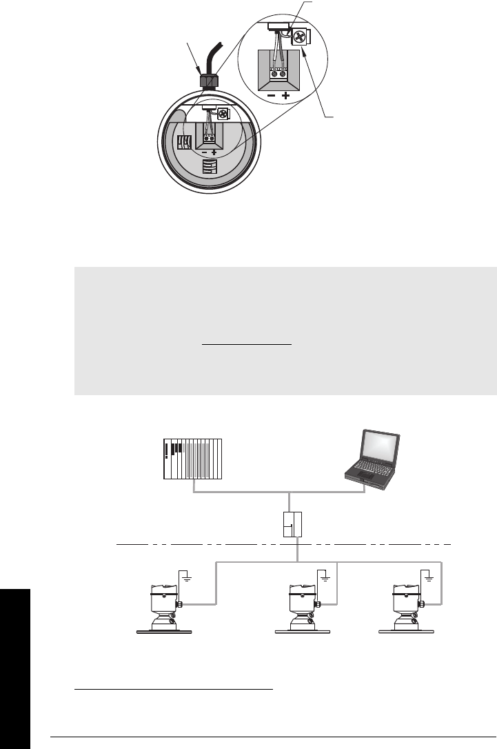
5) Connect the wires to the terminals as shown (SITRANS LR560 PA is not polarity-
sensitive.)1) 2)
6) Ground the instrument according to local regulations.
7) Tighten the gland to form a good seal.
8) Replace optional display and device lid.
9) Secure the locking screw before programming and device configuration.
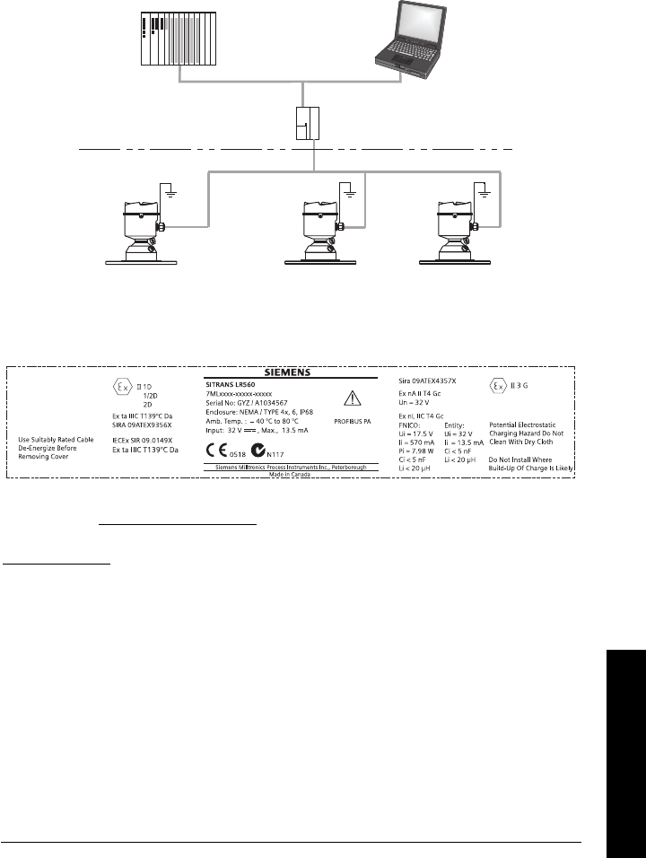
Basic PLC configuration with PROFIBUS PA
1) May be shipped with the device.
2) The instrument shield connection is internally connected to the external ground lug.
Notes:
• PROFIBUS PA must be terminated at both extreme ends of the cable for it to work
properly.
• Please refer to the
PROFIBUS PA User and Installation Guidelines
(order number
2.092), available from www.profibus.com, for information on installing PROFIBUS
devices.
• If a Weidmüller or other current limiting junction box is connected to this device,
please ensure that the current limit is set to 40 mA or higher.
cable gland 1)
(or NPT cable
entry)
cable
shield
instrument
shield
connection2)
PROFIBUS PA
PROFIBUS DP
DP/PA
coupler
active PLC
PC/laptop
PDM
SITRANS
LR560 PA
SITRANS
LR560 PA
SITRANS
LR560 PA
7ML19985LT01 SITRANS LR560 (PROFIBUS PA) – OPERATING INSTRUCTIONS Page 25
mmmmm
Wiring
Wiring setups for hazardous area installations
The following wiring options are available for hazardous area installations:
•
Non-Sparking/Energy Limited wiring (Europe) and Dust Ignition Proof wiring
(Europe/International)
on page 25
•
Non-incendive and Dust Ignition Proof wiring (US/Canada)
on page 26
In all cases, check the device label on your instrument, and confirm the approval rating.
PLC configuration with PROFIBUS PA for hazardous areas
1. Non-Sparking/Energy Limited wiring (Europe) and Dust Ignition
Proof wiring (Europe/International)
• For power demands see
Temperature De-Rating
on page 123.
• For wiring requirements follow local regulations.
•See also
Instructions Specific to Hazardous Area Installations
on page 26 and the
ATEX certificate listed above.
Hazardous Area
Non-hazardous Area
PLC
(active)
DP/PA coupler
PDM
SITRANS
LR560 PA SITRANS
LR560 PA SITRANS
LR560 PA
The ATEX certificate listed on the nameplate can be downloaded from the product page of
our website at: www.siemens.com/LR560. Go to Support > Approvals/Certificates.
The IECEx certificate listed on the nameplate can be viewed on the IECEx website. Go to:
http://iecex.iec.ch and click on Ex Equipment Certificates of Conformity then enter the
certificate number IECEx SIR 09.0149X.
Device label (ATEX/IECEx/C-TICK)

Page 26 SITRANS LR560 (PROFIBUS PA) – OPERATING INSTRUCTIONS 7ML19985LT01
mmmmm
Wirng
2. Non-incendive and Dust Ignition Proof wiring (US/Canada)
• For power demands see
Temperature De-Rating
on page 123.
Instructions Specific to Hazardous Area
Installations
(Reference European ATEX Directive 94/9/EC,
Annex II, 1.0.6)
The following instructions apply to equipment covered by certificate numbers Sira
09ATEX9356X and Sira 09ATEX4357X:
1) For use and assembly and details of marking/coding, refer to the main instructions.
2) The equipment is certified for use as Category 1D, 1/2D and 2D equipment per
certificate Sira 09ATEX9356X and may be used in hazardous zones 20, 21 and 22. The
equipment is also certified for use as Category 3G equipment per certificate Sira
09ATEX4357X and may be used in hazardous zone 2.
3) This equipment has a maximum surface temperature of 139 °C (in an 80 °C ambient).
Refer to the applicable code of practice for selection of this equipment with respect
to specific dust ignition temperatures.
4) The equipment is certified for use in an ambient temperature range of –40 °C to
80 °C.
5) The equipment has not been assessed as a safety related device (as referred to by
Directive 94/9/EC Annex II, clause 1.5).
6) Installation and inspection of this equipment shall be carried out by suitably trained
and authorized personnel in accordance with the applicable code of practice.
FM/CSA Class 1, Div 2 connection drawing number A5E02795836 can be downloaded from
the product page of our website at: www.siemens.com/LR560 under Support.
Device label (FM/CSA)

7ML19985LT01 SITRANS LR560 (PROFIBUS PA) – OPERATING INSTRUCTIONS Page 27
mmmmm
Wiring
7) The equipment shall be installed such that the supply cable is protected from
mechanical damage. The cable shall not be subjected to tension or torque. The
equipment manufacturer is not responsible for providing the supply cable.
8) Repair of this equipment shall be carried out by suitably trained and authorized
personnel in accordance with the applicable code of practice.
Special Conditions for Safe Use
The ‘X’ suffix to the certificate number relates to the following special condition(s) for
safe use:
• Parts of the enclosure may be non-conducting and may generate an ignition-
capable level of electrostatic charge under certain extreme conditions. The user
should ensure that the equipment is not installed in a location where it may be
subjected to external conditions (such as high-pressure steam), which might cause
a build-up of electrostatic charge on non-conducting surfaces.
• The end user must ensure that an ingress protection of at least IP65 is maintained
at each entry to the enclosure by use of a blanking element or cable entry device
that meets the requirements of the protection concepts type ‘n’ or increased safety
‘e’ or flameproof ‘d’.
• The supply to the equipment shall be rated for a prospective short-circuit current of
not more than 10 kA and shall protected by a suitably-rated fuse.

Page 28 SITRANS LR560 (PROFIBUS PA) – OPERATING INSTRUCTIONS 7ML19985LT01
mmmmm
Quick Start: local
Local Operation
SITRANS LR560 carries out its level measurement tasks according to settings made via
parameters. The settings can be modified locally via the Local Display Interface (LDI)
which consists of an LCD display with push buttons. You can use either the push buttons
or an infrared handheld programmer to make changes.
A Quick Start Wizard provides an easy step-by-step procedure to help you configure your
device for a simple application. There are two ways to access the wizard:
• locally (see
Quick Start Wizard via the LDI push buttons
on page 34 or
Quick
Start Wizard via the handheld programmer
on page 34)
• from a remote location (see
Quick Start Wizard via SIMATIC PDM
on page 40,
or
Configuring a new device via FDT
on page 61)
See
Level application example
on page 38 for an illustration, and for the complete range
of parameters, see
Parameter Reference
on page 62.
Activating SITRANS LR560
Power up the device. SITRANS LR560 automatically starts up in Measurement mode. A
transition screen showing first the Siemens logo and then the current firmware revision
is displayed while the first measurement is being processed. The first time the device is
configured, you will be prompted to select a language (English, German, French, Spanish
or Chinese). To change the language again, see Language (7.) on page 101.
Notes:
• To enter Program mode using the push buttons, press . Press to return to
Measurement mode.
• To toggle between Measurement and Program Mode using the handheld
programmer, press Mode .
push buttons
7ML19985LT01 SITRANS LR560 (PROFIBUS PA) – OPERATING INSTRUCTIONS Page 29
mmmmm
Quick Start: local
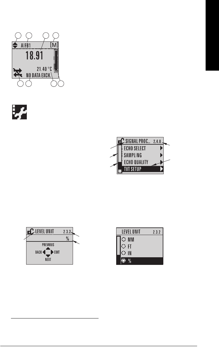
The LCD Display1)2)
Measurement mode
Normal operation
Fault present
PROGRAM mode display
Navigation view
• A visible menu bar indicates the
menu list is too long to display all
items.
• The depth of the item band on the
menu bar indicates the length of the
menu list: a deeper band indicates
fewer items.
• The position of the item band indicates the approximate position of the current item in the
list. A band halfway down the menu bar indicates the current item is halfway down the
list.
1) Press UP or DOWN arrow to switch.
2) In response to a key press request. For details, see
Key functions in Measurement
mode
on page 30.
1 – toggle indicator1) for AIFB 1 or AIFB 2
2 – identifies which AIFB is source of displayed value
3 – measured value (level, space, or distance)
4 – units
5 – bar graph indicates level
6 – secondary region indicates on request2) electronics
temperature, echo confidence, or distance
7 – text area displays status messages
8 – device status indicator
678
1342
5
S: 0 LOE
7 – text area displays a fault code and an error message
8 – service required icon appears
current
item
number
current
item
current
menu
item
band
menu
bar
parameter
value/
selection
parameter
number
parameter
name
Edit viewParameter view
Page 30 SITRANS LR560 (PROFIBUS PA) – OPERATING INSTRUCTIONS 7ML19985LT01
mmmmm
Quick Start: local
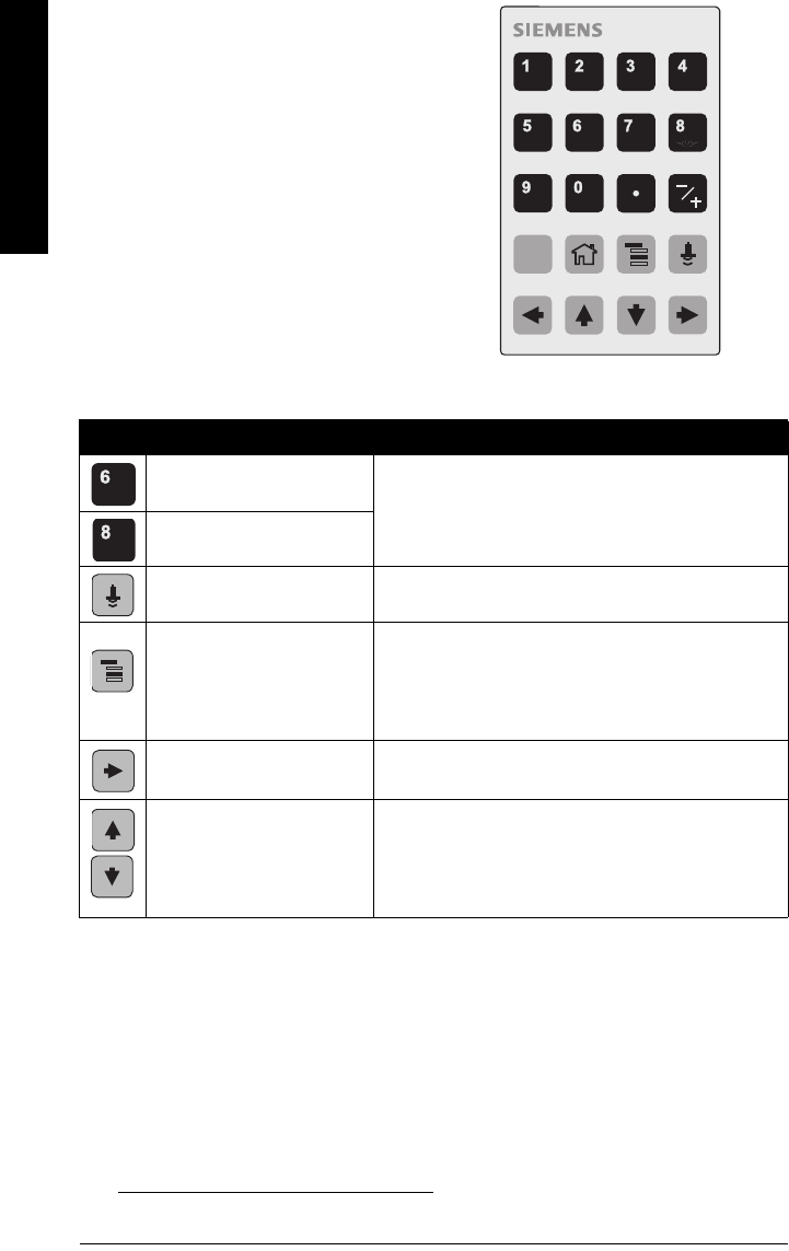
Handheld Programmer
(Part No. 7ML1930-1BK)
The programmer is ordered separately.1)
Key functions in Measurement mode
1) See Confidence (2.4.7.1.) on page 74.
Key Function Result
Displays internal enclosure
temperature reading. New value is displayed in LCD secondary region.
Displays echo confidence
value1).
Displays distance measure-
ment. New value is displayed in LCD secondary region
Mode opens PROGRAM
mode.
Opens the menu level last displayed in this power
cycle, unless power has been cycled since exiting
PROGRAM mode or more than 10 minutes have
elapsed since PROGRAM mode was used.
Then top level menu will be displayed.
RIGHT arrow
opens PROGRAM mode. Opens the top level menu.
UP or DOWN arrow
toggles between AIFB 1 and
AIFB 2.
Identifies which AIFB is the source of the displayed
value.
C
7ML19985LT01 SITRANS LR560 (PROFIBUS PA) – OPERATING INSTRUCTIONS Page 31
mmmmm
Quick Start: local
Programming SITRANS LR560
Change parameter settings and set operating conditions to suit your specific application.
(For remote operation see
Operating via SIMATIC PDM
on page 39 or
Operating via FDT
(Field Device Tool)
on page 61.)
Parameter menus
Parameters are identified by name and organized into function groups, then arranged in a
5-level menu structure (see
LCD menu structure
on page 151).
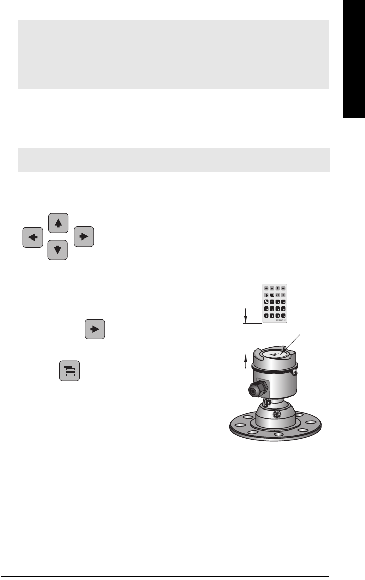
1. Enter PROGRAM mode
• Point the programmer at the display from a
maximum distance of 300 mm (1 ft).
•RIGHT arrow activates PROGRAM mode
and opens menu level 1.
•Mode opens the menu level last displayed
in PROGRAM mode within the last 10 minutes, or
menu level 1 if power has been cycled since then.
Notes:
• While the device is in PROGRAM mode the output remains active and continues to
respond to changes in the device.
• SITRANS LR560 automatically returns to Measurement mode after a period of
inactivity in PROGRAM mode (between 15 seconds and 10 minutes, depending on
the menu level).
Note: For the complete list of parameters with instructions, see
Parameter Reference
on page 62
1. QUICK START
2. SETUP
2.1. IDENTIFICATION
......................
2.3. SENSOR
2.3.1. UNIT
......................
2.3.6. RATE
2.3.6.1.RESPONSE RATE
display
handheld
programmer
max. 300 mm
(1 ft)
Page 32 SITRANS LR560 (PROFIBUS PA) – OPERATING INSTRUCTIONS 7ML19985LT01
mmmmm
Quick Start: local
2. Navigating: key functions in Navigation mode
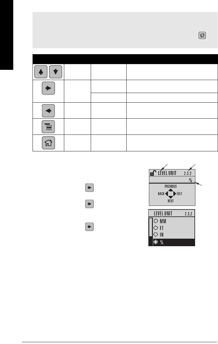
3. Editing in PROGRAM mode
Selecting a listed option
a) Navigate to the desired parameter.
b) Press RIGHT arrow to open parameter
view.
c) Press RIGHT arrow again to open Edit
mode. The current selection is highlighted.
Scroll to a new selection.
d) Press RIGHT arrow to accept it
The LCD returns to parameter view and displays
the new selection.
Notes:
• In Navigation mode ARROW keys move to the next menu item in the direction of the
arrow.
• For Quick Access to parameters via the handheld programmer, press Home ,
then enter the menu number, for example: 3.1. Echo Profile
Key Name Menu level Function
UP or DOWN
arrow
menu or
parameter Scroll to previous or next menu or parameter.
RIGHT
arrow
menu Go to first parameter in the selected menu, or
open next menu.
parameter Open Edit mode.
LEFT
arrow menu or
parameter Open parent menu.
Mode menu or
parameter Change to MEASUREMENT mode.
Home menu or
parameter Open top level menu: menu 1.
parameter name parameter
number
current
selection
7ML19985LT01 SITRANS LR560 (PROFIBUS PA) – OPERATING INSTRUCTIONS Page 33
mmmmm
Quick Start: local
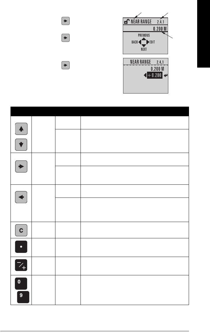
Changing a numeric value
a) Navigate to the desired parameter.
b) Press RIGHT arrow to open parameter
view. The current value is displayed.
c) Press RIGHT arrow again to open Edit
mode. The current value is highlighted.
d) Key in a new value.
e) Press RIGHT arrow to accept it. The LCD
returns to parameter view and displays the new
selection.
Key functions in Edit mode
Key Name Function
UP or
DOWN
arrow
Selecting
options Scrolls to item.
Alpha-
Numeric
editing
- Increments or decrements digits
- Toggles plus and minus sign
RIGHT
arrow
Selecting
options
- Accepts the data (writes the parameter)
- Changes from Edit to Navigation mode
Numeric
editing
- Moves cursor one space to the right
- or with cursor on Enter sign, accepts the data and
changes from Edit to Navigation mode
LEFT
arrow
Selecting
options Cancels Edit mode without changing the parameter
Numeric
editing
- Moves cursor to plus/minus sign if this is the first key
pressed
- or moves cursor one space to the left.
- or with cursor on Enter sign, cancels the entry
Clear Numeric
editing Erases the display.
Decimal
point
Numeric
editing Enters a decimal point.
Plus or
minus sign
Numeric
editing Changes the sign of the entered value.
to
Numeral Numeric
editing Enters the corresponding character.
current
value
parameter
number
parameter name
Page 34 SITRANS LR560 (PROFIBUS PA) – OPERATING INSTRUCTIONS 7ML19985LT01
mmmmm
Quick Start: local
Quick Start Wizard via the LDI push buttons
1) Press to enter Program mode.
2) Choose Quick Start (1.), and then Quick Start Wizard (1.1.).
3) Follow the steps then choose Finish to save Quick Start parameter changes and
return to Program menu, or press to return to Measurement mode.
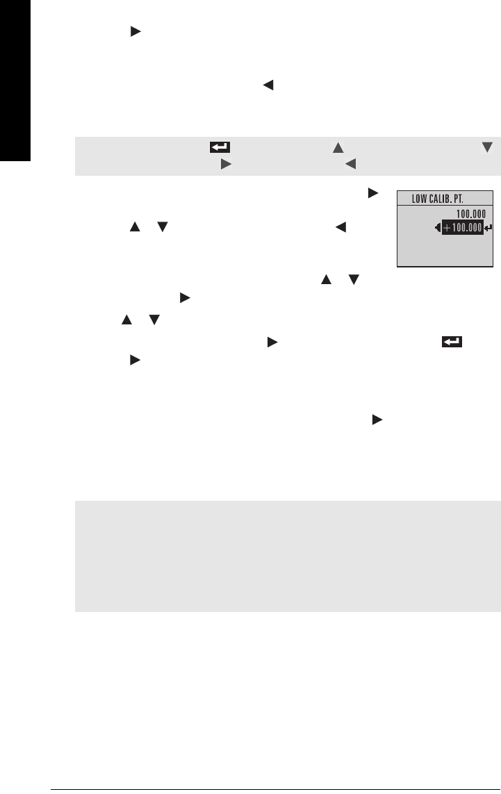
To add or delete digits using the push buttons:
1) Navigate to the parameter you wish to modify and press
to edit it. The value will be highlighted.
2) Press or to delete the highlighted value, or to
modify the value from the left-most digit, starting with the
plus/minus sign.
3) With the plus or minus sign highlighted, press or to
change it. Press to highlight the next digit to the right.
4) Use or to modify the highlighted digit. Scroll past 9 to reach the decimal point.
5) When the value is complete, press until the Enter icon is highlighted , then
press to accept the value.
To modify a text string:
1) Navigate to the parameter you wish to modify and press to edit it. The string will
be highlighted.
2) Follow the same steps as above, to add, delete, or modify characters.
Quick Start Wizard via the handheld programmer
Note: When the Enter icon is highlighted, press to insert a digit on the right,
to delete the right-most digit, to accept the value, or to cancel.
Notes:
• The Quick Start wizard settings are inter-related and changes apply only after you
choose Finish in the Wizard Complete step.
• Do not use the Quick Start wizard to modify individual parameters: see instead
Parameter Reference
on page 62. (Perform customization only after the Quick Start
has been completed.)
• Default settings in the parameter tables are indicated with an asterisk (*).
7ML19985LT01 SITRANS LR560 (PROFIBUS PA) – OPERATING INSTRUCTIONS Page 35
mmmmm
Quick Start: local
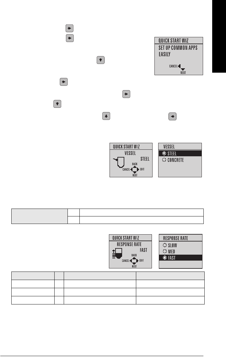
1. Quick Start
1.1. Quick Start Wizard
a) Point the programmer at the display from a maximum distance of 300 mm (1 ft) and
press RIGHT arrow to activate PROGRAM mode and open menu level 1.
b) Press RIGHT arrow twice, to navigate to menu item 1.1
and open the Quick Start Wizard.
c) At each step, press DOWN arrow to accept default
values and move directly to the next item,
or RIGHT arrow to open Edit mode: the current selection is highlighted.
d) Scroll to desired item and press RIGHT arrow to store the change, then press
DOWN arrow to continue.
e) At any time you can press UP arrow to go back, or LEFT arrow to cancel
and return to Measurement mode.
Vessel
Select vessel construction material
.
• Selecting either STEEL or CONCRETE
does a functional reset (see Master
Reset (4.2.) on page 87).
• Selecting STEEL changes the setting
for Position Detect (2.4.5.2.) to Rising
Edge and for Algorithm (2.4.5.1.) to F.
• Selecting CONCRETE changes the setting for Position Detect (2.4.5.2.) to Rising Edge
and for Algorithm (2.4.5.1.) to ALF.
Response Rate
Use a setting just faster than the maximum vessel filling or vessel emptying rate (whichever
is greater).
Options * STEEL
CONCRETE
Response Rate Vessel Fill/Empty rate/min Filter Time Constant (2.5.8.1.)
SLOW 0.1 m/min (0.32 ft/min) 10 s
MED * 1.0 m/min (3.28 ft/min) 10 s
FAST 10.0 m/min (32.8 ft/min) 0 s
Parameter View Edit mode
Sets the reaction speed of the device to
measurement changes in the target range.
Selecting SLOW changes setting for
Average amount (2.8.3.) to 0.9.
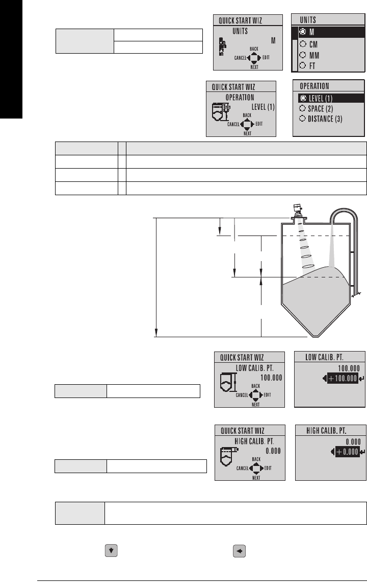
Page 36 SITRANS LR560 (PROFIBUS PA) – OPERATING INSTRUCTIONS 7ML19985LT01
mmmmm
Quick Start: local
Units
Low Calibration Point
High Calibration Point
Wizard Complete
To transfer Quick Start values to the device and return to Program menu, press
DOWN arrow (Finish). Then press LEFT arrow to return to Measurement mode.
Operation Description
LEVEL (1) * Distance from Low Calibration Point to material surface.
SPACE (2) Distance from High Calibration Point to material surface.
DISTANCE (3) Distance from Sensor Reference Point to material surface.
Options BACK, CANCEL, FINISH (Display returns to 1.1 Quick Start Wizard menu when
Quick Start is successfully completed.)
Sensor measurement units.
Options M, CM, MM, FT, IN
Default: M
Operation
High Calibration
Point
Low Calibration Point
Level
Space
Distance
sensor reference point
(flange face: see
Dimensions
on page 12)
Distance from Sensor Reference Point to
Low Calibration Point: usually process
empty level.
Values Range: 0.0000 to 100.000 m
Distance from Sensor Reference Point to
High Calibration Point: usually process full
level.
Values Range: 0.0000 to 100.000 m
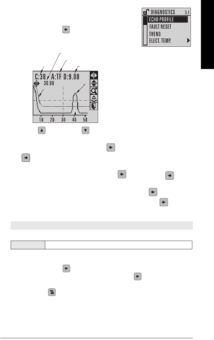
7ML19985LT01 SITRANS LR560 (PROFIBUS PA) – OPERATING INSTRUCTIONS Page 37
mmmmm
Quick Start: local
Requesting an Echo Profile
• In PROGRAM mode, navigate to: Level Meter >
Diagnostics (3.) > Echo Profile (3.1.).
• Press RIGHT arrow to request a profile.
•Use UP or DOWN arrow to scroll to an icon. When an icon is highlighted
that feature becomes active.
• To move a cross-hair, press RIGHT arrow to increase the value, LEFT arrow
to decrease.
• To Zoom into an area, position the intersection of the cross-hairs at the center of
that area, select Zoom, and press RIGHT arrow . Press LEFT arrow to Zoom
out.
• To update the profile, select Measure and press RIGHT arrow .
• To return to the previous menu, select Exit then press RIGHT arrow .
Device Address
The unique address of the device on the network (also called PROFIBUS address).
a) In PROGRAM mode, navigate to: Level Meter > Communication (5.) > Device
Address (5.1.).
b) Press RIGHT arrow twice to open parameter view and enable Edit mode.
c) If required, key in a new value and press RIGHT arrow to accept it. The LCD
displays the new value.
d) Press Mode to return to Measurement mode.
Note: See
Master Reset
on page 55 to reset Device Address to 126.
Values 0 - 126. Default: 126
algorithm: tF (trueFirst)
confidence distance from flange face to target
TVT
echo
measure
exit
distance from Low Calibration Point to vertical cross-hair
zoom
pan left/right - selected
pan up/down
Echo amplitude (in dB)
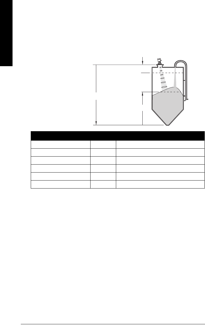
Page 38 SITRANS LR560 (PROFIBUS PA) – OPERATING INSTRUCTIONS 7ML19985LT01
mmmmm
Quick Start: local
Level application example
The application is a vessel that takes an average 3 hours (180 minutes) to fill and 3 weeks
to empty.
Fill rate = 0.08 m/minute [(Low Cal Pt. minus High Cal Pt.) / fastest of fill or empty time]
= (15.5 m – 1 m) / 180 min.
= 14.5 m /180 min. = 0.08 m/min.
Therefore SLOW response rate (0.1 m/minute) can be selected.
Quick Start Parameter Setting Description
Vessel STEEL Selects vessel construction material.
Response Rate SLOW Resets Fill Rate/ Empty Rate to 0.1 m/minute.
Units M Sensor measurement units.
Operation LEVEL (1) Material level referenced from Low Cal. Point.
Low Calibration Point 15.5 Process empty level.
High Calibration Point 1.0 Process full level.
sensor reference point
Level
Low Cal. Point
High Cal.
Point
15.5 m
1.0 m
SITRANS
LR560
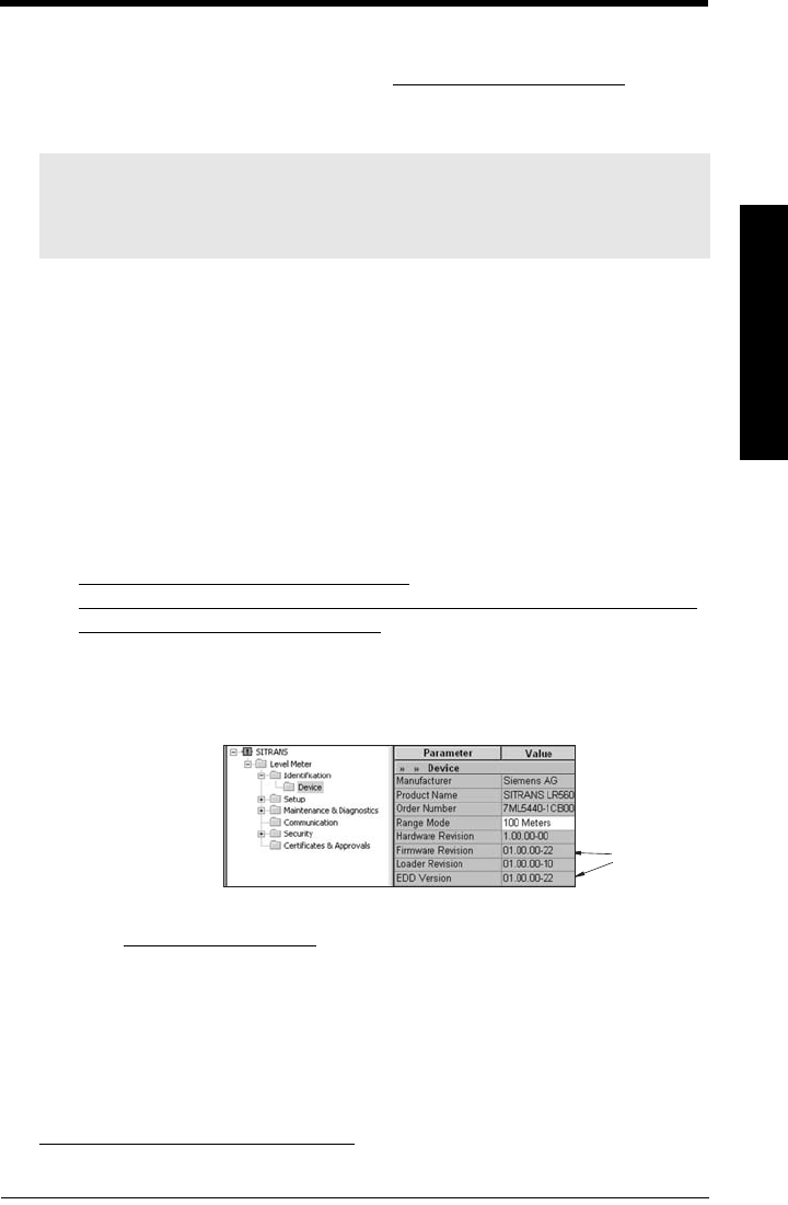
7ML19985LT01 SITRANS LR560 (PROFIBUS PA) – OPERATING INSTRUCTIONS Page 39
mmmmm
SIMATIC PDM
Operating via SIMATIC PDM
SIMATIC PDM is a software tool used to commission and maintain SITRANS LR560 and other
process devices. Please consult the operating instructions or online help for details on using
SIMATIC PDM. (You can find more information at www.siemens.com/simatic-pdm.)
Functions in SIMATIC PDM
SIMATIC PDM monitors the process values, alarms and status signals of the device. It allows
you to display, compare, adjust, verify, and simulate process device data; also to set schedules
for calibration and maintenance.
Parameters are identified by name and organized into function groups. See
LCD menu
structure
on page 151 for a chart1) and
Changing parameter settings using SIMATIC
PDM
on page 44 for more details.
See
Parameters accessed via pull-down menus
on page 44 for parameters that do not
appear in the menu structure in SIMATIC PDM.
SIMATIC PDM Version
Check the support page of our website to make sure you have the latest version of SIMATIC
PDM, the most recent Service Pack (SP) and the most recent hot fix (HF). Go to:
https://support.automation.siemens.com/WW/
llisapi.dll?func=cslib.csinfo&lang=en&siteid=csius&aktprim=0&extranet=standard&vie
wreg=WW&objid=10806857&treeLang=en
Electronic Device Description (EDD)
You can locate the EDD in Device Catalog, under Sensors/Level/Echo/Siemens AG/
SITRANS LR560. The EDD revision must match the Firmware revision in the device.
To install a new EDD
1) Go to www.siemens.com/LR560 > Support > Software Downloads to download the
most up-to-date EDD from the product page of our website.
2) Save the files to your computer and extract the zipped file to an easily accessed
location.
3) Launch SIMATIC PDM – Manage Device Catalog, browse to the unzipped EDD file
and select it.
Notes:
• For a complete list of parameters see
Parameter Reference
on page 62.
• While the device is in PROGRAM mode the output remains active and continues to
respond to changes in the device.
1) The menu structure for SIMATIC PDM is almost identical to that for the LCD.
matching
Firmware
and EDD
revisions
To check it in PDM,
go to Level Meter >
Identification >
Device.

Page 40 SITRANS LR560 (PROFIBUS PA) – OPERATING INSTRUCTIONS 7ML19985LT01
mmmmm
SIMATIC PDM
Configuring a new device
1) Check that you have the most recent EDD, and if necessary update it (see
To install a
new EDD
above).
2) Set Address via handheld programmer (default for PROFIBUS PA is 126). (See Device
Address (5.1.) on page 100, to use SIMATIC PDM.)
• In PROGRAM mode, navigate to: Level Meter > Communication (5.) > Device
Address (5.1.).
• Press RIGHT arrow twice, to open parameter view and enable Edit mode.
• If required, key in a new value and press RIGHT arrow to accept it. The LCD
displays the new value.
• Press Mode to return to Measurement mode.
3) Launch SIMATIC Manager and create a new project for LR560.
4) Open the menu Device – Master Reset and click on Factory Defaults.
5) After the reset is complete click on Close, then upload parameters to the PC/PG.
6) Configure the device via the Quick Start wizard.
Set Address
Open the menu Device – Set Address, enter a value for New Address, and click on Assign
Address.
Quick Start Wizard via SIMATIC PDM
The graphic Quick Start Wizard provides an easy step-by-step procedure that configures the
device for a simple application.
Please consult the operating instructions or online help for details on using SIMATIC PDM.
1) If you have not already done so, check that you have the most up-to-date Electronic
Device Description (EDD) for your instrument. (See
Electronic Device Description
(EDD)
on page 39.)
2) Launch SIMATIC Manager and create a new project for LR560. Application Guides
for setting up PROFIBUS PA devices with SIMATIC PDM can be downloaded from
the product page of our website at: www.siemens.com/LR560.
Notes:
• Clicking on Cancel during an upload from device to SIMATIC PDM will result in some
parameters being updated.
• Application Guides for setting up PROFIBUS PA devices with SIMATIC PDM can be
downloaded from the product page of our website at: www.siemens.com/LR560.
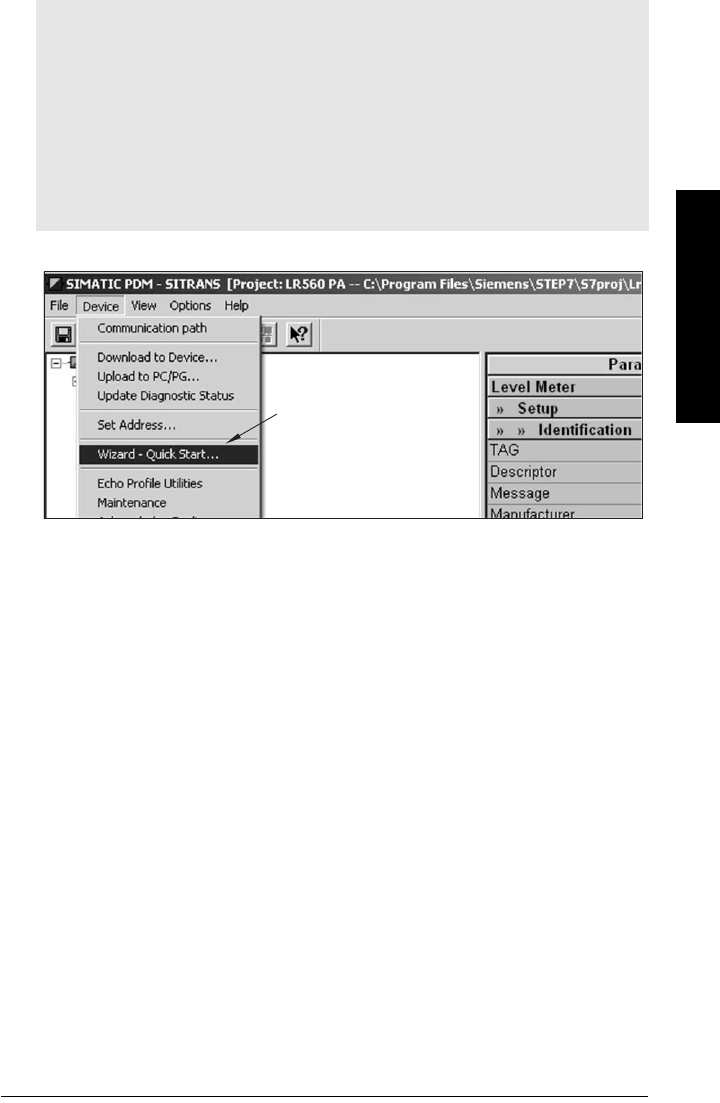
7ML19985LT01 SITRANS LR560 (PROFIBUS PA) – OPERATING INSTRUCTIONS Page 41
mmmmm
SIMATIC PDM
Quick Start
Launch SIMATIC PDM, open the menu Device – Wizard - Quick Start, and follow steps 1 to 4.
Notes:
• The Quick Start wizard settings are inter-related and changes apply only after you
click on FINISH AND DOWNLOAD at the end of the last step to save settings offline
and transfer them to the device.
• Do not use the Quick Start Wizard to modify individual parameters: For quick access
to echo profile parameters see
Echo Setup
on page 50, or see
Parameter Reference
on page 62 for a complete list. (Perform customization only after the Quick Start has
been completed.)
• Click on BACK to return and revise setting or CANCEL to exit the Quick Start.
• For a vessel with obstructions see
Auto False Echo Suppression
on page 48.
Quick
Start
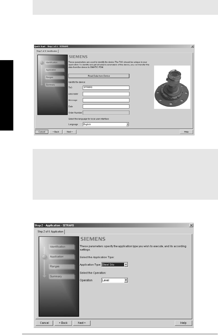
Page 42 SITRANS LR560 (PROFIBUS PA) – OPERATING INSTRUCTIONS 7ML19985LT01
mmmmm
SIMATIC PDM
Step 1 – Identification
1) Click on Read Data from Device to upload Quick Start parameter settings from the
device to the PC/PG and ensure PDM is synchronized with the device.
2) Click on NEXT to accept the default values. (Descriptor, Message, and Date fields
can be left blank.)
Step 2 – Application Type
1) Select the application type: steel or concrete vessel. [This changes the setting for
Position Detect (2.4.5.2.) to Rising Edge.]
2) Click on NEXT.
Note: The layout of the dialog boxes shown may vary according to the resolution set-
ting for your computer monitor.
Notes:
• Selecting either STEEL or CONCRETE does a functional reset (see Master Reset
(4.2.) on page 87).
• Selecting STEEL changes the setting for Position Detect (2.4.5.2.) to Rising Edge. and
for Algorithm (2.4.5.1.) to F.
• Selecting CONCRETE changes the setting for Position Detect (2.4.5.2.) to Rising Edge
and for Algorithm (2.4.5.1.) to ALF.
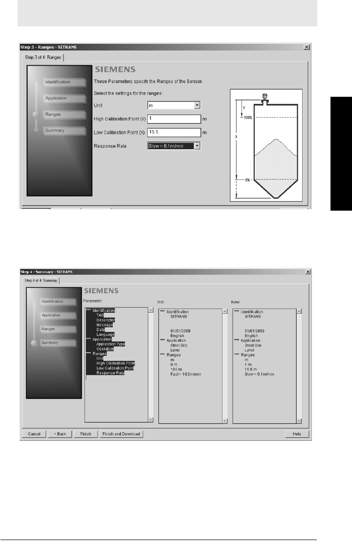
7ML19985LT01 SITRANS LR560 (PROFIBUS PA) – OPERATING INSTRUCTIONS Page 43
mmmmm
SIMATIC PDM
Step 3 – Range
Set the parameters, and click on NEXT.
Step 4 – Summary
Check parameter settings, and click on BACK to return and revise values, FINISH to save
settings offline, or FINISH AND DOWNLOAD to save settings offline and transfer them to
the device.
The message Quick Start was successful will appear. Click on OK.
Note: Selecting SLOW Response Rate changes setting for Average amount (2.8.3.) to
0.9.
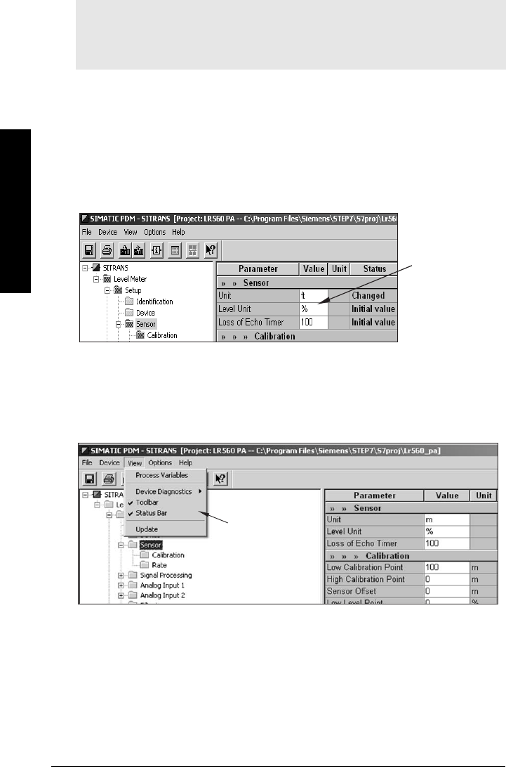
Page 44 SITRANS LR560 (PROFIBUS PA) – OPERATING INSTRUCTIONS 7ML19985LT01
mmmmm
SIMATIC PDM
Changing parameter settings using SIMATIC PDM
Many parameters are accessed via the 5-level menu in PDM. See
Parameters accessed via
pull-down menus
on page 44 for the others.
1) Launch SIMATIC PDM, connect to SITRANS LR560, and upload data from the
device.
2) Adjust parameter values in the parameter value field then press Enter. The status
fields read Changed.
3) Open the Device menu, click on Download to Device, then use File – Save, to save
parameter settings. The status fields are cleared.
Parameters accessed via pull-down menus
You have access to a number of functions via pull-down menus from the menu bar. under
Device or View.
For a complete list, see
Pull-down menus
on page 45.
Notes:
• For a complete list of parameters, see
Parameter Reference
on page 62.
• Clicking on Cancel during an upload from device to SIMATIC PDM will result in some
parameters being updated.
value
fields
pull-down
menus

7ML19985LT01 SITRANS LR560 (PROFIBUS PA) – OPERATING INSTRUCTIONS Page 45
mmmmm
SIMATIC PDM
Pull-down menus
Echo Profile Utilities
Open the menu Device – Echo Profile Utilities and click on the appropriate tab for easy access
to:
•
Echo profile
on page 46
•
Echo profile data logging
on page 46 (via
Echo profile
tab)
•
View Saved Echo Profiles
on page 46
•
TVT Shaper
on page 47
•
Auto False Echo Suppression
on page 48
•
Echo Setup
on page 50
Device menus page View menus page
Communication path Process Variables 56
Download to device
Upload to PC/PG
Update Diagnostic Status
Device Diagnostics 57
Set Address 40 Toolbar
Status bar
Wizard - Quick Start 41 Update
Echo Profile Utilities 45
Maintenance 50
Acknowledge Faults 51
Wear 51
Simulation 52
Write Locking 54
Master Reset 55
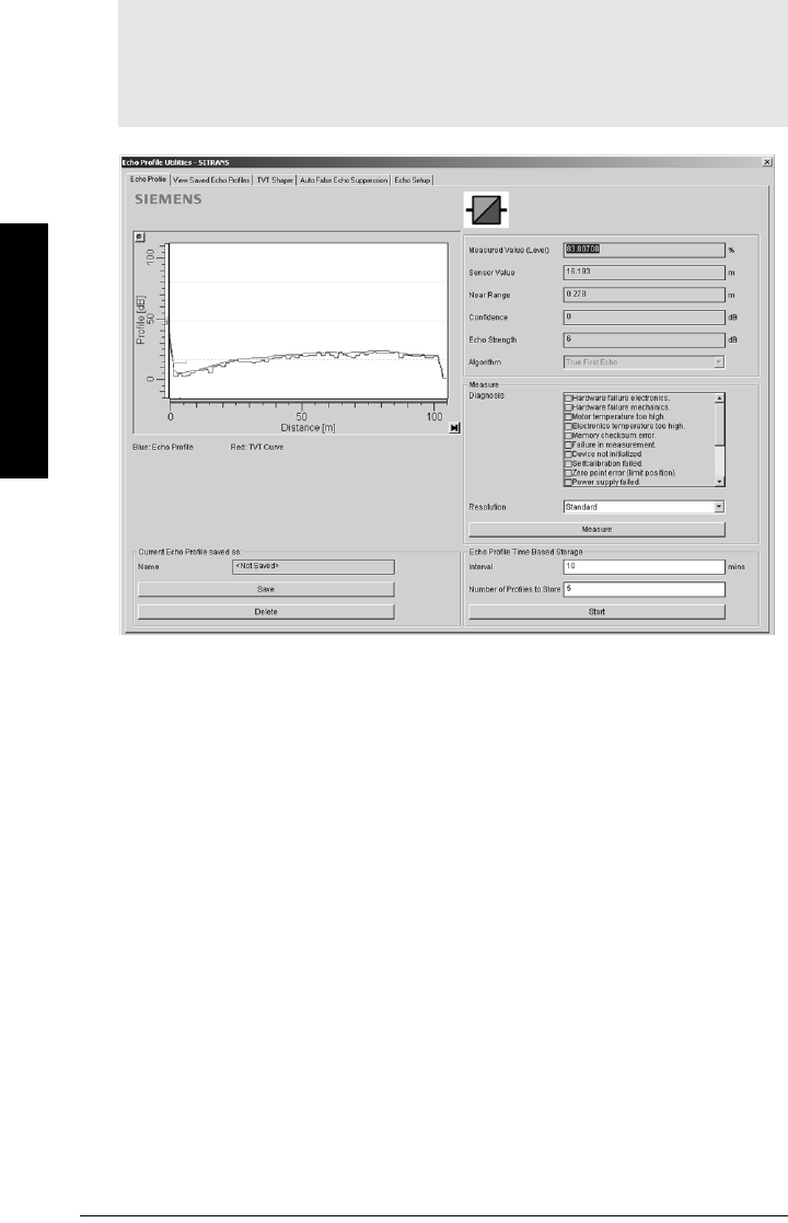
Page 46 SITRANS LR560 (PROFIBUS PA) – OPERATING INSTRUCTIONS 7ML19985LT01
mmmmm
SIMATIC PDM
Echo profile
• In the Echo Profile Utilities window click on the tab Echo Profile.
• Click on the Measure button to update the profile. Select Standard Resolution to
update the profile faster. Detailed Resolution uploads all data points.
• Click on the Save button and in the new window enter a name (maximum 50
characters) and click on OK.
• Click on Close to exit.
Echo profile data logging
You can store up to 60 profiles at a selected interval (maximum 60 minutes).
Inside Echo Profile Utilities, in the Echo Profile Time Based Storage group:
• Enter the desired interval between stored profiles.
• Enter the desired number of profiles to be stored (maximum 60).
• Click on Start. A message appears warning of the time delay and warning that all
previous saved profiles will be overwritten. Click on OK to proceed. The new profiles
will be saved with their date and time.
• Click on the tab View Saved Echo Profiles to view the stored profiles
View Saved Echo Profiles
To view a saved profile, click on the tab View Saved Echo Profiles.
Notes:
• Double click on each axis to see the Xscale and Data Scale values. Right-click or
Left-click on the axis and drag to reposition the scale.
• After saving a profile click on Close, not the x button, to close the Echo Profile
Utilities window, otherwise the profile will not be saved.
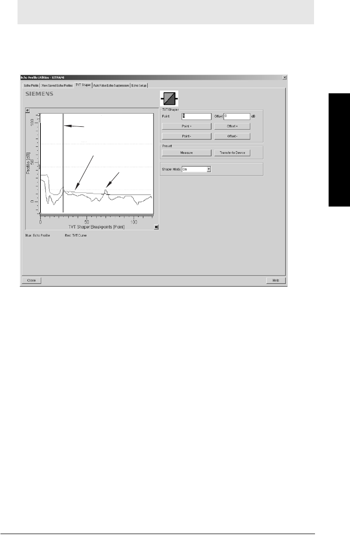
7ML19985LT01 SITRANS LR560 (PROFIBUS PA) – OPERATING INSTRUCTIONS Page 47
mmmmm
SIMATIC PDM
TVT Shaper
This feature allows you to manually adjust the TVT to avoid false echoes caused by
obstructions. (For an explanation see
Auto False Echo Suppression (2.4.8.1.)
on page 118.)
Open the menu Device – Echo Profile Utilities and click on the tab TVT Shaper.
• Turn Shaper Mode On.
• Click on Measure to refresh the echo profile and load the current TVT from the
device.
• Change the position of the cursor on the TVT using the Point+ and Point– buttons:
raise and lower the TVT using Offset+ and Offset–.
• Alternatively, enter values for Point and Offset directly into the dialog boxes.
• Click on Transfer to Device.
Note: Double click on each axis to see the Xscale and Data Scale values. Right-click or
Left-click on the axis and drag to reposition the scale.
TVT
cursor
echo profile
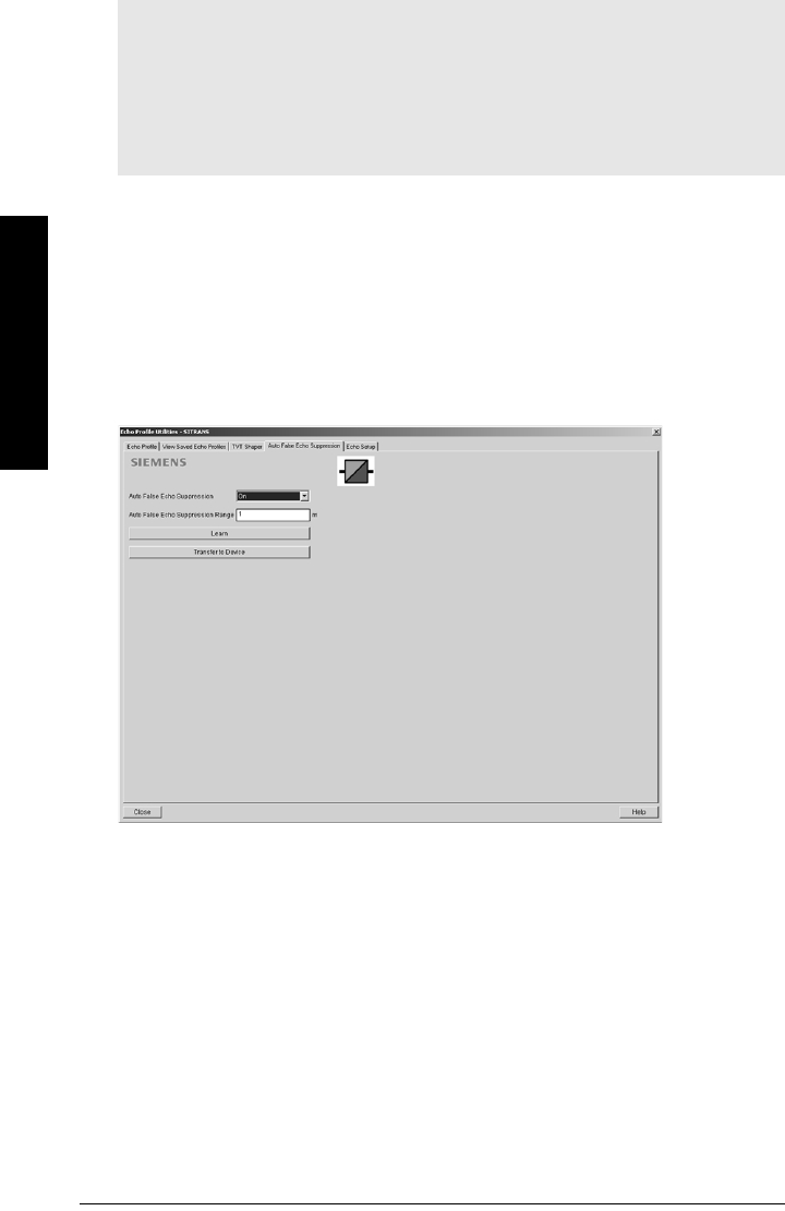
Page 48 SITRANS LR560 (PROFIBUS PA) – OPERATING INSTRUCTIONS 7ML19985LT01
mmmmm
SIMATIC PDM
Auto False Echo Suppression
If you have a vessel with known obstructions, we recommend using Auto False Echo
Suppression to prevent false echo detection. This feature can also be used if the device
displays a false high level, or the reading is fluctuating between the correct level and a
false high level.
The device learns the echo profile over the whole measurement range and the TVT is shaped
around all echoes present at that moment. (See
Auto False Echo Suppression (2.4.8.1.)
on
page 118 for a more detailed explanation.)
The learned TVT will be applied over a specified range. The default TVT is applied over the
remainder of the measurement range.
1) Make sure the material level is below all known obstructions.
2) Determine Auto False Echo Suppression Range. Measure the actual distance from
the sensor reference point to the material surface using a rope or tape measure.
Subtract 0.5 m (20") from this distance, and use the resulting value.
Notes:
• Make sure material level is below all known obstructions at the moment Auto False
Echo Suppression is used to learn a custom TVT (Time Varying Threshold). We
recommend an empty or almost empty vessel.
• Note the distance to material level when the environment is learned, and set Auto
False Echo Suppression Range to a shorter distance to avoid the material echo being
screened out.
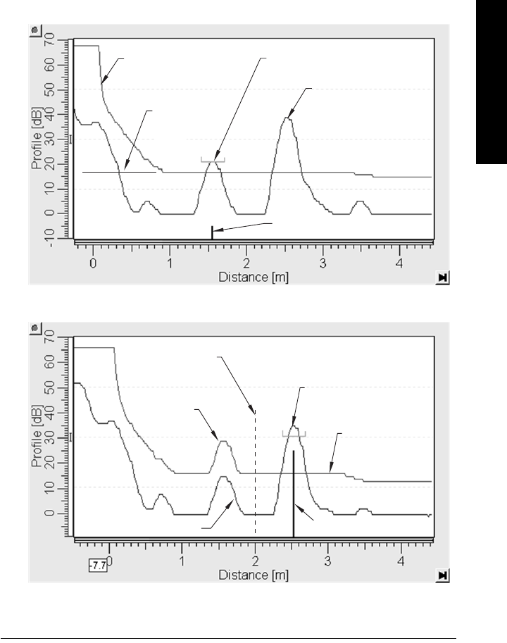
7ML19985LT01 SITRANS LR560 (PROFIBUS PA) – OPERATING INSTRUCTIONS Page 49
mmmmm
SIMATIC PDM
3) Open the menu Device – Echo Profile Utilities and click on the tab Auto False Echo
Suppression.
4) Make sure Auto False Echo Suppression is On.
5) Enter the value for Auto False Echo Suppression Range.
6) Click on Learn. The message appears: ’This will learn a new echo profile. Once done
it cannot be undone’. Click on OK.
7) Once ’Auto TVT Learn’ is complete, click on Transfer to Device. To exit, click on Close.
Auto TVT is enabled and the learned TVT will be used.
8) To turn Auto False Echo Suppression off or on, reopen the Auto False Echo
Suppression window and click on Off or On.
Before Auto False Echo Suppression
default TVT
TVT
Hover
Level
Level (db)
echo marker
After Auto False Echo Suppression
material level
false echo
Auto False Echo
Suppression Range
echo marker
Level (db)
default
TVT
material level
false echo
learned
TVT
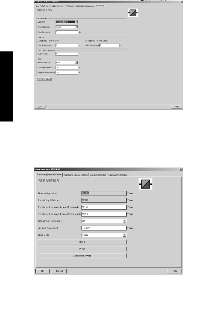
Page 50 SITRANS LR560 (PROFIBUS PA) – OPERATING INSTRUCTIONS 7ML19985LT01
mmmmm
SIMATIC PDM
Echo Setup
Provides quick access to echo selection, filtering, and response rate parameters.
Open the menu Device – Echo Profile Utilities and click on Echo Setup.
Maintenance
You can set schedules for:
• maintenance of the device based on its projected lifetime
• maintenance of the sensor based on its projected lifetime
• service
• calibration

7ML19985LT01 SITRANS LR560 (PROFIBUS PA) – OPERATING INSTRUCTIONS Page 51
mmmmm
SIMATIC PDM
To set Device/Sensor Maintenance schedules:
1) Open the menu Device – Maintenance, and click on the Remaining Device/
Sensor Lifetime tab.
2) Modify desired values, and if desired, activate reminders for either or both of
Reminder 1 (Required)/Reminder 2 (Demanded).
3) Click on Write.
4) Click on Read, to see the effects of your modification.
5) Click on Snooze to add a year to the Total Expected Device Life.
To set Service/Calibration schedules:
1) Open the menu Device – Maintenance, and click on the Service/Calibration
Schedule tab.
2) Modify desired values, and if desired, activate reminders for either or both of
Reminder 1 (Required)/Reminder 2 (Demanded).
3) Click on Write.
4) Click on Read, to see the effects of your modification.
5) Click on Service/Calibration Performed to reset the schedule.
Acknowledge Faults
Open the menu Device – Acknowledge Faults, select the appropriate item from the Extended
Diagnostics pull-down menu, and click on Transfer.
Wear
Reports the number of hours the device has been operating, and the number of times it has
been powered up.
Open the menu Device – Wear to view:
• Powered Hours
• Power-on Resets
Analog Input Function Blocks
AIFB1 and AIFB2 Output Conversion
Two identical, independent Analog Input Function Blocks allow you to modify the output to the
LCD and the control system by:
• input scaling
• output scaling
• setting alarms and warnings
• selecting display units, damping
• defining the response to a Fail-safe condition
Go to Level Meter > Setup > Analog Input 1 (or Analog Input 2) for access to these
parameters. (See
AIFB (simulation, mode and status)
on page 127 for detailed
explanations.)
You can also simulate input and output values, accessed via pull-down menus: see
Simulation
on page 52.
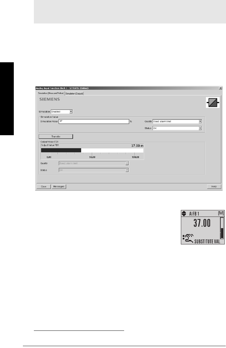
Page 52 SITRANS LR560 (PROFIBUS PA) – OPERATING INSTRUCTIONS 7ML19985LT01
mmmmm
SIMATIC PDM
Simulation
For more details see
AIFB (simulation, mode and status)
on page 127.
Simulate Analog Input to AIFB1 or AIFB2
You can test your device configuration by simulating the sensor value and status being
fed into the Analog Input Function Block, to ensure that your sensor calibration has been
correctly carried out for your application.
1) Open the menu Device – Simulation, and select the desired function block.
2) Click on the tab Simulation (Measured value).
3) Enable simulation, enter a value in sensor units, set the desired quality and status1),
and click on Transfer.
4) The substitute Output value is displayed in PDM and on the
LCD display, in units defined for the function block in
question. See
Simulate Output
below, to set the output
mode.
5) After simulation is complete, disable simulation and click on
Transfer.
Notes:
• The Simulation parameter influences output to the control system.
• Make sure that simulation is disabled after simulation is complete.
1) See
Status Byte
on page 132 for more information on status and quality.

7ML19985LT01 SITRANS LR560 (PROFIBUS PA) – OPERATING INSTRUCTIONS Page 53
mmmmm
SIMATIC PDM
Simulate Output
Manual (user-defined value)
1) Open the menu Device – Simulation, select function block 1 or 2, and click on the tab
Simulation (Output).
2) Select Manual Mode (from options AUTO, Manual, or Out of Service) and click on
Transfer.
3) Enter simulated value and click on Transfer.
4) After simulation is complete, return to Simulate Output, reselect AUTO mode, and
click on Transfer.
Out-of-Service
In Out of Service mode, an out of service status is associated with the value, telling the
master that the value is invalid. This feature can be used during maintenance.
1) Open the menu Device – Simulation, select function block 1 or 2, and click on the tab
Simulation (Output).
2) Select Out of Service Mode and click on Transfer.
3) After maintenance is complete, return to Simulate Output, reselect AUTO mode, and
click on Transfer.
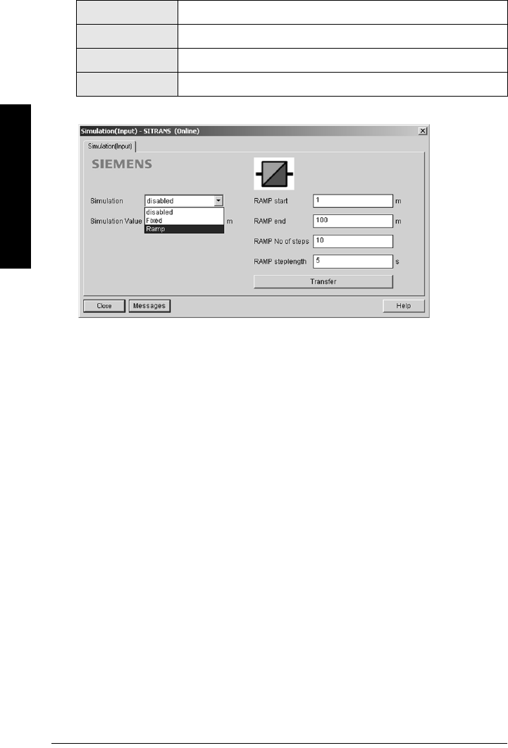
Page 54 SITRANS LR560 (PROFIBUS PA) – OPERATING INSTRUCTIONS 7ML19985LT01
mmmmm
SIMATIC PDM
Simulate Input
Allows you to simulate the sensor value which is input to the Level Transducer Block. This
tests everything between the Level Transducer Block and Output.
1) Open the menu Device – Simulation, and select Simulation (Input).
2) To enable simulation, select Fixed or Ramp.
3) If you select Ramp, enter the step length and number of steps.
4) Enter the simulated value and click on Transfer.
5) After simulation is complete, disable simulation and click on Transfer.
Write Locking
Prevents any changes to parameters via PDM or the hand-held programmer. If Write
Locking is enabled, the data can be viewed but not modified.
To enable/disable Write Protection:
1) Open the menu Device – Write Locking and turn Write Protection On or Off.
2) Click on Transfer.
Ramp start Range: –999999 to 999999. Default: 0
Ramp end Range: –999999 to 999999. Default: 0
Number of steps Range: 0 to 65535. Default: 1
Step length Range: 0 to 65535. Default: 1

7ML19985LT01 SITRANS LR560 (PROFIBUS PA) – OPERATING INSTRUCTIONS Page 55
mmmmm
SIMATIC PDM
Master Reset
To perform a reset to Factory Defaults:
1) Open the menu Device – Master Reset, and click on Factory Defaults.
2) After the reset is complete click on Close, then upload parameters to the PC/PG.
(If you are performing a reset after replacing the device with a different
instrument, do not upload parameters to the PC/PG.)
To reset the PROFIBUS address to 126:
1) Open the menu Device – Master Reset and click on Reset Address to ’126’.
2) Click on OK: the address will be reset to 126, and if the address lock was on, it
will be disabled.
Notes:
• Following a reset, some degree of reprogramming may be required, depending on
the option chosen below.
• While performing any reset, a loss of communications can be expected.
Options Result
Factory
Defaults
Resets all parameters to the manufacturer’s default settings, with certain
exceptions. The list of exceptions includes, but is not limited to:
• Message
•Descriptor
• Installation Date
• Device Address
• Write Protection
• Auto False Echo Suppression Range
• Learned TVT
•Language
Standard
Defaults
Resets all parameters, excluding device addresses and Language, to
the PROFIBUS default settings.
NOTE: After initiating a reset to Standard Defaults via the local user
interface, allow 1-2 minutes before initiating a new command locally.
Informational Resets parameters such as Tag.
Functional Resets parameters that control device behavior, such as Low
Calibration Pt.
Warm Start Has the same effect as recycling power to the device
Device
Address
• Resets the PROFIBUS device address to 126
• If the address lock was on, will disable the lock.
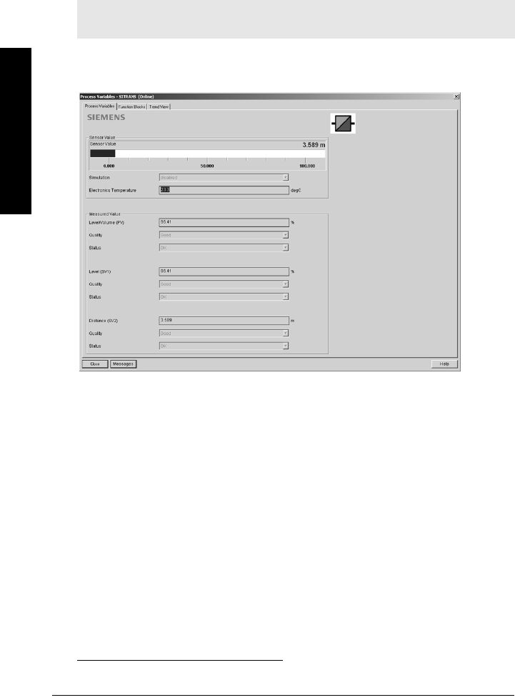
Page 56 SITRANS LR560 (PROFIBUS PA) – OPERATING INSTRUCTIONS 7ML19985LT01
mmmmm
SIMATIC PDM
Diagnostics
You can monitor level/volume trends, function blocks, electronics temperature, and device
status.
Process Variables
To compare outputs in real time open the menu View – Process Variables.
Process Variables
• Sensor Value and simulation setting
• Electronics temperature
• Measured Value (level, volume1), and distance) together with quality and status.
Note: To view peak sensor values, peak FB1 and FB2 values, or peak electronics
temperatures, see
Device Diagnostics
on page 57.
1) Not supported by LR560.
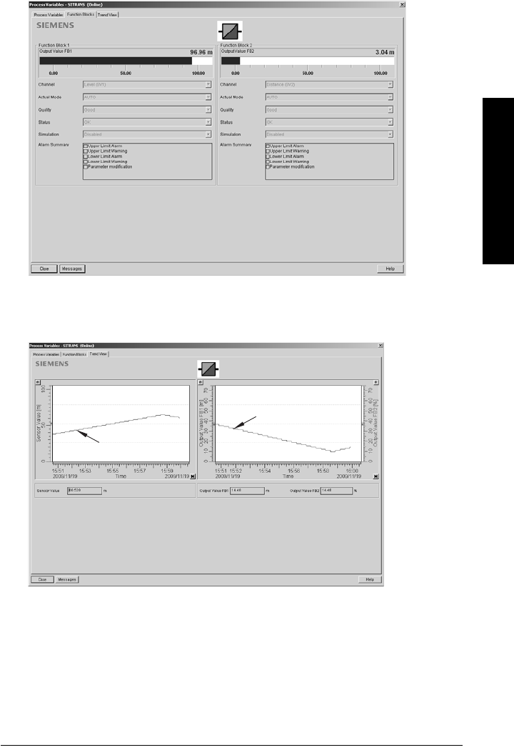
7ML19985LT01 SITRANS LR560 (PROFIBUS PA) – OPERATING INSTRUCTIONS Page 57
mmmmm
SIMATIC PDM
Function Blocks
Open the menu View – Process Variables and click on Function Blocks to view the channel
(level or distance), operating mode (Auto, Manual, or Out of Service), quality, status, simulation
setting, and summary of alarms.
Trend View
Open the menu View – Process Variables and click on Trend View to monitor Sensor Value
and values for AIFB1 and AIFB2.
Device Diagnostics
Device Status
Open the menu View - Device Diagnostics > Device Status to view Diagnostics, Device Status,
Extended Diagnostics, and Maintenance
trend line
trend line
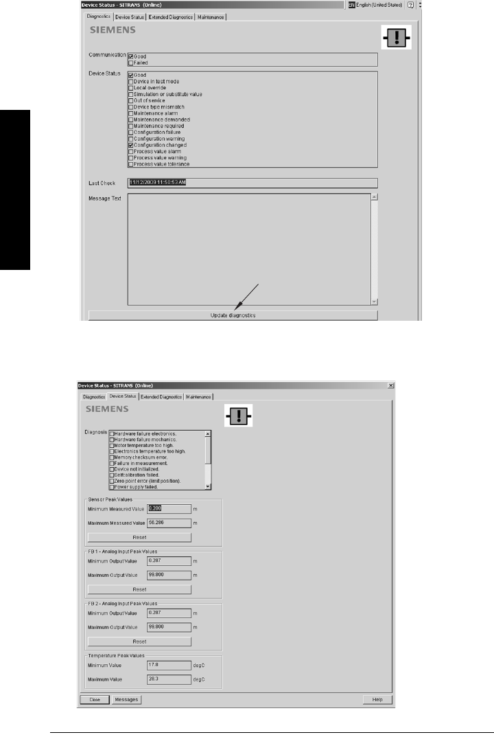
Page 58 SITRANS LR560 (PROFIBUS PA) – OPERATING INSTRUCTIONS 7ML19985LT01
mmmmm
SIMATIC PDM
Diagnostics
In the Device Status window, click on the Diagnostics tab, then on the Update diagnostics
button, to update diagnostic information and refresh linked icons.
Device Status
Click on the Device Status tab to view peak sensor values, peak FB1 and FB2 values, and peak
electronics temperatures.
Update diagnostics
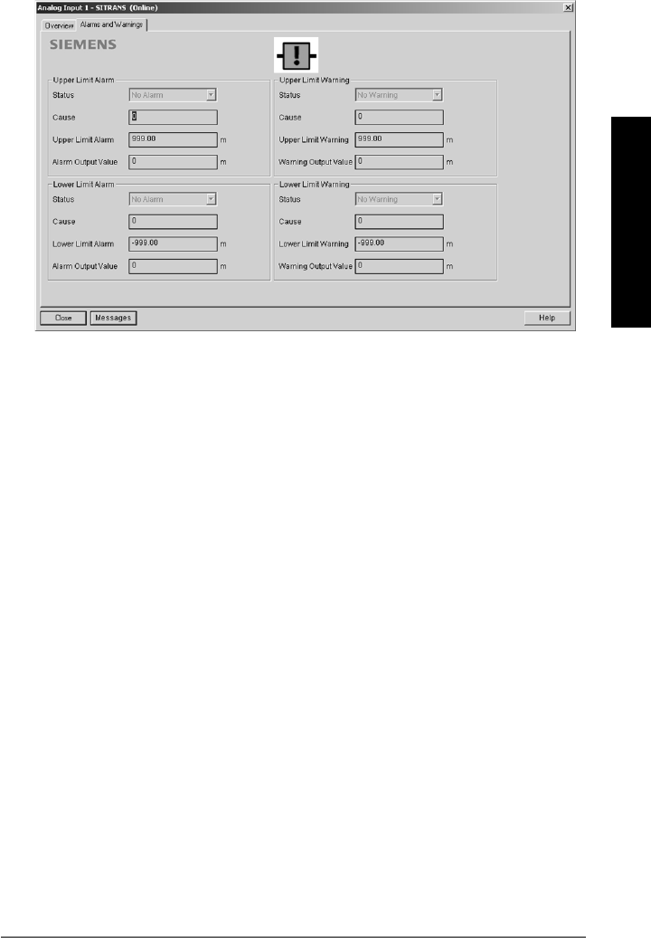
7ML19985LT01 SITRANS LR560 (PROFIBUS PA) – OPERATING INSTRUCTIONS Page 59
mmmmm
SIMATIC PDM
Analog Input 1/Analog Input 2
Open the menu View – Device Diagnostics and go to Analog Input 1/Analog Input 2. Click on
the tab Overview to see the status of all warnings and alarms. Click on the tab Alarms and
Warnings for details.
Update
Open the menu View – Update to refresh the screen.
Security
A password option protects security and communication control parameters from
modification by a maintenance user.
When you open a project the User dialog window provides two options: maintenance or
specialist. If a password has been set it will not be possible to open the project as a specialist
without it. A maintenance user will be able to open the project without a password but will not
have access to security and communication control parameters.
1) Open a project, double-click on the device icon, and in the User window select
Specialist.
2) Open the menu Options – Settings and click on the Password tab.
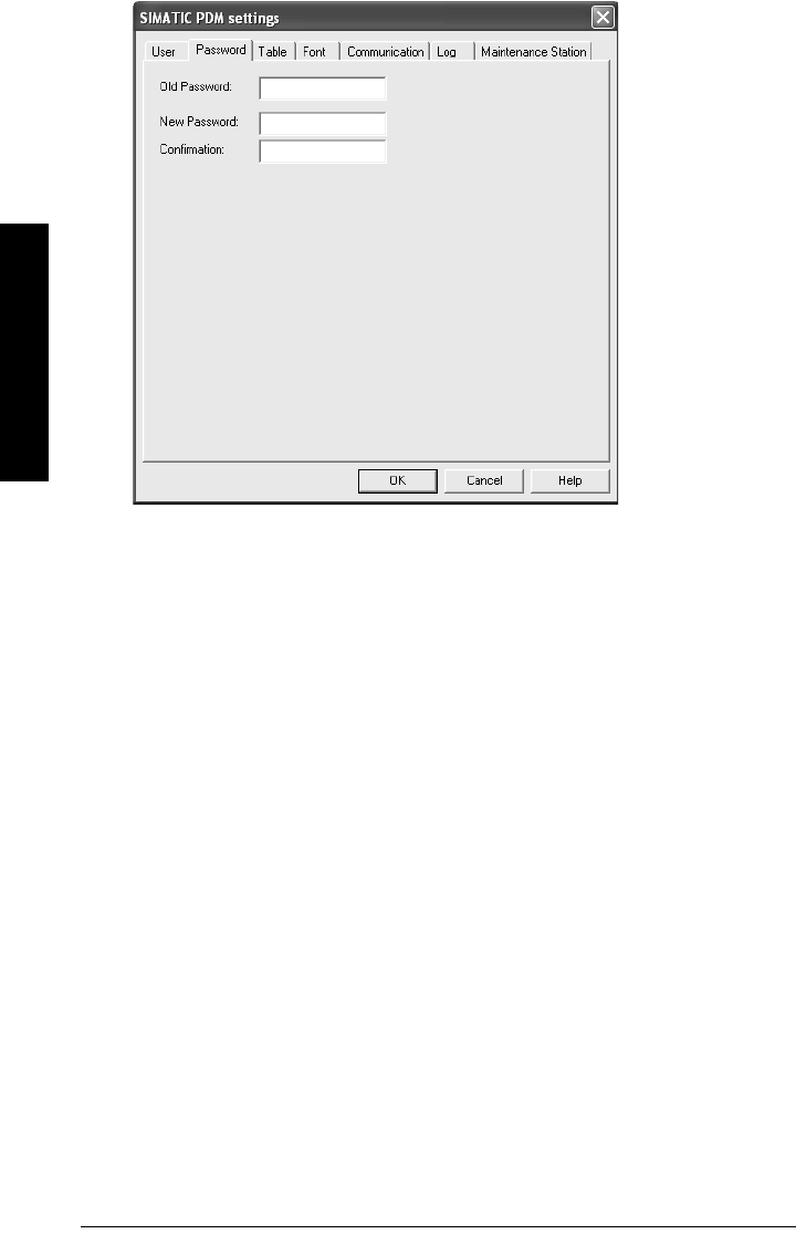
Page 60 SITRANS LR560 (PROFIBUS PA) – OPERATING INSTRUCTIONS 7ML19985LT01
mmmmm
SIMATIC PDM
3) Enter a new password and re-enter it in the Confirmation window. Click on OK.
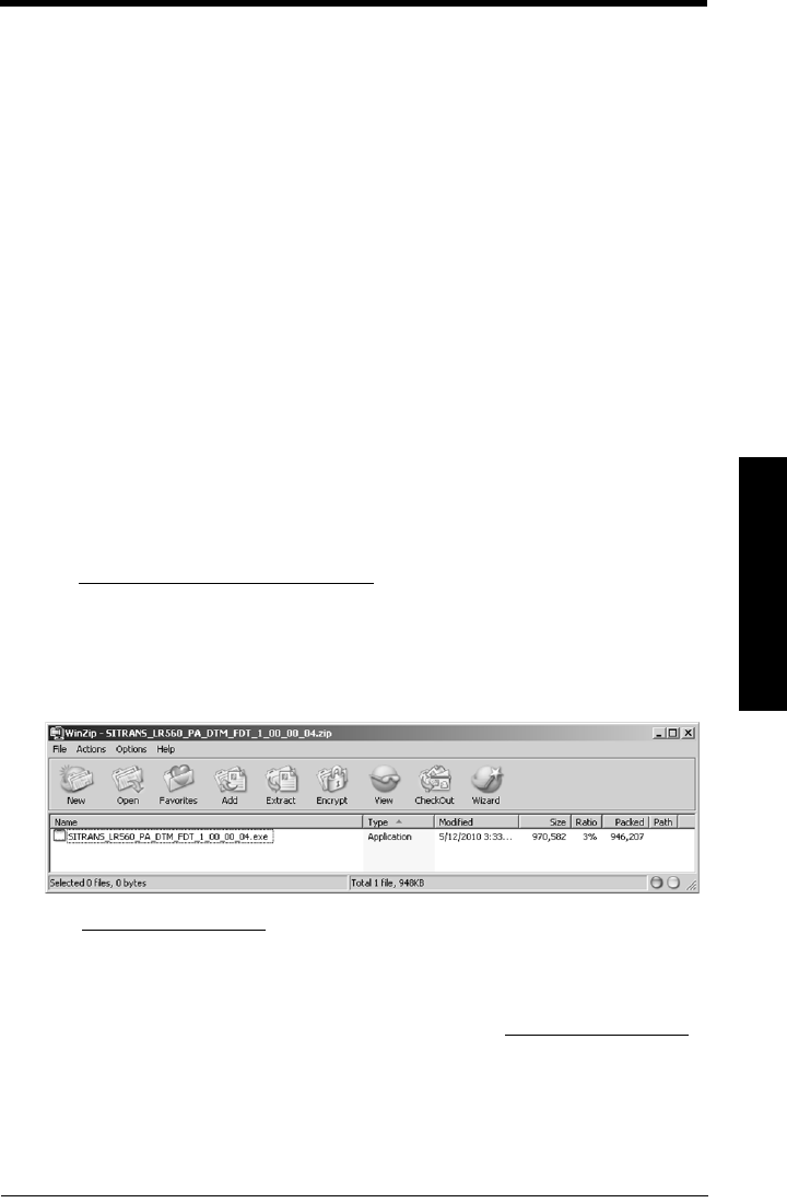
7ML19985LT01 SITRANS LR560 (PROFIBUS PA) – OPERATING INSTRUCTIONS Page 61
mmmmm
FDT: Field Device Tool
Operating via FDT (Field Device Tool)
FDT is a standard used in several software packages designed to commission and maintain
field devices such as SITRANS LR560. Two commercially available FDTs are PACTware and
Fieldcare.
Functionally FDT is very similar to PDM (see
Operating via SIMATIC PDM
on page 39 for more
detail).
• To configure a field device via FDT you need the DTM (Device Type Manager) for the
device.
• To configure a field device via SIMATIC PDM, you need the EDD (Electronic Device
Description) for the device.
Device Type Manager (DTM)
A DTM is a type of software that ’plugs into’ FDT. It contains the same information as an EDD
but an EDD is independent of the operating system.
SITRANS DTM
• SITRANS DTM is an EDDL interpreter developed by Siemens to interpret the EDD
for that device.
• To use SITRANS DTM to connect to an instrument, you must first install
SITRANS DTM on your system and then install the instrument EDD written for
SITRANS DTM.
• You can download SITRANS DTM from the Siemens service and support website at:
http://support.automation.siemens.com. Click on Product Support then go to
Product Information/Process Instrumentation/Software & Communications.
The instrument EDD
The SITRANS LR560 PROFIBUS PA EDD for SITRANS DTM can be downloaded from the
product page of our website.
Go to www.siemens.com/LR560 under Support and click on Software Downloads.
Configuring a new device via FDT
The full process to configure a field device via FDT is outlined in an application guide which
can be downloaded from the product page of our website. Go to: www.siemens.com/LR560
under Support and click on Application Guides.
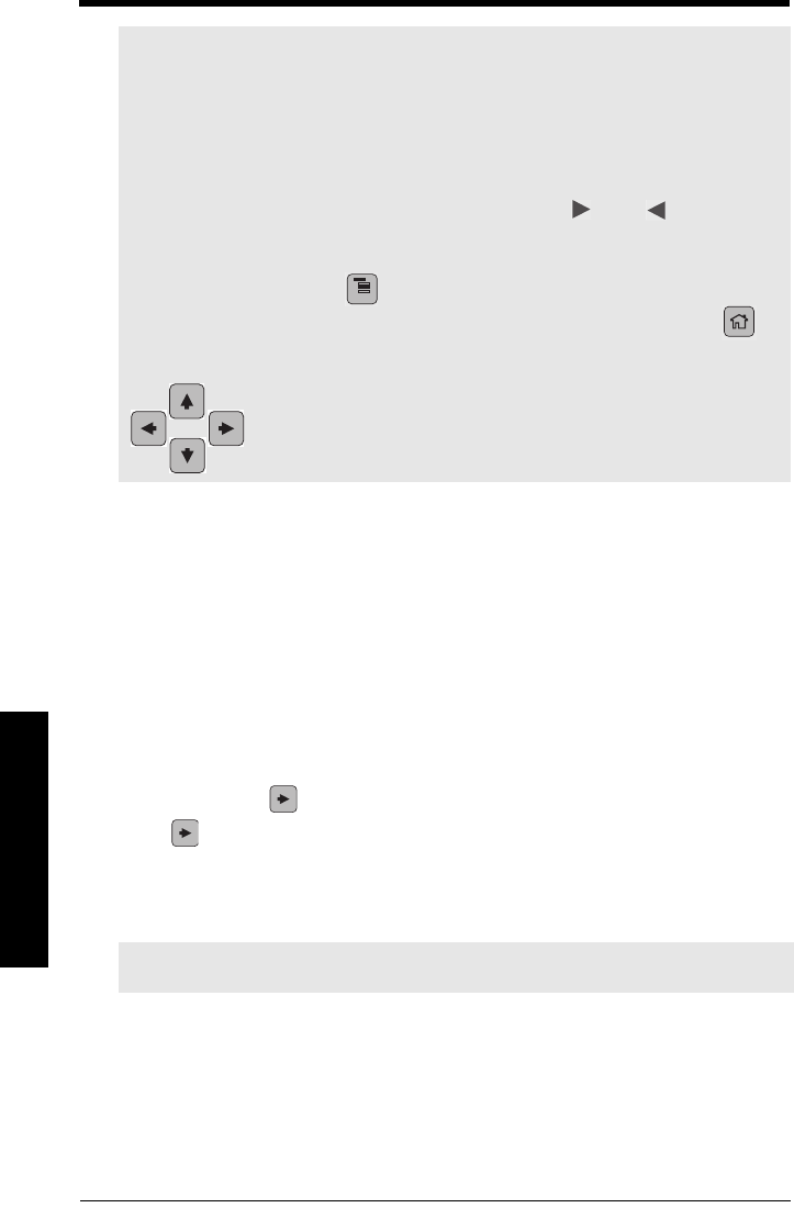
Page 62 SITRANS LR560 (PROFIBUS PA) – OPERATING INSTRUCTIONS 7ML19985LT01
mmmmm
Parameters
Parameter Reference
Parameters are identified by name and organized into function groups. See
LCD menu
structure on page 151
for a chart.
Parameters accessible via the handheld programmer are preceded by a number.
Parameters not preceded by a number are accessible only via remote operation. For
more details see
Operating via SIMATIC PDM on page 39
, or
Operating via FDT (Field
Device Tool) on page 61
.
1. Quick Start
Wizards provide step-by step procedures to configure the device, filter out false echoes,
and upload and download parameters and firmware to the optional display for easy
configuration of multiple LR560s.
Press RIGHT arrow twice to open the Wizards menu. Select a wizard, press RIGHT
arrow to open the first step, and follow the instructions.
1.1. Quick Start Wizard
The Quick Start wizard provides an easy step-by-step procedure to configure the device
for a simple application.
•See
Quick Start Wizard via the LDI push buttons on page 34
.
•See
Quick Start Wizard via the handheld programmer on page 34
.
•See
Quick Start Wizard via SIMATIC PDM on page 40
.
Notes:
• Parameter names and menu structure are similar but not identical for SIMATIC PDM
and the local display (LCD). This chapter follows the LCD menu structure, and the
navigation path is provided to parameters that have a different location in
SIMATIC PDM.
• Default settings in the parameter tables are indicated with an asterisk (*) unless
explicitly stated.
• To enter Program mode using the device buttons, press . Press to return to
Measurement mode.
• To enter PROGRAM mode/return to Measurement mode via the handheld
programmer, press Mode .
• For Quick Access to parameters via the handheld programmer, press Home ,
then enter the menu number, for example: 2.2.1.
Note: Do not use the Quick Start wizard to modify individual parameters. (Perform cus-
tomization only after the Quick Start has been completed.)
• In Navigation mode, ARROW keys navigate the menu in the
direction of the arrow.
• Press RIGHT Arrow to open Edit Mode, or to save a modification.
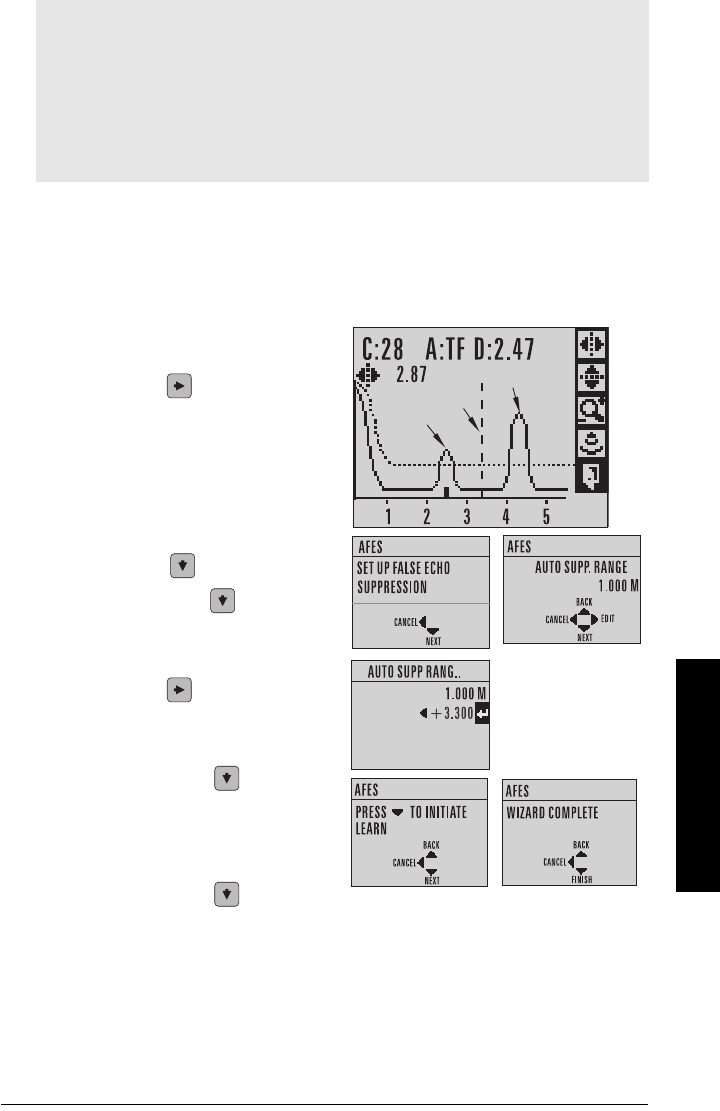
7ML19985LT01 SITRANS LR560 (PROFIBUS PA) – OPERATING INSTRUCTIONS Page 63
mmmmm
Parameters
1.2. AFES (Auto False Echo Suppression) Wizard
If you have a vessel with known obstructions, we recommend using AFES to prevent false
echo detection.
This feature can also be used if SITRANS LR560 displays a false high level, or the reading
is fluctuating between the correct level and a false high level.
a) Make sure the material level is below all known obstructions.
b) Navigate to Level Meter > Diagnostics
(3.) > Echo Profile (3.1.) and press
RIGHT arrow to request a profile.
c) Determine a range that includes the
false echo but not the true echo: in the
example, 3.3 m.
d) Open the AFES wizard and press
DOWN arrow to continue.
e) Press RIGHT arrow to edit Auto
False Echo Suppression Range.
f) Enter the new range value and press
RIGHT arrow to transfer it.
g) Press DOWN arrow to initiate
Learn. A transition screen appears,
followed by the message Wizard
Complete.
h) Press DOWN arrow (Finish) to
save AFES parameter changes and return to Program menu.
(continued on next page)
Notes:
• Before using AFES, configure the device via the Quick Start wizard.
• Make sure material level is below all known obstructions at the moment Auto False
Echo Suppression is used to learn a custom TVT (Time Varying Threshold). We
recommend an empty or almost empty vessel.
• Note the distance to material level when the environment is learned, and set Auto
False Echo Suppression Range to a shorter distance to avoid the material echo being
screened out.
false
echo
true echo
AFES range
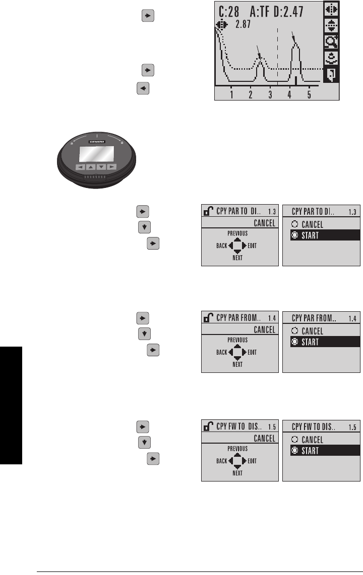
Page 64 SITRANS LR560 (PROFIBUS PA) – OPERATING INSTRUCTIONS 7ML19985LT01
mmmmm
Parameters
i) Navigate to Echo Profile (3.1.) and
press RIGHT arrow to request a
profile. The false echo is now
screened out and the true echo
selected. With Exit icon selected,
press RIGHT arrow to exit.
j) Press LEFT arrow twice to return
to Measurement mode
1.3. Copy Parameters to Display
Transfers parameter settings from a device to the local display interface.
PARAM UPLOAD is displayed, then the device returns to Measurement mode.
1.4. Copy Parameters from Display
Transfers parameter settings from the local display interface to a device.
PARAM DOWNLOAD is displayed, then the device returns to Measurement mode.
1.5. Copy Firmware to Display
Transfers firmware from a device to the local display interface.
SW UPLOAD is displayed during the transfer, then the device returns to Measurement
mode.
true echo
false echo
See
Connecting SITRANS LR560 on page 23
for instructions on
removing the local display interface.
• Press RIGHT arrow to Edit.
•Press DOWN arrow to select
Start and RIGHT arrow to begin
the transfer.
• Press RIGHT arrow to Edit.
•Press DOWN arrow to select
Start and RIGHT arrow to begin
the transfer.
• Press RIGHT arrow to Edit.
•Press DOWN arrow to select
Start and RIGHT arrow to begin
the transfer.

7ML19985LT01 SITRANS LR560 (PROFIBUS PA) – OPERATING INSTRUCTIONS Page 65
mmmmm
Parameters
1.6. Copy Firmware from Display
Transfers firmware from the local display interface to a device.
SW DOWNLOAD is displayed at the beginning of the transfer. This is followed first by a
blank screen (for approximately 2 minutes), then by a progress indicator, and then by the
Siemens logo with the LOE icon. When the transfer is complete,the device returns to
Measurement mode.
2. Setup
2.1. Identification
2.1.1. Tag
Text that can be used in any way. A recommended use is as a unique label for
a field device in a plant. Limited to 32 ASCII characters.
2.1.2. Descriptor
Text that can be used in any way. Limited to 32 ASCII characters. No specific
recommended use.
2.1.3. Message
Text that can be used in any way. Limited to 32 ASCII characters. No specific
recommended use.
2.1.4. Installation Date
Date the device was first commissioned (text string, no format restrictions).
2.2. Device
2.2.1. Hardware Revision
Read only. Corresponds to the electronics hardware of the Field Device.
2.2.2. Firmware Revision
Read only. Corresponds to the software or firmware that is embedded in the
Field Device.
2.2.3. Loader Revision
Read only. Corresponds to the software used to update the Field Device.
Note: Do not interrupt power supply during transfer.
Notes:
• Default settings in the parameter tables are indicated with an asterisk (*) unless
explicitly stated.
• Values shown in the following tables can be entered via the handheld programmer.
Note: SITRANS PDM limits the TAG field to a maximum of 24 characters.
• Press RIGHT arrow to Edit.
•Press DOWN arrow to select
Start and RIGHT arrow to begin
the transfer.
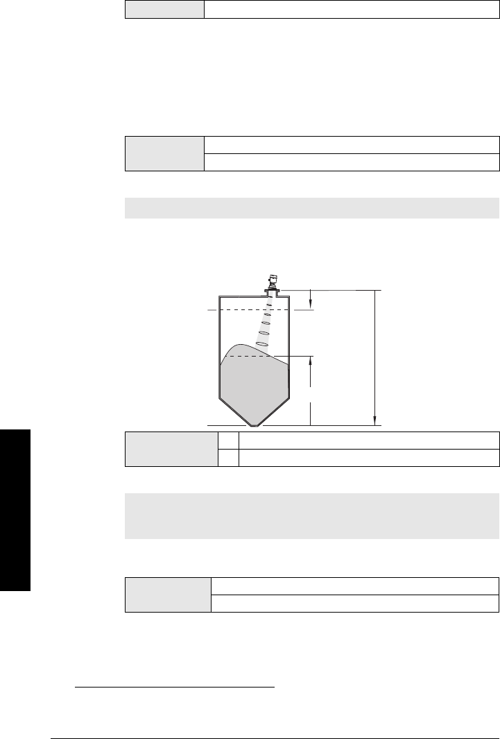
Page 66 SITRANS LR560 (PROFIBUS PA) – OPERATING INSTRUCTIONS 7ML19985LT01
mmmmm
Parameters
2.2.4. Menu timeout
Time menu stays visible before switching back to Measurement view if no key
is pressed.
2.2.5. Manufacturing Date
The date of manufacture of the SITRANS LR560 (YYYYMMDD).
2.3. Sensor
2.3.1. Unit
Sensor measurement unit. Used in setting High/Low Calibration Point, and
displayed on LCD and in PDM.
2.3.2. Level Unit
The engineering unit used for Level. High Level Point corresponds to High
Calibration Pt. (2.3.5.2.) and Low Level Point corresponds to Low Level Point
(2.3.5.4.).
1)
2.3.3. LOE Timer
Sets the time to elapse since the last valid reading, before the Fail-safe material
level is reported.
Values Range: 15 to 65535 s. Default: 120 s
Values m, cm, mm, ft, in
Default: m
Note: We recommend leaving Level Unit set to %.
Options m, cm, mm, ft, in, %
*%
1) The point on the sensor from which measurements are referenced (see
Dimensions
on page 12
).
Note: When a Loss of Echo occurs Value (2.5.9.2.) determines the material
level to be reported when LOE Timer expires. See
Loss of Echo (LOE) on page
121
for more detail.
Values Range: 0 to 720 seconds
Default: 100 s
High Level Point
(default: 100%)
Low Level Point
(default: 0%)
Level Low
Calibration
High
Calibration
sensor
reference
point1)
(flange face)
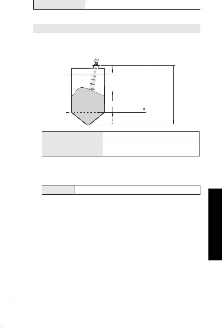
7ML19985LT01 SITRANS LR560 (PROFIBUS PA) – OPERATING INSTRUCTIONS Page 67
mmmmm
Parameters
2.3.4. Temperature Unit
Selects the engineering unit to be displayed with the value representing
temperature..
2.3.5. Calibration
2.3.5.1. Low Calibration Pt.
Distance from sensor reference point
1)
to Low Calibration Point. Unit is
defined in Unit (2.3.1.) and displayed on the LCD and in PDM.
2.3.5.2. High Calibration Pt.
Distance from Sensor Reference to High Calibration Point. Unit is defined in
Unit (2.3.1.) and displayed on the LCD and in PDM.
When setting the High Calibration Point value, note that echoes are
ignored within Near Range (2.4.1.)
Options Degrees C, F, R, or K. Default: Degrees C
Note: We recommend using the Quick Start wizard to configure the device.
1) The point on the sensor from which measurements are referenced (see
Dimensions
on page 12
.
Values Range: 0 to 100 m. Default: 100.00 m
Related parameters Unit (2.3.1.)
Far Range (2.4.2.)
Values Range: 0 to 100 m. Default: 0.000 m
High Level Point
(default: 100%)
sensor
reference
point
Low Level Point
(default: 0%)
Level Low
Calibration
Point
High
Calibration
Point
Far
Range
Level Offset
(if used)

Page 68 SITRANS LR560 (PROFIBUS PA) – OPERATING INSTRUCTIONS 7ML19985LT01
mmmmm
Parameters
2.3.5.3. Sensor Offset
A constant offset (negative or positive) that can be added to sensor value
1)
to compensate if the sensor reference point has shifted. (For example, this
could result from adding a thicker gasket or reducing the standoff/nozzle
height.) The units are defined in Unit (2.3.1.).
2.3.5.4. Low Level Point
The level when the material is at Low Calibration Point. The unit is defined
in Level Unit (2.3.2.).
2.3.5.5. High Level Point
The level when the material is at High Calibration Point. The unit is defined
in Level Unit (2.3.2.).
2.3.5.6. Level Offset
A constant offset that can be added to Level. The unit is defined in Level
Unit (2.3.2.).
2.3.6. Rate
2.3.6.1. Response Rate
Sets the reaction speed of the device to measurement changes.
.
Use a setting just faster than the maximum filling or emptying rate
(whichever is greater).
1) The distance from sensor reference point to target (see
Minimum Sensor Value 2.4.3.
on page 70
for an illustration.
Values Range: -100 to 100. Default: 0 m
Related parameters Unit (2.3.1.)
Values Range: -999999 to 999999.
Default: 0%
Values Range: -999999 to 999999.
Default: 100%
Values Range: -999999 to 999999.
Default: 0%
Note: Default settings in the parameter tables are indicated with an asterisk
(*) unless explicitly stated.
Notes:
• Changing Response Rate resets Fill Rate/Min (2.3.6.2.), Empty rate/
Min (2.3.6.3.), and Filter Time Constant (2.5.8.1.).
• Selecting SLOW changes setting for Average amount (2.8.3.) to 0.9.
Response Rate
(2.3.6.1.)
Fill Rate/Min (2.3.6.2.)/
Empty rate/Min (2.3.6.3.)
Filter Time Constant
(2.5.8.1.)
Slow 0.1 m/min (0.32 ft/min) 10 s
* Medium 1.0 m/min (3.28 ft/min) 10 s
Fast 10.0 m/min (32.8 ft/min) 0 s

7ML19985LT01 SITRANS LR560 (PROFIBUS PA) – OPERATING INSTRUCTIONS Page 69
mmmmm
Parameters
2.3.6.2. Fill Rate/Min
Defines the maximum rate at which the reported sensor value is allowed to
increase. Allows you to further adjust the SITRANS LR560 response to
increases in the actual material level. Fill Rate is automatically updated
whenever Response Rate (2.3.6.1.) is altered.
Enter a value slightly greater than the maximum vessel-filling rate, in units
per minute.
2.3.6.3. Empty rate/Min
Defines the maximum rate at which the reported sensor value is allowed to
decrease. Adjusts the SITRANS LR560 response to decreases in the actual
material level. Empty Rate is automatically updated whenever Response
Rate (2.3.6.1.) is altered.
Enter a value slightly greater than the vessel’s maximum emptying rate, in
units per minute.
2.4. Signal Processing
2.4.1. Near Range
The range in front of the device (measured from the sensor reference point
1)
)
within which any echoes will be ignored. (This is sometimes referred to as
"Blanking" or "Dead Zone".)
Options
Range: 0 to 999999 m / min.
Response Rate (2.3.6.1.) Fill Rate
Slow 0.1 m/min (0.32 ft/min)
* Medium 1.0 m/min (3.28 ft/min)
Fast 10.0 m/min (32.8 ft/min)
Related parameters Level Unit (2.3.2.)
Options
Range: 0 to 999999 m / min.
Response Rate (2.3.6.1.) Empty Rate
Slow 0.1 m/min (0.32 ft/min)
* Medium 1.0 m/min (3.28 ft/min)
Fast 10.0 m/min (32.8 ft/min)
Related parameters Level Unit (2.3.2.)
Note: Default settings in the parameter tables are indicated with an asterisk (*)
unless explicitly stated.
1) Flange face: see
Dimensions on page 12
.
Values Range: 0 to 105 m (0 to 344.5 ft)
Default: 0.278 m (0.91 ft)
Related parameters Unit (2.3.1.)
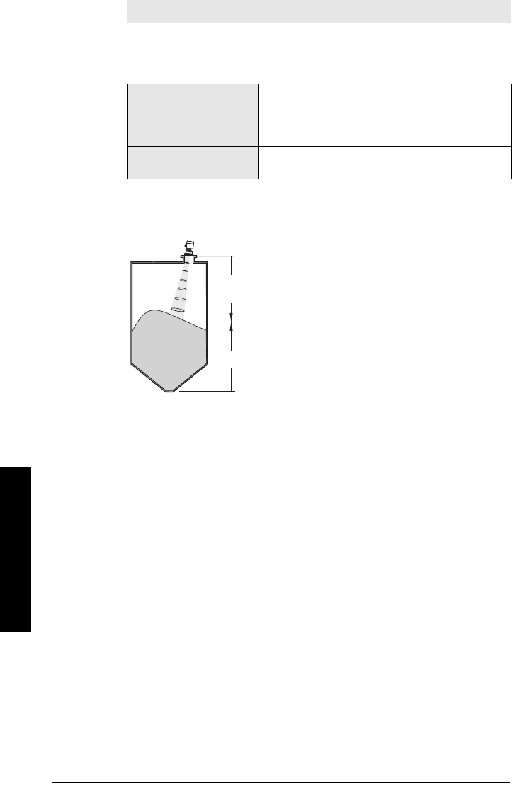
Page 70 SITRANS LR560 (PROFIBUS PA) – OPERATING INSTRUCTIONS 7ML19985LT01
mmmmm
Parameters
2.4.2. Far Range
Allows the material level to drop below Low Calibration Point without
generating a Loss of Echo (LOE) state. See Low Calibration Pt. (2.3.5.1.) on page
67 for an illustration.
Use this feature if the measured surface can drop below Low Calibration Point
in normal operation. See
Far Range (2.4.2.) on page 120
for more detail.
2.4.3. Minimum Sensor Value
Read Only. Defines the minimum usable value for the measuring range, in units
defined in Unit (2.3.1.).
(Default = 0.0 m)
• Open the menu View – Device Diagnostics > Device Status, and click on
the Device Status tab.
• Check Sensor Peak Values.
2.4.4. Maximum Sensor Value
Read Only. Defines the minimum usable value for the measuring range, in units
defined in Unit (2.3.1.).
(Default : 105 m for 100 m device, 45 m for 40 m device)
• Open the menu View – Device Diagnostics > Device Status, and click on
the Device Status tab.
• Check Sensor Peak Values.
Note: Far Range can extend beyond the bottom of the vessel.
Values
Range: Min. = Low Calibration Pt.
Max. = 45 m (131.2 ft): 40 m device
= 105 m (344.5 ft): 100 m device
Default: Value for Low Calibration Pt. + 5 m (16.4 ft)
Related parameters Unit (2.3.1.)
CLEF Range (2.4.5.4.)
sensor value (distance from sensor reference point
to the target)
sensor reference point (flange face)
Level

7ML19985LT01 SITRANS LR560 (PROFIBUS PA) – OPERATING INSTRUCTIONS Page 71
mmmmm
Parameters
2.4.5. Echo select
2.4.5.1. Algorithm
Selects the algorithm to be applied to the echo profile to extract the true
echo.
2.4.5.2. Position Detect
Defines where on the echo the distance measurement is determined. See
Position Detect (2.4.5.2.) on page 116 for more detail.
If the vessel bottom is being reported as the level instead of the actual
material level (at low level conditions) we recommend setting Position
Detect to Hybrid and using it in combination with CLEF Range (2.4.5.4.).
Options
ALF Area Largest First
AEcho Area
L Largest echo
* F First Echo
AL Area Largest
AF Area First
LF Largest First
BLF Best F-L (First and Largest)
BL Best L (Largest)
BF Best F (First)
Last
TF true First echo
Note: Selecting Steel or Concrete vessel type in the Quick Start wizard
changes the setting for Position Detect (2.4.5.2.) to Rising Edge.
Options
*Rising Edge (yields highest stability on sloped
targets)
Center (yields higher accuracy on flat, non-
sloped targets)
Hybrid (Center and CLEF)
CLEF (Constrained Leading Edge Fit)
Related parameters CLEF Range (2.4.5.4.)
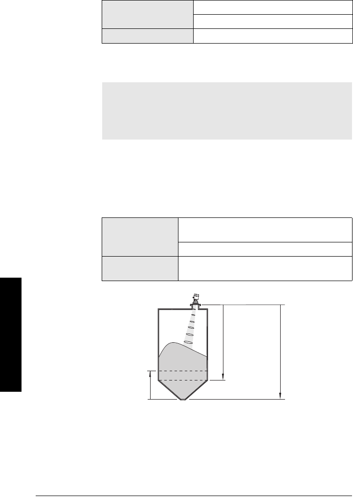
Page 72 SITRANS LR560 (PROFIBUS PA) – OPERATING INSTRUCTIONS 7ML19985LT01
mmmmm
Parameters
2.4.5.3. Echo Threshold
Sets the minimum echo confidence that the echo must meet in order to
prevent a Loss of Echo condition and the expiration of the LOE timer. When
Confidence (2.4.7.1.) exceeds Echo Threshold (2.4.5.3.), the echo is
accepted as a valid echo and is evaluated.
Use this feature when an incorrect material level is reported.
2.4.5.4. CLEF Range
The CLEF algorithm is used mainly to allow correct level reporting for low
dK materials which may otherwise cause an incorrect reading in an empty
or almost empty vessel.
It is used from Far Range up to the level defined by CLEF Range (see
illustration below). Above that point the Center algorithm is used. For more
detail see CLEF Range (2.4.5.4.) on page 118 .
Values Range: 0 to 99
Default: 5
Related Parameters LOE Timer (2.3.3.)
Notes:
• CLEF Range is referenced from Far Range.
• The value for CLEF Range must include the difference between Far
Range and Low Calibration Point, plus any level above the Low
Calibration Point to be managed by the CLEF algorithm.
Values
Range: 0 to 45 m (40 m device)
0 to 105 m (100 m device)
Default: 0.0 m
Related parameters Position Detect (2.4.5.2.)
Far Range (2.4.2.)
sensor
reference
point
CLEF Range Low Calibration
Point
Far
Range

7ML19985LT01 SITRANS LR560 (PROFIBUS PA) – OPERATING INSTRUCTIONS Page 73
mmmmm
Parameters
2.4.5.5. Echo Marker
The point on the primary echo on which the measured value is based.
Use this feature if the reported material level fluctuates slightly, due to a
variable rise in the leading edge of the true echo on the Echo Profile.
Enter the value (in percent of echo height) to ensure the Echo Lock
Window intersects the Echo Profile at the sharpest rising portion of the
Echo Profile representing the true echo. This value is preset to 70%.
2.4.6. Sampling
Provides a method of checking the reliability of a new echo before accepting it
as the valid reading, based on numbers of samples above or below the
currently selected echo.
2.4.6.1. Echo Lock
Selects the measurement verification process.
For radar applications, Material Agitator is the most often used setting, to
avoid agitator blade detection.
2.4.6.2. Sampling up
Specifies the number of consecutive echoes that must appear above the
echo currently selected, before the measurement is accepted as valid.
2.4.6.3. Sampling down
Specifies the number of consecutive echoes that must appear below the
echo currently selected, before the measurement is accepted as valid.
Values Range: 5 to 95%
Default: 70%
Options
Lock Off (no verification)
Maximum Verification (not recommended for radar)
* Material Agitator
Total Lock (not recommended for radar)
Related
parameters
Fill Rate/Min (2.3.6.2.)
Empty rate/Min (2.3.6.3.)
Sampling up (2.4.6.2.)
Sampling down (2.4.6.3.)
Values Range: 1 to 50
Default: 5
Values Range: 1 to 50
Default: 2

Page 74 SITRANS LR560 (PROFIBUS PA) – OPERATING INSTRUCTIONS 7ML19985LT01
mmmmm
Parameters
2.4.6.4. Echo Lock Window
A “distance window” centered on the echo
1)
is used to derive the reading.
When a new measurement is in the window, the window is re-centered
and the reading is calculated.
When the value is 0, the window is automatically calculated after each
measurement.
• For slower Measurement Response values, the window is narrow.
• For faster Measurement Response values, the window becomes
progressively wider.
2.4.7. Echo Quality
2.4.7.1. Confidence
Indicates echo reliability: higher values represent better echo quality. The
display shows the echo confidence of the last measurement. Echo
Threshold (2.4.5.3.) defines the minimum criterion for echo confidence.
Open the menu Device – Echo Profile Utilities and click on the tab Echo
Profile.
2.4.7.2. Echo Strength
Displays the absolute strength (in dB above 1 μV rms) of the echo selected
as the measurement echo.
Open the menu Device – Echo Profile Utilities and click on the tab Echo
Profile.
1) See
Echo Lock (2.4.6.1.)
on page 118 for more detail.
Values Range: 0 to 105 m
Default: 0 m
Note: The Echo Lock window is stored as a standard sample, but
displayed in sensor units. Any value entered for the Echo Lock window
will be rounded to the nearest sample.
Values (view only) 0 to 99
---- Shot not used
Related Parameters Echo Threshold (2.4.5.3.)
Values (view only) –20 to 99
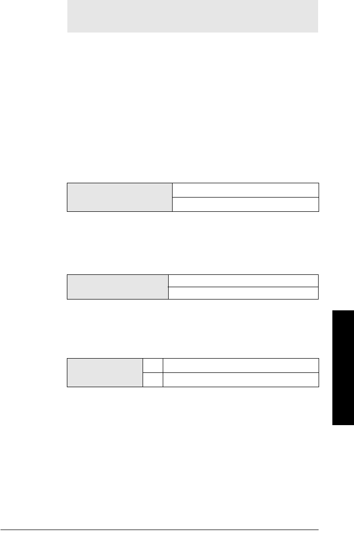
7ML19985LT01 SITRANS LR560 (PROFIBUS PA) – OPERATING INSTRUCTIONS Page 75
mmmmm
Parameters
2.4.8. TVT setup
2.4.8.1. Auto False Echo Suppression
Used together with Auto False Echo Suppression Range (2.4.8.2.) to screen
out false echoes in a vessel with known obstructions.A ’learned TVT’ (time
varying threshold) replaces the default TVT over a specified range.
•See
Auto False Echo Suppression (2.4.8.1.) on page 118
for a more
detailed explanation.
• To set via SIMATIC PDM see
Auto False Echo Suppression on page
48
.
• To set via local operation see
AFES (Auto False Echo Suppression)
Wizard 1.2. on page 63
.
2.4.8.2. Auto False Echo Suppression Range
Defines the e ndpoint of the Learned TVT distance. Units are defined in Unit
(2.3.1.). Used in combination with Auto False Echo Suppression (see above).
2.4.8.3. Hover Level
Defines how high the TVT (Time Varying Threshold) is placed above the
noise floor of the echo profile, as a percentage of the difference between
the peak of the largest echo in the profile and the noise floor. (See Before
Auto False Echo Suppression on page 49 for an illustration.
)
When the device is located in the center of the vessel, the TVT hover level
may be lowered to increase the confidence level of the largest echo.
2.4.8.4. Shaper Mode
Enables/disables TVT shaper (2.4.9.).
Note: We recommend setting Auto False Echo Suppression either viaSI-
MATIC PDM or via local operation using the Auto False Echo Suppres-
sion wizard.
Values Range: 0.00 to105.00 m
Default: 1.00 m
Values Range: 0 to 100%
Default: 40%
Options *OFF
ON

Page 76 SITRANS LR560 (PROFIBUS PA) – OPERATING INSTRUCTIONS 7ML19985LT01
mmmmm
Parameters
2.4.9. TVT shaper
Adjusts the TVT (Time Varying Threshold) at a specified range (breakpoint on
the TVT). This allows you to reshape the TVT curve to avoid unwanted echoes.
There are 120 breakpoints.
To use TVT shaper via SIMATIC PDM:
Open the menu Device – Echo Profile Utilities and click on the tab TVT Shaper
(see
TVT Shaper on page 47
for more details).
To use TVT shaper via the local display interface (LDI):
a) Go to Shaper Mode (2.4.8.4.) and select option ON.
b) In TVT shaper, go to Breakpoint 1-9 (2.4.9.1.).
c) Open Breakpoint 1 and enter the TVT Offset value (between –50 and 50).
d) Go to the next Breakpoint and repeat step (c) till all desired breakpoint
values have been entered.
2.4.9.1. Breakpoint 1-9
2.4.9.2. Breakpoint 10-18
2.4.9.3. Breakpoint 19-27
2.4.9.4. Breakpoint 28-36
2.4.9.5. Breakpoint 37-45
2.4.9.6. Breakpoint 46-54
2.4.9.7. Breakpoint 55-63
2.4.9.8. Breakpoint 64-72
2.4.9.9. Breakpoint 73-81
2.4.9.10. Breakpoint 82-90
2.4.9.11. Breakpoint 91-99
2.4.9.12. Breakpoint 100-108
2.4.9.13. Breakpoint 109-117
2.4.9.14. Breakpoint 118-120
Notes:
•Shaper Mode (2.4.8.4.) must be turned ON in order for TVT shaper
breakpoints to be transferred.
• We recommend using SIMATIC PDM to access this feature.
Values Range: –50 dB to +50 dB
Default: 0
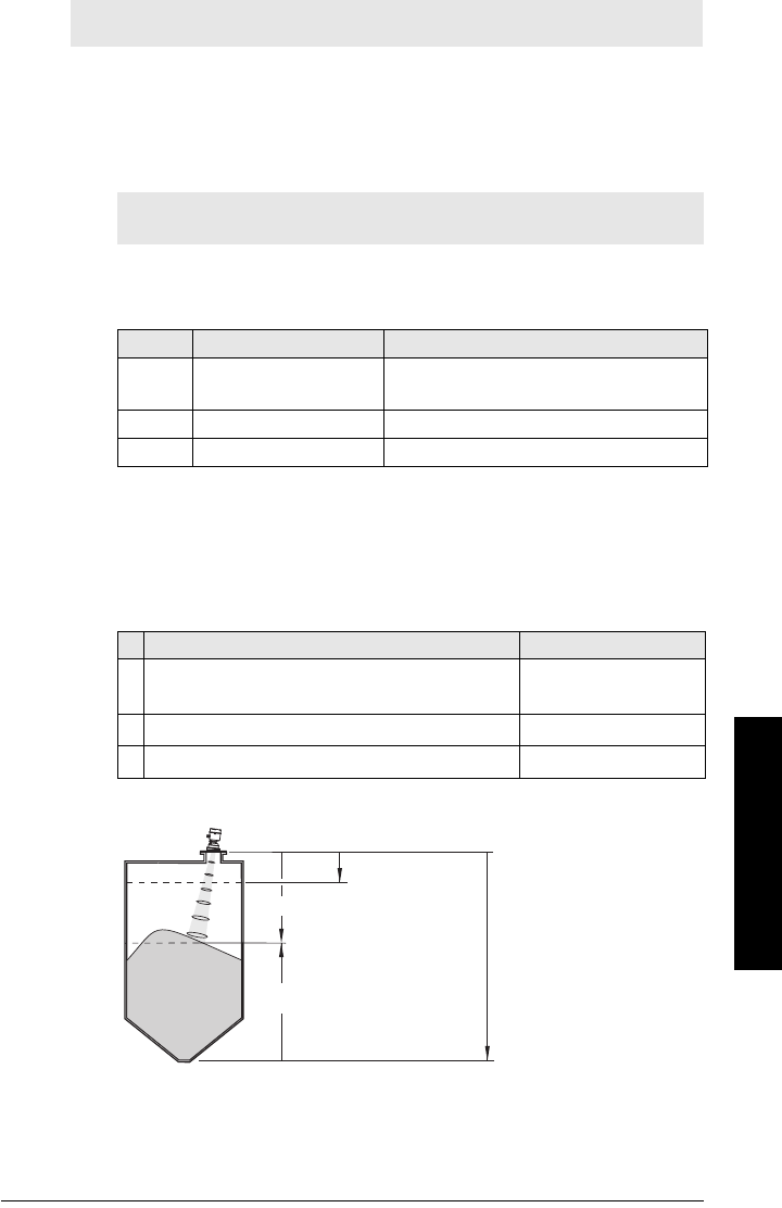
7ML19985LT01 SITRANS LR560 (PROFIBUS PA) – OPERATING INSTRUCTIONS Page 77
mmmmm
Parameters
2.5. AIFB1
2.5.1. Static Revision No.
The revision level of the static data associated with Analog Input Function
Block 1. The Static Revision No. is updated whenever a configuration
parameter is changed.
2.5.2. Mode
Used to request an operating mode from the Analog Input Function Block.
Allows you to put SITRANS LR560 into Manual mode (used in conjunction with
Simulation) or Out-of-Service mode for maintenance purposes.
We recommend using this parameter only with SIMATIC PDM in order to
benefit from all the features available. For a detailed explanation see
AIFB
(simulation, mode and status) on page 127
.
To use Mode via PDM see
Simulate Output on page 53
.
2.5.3. Channel
Used to select the Transducer Block output.
Note: Default settings in the parameter tables are indicated with an asterisk (*)
unless explicitly stated.
Note: Ensure that Mode is returned to AUTO when simulation or mainte-
nance are completed.
Setting Description Output value
AUTO automatic the automatically-recorded measured
value
MAN manual a manually-set fixed simulation value
O/S function block disabled the preset safety value
Options Reference Point
Level/Volume (PV - Primary Valuea)). Note: Volume is
a standard option, but not supported by LR560 PA.
a) See
Transducer Block on page 125
for an illustration.
Low Calibration Point
Level (SV1 - Secondary Value 1a))Low Calibration Point
*Distance (SV2 - Secondary Value 2a))sensor reference point
Low Calibration Point
(process empty level)
Level
Distance
sensor reference point
High Calibration
Point
(process full level)
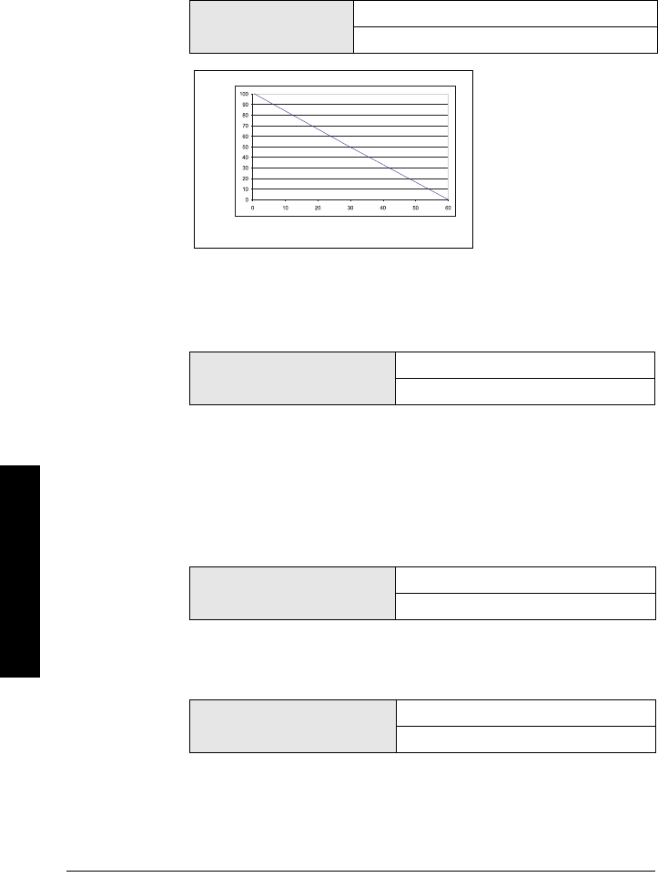
Page 78 SITRANS LR560 (PROFIBUS PA) – OPERATING INSTRUCTIONS 7ML19985LT01
mmmmm
Parameters
2.5.4. Label
User defined label.
2.5.5. Input Scaling
2.5.5.1. Upper Value
Defines the operational upper range value of the input value (Process
Value Scale) in PV (volume/level) Units. Process Value Scale normalizes
the input value to a customer-defined range.
2.5.5.2. Lower Value
Defines the operational lower range value of the input value (Process Value
Scale) in PV (volume/level) Units. Process Value Scale normalizes the input
value to a customer-defined range.
2.5.6. Output Scaling
Scales the Process Variable. The function block parameter OUT SCALE
contains the values of the lower limit and upper limit effective range in AIFB1
units.
2.5.6.1. Upper Value
Defines the operational upper range value of the output value in AIFB1
units.
2.5.6.2. Lower Value
Defines the operational lower range value of the output value in AIFB1
units.
Values Range: -999999 to 999999
Default: 100%
Values Range: -999999 to 999999
Default: 0%
Values Range: -999999 to 999999
Default: 100%
Values Range: -999999 to 999999
Default: 0%
Process Value Scale Input
(typically 0 to 100%)
Output Scale
Provides output
values (Out) to
AIFB1 or AIFB2

7ML19985LT01 SITRANS LR560 (PROFIBUS PA) – OPERATING INSTRUCTIONS Page 79
mmmmm
Parameters
2.5.7. Alarms and Warnings
2.5.7.1. High Limit Alarm
The setting for the upper alarm limit in AIFB1 units.
2.5.7.2. High Limit Warning
The setting for the upper warning limit in AIFB1 units
2.5.7.3. Low Limit Warning
The setting for the lower warning limit in AIFB1 units.
2.5.7.4. Low Limit Alarm
The setting for the lower alarm limit in AIFB1 units.
2.5.7.5. Limit Hysteresis
Hysteresis is used to adjust the sensitivity of the trigger for alarm
messages. It is used to compensate when a process variable fluctuates
around the same value as a limit. A high level alarm occurs when a value
exceeds an upper limit. The alarm’s status remains true until the value
drops below the limit minus the alarm hysteresis. The directions are
reversed for low limit detection.
Enter a value for the hysteresis here, to be used for all warnings and
alarms. The units are the same as the Output scale, i.e. AIFB1 units.
Values Range: -999999 to 999999
Default: 999
Values Range: -999999 to 999999
Default: 999
Values Range: -999999 to 999999
Default: -999
Values Range: -999999 to 999999
Default: -999
Values Range: 0 to 999999.00
Default: 0.20

Page 80 SITRANS LR560 (PROFIBUS PA) – OPERATING INSTRUCTIONS 7ML19985LT01
mmmmm
Parameters
2.5.8. Display
2.5.8.1. Filter Time Constant
The time constant for the damping filter. The damping filter smooths out the
response to a sudden change in level. This is an exponential filter and the
engineering unit is always in seconds (see Damping on page 121
for more
detail).
2.5.8.2. Unit
Engineering unit to be displayed with the output value
2.5.8.3. Out Unit Text
If the desired unit is not listed in Unit (2.5.8.2.) you can define it in Out Unit
Text.
2.5.8.4. Decimal Point
The number of digits to display after the decimal point. (The LCD is limited
to displaying two decimal places in Measurement mode. In SIMATIC PDM
up to seven decimal places may be used to display measured values.)
2.5.9. Fail-safe Mode
2.5.9.1. Mode
Fail-safe Mode occurs if the status of the input value is bad, or if the device
has been put into Fail-safe mode using Simulation. Mode defines the
material level to be reported when the LOE (Loss of Echo) timer expires.
Values Range 0 to 1500 s
Default: 10 s
Note: Additional units are available in SIMATIC PDM.
Optionsa)
a) In PDM, 3 additional units are available: Not Used, Unknown, and Special
(as permitted by PROFIBUS). In PDM the out unit text is displayed in the
drop-down menu. On the display, the option is ’Follow out unit text’.
m, cm, mm, ft, in, %
*m
Options Range: 0, 1, 2, 3, 4, 5, 6, 7
Default: 2
Options
SUB VALUE Substitute value. Value (2.5.9.2.) used as
output value.
* LAST VALUE Last value. (Store last valid output value).
USE BAD VALUE Use bad value. (Calculated output value is
incorrect).

7ML19985LT01 SITRANS LR560 (PROFIBUS PA) – OPERATING INSTRUCTIONS Page 81
mmmmm
Parameters
2.5.9.2. Value
User-defined default for the Output Value, if sensor or sensor electronic
fault is detected. Units are defined in Unit (2.5.8.2.).
2.6. AIFB2
See AIFB1 (2.5.): the parameters for AIFB2 are identical.
2.7. Measured Values
Read only. Allows you to view measured values for diagnostic purposes
In SIMATIC PDM, open the menu View – Process Variables.
2.7.1. Main Output
The value for Level/Volume. (PV– Primary Value).
2.7.2. Output, no linearization
The value for Level (SV1 – Secondary Value 1).
2.7.3. Output, no level offset
The value for Distance (SV2 – Secondary Value 2).
2.8. Filtering
2.8.1. Narrow Echo Filter
Filters out echoes of a specific width.
To remove a false echo from the Echo Profile, take its width in mm and multiply
it by 0.013. Enter the result.
For example, to filter out a spike with 500 mm width, enter 6 or 7 (the closest
integer product of 500 x 0.013).
When a value is keyed in, the nearest acceptable value is entered.
2.8.2. Reform Echo
Smooths jagged peaks in the echo profile. Reforms fragmented echoes into one
echo.
Note: Fail-safe Mode (2.5.9.) must be set to Substitute Value before Value
(2.5.9.2.) can be defined.
Values Range: -999999 to 999999
Default: 0
Values
Range: 0 to 255. Default: 0.
0 = OFF
greater = wider
Values
Range: 0 to 255 samples.
Default: 0 (reset to 10 after a Quick Start has been completed)
0 = OFF
greater = wider
Recommended: 5 to 20 samples. Wider is not recommended.
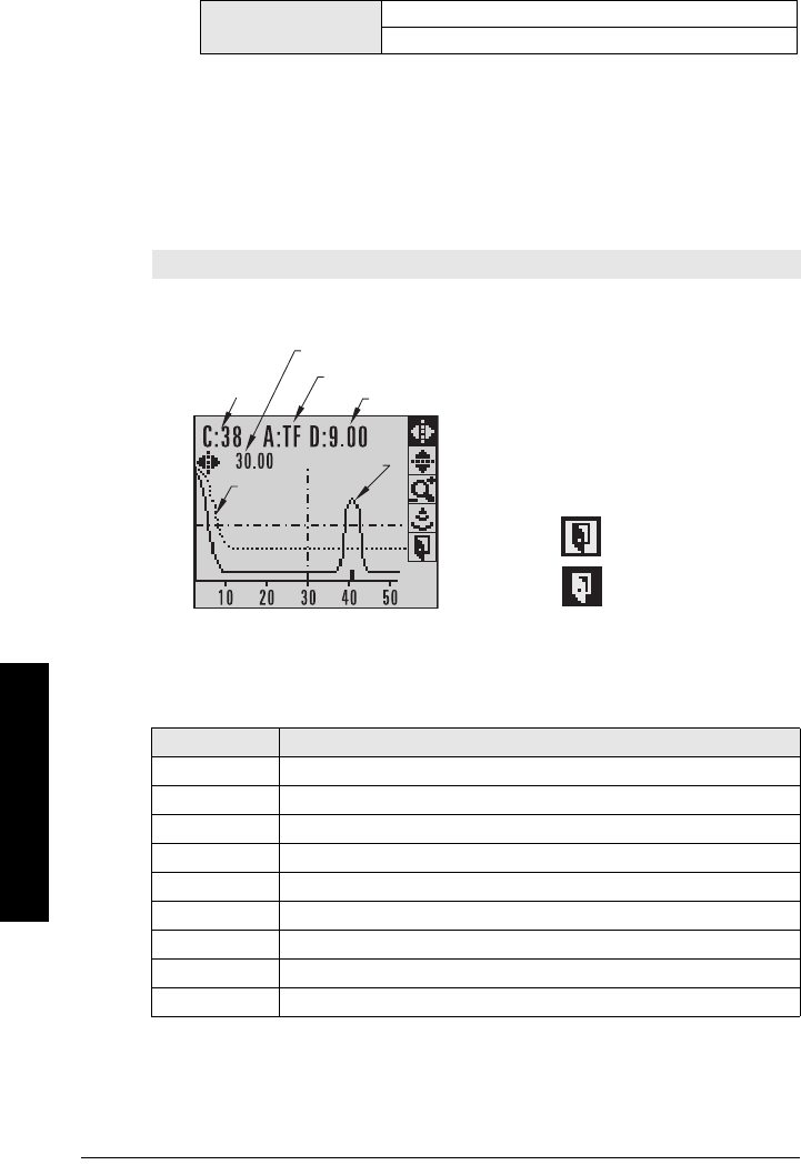
Page 82 SITRANS LR560 (PROFIBUS PA) – OPERATING INSTRUCTIONS 7ML19985LT01
mmmmm
Parameters
2.8.3. Average amount
The fraction of the old shot data that is kept for averaging purposes. A higher
value will give a smoother profile at the expense of a slower echo profile
response.
3. Diagnostics
3.1. Echo Profile
To request a profile via SIMATIC PDM:
Open the menu Device – Echo Profile Utilities. (See
Echo profile on page 46
for more
detail.)
To request a profile via the handheld programmer:
Navigate to Echo Profile (3.1.) and press RIGHT arrow. (See
Requesting an Echo
Profile on page 37
for more details.)
3.2. Fault Reset
Clears the following faults:
To clear a fault using the handheld programmer:
• Enter the fault code number then press RIGHT arrow.
Values 0.0 to 1.0
Default: 0.75
Note: Selected icon is highlighted.
Fault Code Description
S3 Device Lifetime Reminder 1 (Maintenance Required)
S4 Device Lifetime Reminder 2 (Maintenance Demanded)
S6 Sensor Lifetime Reminder 1 (Maintenance Required)
S7 Sensor Lifetime Reminder 2 (Maintenance Demanded)
S8 Device Service Reminder 1 (Maintenance Required)
S9 Device Service Reminder 2 (Maintenance Demanded)
S12 Internal Temperature High
S17 Calibration Schedule Reminder 1 (Maintenance Required)
S18 Calibration Schedule Reminder 2 (Maintenance Demanded)
measure
pan left/right - selected/highlighted
distance from flange face to target
algorithm selection (trueFirst echo)
TVT
curve
material
level
confidence
value
zoom in/out
exit
Echo Amplitude (dB)
pan up/down
distance from Low Calibration Point to vertical cross-hair
Measurement Range
(0 to 50 m for example purposes)
exit icon selected /
highlighted
exit icon,
deselected
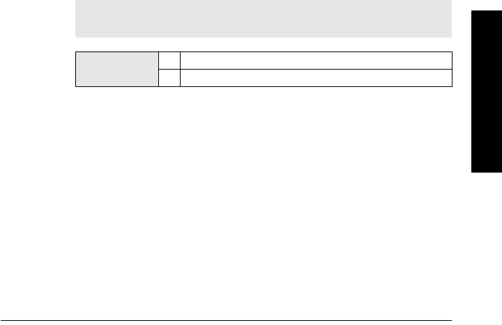
7ML19985LT01 SITRANS LR560 (PROFIBUS PA) – OPERATING INSTRUCTIONS Page 83
mmmmm
Parameters
To clear a fault via SIMATIC PDM:
• Open the menu Device – Acknowledge Faults.
• Select the fault to be cleared from the pull-down menu in Extended
Diagnostics.
• Click on Transfer to clear the fault.
3.3. Trend
Displays the trend of the Process Variables: sensor value, and outputs from AIFB1/
AIFB2. Samples are saved every minute up to 3200 samples.
To view via SIMATIC PDM:
Open the menu View – Process Variables and click on the tab Trend View.
3.4. Electronics Temperature
3.4.1. Minimum Value
The minimum recorded internal electronics temperature of the SITRANS LR560.
3.4.2. Maximum Value
The maximum recorded internal electronics temperature of the SITRANS
LR560.
3.4.3. Internal Temperature
The current internal electronics temperature of the device.
3.5. Condensed Status
When Enable (3.5.1.) is enabled, you can select the level of severity of errors, and
tailor a device response appropriate for your particular process.
•In Event Index (3.6.1.) you can select a particular event or error by means of its
index number.
•In Event Status (3.6.2.) you can assign a status to the selected event.
•In Event Diagnosis (3.6.3.) you can assign a diagnosis to the selected event.
3.5.1. Enable
Select Yes or No to enable/disable Condensed Mode.
3.5.2. Features supported
Read only. Features supported are:
• Condensed Diagnostics
• Extended Diagnostics
• Application Relationships
3.5.3. Features enabled
Read only. Lists those features that have been enabled.
Note: When cyclic communication is in progress, Condensed Status Mode
cannot be changed.
Options NO (disabled)
* YES (enabled)

Page 84 SITRANS LR560 (PROFIBUS PA) – OPERATING INSTRUCTIONS 7ML19985LT01
mmmmm
Parameters
3.6. Allocation
3.6.1. Event Index
The numeric component of the Event Code for a Condensed Status event. Use
the index number to identify a particular event in the list below.
For example:
Event Code for Loss of Echo = S0
Event Index = 0
To select a particular event via the handheld programmer:
a) Go to Enable (3.5.1.) and select Yes to enable Condensed Mode.
b) Go to Event Index (3.6.1.) and enter the event index number corresponding
to the event.
To select a particular event via SIMATIC PDM:
a) Go to Maintenance & Diagnostics > Condensed Status > Enable and
select Yes to enable Condensed Mode.
b) Go to Maintenance & Diagnostics > Allocation Level.
c) For each event, you can select either the Status or the Diagnosis line, then
choose a Status or Diagnosis option from the associated pull-down menu.
Event
Index
Event
Code Event Descriptiona)
a) See
General Fault Codes on page 108
for the meaning of each event.
0S0 Loss of Echo
2S2 No Tech Power
10 S10 Level Transducer Block (LTB) Scale
11 S11 Internal Temperature Sensor
12 S12 Internal Temperature High
14 S14 AIFB1 PV Range
15 S15 AIFB2 PV Range
25 S25 Internal error
28 S28 Memory RAM
29 S29 Memory EEPROM
30 S30 Memory EEPROM Flags
31 S31 Memory Flash
33 S33 Internal Temperature Calibration
34 S34 Velocity Calibration
35 S35 Receiver Init Calibration
36 S36 Receiver Calibration
37 S37 Technology Module Calibration
38 S38 Technology Module Ramp

7ML19985LT01 SITRANS LR560 (PROFIBUS PA) – OPERATING INSTRUCTIONS Page 85
mmmmm
Parameters
3.6.2. Event Status
Event Status allows you to assign one of the status options listed below, to any
of the events listed in Event Index (3.6.1.). This allows you to tailor a device
response appropriate for your particular process.
(Event Status affects
Condensed Status
1)
).
To assign a status to a particular event via the handheld programmer:
a) Go to Enable (3.5.1.) and select Yes to enable Condensed Mode.
b) Go to Event Index (3.6.1.) and enter the event index number corresponding
to a particular event.
c) Go to Event Status (3.6.2.) and choose a Status option from the table
above.
To assign a status to a particular event via SIMATIC PDM:
a) Go to Level Meter > Maintenance & Diagnostics > Condensed Status >
Enable and select Yes to enable Condensed Status Mode.
b) Go to Level Meter > Maintenance & Diagnostics > Allocation Level.
c) Select the Status line for the selected Event, then choose a Status option
from the associated pull-down menu.
3.6.3. Event Diagnosis
Allows you to assign one of the diagnostic options listed below to any of the
events listed in Event Index (3.6.1.). This allows you to tailor a device response
appropriate for your particular process.(Event Diagnosis affects Condensed
Acyclic Diagnostics and Cyclic Extended Diagnostics
2)
)..
Event Status Options
Good
Good: maintenance required
Good: maintenance demanded
Uncertain: maintenance demanded
* Bad: maintenance alarm
Uncertain: process related, no maintenance
Bad: process related, no maintenance
Bad: function check/local override
Good: function check
1) See
Condensed Status on page 132
for more detail.
Event Diagnosis Options
Status OK
Maintenance Required
Maintenance Demanded
* Maintenance alarm
Invalid process conditions
Function check or simulation
2) See
Condensed Mode Diagnosis on page 136
for more detail.

Page 86 SITRANS LR560 (PROFIBUS PA) – OPERATING INSTRUCTIONS 7ML19985LT01
mmmmm
Parameters
To assign a diagnosis to a particular event via the handheld programmer:
a) Go to Enable (3.5.1.) and select Yes to enable Condensed Mode.
b) Go to Event Index (3.6.1.) and enter the event index number corresponding
to a particular event.
c) Go to Event Diagnosis (3.6.3.) and choose a Diagnosis option from the table
above.
To assign a status to a particular event via SIMATIC PDM:
a) Go to Level Meter > Maintenance & Diagnostics > Condensed Status >
Enable, and select Yes to enable Condensed Status Mode.
b) Go to Level Meter > Maintenance & Diagnostics > Allocation Level.
c) Select the Diagnosis line for the selected Event, then choose a Diagnosis
option from the associated pull-down menu.
3.7. Peak Values
To view via SIMATIC PDM:
Open the menu View – Device Diagnostics, select Device Status, and click on the tab
Device Status. For more details see
Device Diagnostics on page 57
.
3.7.1. Min. Measured Value
The minimum recorded Sensor value, reported in units defined in Unit (2.3.1.).
3.7.2. Max. Measured Value
The maximum recorded Sensor value, reported in units defined in Unit (2.3.1.).
3.7.3. Minimum Output Value - AIFB1
The minimum recorded Output Value from the Analog Input Function Block 1.
3.7.4. Maximum Output Value - AIFB1
The maximum recorded Output Value from the Analog Input Function Block 1.
3.7.5. Minimum Output Value - AIFB2
The minimum recorded Output Value from the Analog Input Function Block 2.
3.7.6. Maximum Output Value - AIFB2
The maximum recorded Output Value from the Analog Input Function Block 2.
4. Service
4.1. Demo Mode
Reduces the time between measurements and the accuracy for demonstration
purposes.
Note: Default settings in the parameter tables are indicated with an asterisk (*)
unless explicitly stated.

7ML19985LT01 SITRANS LR560 (PROFIBUS PA) – OPERATING INSTRUCTIONS Page 87
mmmmm
Parameters
4.2. Master Reset
To access via SIMATIC PDM:
Open the menu Device – Master Reset. For more detail see
Master Reset on page 55
.
To perform a reset via the handheld programmer:
a) Press RIGHT Arrow to open Edit Mode then scroll down to the desired Reset
option and press RIGHT Arrow to select it.
b) Press LEFT Arrow to exit.
4.3. Powered Hours
Read only. Displays the number of hours the unit has been powered up since
manufacture.
To view via SIMATIC PDM, open the menu Device – Wear.
Notes:
• Following a reset, some degree of reprogramming may be required, depending
on the option chosen below.
• While performing any reset, a loss of communications can be expected.
Reset Options Result
Factory Defaults
Resets all user parameters to the manufacturer’s default settings,
with certain exceptions. The list of exceptions includes, but is not
limited to:
• Message
•Description
• Installation Data
• Device Address
•Write Protection
•Auto False Echo Suppression Range
• Learned TVT
•Language
Standard
Defaults
Resets all parameters, excluding device addresses and Language, to
the PROFIBUS standard default settings.
NOTE: After initiating a reset to Standard Defaults via the local
user interface, allow 1-2 minutes before initiating a new
command locally.
Informational Resets parameters such as Tag.
Functional Resets parameters that control device behavior and functionality
(such as calibration points)
Warm Start Has the same effect as recycling power to the device
Reset Address
to 126
• Resets the PROFIBUS device address to 126
• If the address lock was on, will disable the lock.

Page 88 SITRANS LR560 (PROFIBUS PA) – OPERATING INSTRUCTIONS 7ML19985LT01
mmmmm
Parameters
4.4. Power-on Resets
Read only. The number of power cycles that have occurred since manufacture.
To view via SIMATIC PDM, open the menu Device – Wear.
4.5. LCD Backlight
Time the backlight remains on.
4.6. LCD Contrast
The factory setting is for optimum visibility at room temperature and in average light
conditions. Extremes of temperature will lessen the contrast.
Adjust the value to improve visibility in different temperatures and light conditions.
Change the value in small steps to ensure you can continue to read the display.
To access LCD Contrast via SIMATIC PDM:
Navigate to Level Meter > Setup > Local Display.
4.7. Remaining Device Lifetime
The device tracks itself based on operating hours and monitors its predicted lifetime.
You can modify the expected device lifetime, set up schedules for maintenance
reminders, and acknowledge them.
The maintenance warnings and alarms are communicated via the Status byte. This
information can be integrated into any Asset Management system. For optimal use,
we recommend that you use SIMATIC PCS7 Asset Management Software in
conjunction with SIMATIC PDM.
Options Range: 0 (backlight off) to 128 seconds (backlight always on).
Default: 128 seconds
Values Range: 0 to 20
Default: 8
Contrast setting will depend on ambient
temperature.
Notes:
• Default settings in the parameter tables are indicated with an asterisk (*) unless
explicitly stated.
• Four sets of parameters allow you to monitor the Device/Sensor Lifetimes and
set up Service/Calibration schedules, based on operating hours instead of a
calendar-based schedule. See also Remaining Sensor Lifetime (4.8.), Service
Schedule (4.9.), and Calibration Schedule (4.10.).
• Performing a reset to Factory Defaults will reset all the Maintenance Schedule
parameters to their factory defaults.
• The device operates in years. To view Remaining Device Lifetime parameters in
hours or days (via SIMATIC PDM only) see Lifetime Expected (4.7.1.).
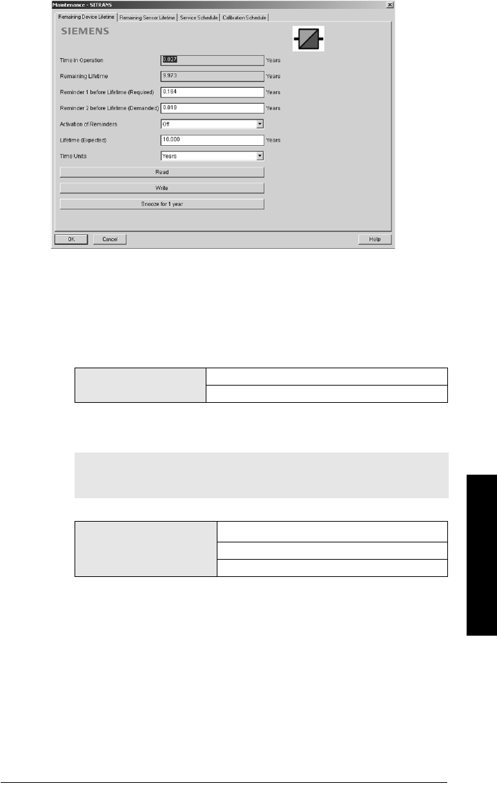
7ML19985LT01 SITRANS LR560 (PROFIBUS PA) – OPERATING INSTRUCTIONS Page 89
mmmmm
Parameters
To access these parameters via SIMATIC PDM:
• Open the menu Device – Maintenance and select the Remaining Device Lifetime
tab.
• After modifying values/units as required, click on Write to accept the change,
and Read to view the effect of the change.
• Click on Snooze to add a year to the Total Expected Device Life.
Time Units
4.7.1. Lifetime Expected
Allows you to override the factory default.
4.7.2. Time in Operation
Read only. The amount of time the device has been operating in years.
4.7.3. Remaining Lifetime
Read only. Lifetime Expected (4.7.1.) less Time in Operation (4.7.2.).
Optionsa)
a) Selectable only via SIMATIC PDM.
Hours; days; years
Default: years
Note: The device always operates in years. Changing the units affects only
the parameter view of the Remaining Device Lifetime parameters in
SIMATIC PDM.
Values
Unitsa): hours, days, years
a) Units are selectable only via SIMATIC PDM.
Range: 0 to 20 years
Default: 10.00 years

Page 90 SITRANS LR560 (PROFIBUS PA) – OPERATING INSTRUCTIONS 7ML19985LT01
mmmmm
Parameters
4.7.4. Reminder Activation
Allows you to enable a maintenance reminder.
a) First set the values in Reminder 1 (Required) (4.7.5.)/Reminder 2
(Demanded) (4.7.6.).
b) Select the desired Reminder Activation option.
4.7.5. Reminder 1 (Required)
If Remaining Lifetime (4.7.3.) is equal to or less than this value, the device
generates a Maintenance Required reminder.
a) Modify values as required.
b) Set Reminder Activation (4.7.4.) to the desired option.
4.7.6. Reminder 2 (Demanded)
If Remaining Lifetime (4.7.3.) is equal to or less than this value, the device
generates a Maintenance Demanded reminder.
a) Modify limit values as required.
b) Set Reminder Activation (4.7.4.) to the desired option.
4.7.7. Maintenance Status
Indicates which level of maintenance reminder is active.
In SIMATIC PDM, open the menu View – Device Diagnostics, select Device
Status, click on the Maintenance tab, and check the Device Lifetime Status
window.
4.7.8. Acknowledge Status
Indicates which level of maintenance reminder has been acknowledged.
In SIMATIC PDM, open the menu View – Device Diagnostics, select Device
Status, click on the Maintenance tab, and check the Device Lifetime Status
window.
Note: To modify this parameter via SIMATIC PDM it must be accessed via the
pull-down menu Device – Maintenance.
Values
REMinder 1 (Maintenance REQuired)
REMinder 2 (Maintenance DEManded)
REMinders 1 AND 2 (Maintenance Required and Maintenance
Demanded)
*OFF
Values Range: 0 to 20 years
Default: 0.164 years
Values Range: 0 to 20 years
Default: 0.019 years
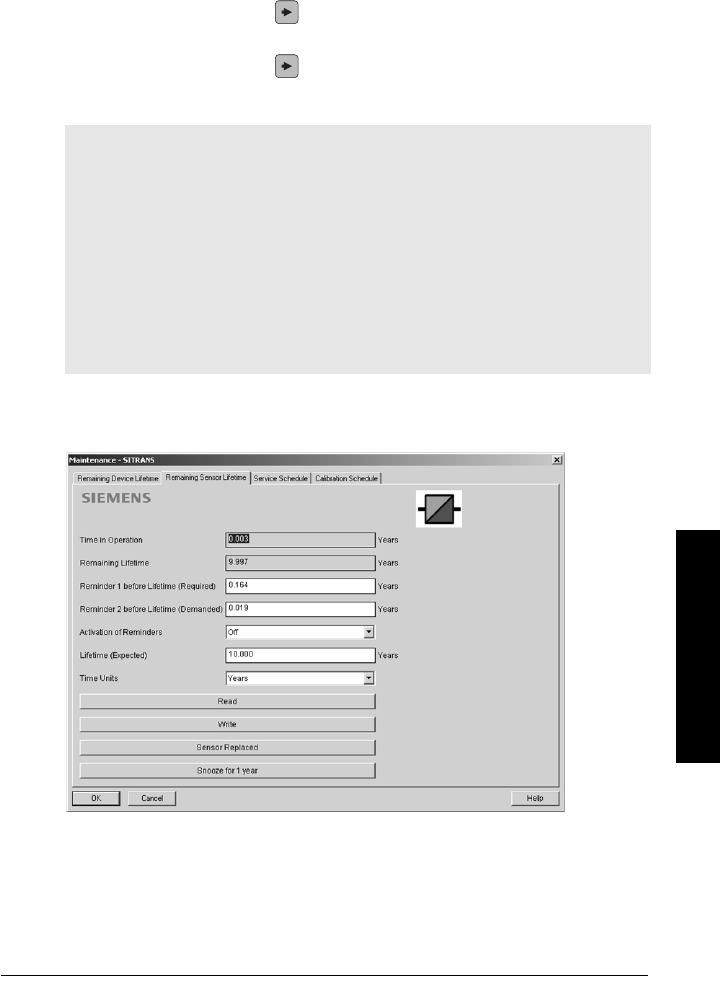
7ML19985LT01 SITRANS LR560 (PROFIBUS PA) – OPERATING INSTRUCTIONS Page 91
mmmmm
Parameters
4.7.9. Acknowledge
Acknowledges the current maintenance reminder.
To acknowledge a reminder via SIMATIC PDM:
a) Open the menu View – Device Diagnostics, select Device Status, and click
on the Maintenance tab.
b) In the Device Lifetime section, click on Acknowledge Warnings.
To acknowledge a reminder via the handheld programmer:
a) Press RIGHT arrow twice to open parameter view and activate Edit
Mode.
b) Press RIGHT arrow to acknowledge the reminder.
4.8. Remaining Sensor Lifetime
The device monitors the predicted lifetime of the sensor (the components exposed to
the vessel environment). You can modify the expected sensor lifetime, set up
schedules for maintenance reminders, and acknowledge them.
See
To access these parameters via SIMATIC PDM: on page 92
Notes:
• Default settings in the parameter tables are indicated with an asterisk (*) unless
explicitly stated.
• Four sets of parameters allow you to monitor the Device/Sensor Lifetimes and
set up Service/Calibration schedules, based on operating hours instead of a
calendar-based schedule. See also Remaining Device Lifetime (4.7.), Service
Schedule (4.9.), and Calibration Schedule (4.10.).
• Performing a reset to Factory Defaults will reset all the Maintenance Schedule
parameters to their factory defaults.
• The device operates in years. To view Remaining Sensor Lifetime parameters in
hours or days (via SIMATIC PDM only) see Lifetime Expected (4.8.1.).

Page 92 SITRANS LR560 (PROFIBUS PA) – OPERATING INSTRUCTIONS 7ML19985LT01
mmmmm
Parameters
To access these parameters via SIMATIC PDM:
• Open the menu Device – Maintenance and select the Remaining Sensor
Lifetime tab.
• After modifying values/units as required, click on Write to accept the change,
and Read to view the effect of the change.
• Click on Snooze to add a year to the Total Expected Sensor Life.
• Click on Sensor Replaced to restart the timer and clear any fault messages.
Time Units
4.8.1. Lifetime Expected
Allows you to override the factory default.
4.8.2. Time in Operation
The amount of time the sensor has been operating. Can be reset to zero after
performing a service or replacing the sensor.
To reset to zero:
• In SIMATIC PDM, open the menu Device – Maintenance, click on the
Remaining Sensor Lifetime tab, and click on Sensor Replaced to restart
the timer and clear any fault messages.
• Via the handheld programmer, manually reset Time in Operation (4.8.2.) to
zero.
4.8.3. Remaining Lifetime
Read only. Lifetime Expected (4.8.1.) less Time in Operation (4.8.2.).
Optionsa)
a) Selectable only via SIMATIC PDM.
Hours; days; years
Default: years
Note: The device always operates in years. Changing the units affects only
the parameter view of Remaining Sensor Life parameters in SIMATIC PDM.
Values
Unitsa): hours, days, years
a) Units are selectable only via SIMATIC PDM.
Range: 0 to 20 years
Default: 10.00 years

7ML19985LT01 SITRANS LR560 (PROFIBUS PA) – OPERATING INSTRUCTIONS Page 93
mmmmm
Parameters
4.8.4. Reminder Activation
Allows you to enable a maintenance reminder
.
a) First set the values in Reminder 1 (Required) (4.8.5.)/Reminder 2
(Demanded) (4.8.6.).
b) Select the desired Reminder Activation option.
4.8.5. Reminder 1 (Required)
If Remaining Lifetime (4.8.3.) is equal to or less than this value, the device
generates a Maintenance Required reminder.
a) Modify values as required.
b) Set Reminder Activation (4.8.4.) to the desired option.
4.8.6. Reminder 2 (Demanded)
If Remaining Lifetime (4.8.3.) is equal to or less than this value, the device
generates a Maintenance Demanded reminder.
a) Modify values as required
b) Set Reminder Activation (4.8.4.) to the desired option.
4.8.7. Maintenance Status
Indicates which level of maintenance reminder is active.
In SIMATIC PDM, open the menu View – Device Diagnostics, select Device
Status, click on the Maintenance tab, and check the Sensor Lifetime Status
window.
4.8.8. Acknowledge Status
Indicates which level of maintenance reminder has been acknowledged.
In SIMATIC PDM, open the menu View – Device Diagnostics, select Device
Status, click on the Maintenance tab, and check the Sensor Lifetime Status
window.
Note: To modify this parameter via SIMATIC PDM it must be accessed via the
pull-down menu Device – Maintenance.
Options
REMinder 1 (Maintenance REQuired)
REMinder 2 (Maintenance DEManded)
REMinders 1 AND 2 (Maintenance Required and Maintenance
Demanded)
*OFF
Values Range: 0 to 20 years
Default: 0.164 years
Values Range: 0 to 20 years
Default: 0.019 years

Page 94 SITRANS LR560 (PROFIBUS PA) – OPERATING INSTRUCTIONS 7ML19985LT01
mmmmm
Parameters
4.8.9. Acknowledge
Acknowledges the current maintenance reminder.
To acknowledge a reminder via SIMATIC PDM:
a) Open the menu View – Device Diagnostics, select Device Status, and click
on the Maintenance tab.
b) In the Sensor Lifetime section click on Acknowledge Warnings.
To acknowledge a reminder via the handheld programmer:
a) Press RIGHT arrow twice to open parameter view and activate Edit
Mode.
b) Press RIGHT arrow to acknowledge the reminder
4.9. Service Schedule
The device tracks service intervals based on operating hours and monitors the
predicted lifetime to the next service. You can modify the Total Service Interval, set
schedules for Maintenance Alerts, and acknowledge them.
The maintenance warnings and alarms are communicated via the Status byte. This
information can be integrated into any Asset Management system. For optimal use,
we recommend that you use SIMATIC PCS7 Asset Management Software in
conjunction with SIMATIC PDM.
To access these parameters via SIMATIC PDM:
• Open the menu Device – Maintenance and select the Service Schedule tab.
• After modifying values/units as required, click on Write to accept the change,
and Read to view the effect of the change.
• Click on Service Performed to restart the timer and clear any fault messages.
Notes:
• Four sets of parameters allow you to monitor the Device/Sensor Lifetimes and
set up Service/Calibration schedules, based on operating hours instead of a
calendar-based schedule. See also Remaining Device Lifetime (4.7.), Remaining
Sensor Lifetime (4.8.), and Calibration Schedule (4.10.).
• Performing a reset to Factory Defaults will reset all the Maintenance Schedule
parameters to their factory defaults.
• The device operates in years. To view Service Interval parameters in hours or
days (via SIMATIC PDM only) see Service Interval (4.9.1.).
7ML19985LT01 SITRANS LR560 (PROFIBUS PA) – OPERATING INSTRUCTIONS Page 95
mmmmm
Parameters
Time Units
4.9.1. Service Interval
User-configurable recommended time between product inspections.
4.9.2. Time since Last Service
Time elapsed since last service. Can be reset to zero after performing a service.
To reset to zero:
• In SIMATIC PDM, open the menu Device – Maintenance, click on the
Service Schedule tab, and click on Service Performed to restart the timer
and clear any fault messages.
• Via the handheld programmer, manually reset Time since Last Service
(4.9.2.) to zero.
4.9.3. Time until Next Service
Read only. Service Interval (4.9.1.) less Time since Last Service (4.9.2.).
Optionsa)
a) Selectable only via SIMATIC PDM.
Hours; days; years
Default: years
Note: The device always operates in years. Changing the units affects only
the parameter view of the Service Interval parameters in SIMATIC PDM.
Values
Unitsa): hours, days, years
a) Units are selectable only via SIMATIC PDM.
Range: 0 to 20 years
Default: 1.0 year

Page 96 SITRANS LR560 (PROFIBUS PA) – OPERATING INSTRUCTIONS 7ML19985LT01
mmmmm
Parameters
4.9.4. Reminder Activation
Allows you to enable a maintenance reminder.
a) First set the values in Reminder 1 (Required) (4.9.5.)/Reminder 2
(Demanded) (4.9.6.).
b) Select the desired Reminder Activation option.
4.9.5. Reminder 1 (Required)
If Time until Next Service (4.9.3.) is equal to or less than this value, the device
generates a Maintenance Required reminder.
a) Modify values as required.
b) Set Reminder Activation (4.9.4.) to the desired option.
4.9.6. Reminder 2 (Demanded)
If Time until Next Service (4.9.3.) is equal to or less than this value, the device
generates a Maintenance Demanded reminder.
a) Modify values as required.
b) Set Reminder Activation (4.9.4.) to the desired option.
4.9.7. Maintenance Status
Indicates which level of maintenance reminder is active.
Open the menu View – Device Diagnostics, select Device Status, click on the
Maintenance tab and check the Service Schedule Status window.
4.9.8. Acknowledge Status
Indicates which level of maintenance reminder has been acknowledged.
Open the menu View – Device Diagnostics, select Device Status, click on the
Maintenance tab and check the Service Schedule Status window.
Note: To modify this parameter via SIMATIC PDM it must be accessed via the
pull-down menu Device – Maintenance.
Values
*Timer OFF
ON NO LIMITS
ON REMinder 1 (Maintenance Required) checked
ON REMinders 1 - 2 checked
ON REMinder 2 (Maintenance Demanded) checked
Values Range: 0 to 20 years
Default: 0.164 years
Values Range: 0 to 20 years
Default: 0.019 years

7ML19985LT01 SITRANS LR560 (PROFIBUS PA) – OPERATING INSTRUCTIONS Page 97
mmmmm
Parameters
4.9.9. Acknowledge
Acknowledges the current maintenance reminder.
To acknowledge a reminder via SIMATIC PDM:
a) Open the menu Open the menu View – Device Diagnostics, select Device
Status, and click on the Maintenance tab.
b) In the Service Schedule Status section click on Acknowledge Warnings.
To acknowledge a reminder via the handheld programmer:
a) Press RIGHT arrow twice to open parameter view and activate Edit
Mode.
b) Press RIGHT arrow to acknowledge the reminder.
4.10. Calibration Schedule
The device tracks calibration intervals based on operating hours and monitors the
predicted lifetime to the next calibration. You can modify the Calibration Interval, set
schedules for maintenance reminders, and acknowledge them.
To access these parameters via SIMATIC PDM:
• Open the menu Device – Maintenance and select the Calibration Schedule tab.
• After modifying values/units as required, click on Write to accept the change,
and Read to view the effect of the change.
• Click on Calibration Performed to restart the timer and clear any fault
messages.
(continued on next page)
Notes:
• Default settings in the parameter tables are indicated with an asterisk (*) unless
explicitly stated.
• Four sets of parameters allow you to monitor the Device/Sensor Lifetimes and
set up Service/Calibration schedules, based on operating hours instead of a
calendar-based schedule. See also Remaining Device Lifetime (4.7.), Remaining
Sensor Lifetime (4.8.), and Service Schedule (4.9.).
• Performing a reset to Factory Defaults will reset all the Maintenance Schedule
parameters to their factory defaults.
• The device operates in years. To view Calibration Interval parameters in hours or
days (via SIMATIC PDM only) see Calibration Interval (4.10.1.).
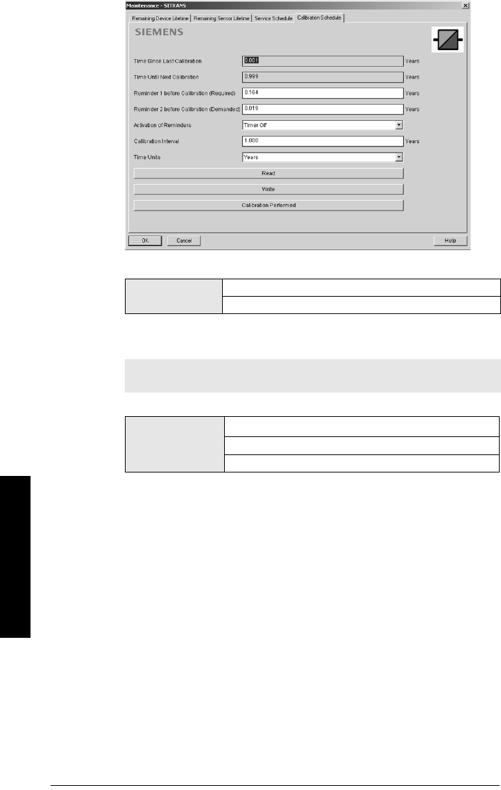
Page 98 SITRANS LR560 (PROFIBUS PA) – OPERATING INSTRUCTIONS 7ML19985LT01
mmmmm
Parameters
Time Units
4.10.1. Calibration Interval
User-configurable recommended time between product calibrations.
4.10.2. Time since Last Calibration
Time elapsed since last calibration. Can be reset to zero after performing a
calibration.
To reset to zero:
• In SIMATIC PDM, open the menu Device – Maintenance, click on the
Calibration Schedule tab, and click on Calibration Performed to restart the
timer and clear any fault messages.
• Via the handheld programmer, manually reset Time since Last Calibration
(4.10.2.) to zero.
4.10.3. Time until Next Calibration
Read only. Calibration Interval (4.10.1.) less Time since Last Calibration (4.10.2.)
Optionsa)
a) Selectable only via SIMATIC PDM.
Hours; days; years
Default: years
Note: The device always operates in years. Changing the units affects only
the parameter view of the Calibration Interval parameters in SIMATIC PDM.
Values
Unitsa): hours, days, years
a) Units are selectable only via SIMATIC PDM.
Range: 0 to 20 years
Default: 1.0 year

7ML19985LT01 SITRANS LR560 (PROFIBUS PA) – OPERATING INSTRUCTIONS Page 99
mmmmm
Parameters
4.10.4. Reminder Activation
Allows you to enable a maintenance reminder
.
a) First set the values in Reminder 1 (Required) (4.10.5.)/Reminder 2
(Demanded) (4.10.6.).
b) Select the desired Reminder Activation option.
4.10.5. Reminder 1 (Required)
If Time until Next Calibration (4.10.3.) is equal to or less than this value, the
device generates a Maintenance Required reminder.
a) Modify values as required.
b) Set Reminder Activation (4.10.4.) to the desired option.
4.10.6. Reminder 2 (Demanded)
If Time until Next Calibration (4.10.3.) is equal to or less than this value, the
device generates a Maintenance Demanded reminder.
a) Modify values as required.
b) Set Reminder Activation (4.10.4.) to the desired option.
4.10.7. Maintenance Status
Indicates which level of maintenance reminder is active.
In SIMATIC PDM, open the menu View – Device Diagnostics, select Device
Status, click on the Maintenance tab, and check the Calibration Schedule
Status window.
Note: To modify this parameter via SIMATIC PDM it must be accessed via the
pull-down menu Device – Maintenance.
Values
*Timer OFF
ON NO LIMITS
ON REMinder 1 (Maintenance Required) checked
ON REMinders 1 - 2 checked
ON REMinder 2 (Maintenance Demanded) checked
Values Range: 0 to 20 years
Default: 0.164 years
Values Range: 0 to 20 years
Default: 0.019 years

Page 100 SITRANS LR560 (PROFIBUS PA) – OPERATING INSTRUCTIONS 7ML19985LT01
mmmmm
Parameters
4.10.8. Acknowledge Status
Indicates which level of maintenance reminder has been acknowledged.
In SIMATIC PDM, open the menu View – Device Diagnostics, select Device
Status, click on the Maintenance tab, and check the Calibration Schedule
Status window.
4.10.9. Acknowledge
Acknowledges the current maintenance reminder.
To acknowledge a reminder via SIMATIC PDM:
a) Open the menu View – Device Diagnostics, select Device Status, and click
on the Maintenance tab.
b) In the Calibration Schedule Status section click on Acknowledge
Warnings.
To acknowledge a reminder via the handheld programmer:
a) Press RIGHT arrow twice to open parameter view and activate Edit
Mode.
b) Press RIGHT arrow to acknowledge the reminder.
5. Communication
5.1. Device Address
Sets the unique address of the device on the network (also called PROFIBUS
address).
To reset Device Address via SIMATIC PDM:
See
Set Address on page 40
.
To change Device Address via the handheld programmer:
See
Device Address on page 37
for details.
Note: Default settings in the parameter tables are indicated with an asterisk (*)
unless explicitly stated.
Note: The address can be changed and locked from a remote master. See
PROFI-
BUS address on page 130
for details on disabling the address lock and Master
Reset (4.2.) on page 87 to reset Device Address to 126.
Values 0 - 126. Default: 126

7ML19985LT01 SITRANS LR560 (PROFIBUS PA) – OPERATING INSTRUCTIONS Page 101
mmmmm
Parameters
5.2. PROFIBUS Ident Number
Identifies the device on the network. The Ident Number must match that in the GSD
file (the GSD file provides information on the device to the master).
6. Security
6.1. Remote Access
6.1.1. Remote Lockout
Enables or disables programming via the network and PDM.
6.2. Local Access
6.2.1. Write Protection
Prevents any changes to parameters via PDM or the hand-held programmer.
7. Language
Selects the language to be used on the LCD.
To access Language via SIMATIC PDM:
Navigate to Level Meter > Setup > Local Display.
Options
STD PROFILE Standard Profile (uses generic GSD for 2 AIFB
[ident # = 0x9701]
* MANUFACTURER
Manufacturer-specific (uses Siemens EDD and
GSD file, which identifies the LR560 [PROFIBUS
PA]) [ident # = 0x816B]
STD – AIFB 1 ONL. Standard Profile AIFB 1 only (uses generic GSD for
1 AIFB) [ident # = 0x9700]
Note: Default settings in the parameter tables are indicated with an asterisk (*)
unless explicitly stated.
Note: If access control is changed to limit remote access, it can be reset only
via the handheld programmer.
Options * OFF (Remote operation enabled)
ON (Remote operation disabled)
Hand-held
programmer
Values
Range: 0 to 9999
2457 (unlock value) Off (enables programming)
any other value On (disables programming)
Options
*ENGLISH
DEUTSCH
FRANÇAIS
ESPAÑOL
CHINESE

Page 102 SITRANS LR560 (PROFIBUS PA) – OPERATING INSTRUCTIONS 7ML19985LT01
mmmmm
Parameters
Notes

7ML19985LT01 SITRANS LR560(PROFIBUS PA) – OPERATING INSTRUCTIONS Page 103
mmmmm
A: Parameter List
Appendix A: Alphabetical Parameter
List
Parameter Name (Parameter Number) Page Number
AIFB1 (2.5.) 77
AIFB2 (2.6.) 81
Alarms and Warnings (2.5.7.) 79
Algorithm (2.4.5.1.) 71
Allocation (3.6.) 84
Auto False Echo Suppression (2.4.8.1.) 75
Auto False Echo Suppression Range (2.4.8.2.) 75
Average amount (2.8.3.) 82
Calibration (2.3.5.) 67
Calibration Schedule (4.10.) 97
Channel (2.5.3.) 77
CLEF Range (2.4.5.4.) 72
Condensed Status (3.5.) 83
Confidence (2.4.7.1.) 74
Decimal Point (2.5.8.4.) 80
Demo Mode (4.1.) 86
Descriptor (2.1.2.) 65
Device Address (5.1.) 100
Display (2.5.8.) 80
Echo Lock (2.4.6.1.) 73
Echo Profile (3.1.) 82
Echo Quality (2.4.7.) 74
Echo select (2.4.5.) 71
Echo Strength (2.4.7.2.) 74
Echo Threshold (2.4.5.3.) 72
Electronics Temperature (3.4.) 83
Empty rate/Min (2.3.6.3.) 69
Enable (3.5.1.) 83
Event Index (3.6.1.) 84
Event Status (3.6.2.) 85
Event Diagnosis (3.6.3.) 85
Far Range (2.4.2.) 70
Fault Reset (3.2.) 82
Features enabled (3.5.3.) 83
Features supported (3.5.2.) 83
Fill Rate/Min (2.3.6.2.) 69
Filter Time Constant (2.5.8.1.) 80

Page 104 SITRANS LR560 (PROFIBUS PA) – OPERATING INSTRUCTIONS 7ML19985LT01
mmmmm
A: Parameter List
Firmware Revision (2.2.2.) 65
Hardware Revision (2.2.1.) 65
High Calibration Pt. (2.3.5.2.) 67
High Limit Warning (2.5.7.2.) 79
High Limit Alarm (2.5.7.1.) 79
High Level Point (2.3.5.5.) 68
Hover Level (2.4.8.3.) 75
Identification (2.1.) 65
Input Scaling (2.5.5.) 78
Internal Temperature (3.4.3.) 83
Installation Date (2.1.4.) 65
Label (2.5.4.) 78
Language (7.) 101
LCD Backlight (4.5.) 88
LCD Contrast (4.6.) 88
Level Offset (2.3.5.6.) 68
Level Unit (2.3.2.) 66
Limit Hysteresis (2.5.7.5.) 79
Loader Revision (2.2.3.) 65
Local Access (6.2.) 101
LOE Timer (2.3.3.) 66
Low Calibration Pt. (2.3.5.1.) 67
Low Limit Warning (2.5.7.3.) 79
Low Limit Alarm (2.5.7.4.) 79
Low Level Point (2.3.5.4.) 68
Main Output (2.7.1.) 81
Manufacturing Date (2.2.5.) 66
Master Reset (4.2.) 87
Max. Measured Value (3.7.2.) 86
Maximum Output Value - AIFB1 (3.7.4.) 86
Maximum Output Value - AIFB2 (3.7.6.) 86
Maximum Sensor Value (2.4.4.) 70
Maximum Value (3.4.2.) 83
Measured Values (2.7.) 81
Menu timeout (2.2.4.) 66
Message (2.1.3.) 65
Min. Measured Value (3.7.1.) 86
Minimum Output Value - AIFB1 (3.7.3.) 86
Minimum Output Value - AIFB2 (3.7.5.) 86
Minimum Sensor Value (2.4.3.) 70
Minimum Value (3.4.1.) 83
Parameter Name (Parameter Number) Page Number

7ML19985LT01 SITRANS LR560(PROFIBUS PA) – OPERATING INSTRUCTIONS Page 105
mmmmm
A: Parameter List
Mode (2.5.2.) 77
Narrow Echo Filter (2.8.1.) 81
Near Range (2.4.1.) 69
Output, no level offset (2.7.3.) 81
Output, no linearization (2.7.2.) 81
Output Scaling (2.5.6.) 78
Out Unit Text (2.5.8.3.) 80
Peak Values (3.7.) 86
Position Detect (2.4.5.2.) 71
Powered Hours (4.3.) 87
Power-on Resets (4.4.) 88
PROFIBUS Ident Number (5.2.) 101
Quick Start (1.) 62
Rate (2.3.6.) 68
Reform Echo (2.8.2.) 81
Remaining Device Lifetime (4.7.) 88
Remaining Sensor Lifetime (4.8.) 91
Remote Access (6.1.) 101
Remote Lockout (6.1.1.) 101
Response Rate (2.3.6.1.) 68
Sampling (2.4.6.) 73
Sampling down (2.4.6.3.) 73
Sampling up (2.4.6.2.) 73
Sensor (2.3.) 66
Sensor Offset (2.3.5.3.) 68
Service Schedule (4.9.) 94
Shaper Mode (2.4.8.4.) 75
Signal Processing (2.4.) 69
Static Revision No. (2.5.1.) 77
Tag (2.1.1.) 65
Temperature Unit (2.3.4.) 67
Trend (3.3.) 83
TVT setup (2.4.8.) 75
TVT shaper (2.4.9.) 76
Unit (2.3.1.) 66
Value (2.5.9.2.) 81
Write Protection (6.2.1.) 101
Parameter Name (Parameter Number) Page Number

Page 106 SITRANS LR560 (PROFIBUS PA) – OPERATING INSTRUCTIONS 7ML19985LT01
mmmmm
B: Troubleshooting
Appendix B: Troubleshooting
Communication Troubleshooting
1. Check the following:
• There is power at the instrument.
• The LCD shows the relevant data.
• The device can be programmed using the hand-held programmer.
• If any fault codes are being displayed see
Acyclic Extended Diagnostics
(General Fault Codes)
on page 138 for a detailed list.
2. Verify that the wiring connections are correct.
3. Check the PROFIBUS address and make sure all devices are at unique PROFIBUS
addresses.
4. See the table below for specific symptoms (continued on next page).
If you continue to experience problems, go to our website at: www.siemens.com/LR560,
and check the FAQs for SITRANS LR560, or contact your Siemens Milltronics
representative.
Symptom Corrective action
The device cannot be
programmed via the hand-
held programmer.
•Make sure Write Protection (6.2.1.) on page 101 is set to the
unlock value.
You try to set a SITRANS
LR560 parameter via remote
communications but the
parameter remains
unchanged.
•Ensure Remote Lockout (6.1.1.) on page 101 is disabled.
•Ensure Write Protection (6.2.1.) on page 101 is set to the
unlock value.
• See
To reset the PROFIBUS address to 126:
on page
55 to disable an address lock.
The PLC value equals the
display value but does not
correspond to actual material
level.
•Ensure Scaling in AIFB1 is correctly entered.
• Ensure High Calibration Point is correctly entered.
• View the echo profile to see if the wrong echo is
being selected. If so, see
Operation Troubleshooting
on page 112 for possible causes and corrective
action.
The PLC value is not equal to
the displayed value
(regardless of actual material
level).
• Confirm you are looking at the right spot in the PLC.
• Ensure scaling has not been programmed into the
PLC: all scaling should be performed by the LR560.
• Check the network to ensure the PCL is communicat-
ing with the LR560.
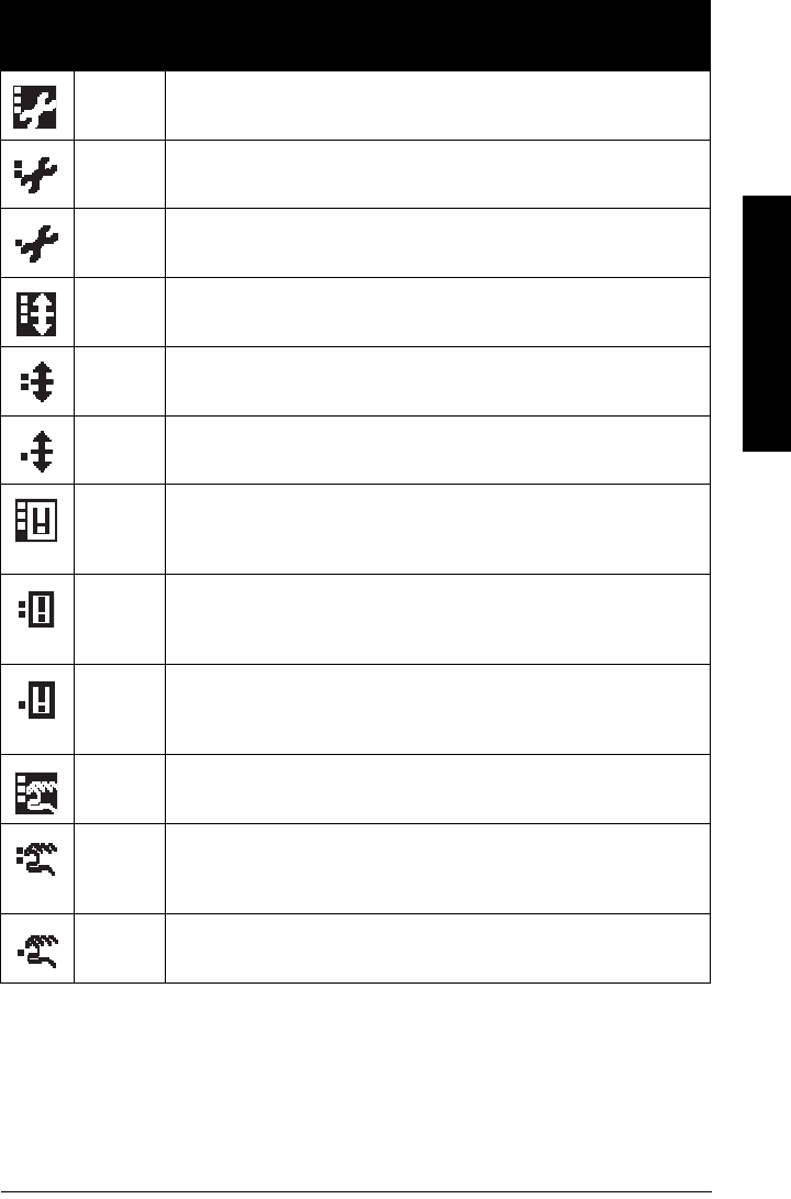
7ML19985LT01 SITRANS LR560 (PROFIBUS PA) – OPERATING INSTRUCTIONS Page 107
mmmmm
B: Troubleshooting
Device Status Icons
Icon Priority
Level Meaning
1 • Maintenance alarm
• Measurement values are not valid
2 • Maintenance warning: maintenance demanded immediately
• Measured signal still valid
3 • Maintenance required
• Measured signal still valid
1 • Process value has reached an alarm limit
2 • Process value has reached a warning limit
3 • Process value has reached a tolerance limit
1 • Configuration error
• Device will not work because one or more parameters/components
is incorrectly configured
2 • Configuration warning
• Device can work but one or more parameters/components is incor-
rectly configured
3 • Configuration changed
• Device parameterization not consistent with parameterization in
project. Look for info text.
1 • Manual operation (local override)
• Communication is good; device is in manual mode.
2 • Simulation or substitute value
• Communication is good; device is in simulation mode or works with
substitute values.
3 • Out of operation
• Communication is good; device is out of action.

Page 108 SITRANS LR560 (PROFIBUS PA) – OPERATING INSTRUCTIONS 7ML19985LT01
mmmmm
B: Troubleshooting
General Fault Codes
•Data exchanged
• No data exchange
• Write access enabled
• Write access disabled
Notes:
• The status icon shown associated with each fault is the default icon in Condensed Mode.
• If more than one fault is present, the device status indicator and text for each fault
alternate at 2 second intervals.
• Some faults cause the device to go to Fail-safe mode. These are indicated with an
asterisk (*).
General Fault Codes
Code /
Icon Meaning Corrective Action
S:0 * The device was unable to get a
measurement within the Fail-safe
LOE Timer period. Possible causes:
faulty installation, antenna material
buildup, foaming/other adverse
process conditions, invalid
calibration range.
• Ensure installation details are cor-
rect.
• Ensure no material buildup. Clean
if necessary.
• Adjust process conditions to mini-
mize foam or other adverse condi-
tions.
• Correct range calibration.
• If fault persists, contact your local
Siemens representative.
S: 2 * Unable to collect profile because of
a power condition that is outside the
operating range of the device.
Repair required. Contact your local
Siemens representative.
Icon Priority
Level Meaning (cont’d)

7ML19985LT01 SITRANS LR560 (PROFIBUS PA) – OPERATING INSTRUCTIONS Page 109
mmmmm
B: Troubleshooting
S: 3 Device is nearing its lifetime limit
according to the value set in
Reminder 1 (Required) (4.7.5.).
Replacement is recommended.
S: 4 Device is nearing its lifetime limit
according to the value set in
Reminder 2 (Demanded) (4.7.6.).
Replacement is recommended.
S: 6 Sensor is nearing its lifetime limit
according to the value set in
Reminder 1 (Required) (4.8.5.).
Replacement is recommended.
S: 7 Sensor is nearing its lifetime limit
according to the value set in
Reminder 2 (Demanded) (4.8.6.).
Replacement is recommended.
S: 8 Service interval as defined in
Reminder 1 (Required) (4.9.5.) has
expired.
Perform service.
S: 9 Service interval as defined in
Reminder 2 (Demanded) (4.9.6.) has
expired.
Perform service.
S:10
Input parameters Low Calibration Pt.
(2.3.5.1.) and High Calibration Pt.
(2.3.5.2.) are the same.
• Check calibration settings of
device.
• Ensure settings for High Calibra-
tion Point and Low Calibration
Point are different.
S: 11 Internal temperature sensor failure. Repair required: contact your local
Siemens representative.
General Fault Codes (cont’d)
Code /
Icon Meaning Corrective Action

Page 110 SITRANS LR560 (PROFIBUS PA) – OPERATING INSTRUCTIONS 7ML19985LT01
mmmmm
B: Troubleshooting
S: 12 Internal temperature of device has
exceeded specifications: it is
operating outside its temperature
range.
• Relocate device and/or lower pro-
cess temperature enough to cool
device.
• Inspect for heat-related damage
and contact your local Siemens
representative if repair is required.
• Fault code will persist until a man-
ual reset is performed using PDM
or the LCD interface.
S:14 Input Scaling (2.5.5.) Upper and
lower values for AIFB1 are the
same.
• Check configuration for AIFB1.
• Ensure that Upper Value and
Lower Value (Input Scaling) are
not the same.
S:15 Input Scaling (2.5.5.) Upper and
lower values for AIFB2 are the
same.
• Check configuration for AIFB2.
• Ensure that Upper Value and
Lower Value (Input Scaling) are
not the same.
S: 17 Calibration interval as defined in
Reminder 1 (Required) (4.10.5.) has
expired.
Perform calibration.
S: 18 Calibration interval as defined in
Reminder 2 (Demanded) (4.10.6.) has
expired.
Perform calibration.
S:25 Internal error. Reset power. If fault persists,
contact your local Siemens
representative.
S: 27 Internal device failure caused by an
External RAM memory error.
Repair required: contact your local
Siemens representative.
S: 28 * Internal device failure caused by a
RAM memory error.
Repair required: contact your local
Siemens representative.
General Fault Codes (cont’d)
Code /
Icon Meaning Corrective Action

7ML19985LT01 SITRANS LR560 (PROFIBUS PA) – OPERATING INSTRUCTIONS Page 111
mmmmm
B: Troubleshooting
S: 29 * EEPROM damaged. Repair required: contact your local
Siemens representative.
S: 30 EEPROM corrupt. Reset power. If fault persists,
contact your local Siemens
representative.
S: 31 * Flash error. Repair required: contact your local
Siemens representative.
S: 32 IDENT number conflict. Ensure value of the Ident number
selector is correct for the network
configuration. If it is correct, the
device needs to be re-parameterized
by the PLC.
S: 33 * Factory calibration for the internal
temperature sensor has been lost.
Repair required: contact your local
Siemens representative.
S: 34 * Factory calibration for the device
has been lost.
Repair required: contact your local
Siemens representative.
S:39 Transducer temperature sensor
failure.
Repair required: contact your local
Siemens representative.
S:40 Transducer temperature too high. Relocate device and/or lower
process temperature enough to cool
device. Inspect for heat-related
damage and contact your local
Siemens representative if repair is
required.
General Fault Codes (cont’d)
Code /
Icon Meaning Corrective Action

Page 112 SITRANS LR560 (PROFIBUS PA) – OPERATING INSTRUCTIONS 7ML19985LT01
mmmmm
B: Troubleshooting
Operation Troubleshooting
Operating symptoms, probable causes, and resolutions (continued on next page).
S: 41 Transducer temperature too low. Relocate device and/or raise
process temperature enough to
warm device. Inspect for
temperature-related damage and
contact your local Siemens
representative if repair is required.
S:64
to
S:83
Device error.
NOTE: Fault text and icons appear
only on LCD.
Repair required. Contact your local
Siemens representative.
S:94
to
S:108
Device error.
NOTE: Fault text and icons appear
only on LCD.
Repair required. Contact your local
Siemens representative.
Operation Troubleshooting
Symptom Cause Action
Display shows
S: 0 LOE
level or target is out of
range
• check specifications
•check Low Calibration Pt. (2.3.5.1.)
• increase Confidence (2.4.7.1.)
Display shows
S: 0 LOE
material build-up on
antenna
• Use the air purge feature to clean the
antenna
• re-locate SITRANS LR560
Display shows
S: 0 LOE
location or aiming:
• poor installation
• flange not level
• Auto False Echo Suppres-
sion may be incorrectly
applied
• check to ensure nozzle is vertical
• ensure end of antenna protrudes
from end of nozzle.
• review
Auto False Echo Suppression
(2.4.8.1.)
on page 118
• ensure Auto Suppression Range is
set correctly
General Fault Codes (cont’d)
Code /
Icon Meaning Corrective Action

7ML19985LT01 SITRANS LR560 (PROFIBUS PA) – OPERATING INSTRUCTIONS Page 113
mmmmm
B: Troubleshooting
Display shows
S: 0 LOE
antenna malfunction:
• temperature too high
• physical damage
• check temperature in Maximum
Value (3.4.2.)
•relocate
Reading does not
change, but the level
does
SITRANS LR560 processing
wrong echo, i.e. vessel
wall, or structural member
• re-locate SITRANS LR560
• check nozzle for internal burrs or
welds
• rotate instrument 90°
•use Auto False Echo Suppression
(2.4.8.1.) if necessary: see
Auto False
Echo Suppression (2.4.8.1.)
on page
118
Measurement is
consistently off by a
constant amount
• setting for Low Calibra-
tion Pt. not correct
• setting for Sensor Offset
not correct
• check distance from sensor refer-
ence point to Low Calibration Pt.
(2.3.5.1.)
•check Sensor Offset (2.3.5.3.)
Screen blank
power error • check nameplate rating against volt-
age supply
• check power wiring or source
Reading erratic echo confidence weak • refer to Confidence (2.4.7.1.)
•useAuto False Echo Suppression
(2.4.8.1.) and Auto False Echo Sup-
pression Range (2.4.8.2.)
material filling • re-locate SITRANS LR560
Reading response
slow
Fill Rate/Min (2.3.6.2.)
setting is incorrect
• increase measurement response if
possible
Reads correctly but
occasionally reads
high when vessel is
not full
• detecting close range
echo
• build up near top of ves-
sel or nozzle
• nozzle problem
• Use the air purge feature to clean the
antenna
•use Auto False Echo Suppression
(2.4.8.1.) and Auto False Echo Sup-
pression Range (2.4.8.2.)
Level reading lower
than material level
• material is within Near
Range zone
• multiple echoes pro-
cessed
• decrease Near Range (2.4.1.): mini-
mum value depends on antenna type
• raise SITRANS LR560
• ensure Algorithm (2.4.5.1.) is set to tF
(trueFirst echo)
Operation Troubleshooting (cont’d)
Symptom Cause Action

Page 114 SITRANS LR560 (PROFIBUS PA) – OPERATING INSTRUCTIONS 7ML19985LT01
mmmmm
C: Maintenance
Appendix C: Maintenance
SITRANS LR560 requires no maintenance or cleaning under normal operating conditions.
Under severe operating conditions, the antenna may require periodic cleaning. If
cleaning becomes necessary:
• Note the antenna material and the process medium, and select a cleaning
solution that will not react adversely with either.
• Remove the instrument from service and wipe the antenna clean using a cloth
and suitable cleaning solution.
Unit Repair and Excluded Liability
All changes and repairs must be done by qualified personnel, and applicable safety
regulations must be followed. Please note the following:
• The user is responsible for all changes and repairs made to the device.
• All new components must be provided by Siemens Milltronics Process Instruments
Inc.
• Restrict repair to faulty components only.
• Do not re-use faulty components.
• Contact your local Siemens representative for a list of spare part.

7ML19985LT01 SITRANS LR560 (PROFIBUS PA) – OPERATING INSTRUCTIONS Page 115
mmmmm
D: Technical Reference
Appendix D: Technical Reference
Principles of Operation
SITRANS LR560 is a 2-wire 78 GHz FMCW (Frequency Modulated Continuous Wave)
radar level transmitter for continuous monitoring of solids in vessels1). Radar level
measurement uses the time of flight principle to determine distance to a material surface.
FMCW radar transmits a continuous wave. The frequency of the wave is constantly
increasing: this is known as the sweep. By the time the first part of the wave has been
reflected off the target and returned to the device, the part of the wave that is just being
emitted is at a higher frequency. The difference in frequency between the transmitted and
received signals is proportional to time of flight.
Electromagnetic wave propagation is virtually unaffected by temperature or pressure
changes, or by changes in the vapor levels inside a vessel. Electromagnetic waves are
not attenuated by dust.
SITRANS LR560 consists of an enclosed electronic circuit coupled to an antenna and
process connection. The electronic circuit generates a radar signal (78 GHz) that is
directed to the lens antenna.
The signal is emitted from the lens antenna, and the reflected echoes are digitally
converted to an echo profile. The profile is analyzed to determine the distance from the
sensor reference point2) to the material surface. This value (sensor value) is used as a
basis for calculating the display of material level.
Process Variables
The Process Variables are sensor value and measured value. Sensor value is the
distance from the sensor reference point (flange face) to the material surface. The
measured value can be either Level (distance from low calibration point to material
surface), Distance (distance from sensor reference point to the material surface), or
Space (distance from high calibration point to the material surface).
Echo Processing
Process Intelligence
The signal processing technology embedded in Siemens radar level devices is known as
Process Intelligence.
Process intelligence provides high measurement reliability regardless of the dynamically
changing conditions within the vessel being monitored. The embedded Process
Intelligence dynamically adjusts to the constantly changing material surfaces within
these vessels.
Note: Where a number follows the parameter name (for example, Algorithm (2.4.5.1.)
this is the parameter access number via the local control buttons or the handheld
programmer. See
Parameter Reference
on page 62 for a complete list of parameters.
1) The microwave output level is significantly less than that emitted from cellular phones.
2) See
Dimensions
on page 12.
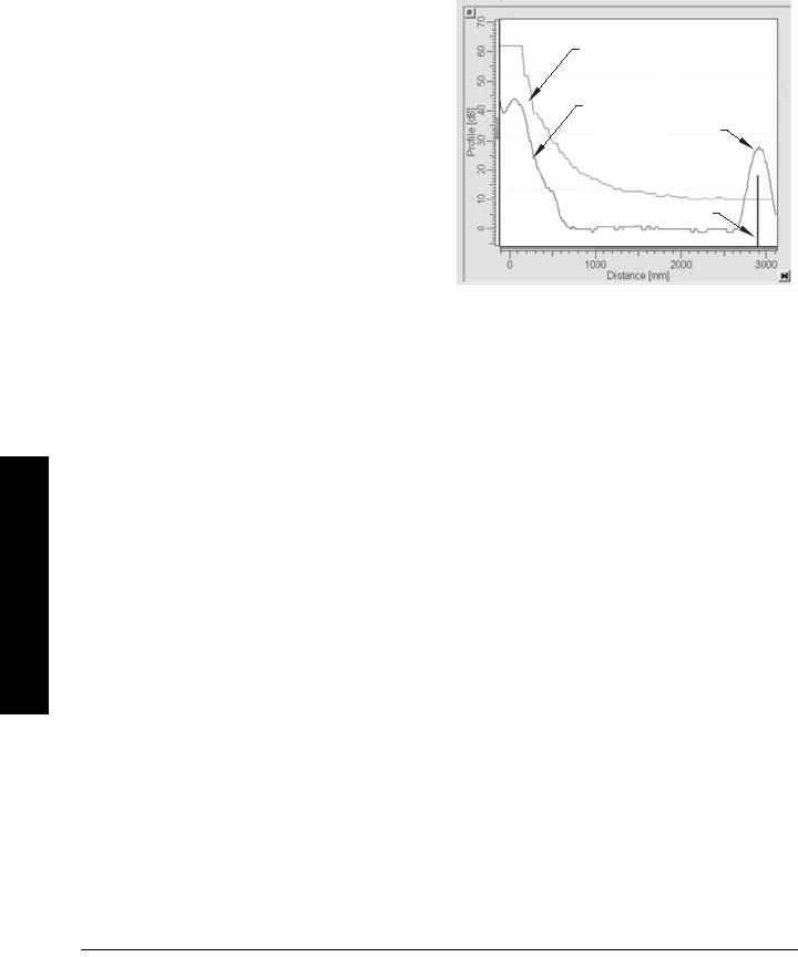
Page 116 SITRANS LR560 (PROFIBUS PA) – OPERATING INSTRUCTIONS 7ML19985LT01
mmmmm
D: Technical Reference
Process Intelligence is able to differentiate between the true microwave reflections from
the surface of the material and unwanted reflections being returned from obstructions
such as seam welds or supports within a vessel. The result is repeatable, fast and
reliable measurement. This technology was developed as result of field data gained over
some twenty years from more than 1,000,000 installations in many industries around the
world.
Higher order mathematical techniques and algorithms are used to provide intelligent
processing of microwave reflection profiles. This “knowledge based” technique
produces superior performance and reliability.
Echo Selection
Time Varying Threshold (TVT)
A Time Varying Threshold (TVT) hovers
above the echo profile to screen out
unwanted reflections (false echoes).
In most cases the material echo is the
only one which rises above the default
TVT.
In a vessel with obstructions, a false echo
may occur. See
Auto False Echo
Suppression (2.4.8.1.)
on page 118 for
more details.
The device characterizes all echoes that rise above the TVT as potential good echoes.
Each peak is assigned a rating based on its strength, area, height above the TVT, and
reliability, amongst other characteristics.
Algorithm (2.4.5.1.)
The true echo is selected based on the setting for the Echo selection algorithm. For a list
of options see Algorithm (2.4.5.1.) on page 71.
Position Detect (2.4.5.2.)
The echo position detection algorithm determines which point on the echo will be used to
calculate the precise time of flight, and calculates the range using the calibrated
propagation velocity. The following options are available:
• Rising
•Center
•Hybrid
•CLEF (Constrained Leading Edge Fit)
Rising
Uses rising edge of the echo.
Center
Uses center of the echo.
Hybrid
Uses the Center algorithm for the top part of the vessel, and the CLEF algorithm for the
part nearest the vessel bottom, according to the setting for CLEF range.
default TVT
material
level
echo marker
echo profile
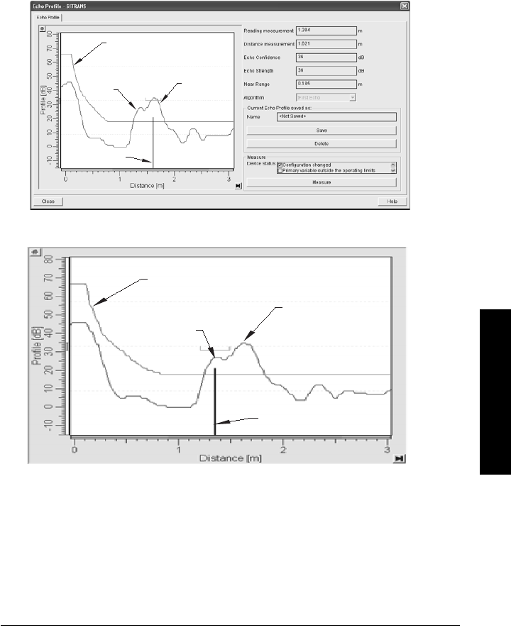
7ML19985LT01 SITRANS LR560 (PROFIBUS PA) – OPERATING INSTRUCTIONS Page 117
mmmmm
D: Technical Reference
CLEF (Constrained Leading Edge Fit)
• Uses the leading edge of the echo.
• Is used mainly to process the echo from materials with a low dK value.
In an almost empty flat-bottomed vessel, a low dK material may reflect an echo weaker
than the echo from the vessel bottom. The echo profile shows these echoes merging. The
device may then report a material level equal to or lower than empty
The CLEF algorithm enables the device to report the level correctly.
Example: CLEF off: Position set to Hybrid
Example: CLEF enabled
default TVT
vessel
bottom
echo
selected
material
echo
echo marker
Vessel height: 1.5 m; CLEF range set to 0 (Center algorithm gives the same result.)
default TVT
vessel
bottom
echo
material
echo
selected
echo marker
Vessel height: 1.5 m; CLEF range set to 0.5 m

Page 118 SITRANS LR560 (PROFIBUS PA) – OPERATING INSTRUCTIONS 7ML19985LT01
mmmmm
D: Technical Reference
CLEF Range (2.4.5.4.)
Determines the level below which the CLEF algorithm will be used. Above this level the
Center algorithm is used when Hybrid is selected in Position Detect (2.4.5.2.).
CLEF Range is referenced from Far Range.
Echo Threshold (2.4.5.3.)
Confidence (2.4.7.1.) describes the quality of an echo. Higher values represent higher
quality. Echo Threshold defines the minimum confidence value required for an echo to be
accepted as valid and evaluated.
Echo Lock (2.4.6.1.)
If the echo selected by Algorithm is within the Echo Lock window, the window is centered
about the echo, which is used to derive the measurement. In radar applications, two
measurement verification options are used:
Lock Off
SITRANS LR560 responds immediately to a new selected echo (within the restrictions set
by the Maximum Fill / Empty Rate), but measurement reliability is affected.
Material Agitator
A new measurement outside the Echo Lock Window must meet the sampling criteria
before the window will move to include it.
The other available options, Maximum Verification and Total Lock are not recommended
for radar.
Auto False Echo Suppression (2.4.8.1.)
Auto False Echo Suppression is designed to learn a specific environment (for example, a
particular vessel with known obstructions), and in conjunction with Auto False Echo
Suppression Range to remove false echoes appearing in front of the material echo.
Notes:
• For detailed instructions on using this feature via PDM see
Auto False Echo
Suppression
on page 48.
• For detailed instructions on using this feature via the handheld programmer see
Auto False Echo Suppression (2.4.8.1.) on page 75.
sensor
reference
point
CLEF Range Low Calibration
Point
Far
Range
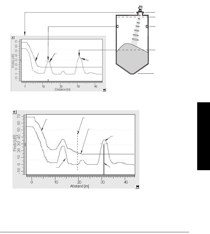
7ML19985LT01 SITRANS LR560 (PROFIBUS PA) – OPERATING INSTRUCTIONS Page 119
mmmmm
D: Technical Reference
The material level should be below all known obstructions at the moment when Auto
False Echo Suppression learns the echo profile. Ideally the vessel should be empty or
almost empty, and if an agitator is present, it should be running.
The device learns the echo profile over the whole measurement range and the TVT is
shaped around all echoes present at that moment.
Auto False Echo Suppression Range (2.4.8.2.)
Auto False Echo Suppression Range specifies the range within which the learned TVT is
applied. Default TVT is applied over the remainder of the range.
The learned TVT screens out the false echoes caused by obstructions. The default TVT
allows the material echo to rise above it.
Auto False Echo Suppression Range must be set to a distance shorter than the distance
to the material level when the environment was learned, to avoid the material echo being
screened out.
High Cal. Pt.
= 1 m
obstruction
at 13 m
material
level at 31 m
false
echo material
echo
default
TVT
sensor
reference
point
Example before Auto False Echo Suppression
Low Cal. Pt.
= 45 m
Example after Auto False Echo Suppression
learned
TVT
material
echo
false echo echo
marker
Auto False Echo
Suppression
Range set to 20 m
Auto False Echo
Suppression Range
default TVT
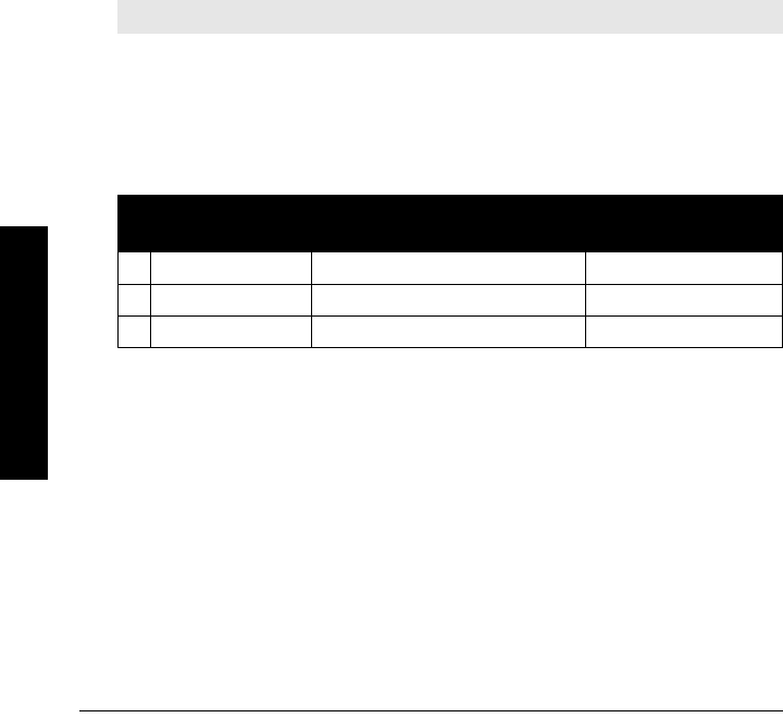
Page 120 SITRANS LR560 (PROFIBUS PA) – OPERATING INSTRUCTIONS 7ML19985LT01
mmmmm
D: Technical Reference
Measurement Range
Near Range (2.4.1.)
Near Range programs SITRANS LR560 to ignore the zone in front of the antenna. The
default blanking distance is 27.8 cm (0.91 ft) from the sensor reference point.
Near Range allows you to increase the blanking value from its factory default. But Auto
False Echo Suppression (2.4.8.1.) is generally recommended in preference to extending
the blanking distance from factory values.
Far Range (2.4.2.)
Far Range allows the echo processing to see and process signals that are lower than the
Low Calibration setting.
Potential uses are:
• In applications where the base of the vessel is conical or parabolic. A reliable echo
may be available below the vessel empty distance, due to an indirect reflection
path. Increasing Far Range to 30% or 40% can provide stable empty vessel readings.
• Where Low Calibration setting is above vessel empty level, but the vessel is emptied
occasionally. In this case the echo will be tracked below the Low Calibration setting
and the device will maintain a zero level reading.
Measurement Response
Response Rate (2.3.6.1.) limits the maximum rate at which the display and output respond
to changes in the measurement. There are three preset options: slow, medium, and fast.
Once the real process fill/empty rate (m/min by default) is established, a response rate
can be selected that is slightly higher than the application rate. Response Rate
automatically adjusts the filters that affect the output response rate
Note: Units are defined in Unit (2.3.1.) and are in meters by default.
Response Rate
(2.3.6.1.)
Fill Rate/Min (2.3.6.2.)/Empty
rate/Min (2.3.6.3.)
Filter Time Constant
(2.5.8.1.)
Slow 0.1 m/min (0.32 ft/min) 10 s
*Medium 1.0 m/min (3.28 ft/min) 10 s
Fast 10.0 m/min (32.8 ft/min) 0 s

7ML19985LT01 SITRANS LR560 (PROFIBUS PA) – OPERATING INSTRUCTIONS Page 121
mmmmm
D: Technical Reference
Damping
Filter Time Constant (2.5.8.1.) smooths out the response to a sudden change in level. This
is an exponential filter and the engineering unit is always in seconds.
In 5 time constants the output rises exponentially: from 63.2% of the change in the first
time constant, to almost 100% of the change by the end of the 5th time constant.
Loss of Echo (LOE)
A loss of echo (LOE) occurs when the calculated measurement is judged to be unreliable
because the echo confidence value has dropped below the echo confidence threshold.
Confidence (2.4.7.1.) describes the quality of an echo. HIgher values represent higher
quality.
Echo Threshold (2.4.5.3.)defines the minimum confidence value required for an echo to be
accepted as valid and evaluated.
If the LOE condition persists beyond the time limit set in LOE Timer (2.3.3.) the LCD
displays the Service Required icon, and the text region displays the fault code S: 0 and the
text LOE.
If two faults are present at the same time, the fault code, error text, and error icon for
each fault are displayed alternately. For example, Loss of Echo and faulty power supply:
S: 0 LOE S: 2 NO TECH POWER
Upon receiving a reliable echo, the loss of echo condition is aborted, the Service
Required icon and error message are cleared, and the reading returns to the current
level.
LOE Timer
LOE Timer (2.3.3.) determines the length of time a Loss of Echo (LOE) condition will persist
before a Fail-safe state is activated. The default is 100 seconds. Fail-safe Mode
determines the level to be reported when the Fail-safe timer expires.
Level (m)
Time (s)
smoothed output
input (level)
Damping example
time constant = 2 seconds
input (level) change = 2 m

Page 122 SITRANS LR560 (PROFIBUS PA) – OPERATING INSTRUCTIONS 7ML19985LT01
mmmmm
D: Technical Reference
Fail-safe Behavior
The purpose of the Fail-safe setting is to put the process into a safe mode of operation in
the event of a fault or failure. The value to be reported in the event of a fault is selected so
that a loss of power or loss of signal triggers the same response as an unsafe level.
Fail-safe mode may be triggered by a loss of echo, a bad configuration, or certain device
faults. You can select one of three possible values to be reported when a Fail-safe mode
is activated.
Mode (2.5.9.1.)
Mode determines the material level to be reported when LOE Timer (2.3.3.) expires.
Value (2.5.9.2.)
Value defines the material level to be reported if the option Use substitute value is
selected in Mode (2.5.9.1.).
The two Analog Input Function blocks are set separately.
To set a user-defined value
• Navigate to the Level Meter > Setup > desired Analog Input (1 or 2).
•Set Mode (2.5.9.1.) to Use substitute value.
•Go to Value (2.5.9.2.) and enter the desired value.
Mode (2.5.9.1.)
SUB VALUE Use substitute value. Value (2.5.9.2.) used as output value.
LAST VALUE * Last value (Store last valid output value).
USE BAD VALUE Use bad value (Calculated output value is incorrect).
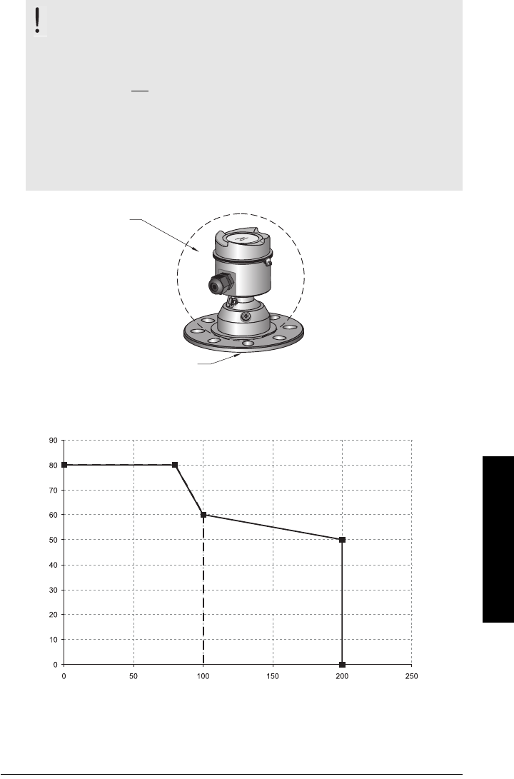
7ML19985LT01 SITRANS LR560 (PROFIBUS PA) – OPERATING INSTRUCTIONS Page 123
mmmmm
D: Technical Reference
Temperature derating curve
Temperature De-Rating
WARNINGS:
• Never attempt to loosen, remove or disassemble process connection
or instrument housing while vessel contents are under pressure.
• This product is not intended for use as a safety device per Directive 97/23/EC.
• The user is responsible for the selection of bolting and gasket
materials which will fall within the limits of the flange and its intended
use and which are suitable for the service conditions.
• Improper installation may result in loss of process pressure and/or
release of process fluids and/or gases.
ambient temperature
–40 °C to 80 °C
(–40 °F to 176 °F)
process temperature:
–40 to +100 °C (–40 to +212 °F) or
–40 to +200 °C (–40 to +392 °F) depending on the version
Process Temperature (°C)
Ambient Temperature (°C)
high temperature
version
standard
version
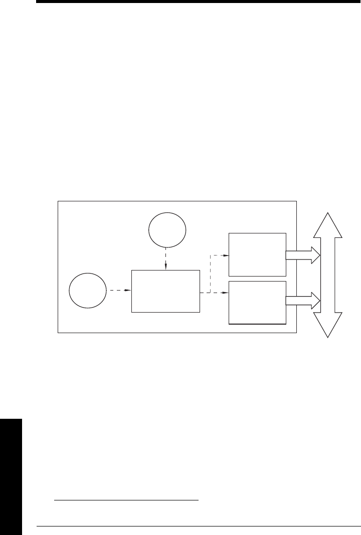
Page 124 SITRANS LR560 (PROFIBUS PA) – OPERATING INSTRUCTIONS 7ML19985LT01
mmmmm
E: Profile structure
Appendix E: PROFIBUS PA Profile
Structure
PROFIBUS Level Device Design
The device follows the profile block model and is implemented as a Profile 3.01, Class B,
PA device. Standard profile parameters are used to program the level transducer block.
Block Model
The Block Model represents how measured values are recorded and processed. All data
is viewed from the perspective of the DCS or PLC, so information from the sensor is an
input.
The functions of the device are divided into blocks with different areas of responsibility.
The blocks are configured by parameters.
The device is implemented with one Physical Block, one Transducer Block (TB), and two
Analog Input Function Blocks (AIFB1 and AIFB2).
Physical Block
The Physical Block handles functionality and descriptions relating to the device as a
whole: for example, LCD Contrast (functionality) and Firmware Revision and Tag
(descriptions).
Transducer Block (TB)
The Transducer Block carries out adjustments to the sensor, such as level calibration (and
volume calibration, if supported). It supplies the measured value1) utilized by either or
both of the AIFBs.
Analog Input Function Blocks AIFB1 and AIFB2
The two AIFBs are identical and completely independent of each other. They utilize the
measured value1) output from the Transducer Block and apply any required quality
checks, scaling, and Fail-safe operation selections.
The output from the Analog Input Function Block supplies the measured value with
associated status information to the PROFIBUS PA network via cyclic data transfer.
1) Primary Value (PV), Secondary Value 1 (SV1), or Secondary Value 2 (SV2)
sensor
sensor
Transducer Block
electronics
temperature
Analog Input
Function Block2
Analog Input
Function Block1
PROFIBUS PA
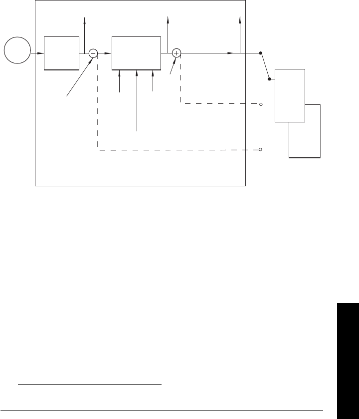
7ML19985LT01 SITRANS LR560 (PROFIBUS PA) – OPERATING INSTRUCTIONS Page 125
mmmmm
E: Profile structure
Description of the blocks
Transducer Block
The figure below shows the signal flow of measured values from the sensor through the
Transducer Block into the output value:
•Primary Value (PV)
1): Level (or Volume, if supported. LR560 does not support
volume).
• Secondary Value 1 (SV1): Level
• Secondary Value 2 (SV2): Distance
The Transducer Block implements all of the basic parameters of the PROFIBUS profile
standard (illustrated in step 2 below).
How the Transducer Block works:
1) The sensor technology sub-block selects the proper echo. For an explanation of
sensor technology, see
Appendix D: Technical Reference
, page 115 onwards.
The sensor value (in sensor units) is checked to see if it is within its measuring limits.
If the limit is exceeded, this results in a Bad status and the error message Failure in
measurement. The sensor value is stored in Sensor Value.
The analog signal from the sensor is transformed into a digital representation.
A Sensor Offset (default 0) compensates for changes to the sensor reference point,
if necessary.
(continued on next page)
1) PV output is provided for PROFIBUS Profile for Process Devices 3.01 compatibility.
Transducer Block
Sensor Value
Sensor Sensor
technology Level
calibration (no
Linearization)
Level Primary Value
[Level/Volume]
(volume not
supported)
level units
(Analog
Input)
AIFB1
Secondary Value 1
[Level]
(Level Units)
Secondary Value 2
[Distance]
(Sensor Units)
Sensor
Offset
Level
Offset
High
Calibration
Point
High Level
Point
Low
Calibration
Point
Low Level
Point
Calibration
Type
PV
SV1
SV2
AIFB2
(Analog
Input)
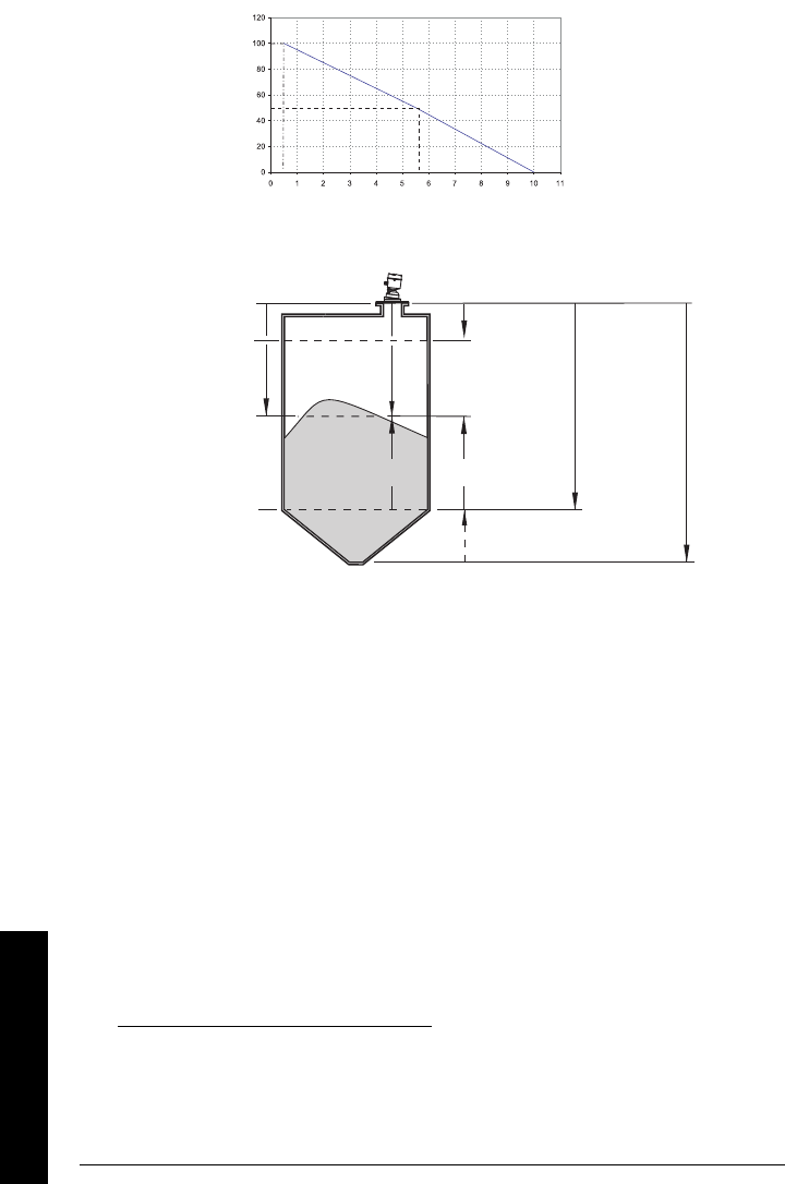
Page 126 SITRANS LR560 (PROFIBUS PA) – OPERATING INSTRUCTIONS 7ML19985LT01
mmmmm
E: Profile structure
2) Level Calibration is a linear transfer function that converts a sensor value to a level
value. 1)2)
3) The Transducer Block provides three possible outputs
• Primary Value (PV): Level (level units)3)
• Secondary Value 1 (SV1): Level (level units)
• Secondary Value 2 (SV2): Distance (sensor units)
1) Sensor Offset (2.3.5.3.) is a constant offset (negative or positive) that can be added to
sensor value to compensate if the sensor has been changed.
2) Level Offset (default O) can compensate for specific vessel configurations.
3) LR560 PA does not support Volume.
Level
High Level Point
Low Level Point Calibration
Level Value
Low
Calibration
Point
HIgh
Calibration
Point
Sensor
Value
High Level Point
(default: 100%)
sensor
reference
point
(flange
face)
sensor
value1)
Low Level Point
(default: 0%)
Level/PV
Level Offset2)
(if used)
Level /SV1
Low
Calibration
Point
High
Calibration
Point
Distance/SV2
SITRANS LR560
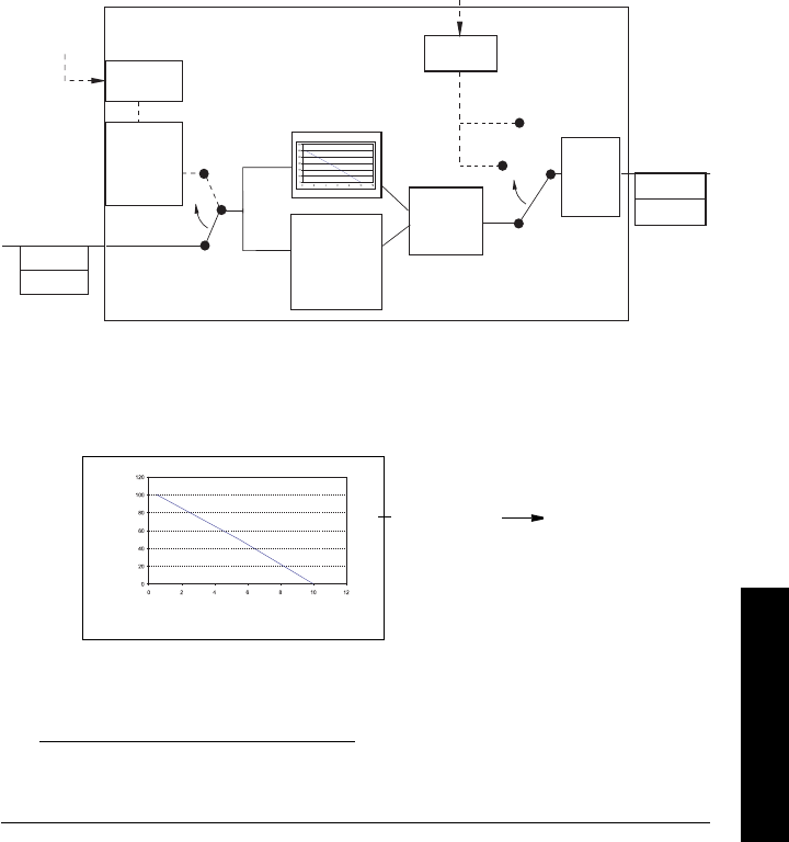
7ML19985LT01 SITRANS LR560 (PROFIBUS PA) – OPERATING INSTRUCTIONS Page 127
mmmmm
E: Profile structure
Electronics temperature
The Transducer Block monitors the internal temperature of the device electronics. A
change in temperature can provide advance warning of a possible device failure, and
allow for preventive maintenance.
If a temperature limit is exceeded, the output value is unchanged but the output status
changes. (The permitted limits correspond to those of the permitted ambient
temperature.)
Peak indicators1) allow you to check the maximum and minimum temperatures that have
occurred.
AIFB (simulation, mode and status)
The input to the AIFB is a value with a status. The figure below shows how Measured
values are processed within an Analog Input Function Block to produce the device output
(communicated via cyclic transfer to PROFIBUS PA and displayed on the LCD).
How an Analog Input Function Block works
The AIFB provides a linear conversion to any desired units.
1) The value input to the AIFB is the measured value output from the Transducer Block,
in sensor units.
2) You can select any standard engineering units, or define a special unit, for the AIFB
output. Then scaling is applied.
(continued on next page)
1) Open the menu View – Device Diagnostics, select Device Status, and click on the tab
Device Status to see peak temperature values.
enable
Status
OUT
VALUE
AUTO
MODE
and
STATUS
handling
AIFB INPUT:
measured
value from
TB
Value
Status
Alarm
Limit
Check
Out of Service
OUT
MANUAL
Value
simulate
value and
status
Value
Status
USER-
selected
Simulation
USER-selected Target Mode
OFF
SIMULATION
Fail-
safe
ON
OUTPUT
SCALING
Analog Input Function Block
AIFB
AIFB Input range
(typical Input (0 to 100%)
Output range:
Out
(AIFB Output) straight to LCD
(same values
displayed on LCD as
PLC)

Page 128 SITRANS LR560 (PROFIBUS PA) – OPERATING INSTRUCTIONS 7ML19985LT01
mmmmm
E: Profile structure
3) Damping may be applied based on a user-selected time constant (see
Damping
on
page 121 for details).
4) The status of the input value received from the Transducer Block is checked. If the
status is Bad, a Fail-safe condition occurs. The setting for Fail-safe Mode
determines the Fail-safe value to be output.
5) Mode (2.5.2.) allows the entire AI block to be overridden by a Manual Output value.
See
Simulate Output
on page 53 for details.
6) The value is checked against the user-defined warning and alarm limits. The upper and
lower limits are defined in units corresponding to the Output range, and a limit
hysteresis can be used to adjust the sensitivity. See Alarms and Warnings (2.5.7.) on
page 79 for the specific parameters.
7) The output value (OUT) is communicated via cyclic data transfer.

7ML19985LT01 SITRANS LR560 (PROFIBUS PA) – OPERATING INSTRUCTIONS Page 129
mmmmm
F: Communications PA
Appendix F: Communications via
PROFIBUS PA
SITRANS LR560 (PROFIBUS PA) is a Profile Version 3.01, Class B, PA device. It supports
Class 1 Master for cyclic and acyclic data exchange, and Class 2 for acyclic services.
The full range of SITRANS LR560 functions is available only over a PROFIBUS PA
network.
PROFIBUS PA is an open industrial protocol. Full details about PROFIBUS PA can be
obtained from PROFIBUS International at www.profibus.com.
Device Configuration tool
To use PROFIBUS PA, you will need a PC configuration tool: we recommend
SIMATIC PDM. Please consult the operating instructions or online help for details on
using SIMATIC PDM. (You can find more information at www.fielddevices.com: go to
Products and Solutions > Products and Systems > Communications and Software >
Process Device Manager.)
SIMATIC PDM
SIMATIC PDM is a software package used to commission and maintain SITRANS LR560
and other process devices. For more detail see
Functions in SIMATIC PDM
on page 39.
Electronic Device Description
In order to use Process Device Manager (PDM) with PROFIBUS PA, you will need the
Electronic Device Description for SITRANS LR560. For details see
Electronic Device
Description (EDD)
on page 39.
Network Configuration
To configure a PROFIBUS PA Class 1 Master (for example, a PLC), you will need a GSD
file.
The GSD file
The GSD file SIEM816B.gsd is available from the SITRANS LR560 product page on our
web site at www.siemens.com/LR560. Go to Support > Software Downloads.
Bus Termination
Power Demands
To determine how many devices can be connected to a bus line, calculate the combined
maximum current consumption of all the connected devices: 13.5 mA for SITRANS LR560.
Allow a current reserve for safety.
Note: PROFIBUS PA MUST be terminated at both extreme ends of the cable for it to
work properly. Please refer to the PROFIBUS PA User and Installation Guidelines (order
number 2.092), available from www.profibus.com.

Page 130 SITRANS LR560 (PROFIBUS PA) – OPERATING INSTRUCTIONS 7ML19985LT01
mmmmm
F: Communications PA
PROFIBUS address
A unique PROFIBUS address identifies each device on the network. To set the PROFIBUS
address see Device Address (5.1.) on page 100.
Resetting the PROFIBUS address to 126
• Via SIMATIC PDM:
a) Open the menu Device – Master Reset and click on Reset Address to 126.
b) Click on OK: the address will be reset to 126, and if the address lock was on, it
will be disabled.
• Via the handheld programmer:
a) Navigate to Service (4.) > Master Reset (4.2.). (You can enter the numeric value
instead of navigating via the Arrow keys.)
b) Press RIGHT Arrow to open Edit Mode then scroll down to DEV ADDRESS and
press RIGHT Arrow to select it. The address will be reset to 126, and if the
address lock was on, it will be disabled.
c) Press LEFT Arrow to exit.
Operating as a Profile Device
Every manufactured PROFIBUS product has a unique PROFIBUS identification number
which identifies it to the system. PROFIBUS Profile Standard version 3.01 also defines a
Profile Model which can identify a product as a generic profile device on the network.
SITRANS LR560 can be identified in one of three ways:
Defining the device as Profile-specific as opposed to Manufacturer-specific makes it
possible to exchange the device for any other device of the same profile type without
changing the GSD file.
To set up SITRANS LR560 as a profile device see PROFIBUS Ident Number (5.2.) on
page 101.
Notes:
• It is possible to change the device address via a Class 1 master (for example, a PLC)
and lock the device address to prevent further changes.
• If this Address Lock is on, the PA address cannot be changed. This lock can be
disabled only by performing an Address Reset.
Device Identification Profile Model
STD PROFILE Standard Profile (uses generic GSD for 2 AIFB [ident # =
0x9701]
* MANUFACTURER Manufacturer-specific (uses Siemens EDD and GSD file,
which identifies the LR560 [PROFIBUS PA]) [ident # = 0x816B]
STD – AIFB 1 ONLY Standard Profile AIFB 1 only (uses generic GSD for 1 AIFB)
[ident # = 0x9700]

7ML19985LT01 SITRANS LR560 (PROFIBUS PA) – OPERATING INSTRUCTIONS Page 131
mmmmm
F: Communications PA
Configuring a device
See
Configuring a new device
on page 40.
Configuring PROFIBUS PA with an S7-300/ 400 PLC
1) If SITRANS LR560 is not listed in the STEP 7 device catalog, you can download the
GSD file from the Siemens Web site and import it into Step 7. Go to
www.siemens.com/LR560 and click Downloads.
2) Add the SITRANS LR560 "rack": click and drag the SITRANS LR560 folder from the
hardware catalog.
3) Fill the rack with desired modules, by dragging and dropping them from the
hardware catalog.
4) After configuring PROFIBUS PA in steps 2 and 3, download it to the PLC.
5) Add code to the PLC program to read data consistently using the SFC14.
Cyclic versus Acyclic Data
When you request data from a device via PROFIBUS PA, you have two choices. Cyclic
data is provided at every bus scan: acyclic data is requested and provided as needed.
Input information is always requested at every bus scan and is set up as cyclic data.
Configuration information is only needed periodically and is set up as acyclic data.
Cyclic Data
When you configure SITRANS LR560 on the PROFIBUS PA bus, there are two slots
available for modules.
Slot 0 always transmits AIFB1 information1); slot 1 defaults to Free Place, but can be
changed to AIFB2 information. If you do not wish to have data transmitted, then you must
use a Free Place module in that slot.
Each of the two Analog Input Function Blocks can be set up to return Level, or Distance.
Within the function blocks, the values are scaled according to the user requirements
(please see
AIFB (simulation, mode and status)
on page 127 for details).
(continued on next page)
Note: Each of the slots has to have a module defined in it.
1) For more information, please see
AIFB (simulation, mode and status)
on page
127.

Page 132 SITRANS LR560 (PROFIBUS PA) – OPERATING INSTRUCTIONS 7ML19985LT01
mmmmm
F: Communications PA
AIFB1 and AIFB2 return 5 bytes of data each:
The first 4 bytes are the floating point representation (IEEE) of the variable. The variables
are the outputs of the function block. The 5th byte is the status word and the list of
possible values is given in the chart below.
The 5 bytes must be read consistently, in a contiguous chunk: they cannot be read byte by
byte, and cannot suffer an interrupt. If you are using an S7-300 / 400, you will need to use
SFC14 DPRD_DAT: Read Consistent Data of a Standard PD Slave.
Status Byte
In PROFIBUS PA there are two possible types of status byte:
•condensed status: one of two status bytes defined in Profile Standard V3.01
•status byte: the status byte originally defined in Profile Standard V3.0
You can choose which type of status byte will be returned, by enabling or disabling
Condensed Status (3.5.)
Condensed Status
These codes are available when Condensed Status is enabled. See Condensed Status
(3.5.) on page 83 for more details.
Condensed Status (GOOD)
Hex
value Status – GOOD Description
0x80 GOOD – ok No error or special condition is associated with this value.
0x84 GOOD – update event Set if the value is good and the block has an active Update
event. (This status remains active for 20 seconds.)
0x86 GOOD – active advi-
sory alarm Set if the value is good and the block has an active Alarm.
0x80
...0x8E
GOOD – limit check/
update event See
Status Codes for Good Quality
on page 134.
0xA0
...0xA3
GOOD – initiate fail
safe
This fault is not generated by the product, but can be simu-
lated.
Floating Point Status
AIFB2
AIFB1 byte 1 byte 2 byte 3 byte 4 byte 5
byte 6 byte 7 byte 8 byte 9 byte10byte10

7ML19985LT01 SITRANS LR560 (PROFIBUS PA) – OPERATING INSTRUCTIONS Page 133
mmmmm
F: Communications PA
0xA4
...0xA7
GOOD – maintenance
required
Value is valid. Maintenance is recommended within a
medium-term period.
0xA8
...0xAB
GOOD – maintenance
demanded
Value is valid. Maintenance is demanded within a short-
term period.
0xBC
...0xBF
GOOD – function
check
Device performs internal function check without influenc-
ing the process. Value is valid.
Condensed Status (UNCERTAIN)
Hex
value
Status –
UNCERTAIN Description
0x45 UNCERTAIN – substi-
tute set
Output of Failsafe logic only.
0x4F UNCERTAIN – initial
value
Default value as long as no measured value is available or
until a diagnosis is made that affects the value and the
status accorded to it.
0x68
...0x6B
UNCERTAIN – mainte-
nance demanded
Usability of the process value depends on the application.
Value is potentially invalid. Cause can be determined by
reading the extended diagnosticsa). Maintenance is
demanded within a short-term period.
0x73 UNCERTAIN – simu-
lated value, start
Indicates the start of a simulation.
Simulation of a measured value or Input FB mode changes
from AUTO to MAN.
• This status remains active for at least 10 seconds:
– after enabling simulation
– after setting the FB to MAN mode
– after a restart (e.g. power down cycle) if the simula-
tion is enabled or the FB is in MAN mode
– after passivation is cleared if simulation is enabled or
the FB is in MAN mode
• In MAN mode the status remains until a subsequent
write command overwrites the OUT value after the 10
seconds have expired.
• In simulation mode the written status is buffered and
appears in the value flow after 10 seconds. However the
new written SIMULATE parameter with its status can
be read before the 10 seconds have expired.
Condensed Status (GOOD) (cont’d)
Hex
value Status – GOOD Description

Page 134 SITRANS LR560 (PROFIBUS PA) – OPERATING INSTRUCTIONS 7ML19985LT01
mmmmm
F: Communications PA
Status Byte
When Condensed Status is disabled, Status Byte will be returned, and the following
codes will be used.
0x74
...0x77
UNCERTAIN – simu-
lated value, end
Indicates the end of a simulation.
Simulation of a measured value is disabled or Input FB
mode changes from MAN to AUTO.
This Status remains active for 10 seconds after simulation
ends.
While this status is active there is no reliable process
value. Measured values and their status are updated
afterwards.
a) See
Acyclic Extended Diagnostics (General Fault Codes)
on page 138.
Condensed Status (BAD)
Hex
value Status BAD Description
0x00 BAD – non specific Proxy determines that a device does not
communicate.
0x23 BAD – passivated (diagnostics alerts
disabled)
Configured failsafe value is used, accom-
panied by this status.
0x24
...0x27
BAD – maintenance alarm, more
diagnosis available
No measurement available because of a
failure.
0x25 BAD – process related, no mainte-
nance
No measurement available because of
invalid process conditions.
0x3C
...0x3F
BAD – function check / local over-
ride, value not usable
Occurs during cleaning or calibration pro-
cess.
Status Codes for Good Quality
Values in hex notation Description
0x80 Data is GOOD.
0x84 A parameter in the function block has been changed: status active
for 10 s
0x89 Active low warning.
0x8A Active high warning.
0x8D Active low alarm.
0x8E Active high alarm.
Condensed Status (UNCERTAIN) (cont’d)
Hex
value
Status –
UNCERTAIN Description

7ML19985LT01 SITRANS LR560 (PROFIBUS PA) – OPERATING INSTRUCTIONS Page 135
mmmmm
F: Communications PA
Diagnostics
All diagnostic information shown below is viewable via PDM.
Diagnosis reply (available cyclically)
During DPV0 data exchange, the PROFIBUS PA slave will notify the Master when a
serious error occurs. The Master will then send a Diagnosis request. The reply to this
request is normally logged in the PLC and is referred to as the "Hex values."
The reply may contain two parts. The first part is 6 bytes long and is defined by the
PROFIBUS standard. If there is a second part, it is called the ’extended cyclic diagnosis’
and it is 8 bytes long. The last 4 bytes of the extended diagnostic message give the error
diagnosis (see
Extended Mode Diagnosis
on page 137 and
Condensed Mode Diagnosis
on page 136).
The same information is also available acyclically via the Diagnosis Object.
Status Codes for Uncertain Quality
Values in hex notation Description
0x4B Value is a substituted value (normally used in Failsafe).
0x4C/0x4F Initial value.
0x47 Last usable value.
Status Codes for Bad Quality
Values in hex notation Description
0x10 The LOE timer has expired: this could be caused by LOE or by a sen-
sor malfunction: value is BAD.
0x01 There is an error in the configuration of the function blocks in PROFI-
BUS PAa).
a) This could happen when a firmware download has been done, but a system reset has not
been done. This could also happen if the function blocks are not configured properly using
the handheld programmer, PDM or acyclic services.
0X1F The function block, or the transducer block, has been placed out of
service.
Cyclic Diagnosis (6 bytes) Extended Cyclic Diagnosis (8 bytes)
Diagnosis Object
(last 4 bytes)
Condensed Mode
Diagnosis Extended Mode
Diagnosis

Page 136 SITRANS LR560 (PROFIBUS PA) – OPERATING INSTRUCTIONS 7ML19985LT01
mmmmm
F: Communications PA
Diagnosis Object (available cyclically or acyclically)
This consists of four bytes.
In PROFIBUS PA there are two options for the Diagnosis Object:
• Condensed Mode Diagnosis (see page 136)
• Extended Mode Diagnosis (see page 137)
You can choose which of these will be returned, by enabling or disabling Condensed
Status. See Enable (3.5.1.) on page 83.
Condensed Mode Diagnosis
Condensed Mode Diagnosis
Hex values Byte Bit Description Indication
classa)
a) R indicates the message remains active as long as the reason for the message exists.
A indicates the message will automatically reset after 10 seconds
0x01000000
0
0 Electronics failure R
0x02000000 1 Mechanical failure R
0x04000000 2 Motor Temperature too high R
0x08000000 3 Electronics temperature too high R
0x10000000 4 Memory error R
0x20000000 0 (cont’d) 5Measurement failure R
0x40000000 6 Device not initialized (no calibration) R
0x80000000 7 Self calibration failed R
0x00080000
2
3New startup carried out (Warm Start) A
0x00100000 4Restart carried out (Cold Start) A
0x00200000 5Maintenance required R
0x00400000 6Reserved for use within the PNO
0x00800000 7
Set to 1 (one), if the Ident_Number of the
running cyclic data transfer and the value of
Physical Block IDENT__NUMBER_SELECTOR
parameter are different.
R
0x00010000
3
0 Failure of the device or armature R
0x00020000 1 Maintenance demanded R
0x00040000 2 Device is in function check mode, or simulation,
or under local control e.g. maintenance R
0x00080000 3
The process conditions do not allow the return
of valid values. (Set if a value has the quality
Uncertain - Process related, no maintenance or
Bad - Process related, no maintenance.)
R
4 to 7 Reserved for use within the PNO
4
0 to 6 Reserved for use within the PNO
0x80000000 7
0: There is no more information available
1: More diagnosis information is available in
DIAGNOSIS_EXTENSION

7ML19985LT01 SITRANS LR560 (PROFIBUS PA) – OPERATING INSTRUCTIONS Page 137
mmmmm
F: Communications PA
Extended Mode Diagnosis
When Condensed Status is disabled Extended Mode Diagnosis will be returned, and the
following codes will be used.
Values of the DIAGNOSIS bit: 0 = not set; 1 = set
Extended Mode Diagnosis
Hex values Byte Bit Description Indication
classa)
a) R indicates the message remains active as long as the reason for the message exists.
A indicates the message will automatically reset after 10 seconds
0x01000000
0
0 Electronics failure R
0x02000000 1 Mechanical failure R
0x04000000 2 Motor Temperature too high R
0x08000000 3 Electronics temperature too high R
0x10000000 4 Memory error R
0x20000000 5 Measurement failure R
0x40000000 6 Device not initialized (no calibration) R
0x80000000 7 Self calibration failed R
0x00010000
1
0Zero point error (limit position) R
0x00020000 1Power supply failure (electrical, pneumatic) R
0x00040000 2Configuration invalid R
0x00080000 3New startup carried out (Warm Start) A
0x00100000 4Restart carried out (Cold Start) A
0x00200000 5Maintenance required R
0x00400000 6Characterization invalid R
0x00800000 7
Set to 1 (one), if the Ident_Number of the running
cyclic data transfer and the value of Physical Block
IDENT__NUMBER_SELECTOR parameter are
different.
R
2 0 to 7 Reserved for use within the PNO
30 to 6 Reserved for use within the PNO
0x00000080 7More diagnosis information is available

Page 138 SITRANS LR560 (PROFIBUS PA) – OPERATING INSTRUCTIONS 7ML19985LT01
mmmmm
F: Communications PA
Acyclic Extended Diagnostics (General Fault Codes)
In addition to the extended diagnostics available by cyclic data exchange (shown above),
further extended diagnostics are available via acyclic communications. This consists of
six bytes. See
Diagnosis reply (available cyclically)
on page 135 for information on the
location of the Extended Diagnostics
Note: Certain fault codes (identified by an asterisk [*] in the table below) will persist
until a manual reset has been performed (see Fault Reset (3.2.) on page 82).
Acyclic Extended Diagnostics /General Fault Codes
LCD
display Meaning Corrective Action Byte Bit
S:0
The device was unable to get a
measurement within the Fail-
safe LOE Timer period. Possible
causes: faulty installation,
antenna material buildup,
foaming/other adverse process
conditions, invalid calibration
range.
• Ensure installation details are
correct.
• Ensure no antenna material
buildup. Clean if necessary.
• Adjust process conditions to
minimize foam or other
adverse conditions.
• Correct range calibration.
• If fault persists, contact your
local Siemens representative.
0
0
S:2
Unable to collect profile
because of a power condition
that is outside the operating
range of the device.
Repair required. Contact your
local Siemens representative. 2
S:3
Device is nearing its lifetime
limit according to the value set
in Maintenance Required Limit.
Replacement is recommended.
3
S:4
Device is nearing its lifetime
limit according to the value set
in Maintenance Demanded
Limit.
Replacement is recommended.
4
S:6
Sensor is nearing its lifetime
limit according to the value set
in Maintenance Required Limit.
Replacement is recommended.
6
S:7
Sensor is nearing its lifetime
limit according to the value set
in Maintenance Demanded
Limit.
Replacement is recommended.
7

7ML19985LT01 SITRANS LR560 (PROFIBUS PA) – OPERATING INSTRUCTIONS Page 139
mmmmm
F: Communications PA
S:8
Service interval as defined in
Maintenance Required Limit
has expired.
Perform service.
1
0
S:9
Service interval as defined in
Maintenance Demanded Limit
has expired.
Perform service.
1
S:10
Input parameters High
Calibration Point and Low
Calibration Point are the same.
• Check calibration settings of
device.
• Ensure settings for High Cali-
bration Point and Low Calibra-
tion Point are different.
3
S:11 Internal temperature sensor
failure.
Repair required. Contact your
local Siemens representative. 4
S:12 *
Internal temperature of the
device has exceeded
specifications: it is operating
outside its temperature range.
• Relocate device and/or lower
process temperature enough
to cool device.
• Inspect for heat-related dam-
age and contact your local Sie-
mens representative if repair is
required.
• Fault code will persist until a
manual reset is performed
using PDM or the LCD inter-
face.
5
S:14
Upper and lower input values
(Process Value Scale) for AIFB1
are the same.
• Check configuration for AIFB1.
• Ensure that Upper Value and
Lower Value (Process Value
Scale) are not the same.
6
S:15
Upper and lower input values
(Process Value Scale) for AIFB2
are the same.
• Check configuration for AIFB2.
• Ensure that Upper Value and
Lower Value (Process Value
Scale) are not the same.
7
S: 17
Calibration interval as defined in
Maintenance Required Limit
has expired.
Perform calibration.
2
1
S: 18
Calibration interval as defined in
Maintenance Demanded Limit
has expired.
Perform calibration. 2
Acyclic Extended Diagnostics /General Fault Codes (cont’d)
LCD
display Meaning (cont’d) Corrective Action Byte
(cont’d) Bit

Page 140 SITRANS LR560 (PROFIBUS PA) – OPERATING INSTRUCTIONS 7ML19985LT01
mmmmm
F: Communications PA
S:25
Internal error. Reset power. If fault persists,
contact your local Siemens
representative.
3
1
S: 27 Internal device failure caused by
an External RAM memory error.
Repair required: contact your
local Siemens representative. 3
S:28 Internal device failure caused
by a RAM memory error.
Repair required: contact your
local Siemens representative. 4
S:29 EEPROM damaged. Repair required: contact your
local Siemens representative. 5
S: 30
EEPROM corrupt. Reset power. If fault persists,
contact your local Siemens
representative.
6
S:31 Flash error. Repair required: contact your
local Siemens representative. 7
S: 32 IDENT number conflict.
Ensure value of the Ident
number selector is correct for
the network configuration. If it is
correct, the device needs to be
re-parameterized by the PLC.
4
0
S:33
Factory calibration for the
internal temperature sensor
has been lost.
Repair required: contact your
local Siemens representative. 1
S:34 Factory calibration for the
device has been lost.
Repair required: contact your
local Siemens representative. 2
S:39 Transducer temperature sensor
failure.
Repair required: contact your
local Siemens representative. 7
S:40
Transducer temperature too
high.
Relocate device and/or lower
process temperature enough to
cool device. Inspect for heat-
related damage and contact your
local Siemens representative if
repair is required.
5 0
Acyclic Extended Diagnostics /General Fault Codes (cont’d)
LCD
display Meaning (cont’d) Corrective Action Byte
(cont’d) Bit

7ML19985LT01 SITRANS LR560 (PROFIBUS PA) – OPERATING INSTRUCTIONS Page 141
mmmmm
F: Communications PA
Acyclic Data
SITRANS LR560 supports up to four simultaneous connections by a Class 2 Master
(C2 connection). It supports one connection by a Class 1 Master (C1 connection).
In order for a Class 1 Master to read parameters from an instrument, it needs to know the
slot and absolute index of the parameter. You can download an application guide
’Reading acyclic data from a Siemens level measuring instrument’ from our website at:
www.siemens.com/LR560 under Support.
To find the slot and index numbers via SIMATIC PDM, go to Help > Communications, and
select the appropriate block from the list. For each parameter, the slot and the relative
index is listed. For example.
Each block has a slot number and an Index Offset value.
To get the absolute index for any parameter, add the Index Offset for the appropriate
block to the relative index for that parameter. The parameter takes the slot number of the
block in which it is located.
For example:
• Parameter Static Revision Number has relative index = 1 and is located on AIFB1.
• It has Absolute Index = 17 (relative index 1 + index offset 16).
• It is located at Slot 1 (the slot number for AIFB 1).
S: 41
Transducer temperature too low. Relocate device and/or raise
process temperature enough to
warm device. Inspect for
temperature-related damage
and contact your local Siemens
representative if repair is
required.
5
(cont’d) 1
AIFB 1
Index Parameter Datatype
1 Static Revision No. UNSIGNED_INTEGER (2)
Block Name Slot Index Offset
Physical block 0 16
Transducer block 0 77
AIFB 1 1 16
AIFB 2 2 16
Acyclic Extended Diagnostics /General Fault Codes (cont’d)
LCD
display Meaning (cont’d) Corrective Action Byte
(cont’d) Bit

Page 142 SITRANS LR560 (PROFIBUS PA) – OPERATING INSTRUCTIONS 7ML19985LT01
mmmmm
Hppendix G: Firmware rev.
Appendix G: Firmware Revision History
Firmware
Rev.
EDD
Rev.
Date
(DD/MM/YYYY) Changes
1.00.00 1.00.00 26 May 2010 • Initial release.

7ML19985LT01 SITRANS LR560 (PROFIBUS PA) – OPERATING INSTRUCTIONS Page 143
mmmmm
Glossary
Glossary
accuracy: degree of conformity of a measure to a standard or true value.
agitator: mechanical apparatus for mixing or aerating. A device for creating turbulence.
algorithm: a prescribed set of well-defined rules or processes for the solution of a problem in a
finite number of steps.
ambient temperature: the temperature of the surrounding air that comes in contact with the
enclosure of the device.
antenna: an aerial which sends out and receives a signal in a specific direction. There are four
basic types of antenna in radar level measurement, horn, parabolic, rod, and waveguide.
attenuation: a term used to denote a decrease in signal magnitude in transmission from one
point to another. Attenuation may be expressed as a scalar ratio of the input magnitude to
the output magnitude, or in decibels.
Auto False-Echo Suppression: a technique used to adjust the level of a TVT curve to avoid the
reading of false echoes. (See TVT.)
Auto False-Echo Suppression Distance: defines the endpoint of the custom TVT distance. (See
TVT.) This is used in conjunction with Auto False Echo Suppression.
beam angle: the angle diametrically subtended by the one-half power limits (-3 dB) of the
microwave beam.
beam spreading: the divergence of a beam as it travels through a medium.
blanking: a blind zone extending away from the reference point plus any additional shield
length.The instrument is programmed to ignore this zone.
capacitance: the property of a system of conductors and dielectrics that permits the storage of
electricity when potential differences exist between the conductors. Its value is
expressed as the ratio of a quantity of electricity to a potential difference, and the unit is a
Farad.
confidence: see Echo Confidence
damping: term applied to the performance of an instrument to denote the manner in which the
measurement settles to its steady indication after a change in level.
dB (decibel): a unit used to measure the amplitude of signals.
derating: to decrease a rating suitable for normal conditions according to guidelines specified
for different conditions.
dielectric: a nonconductor of direct electric current.1)
1) Many conductive liquids/electrolytes exhibit dielectric properties; the relative
dielectric constant of water is 80.

Page 144 SITRANS LR560 (PROFIBUS PA) – OPERATING INSTRUCTIONS 7ML19985LT01
mmmmm
Glossary
dielectric constant (DK): the ability of a dielectric to store electrical potential energy under the
influence of an electric field. Also known as Relative Permittivity. An increase in the
dielectric constant is directly proportional to an increase in signal amplitude. The value is
usually given relative to a vacuum /dry air: the dielectric constant of air is 11.
echo: a signal reflected with sufficient magnitude and delay to be perceived as a signal
distinct from the one directly transmitted. Echoes are frequently measured in decibels
relative to the directly transmitted signal.
Echo Confidence: describes the quality of an echo. Higher values represent higher quality.
Echo threshold defines the minimum value required for an echo to be accepted as valid
and evaluated.
Echo Lock Window: a window centered on an echo in order to locate and display the echo’s
position and true reading. Echoes outside the window are not immediately processed.
Echo Marker: a marker that points to the processed echo.
Echo Processing: the process by which the radar unit determines echoes.
Echo Strength: describes the strength of the selected echo in dB above 1 μV rms.
Echo Profile: a graphical display of a processed echo.
false echo: any echo which is not the echo from the desired target. Generally, false echoes are
created by vessel obstructions.
frequency: the number of periods occurring per unit time. Frequency may be stated in cycles
per second.
hertz (Hz): unit of frequency, one cycle per second. 1 Gigahertz (GHz) is equal to 109 Hz.
inductance: the property of an electric circuit by virtue of which a varying current induces an
electromotive force in that circuit or in a neighboring circuit. The unit is a Henry.
lens antenna: an antenna consisting of a radiator and microwave lens to enhance the antenna
gain.
microwaves: the term for the electromagnetic frequencies occupying the portion of the radio
frequency spectrum from 1 GHz to 300 GHz.
multiple echoes: secondary echoes that appear as double, triple, or quadruple echoes in the
distance from the target echo.
Near Blanking: see Blanking
nozzle: a length of pipe mounted onto a vessel, that supports the flange.
parameters: in programming, variables that are given constant values for specific purposes or
processes.
polarization: the property of a radiated electromagnetic wave describing the time-varying
direction and amplitude of the electric field vector.
polarization error: the error arising from the transmission or reception of an electromagnetic
wave having a polarization other than that intended for the system.

7ML19985LT01 SITRANS LR560 (PROFIBUS PA) – OPERATING INSTRUCTIONS Page 145
mmmmm
Glossary
PROFIBUS PA: one of the PROFIBUS family of protocols, specifically tailored for the needs of
process industries (PA = Process Automation).
pulse radar: a radar type that directly measures distance using short microwave pulses.
Distance is determined by the return transit time.
radar: radar is an acronym for RAdio Detection And Ranging. A device that radiates
electromagnetic waves and utilizes the reflection of such waves from distant objects to
determine their existence or position.
range: distance between a transmitter and a target.
range extension: the distance below the zero percent or empty point in a vessel.
relative permittivity: see dielectric constant.
repeatability: the closeness of agreement among repeated measurements of the same
variable under the same conditions.
shot: one transmit pulse or measurement.
speed of light: the speed of electromagnetic waves (including microwave and light in free
space. Light speed is a constant 299,792,458 meters per second.
stillpipe: a pipe that is mounted inside a vessel, parallel to the vessel wall and open to the
vessel at the bottom.
stilling-well: see stillpipe.
two wire radar: a low-energy radar. Can be loop powered, analog, intrinsically safe, or a digital
(BUS) transmitter.
TVT (time varying threshold): a time-varying curve that determines the threshold level above
which echoes are determined to be valid.
waveguide antenna: a hollow, metallic tube that transmits a microwave signal to the product
target.

Page 146 SITRANS LR560 (PROFIBUS PA) – OPERATING INSTRUCTIONS 7ML19985LT01
mmmmm
Glossary
Notes

7ML19985LT01 SITRANS LR560 (PROFIBUS PA) – OPERATING INSTRUCTIONS Page 147
mmmmm
Index
Index
Symbols
26
A
abbreviations
list 4
access control
local access 101
remote access 101
Acknowledge Faults
via PDM 51
activating SITRANS LR560 28
acyclic diagnostics
fault codes 136
Auto False Echo Suppression
explanation 118
TVT shaper adjustment 47
via PDM 48
B
blanking (see Near Range) 120
bus address (device address)
resetting to 126 130
bus termination 129
C
Calibration Interval 97
cleaning
instructions 114
CLEF Range
setup 72
configuration
network 129
new device via PDM 40
PLC with PROFIBUS PA 24
cyclic data 131
versus acyclic 131
D
damping
explanation 121
Filter Time Constant setup 80
data logging
time-based echo profile storage 46
DD
see electronic device description 129
Device Address 100
device description
see Electronic Device Description 129
device label
Non-incendive (FM/CSA) 26
Non-sparking/Energy Limited (ATEX/
IECEx/C-TICK) 25
Device Status
view via PDM 57
device status
icons 107
diagnosis reply 135
Diagnostics
maintenance settings 82
via PDM 56
E
Echo Processing 115
Process Intelligence 115
Echo Profile
view via LDI 37
echo profile
data logging 46
echo selection
Algorithm 116
Time Varying Threshold (TVT) 116
Echo Setup
quick access via PDM 50
EDD
updating 39
EDD (electronic device description) 129
edit mode
handheld programmer 32
Electronic Device Description (EDD)
required for PROFIBUS PA 129
updating 39
Empty rate
setup 69
enable/disable remote operation 101
F
Factory Defaults
reset via PDM 55
factory defaults 87
Fail-safe
Behavior explanation 122
Mode explanation 122
Value explanation 122
Fail-safe Mode FB1
setup 80
Far Range
explanation 120
fault codes
acyclic diagnostics 136
acyclic extended diagnostics 138
Note: Parameter names are capitalized.

Page 148 SITRANS LR560 (PROFIBUS PA) – OPERATING INSTRUCTIONS 7ML19985LT01
mmmmm
Index
general fault codes 108
Fill Rate
setup 69
Filter Time Constant
explanation 121
Function Blocks
view process variables via PDM 57
function keys
edit mode 33
measurement mode 30
navigation mode 32
G
GSD file 129
H
handheld programmer
edit mode 32
measurement mode 30
navigation 32
programming 31
hazardous area installations
wiring requirements 25
hysteresis
setup 79
I
icons
device status 107
identifications and abbreviations
list 4
installation
hazardous area requirements 25
requirements 17
warnings and notes 17
L
Language 101
LCD display
echo profile viewing 37
LDI (local display interface) 28
Limit Hysteresis
setup 79
local display interface (LDI) 28
LOE Timer
explanation 121
setup 66
Loss of Echo (LOE)
explanation 121
M
maintenance 114
calibration schedules 50
cleaning 114
repairs 114
replacing antenna 114
service schedules 50
maintenance settings
see Diagnostics 82
Master Reset 87
factory defaults 87
reset PROFIBUS address (to 126) 87
standard defaults 87
mounting
handheld programmer access 18
housing construction 18
nozzle design 17, 18
nozzle location 17, 18
sunshield recommended 18
N
Near Range
explanation 120
O
operating principles 115
Output Limits
setup 79
Output Scale
setup 78
P
parameters
reset via PDM 44
password protection
via PDM 59
PDM
see SIMATIC PDM 39
peak values
electronics temperature 58
sensor peak values
FB1 and FB2 58
power consumption 129
power source
requirements 23
Process Intelligence 115
Process Variables
view via PDM 56
PROFIBUS address 130
reset to 126 87
reset to 126 via PDM 55
PROFIBUS Ident Number 101
programmer
handheld 30
programming
enter program mode 31
programming LR250
via handheld programmer 31

7ML19985LT01 SITRANS LR560 (PROFIBUS PA) – OPERATING INSTRUCTIONS Page 149
mmmmm
Index
Q
Quick Start wizard
via LDI push buttons 34
via PDM 40
R
reading erratic 113
reading incorrect 113
reading response slow 113
Remote Lockout 101
repair
cautions 114
excluded liability 114
resets
Master Reset 87
Response Rate
explanation 120
setup 68
S
safety notes 1
security
password protection via PDM 59
Service Interval 94
settings
adjust parameters locally via LDI 31
adjust parameters via LDI 32
adjust parameters via PDM 44
SIMATIC PDM
overview 39, 129
Simulate Analog Input
via PDM 52
Simulate Input
via PDM 54
Simulate Output
via PDM 53
Simulation
via PDM 51
SITRANS LR250
operating principles 115
overview 6
startup
transition screen 28
status byte
status codes 132
status codes 132
Support
contact information 3
T
Technical Support 3
temperature de-Rating
curves 123
trend view
via PDM 57
troubleshooting
operation 112
TVT (time varying threshold)
explanation 116
TVT Shaper
manual adjustment via PDM 47
W
Wear
powered hours, poweron resets 51
wiring
hazardous areas 25
Write Locking
via PDM 54
Write Protection 101

Page 150 SITRANS LR560 (PROFIBUS PA) – OPERATING INSTRUCTIONS 7ML19985LT01
mmmmm
Index
Notes

SITRANS LR560 (PROFIBUS PA) – OPERATING INSTRUCTIONS Page 151 SITRANS LR560 (PROFIBUS PA) – OPERATING INSTRUCTIONS 7ML19985LT01
Appendix C: menu chart
LCD menu structure

Page 152 SITRANS LR560 (PROFIBUS PA) – OPERATING INSTRUCTIONS SITRANS LR560 (PROFIBUS PA) – OPERATING INSTRUCTIONS 7ML19985LT01
Appendix C: menu chart
LCD menu structure
LEVEL METER
1. QUICK START
1.1 QUICK START WIZ.
1.2 AFES WIZARD
1.3 CPY PAR TO DISPL..
1.4 CPY PAR FROM DIS
1.5 CPY FW TO DISPL.
1.6 CPY FW FROM DIS
2. SETUP
2.1 IDENTIFICATION
2.1.1 TAG
2.1.2 DESCRIPTOR
2.1.3 MESSAGE
2.1.4 INSTAL.DATE
2.2 DEVICE
2.2.1 HARDWARE REV
2.2.2 FIRMWARE REV
2.2.3 LOADER REV
2.2.4 MENU TIMEOUT
2.2.5 MANUF. DATE
2.3 SENSOR
2.3.1 UNIT
2.3.2 LEVEL UNIT
2.3.3 LOE TIMER
2.3.4 TEMP. UNIT
2.3.5 CALIBRATION
2.3.5.1 LOW CALIB. PT.
2.3.5.2 HIGH CALIB. PT.
2.3.5.3 SENSOR OFFSET
2.3.5.4 LOW LEVEL POINT
2.3.5.5 HIGH LEVEL POINT
2.3.5.6 LEVEL OFFSET
2.3.6 RATE 2.3.6.1 RESPONSE RATE
2.3.6.2 FILL RATE /MIN
2.3.6.3 EMPTY RATE /MIN
2.4 SIGNAL PROC.
2.4.1 NEAR RANGE
2.4.2 FAR RANGE
2.4.3 MIN. SENSOR VAL.
2.4.4 MAX. SENSOR VAL.
2.4.5 ECHO SELECT
2.4.5.1 ALGORITHM
2.4.5.2 POS. DETECT
2.4.5.3 ECHO THRESHOLD
2.4.5.4 CLEF RANGE
2.4.5.5 ECHO MARKER
2.4.6 SAMPLING
2.4.6.1 ECHO LOCK
2.4.6.2 UP SAMP.
2.4.6.3 DOWN SAMP.
2.4.6.4 ECHO LOCK WINDOW
2.4.7 ECHO QUALITY
2.4.7.1 CONFIDENCE
2.4.7.2 ECHO STRENGTH
2.4.8 TVT SETUP
2.4.8.1 AUTO ECHO SUPP
2.4.8.2 AUTO SUPP. RANGE
2.4.8.3 HOVER LEVEL
2.4.8.4 SHAPER MODE
2.4.9 TVT SHAPER
2.4.9.1 BRKPT. 1-9
2.4.9.2 BRKPT. 10-18
2.4.9.3 BRKPT. 19-27
2.4.9.4 BRKPT. 28-36
2.4.9.5 BRKPT. 37-45
2.4.9.6 BRKPT. 46-54
2.4.9.7 BRKPT. 55-63
2.4.9.8 BRKPT. 64-72
2.4.9.9 BRKPT. 73-81
2.4.9.10 BRKPT. 82-90
2.4.9.11 BRKPT. 91-99
2.4.9.12 BRKPT. 100-108
2.4.9.13 BRKPT. 109-117
2.4.9.14 BRKPT. 118-120
2.5 AIFB 1
2.5.1 STATIC REV. NO.
2.5.2 MODE
2.5.3 CHANNEL
2.5.4 LABEL
2.5.5 INPUT SCALING
2.5.5.1 UPPER VALUE
2.5.5.2 LOWER VALUE
2.5.6 OUTPUT SCALING
2.5.6.1 UPPER VALUE
2.5.6.2 LOWER VALUE
2.5.7 ALARMS & WARN..
2.5.7.1 HI LIMIT ALARM
2.5.7.2 HI LIMIT WARN
2.5.7.3 LO LIMIT WARN
2.5.7.4 LO LIMIT ALARM
2.5.7.5 LIMIT HYSTERESI..
2.5.8 DISPLAY2.5.8.1 FILTER TIME CONS..
2.5.8.2 UNIT
2.5.8.3 OUT UNIT TEXT
2.5.8.4 DECIMAL POINT
2.5.9 FAIL-SAFE MODE
2.5.9.1 MODE
2.5.9.2 VALUE
2.6 AIFB2
2.6.1 STATIC REV. NO.
2.6.2 MODE
2.6.3 CHANNEL
2.6.4 LABEL
Notes:
• Navigation mode ARROW keys navigate the menu in the direction
of the arrow..
• See
Parameter Reference
on page 62
for detailed information and
instructions.
• LCD and PDM menu structures are similar but not identical. Where
they vary, the navigation path to the parameter location in PDM is
given in
Parameter Reference
.
2. SETUP (cont’d)

7ML19985LT01 SITRANS LR560 (PROFIBUS PA)– OPERATING INSTRUCTIONS Page 153
mmmmm
LCD menus
2. SETUP (cont’d)
2.6.5 INPUT SCALING
2.6.5.1 UPPER VALUE
2.6.5.1 LOWER VALUE
2.6.6 OUTPUT SCALING
2.6.6.1 UPPER VALUE
2.6.6.2 LOWER VALUE
2.6.7 ALARMS & WARN..
2.6.7.1 HI LIMIT ALARM
2.6.7.2 HI LIMIT WARN
2.6.7.3 LO LIMIT WARN
2.6.7.4 LO LIMIT ALARM
2.6.7.5 LIMIT HYSTERESIS
2.6.8 DISPLAY
2.6.8.1 FILTER TIME CONS..
2.6.8.2 UNIT
2.6.8.3 OUT UNIT TEXT
2.6.8.4 DECIMAL POINT
2.6.9 FAIL-SAFE MODE
2.6.9.1 MODE
2.6.9.2 VALUE
2.7 MEAS. VALUES
2.7.1 MAIN OUTPUT
2.7.2 O/P NO LINEAR.
2.7.3 O/P NO OFFSETS
2.8 FILTERING
2.8.1 NARROW ECHO FILTER.
2.8.2 REFORM ECHO
2.8.3 AVG AMOUNT
3. DIAGNOSTICS
3.1 ECHO PROFILE
3.2 FAULT RESET
3.3 TREND.
3.4 ELECT. TEMP.
3.4.1 MIN. VALUE
3.4.2 MAX. VALUE
3.4.3 INTERN. TEMP.
3.5 COND. STAT.
3.5.1 ENABLE
3.5.2 FEAT. SUPPORTED
3.5.3 FEAT. ENABLED
3.6 ALLOCATION
3.6.1 EVENT INDEX
3.6.2 EVENT STAT.
3.6.3 EVENT DIAG.
3.7 PEAK VALUES
3.7.1 MIN. MEAS. VALUE
3.7.2 MAX. MEAS. VALUE
3.7.3 MIN. OUTPUT FB1
3.7.4 MAX. OUTPUT FB1
3.7.5 MIN OUTPUT FB2
3.7.6 MAX. OUTPUT FB2
4. SERVICE
4.1 DEMO MODE
4.2 MASTER RESET
4.3 POWERED HOURS
4.4 POWERON RESETS
4.5 LCD BACKLIGHT

Page 154 SITRANS LR560 (PROFIBUS PA) – OPERATING INSTRUCTIONS 7ML19985LT01
mmmmm
LCD menus
4. SERVICE (continued)
4.6 LCD CONTRAST
4.7 REMAIN. DEV. LIFE
4.7.1 LIFETIME EXPECT..
4.7.2 TIME IN OPER.
4.7.3 REMAIN. LIFETIM..
4.7.4 REMINDER ACTIV..
4.7.5 REMIND. 1 (REQ)
4.7.6 REMIND. 2 (DEM)
4.7.7 MAINT STAT
4.7.8 ACK STATUS
4.7.9 ACK
4.8 REMAIN. SENS. LIFE
4.8.1 LIFETIME EXPECT..
4.8.2 TIME IN OPER.
4.8.3 REMAIN. LIFETIM..
4.8.4 REMINDER ACTIV..
4.8.5 REMIND. 1 (REQ)
4.8.6 REMIND. 2 (DEM)
4.8.7 MAINT STAT
4.8.8 ACK STATUS
4.8.9 ACK
4.9 SERVICE SCHED.
4.9.1 SERV. INTERVAL
4.9.2 TIME LAST SERV.
4.9.3 TIME NEXT SERV..
4.9.4 REMINDER ACTIV..
4.9.5 REMIND. 1 (REQ)
4.9.6 REMIND. 2 (DEM)
4.9.7 MAINT STAT
4.9.8 ACK STATUS
4.9.9 ACK
4.10 CALIB. SCHED.
4.10.1 CALIB. INTERVAL.
4.10.2 TIME LAST CALIB.
4.10.3 TIME NEXT CALIB..
4.10.4 REMINDER ACTIV..
4.10.5 REMIND. 1 (REQ)
4.10.6 REMIND. 2 (DEM)
4.10.7 MAINT STAT
4.10.8 ACK STATUS
4.10.9 ACK
5. COMMUNICATION
5.1 DEVICE ADDRESS
5.2 PROFIBUS IDENT
6. SECURITY
6.1 REMOTE ACCESS
6.1.1 REMOTE LOCKOUT
6.2 LOCAL ACCESS
6.2.1 WRITE PROTECTION
7. LANGUAGE

www.siemens.com/processautomation
Printed in Canada
*7ml19985LT01*
www.siemens.com/continuous-weighing
www.siemens.com/level
For more information
www.siemens.com/processautomation
Siemens Milltronics Process Instruments Inc.
Industry Automation (IA)
1954 Technology Drive
P.O. Box 4225
Peterborough, ON
Canada K9J 7B1
Subject to change without prior notice
7ML19985LT01 Rev. 1.0-02
email: techpubs.smpi@siemens.com
© Siemens Milltronics Process Instruments Inc. 2010