Siemens RF600R RFID UHF Reader User Manual SIMATIC RF600
Siemens AG RFID UHF Reader SIMATIC RF600
Siemens >
Contents
- 1. User manual 01
- 2. User manual 02
- 3. User manual 03
- 4. User manual 04
- 5. User manual 05
User manual 03
Antennas
6.3 Antenna RF640A
SIMATIC RF600
System Manual, 05/2012, J31069-D0171-U001-A13-7618 219
$PSOLILFDWLRQG%LF
$QJOHGHJUHHV
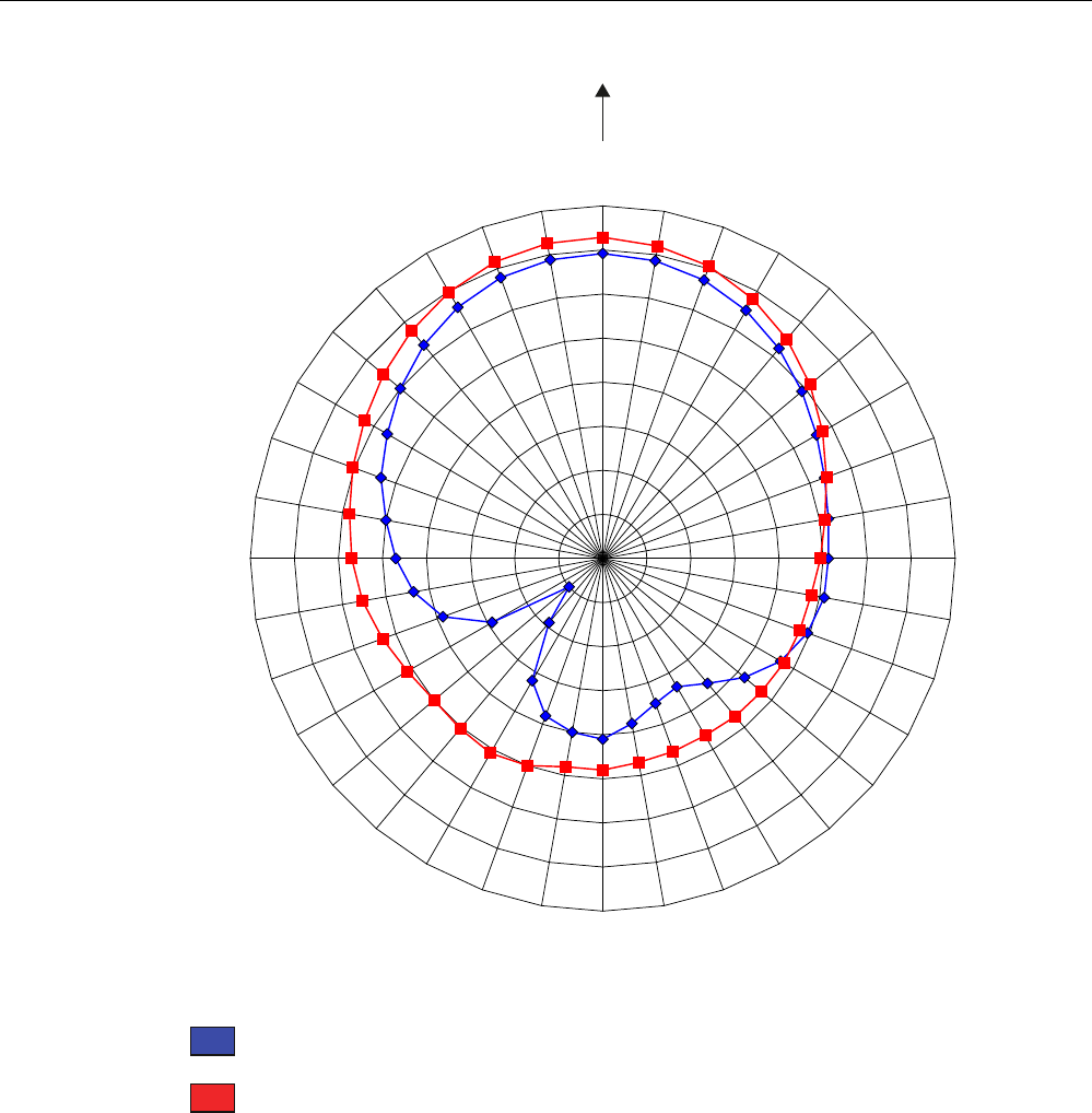
Pattern of the vertical plane of the antenna
Pattern of the horizontal plane of the antenna
Figure 6-14 The RF640A directional radiation pattern in the ETSI frequency band, polarization axis of
the transponder, and axis of symmetry of the antenna are parallel to each other.

Antennas
6.3 Antenna RF640A
SIMATIC RF600
220 System Manual, 05/2012, J31069-D0171-U001-A13-7618
Polarization axis and axis of symmetry are orthogonal to each other
In a configuration based on the following directional radiation pattern of the antenna, the axis
of symmetry of the antenna and the polarization axis of the transponder are orthogonal to
each other.
Antennas
6.3 Antenna RF640A
SIMATIC RF600
System Manual, 05/2012, J31069-D0171-U001-A13-7618 221
$PSOLILFDWLRQG%LF
$QJOHGHJUHHV
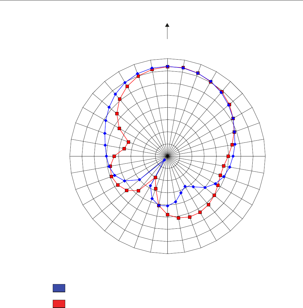
Pattern of the vertical plane of the antenna
Pattern of the horizontal plane of the antenna
Figure 6-15 The RF640A directional radiation pattern in the ETSI frequency band, axis of symmetry
of the antenna, and polarization axis of the transponder are orthogonal to each other
Antennas
6.3 Antenna RF640A
SIMATIC RF600
222 System Manual, 05/2012, J31069-D0171-U001-A13-7618
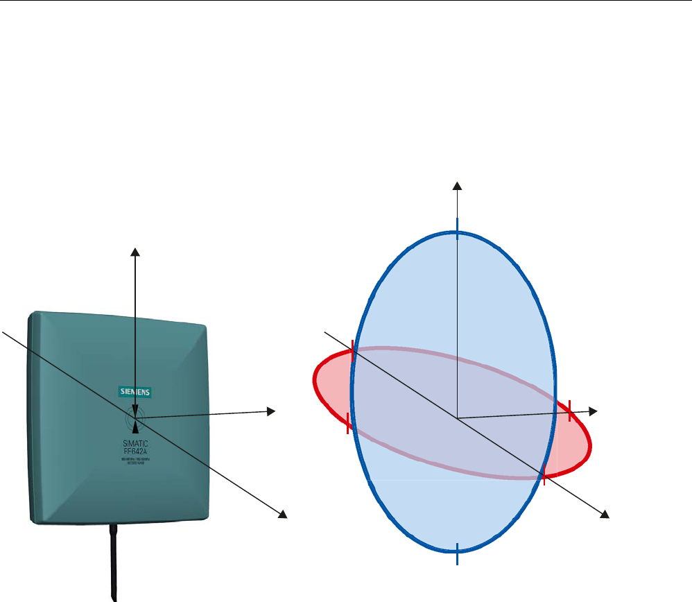
6.3.7.2 Antenna radiation patterns in the FCC frequency band
Directional radiation pattern USA (FCC)
The directional radiation pattern is shown for nominal alignment and a center frequency of
915 MHz.
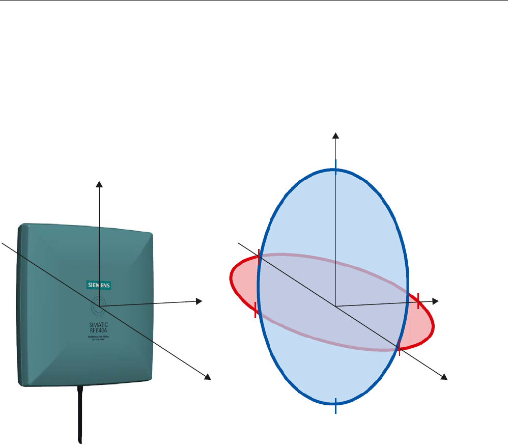
;
<
=
;
<
=
r
r
r
r
r
r
Figure 6-16 Reference system
The half-power beam width of the antenna is defined by the angle between the two -3 dB
points (corresponding to half the power referred to the maximum power). Which range (in %)
corresponds to the dB values in the patterns can be obtained from this table (Page 226).
Note that the measurements presented graphically below were carried out in a low-reflection
environment. Deviations can therefore occur in a normally reflecting environment.
Antennas
6.3 Antenna RF640A
SIMATIC RF600
System Manual, 05/2012, J31069-D0171-U001-A13-7618 223
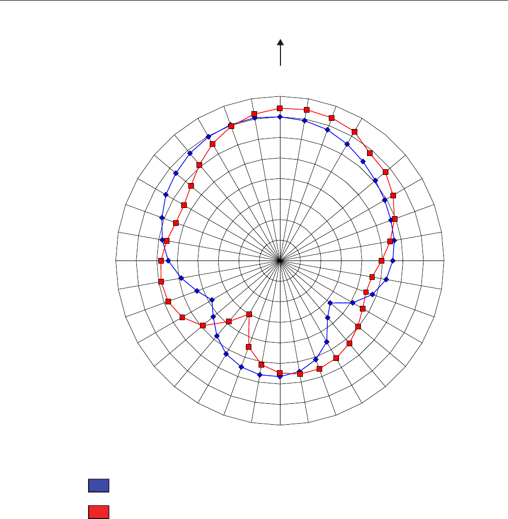
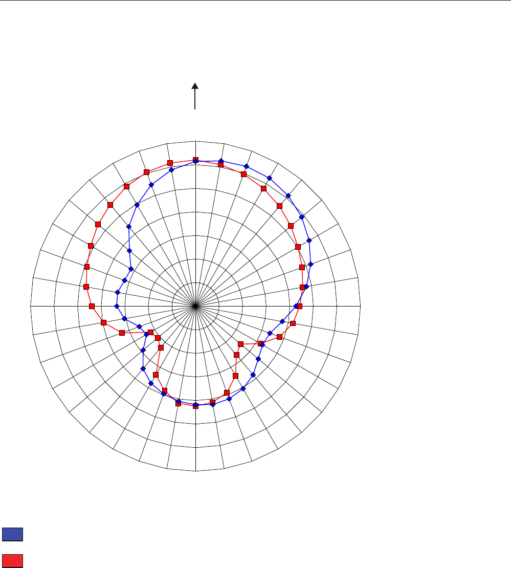
Directional radiation pattern in the FCC frequency band
Polarization axis and axis of symmetry are parallel
In the following directional radiation pattern of the antenna, the axis of symmetry of the
antenna and the polarization axis of the transponder are parallel.
Antennas
6.3 Antenna RF640A
SIMATIC RF600
224 System Manual, 05/2012, J31069-D0171-U001-A13-7618
$PSOLILFDWLRQG%LF
$QJOHGHJUHHV
Pattern of the vertical plane of the antenna
Pattern of the horizontal plane of the antenna
Figure 6-17 The RF640A directional radiation pattern in the FCC frequency band, polarization axis of
the transponder, and axis of symmetry of the antenna are parallel to each other
Antennas
6.3 Antenna RF640A
SIMATIC RF600
System Manual, 05/2012, J31069-D0171-U001-A13-7618 225
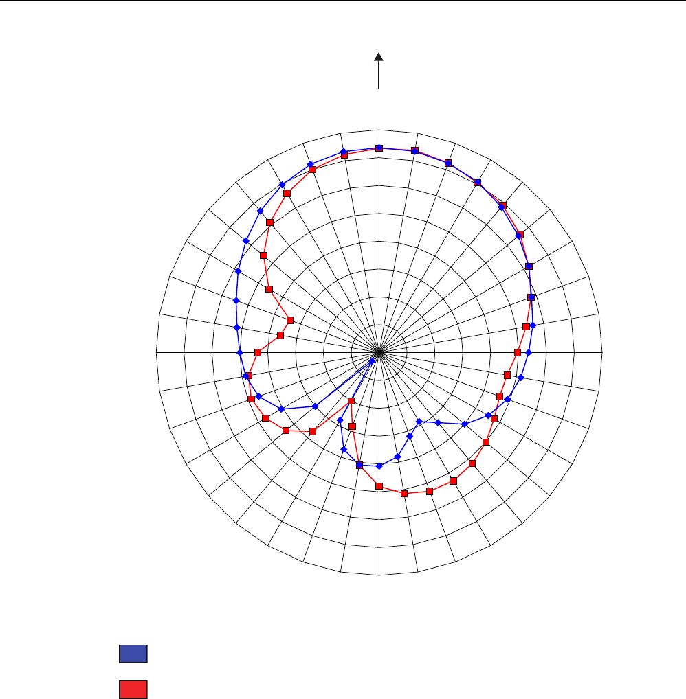
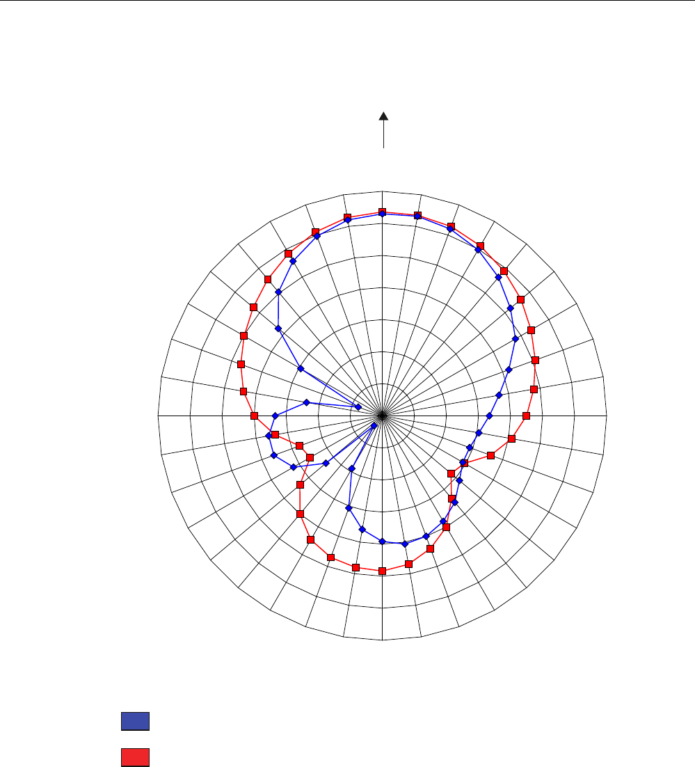
Polarization axis and axis of symmetry are orthogonal to each other
In the following directional radiation pattern of the antenna, the axis of symmetry of the
antenna and the polarization axis of the transponder are orthogonal to each other.
Antennas
6.3 Antenna RF640A
SIMATIC RF600
226 System Manual, 05/2012, J31069-D0171-U001-A13-7618
$PSOLILFDWLRQG%LF
$QJOHGHJUHHV
Pattern of the vertical plane of the antenna
Pattern of the horizontal plane of the antenna
Figure 6-18 The RF640A directional radiation pattern in the FCC frequency band, axis of symmetry
of the antenna, and polarization axis of the transponder are orthogonal to each other
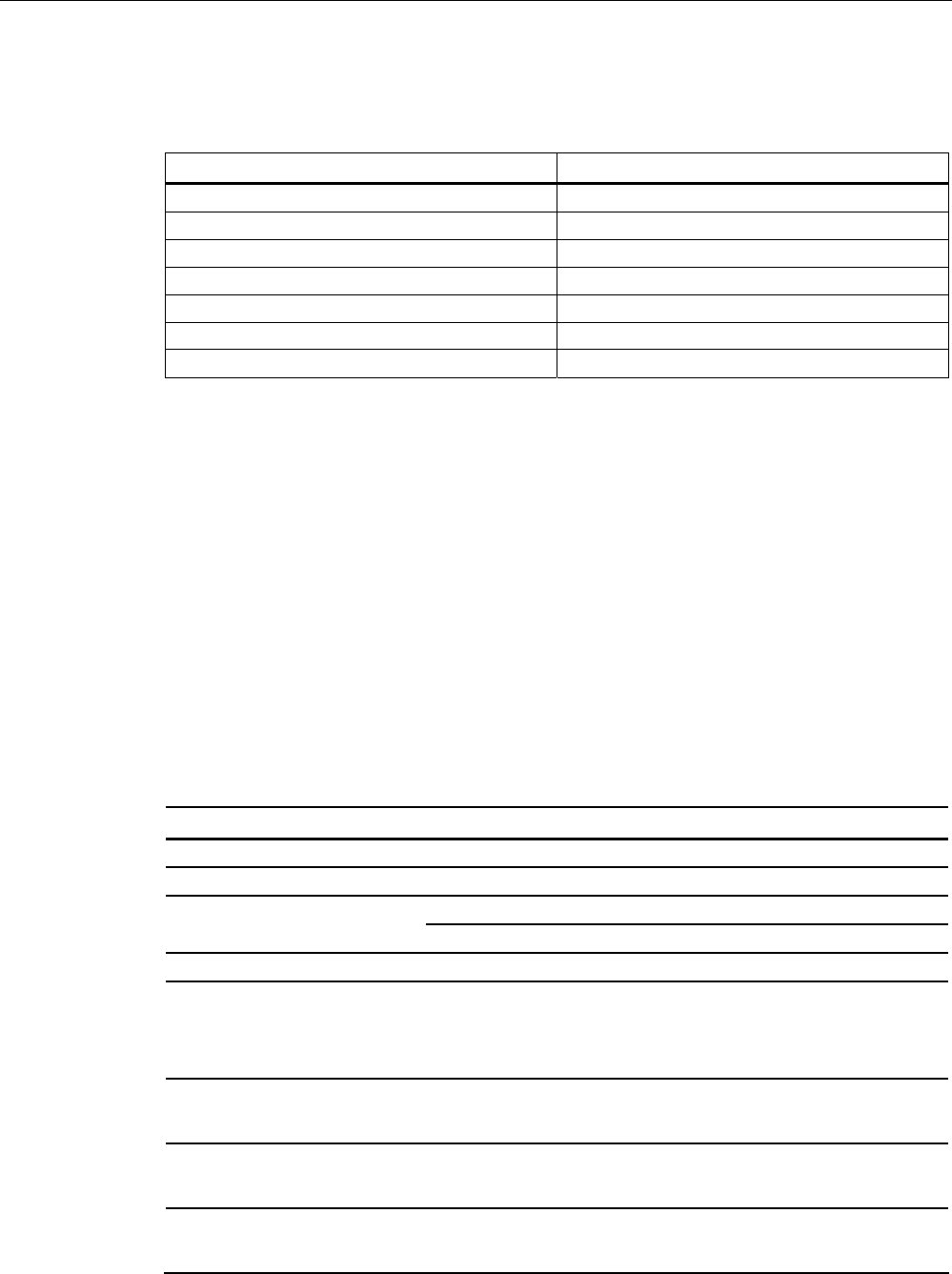
6.3.7.3 Interpretation of directional radiation patterns
The following overview table will help you with the interpretation of directional radiation
patterns.
The table shows which dBi values correspond to which read/write ranges (in %): You can
read the radiated power depending on the reference angle from the directional radiation
patterns, and thus obtain information on the read/write range with this reference angle with
regard to a transponder.
Antennas
6.3 Antenna RF640A
SIMATIC RF600
System Manual, 05/2012, J31069-D0171-U001-A13-7618 227
The dBr values correspond to the difference between the maximum dBi/dBic value and a
second dBi/dBic value.
Deviation from maximum antenna gain [dBr] Read/write range [%]
0 100
-3 70
-6 50
-9 35
-12 25
-15 18
-18 13
Example
As can be seen in Directional radiation patterns in the ETSI frequency band (Page 218), the
maximum antenna gain in the vertical plane is 3.45 dBi (6.45 dBic). In this plane, and with
the polarization axis of the transponder parallel to the axis of symmetry of the antenna, the
antenna gain drops to about 0.5 dBic at +50° or 310°. Therefore the dBr value is -6. The
antenna range is only 50% of the maximum range at + 50° or 310° from the Z axis within the
vertical plane (see values shown in blue in the directional radiation pattern: Characteristic of
the vertical plane of the antenna (Page 218) and the associated representation of the
reference system (Page 217)).
6.3.8 Technical data
Table 6- 12 General technical specifications RF640A
Feature SIMATIC RF640A
Dimensions (L x W x H) 185 x 185 x 45 mm
Color Pastel turquoise
PA 12 (polyamide 12) Material
Silicone-free
Frequency range 865 to 928 MHz
Plug connection 30 cm antenna connection coaxial cable with RTNC coupling, fixed
connection to antenna
An antenna cable is required for connection to the reader, e.g.:
6GT2815-0BH30
Max. radiated power
according to ETSI
• RF620R, RF630R: < 610 mW ERP
• RF640R, RF670R: ≤1300 mW ERP
Max. radiated power
according to CMIIT
• RF620R, RF630R: ≤650 mW ERP
• RF640R, RF670R: ≤ 1300 mW ERP
Max. radiated power
according to FCC
• RF620R, RF630R: ≤ 1070 mW EIRP
• RF640R, RF670R: ≤2700 mW EIRP

Antennas
6.3 Antenna RF640A
SIMATIC RF600
228 System Manual, 05/2012, J31069-D0171-U001-A13-7618
Feature SIMATIC RF640A
Max. power 2000 mW
Impedance 50 ohms
ETSI frequency band: 4 dBi (7 dBic) Antenna gain
FCC frequency band: 4.3 dBi (7.3 dBic)
ETSI frequency band: Max. 1.25 VSWR (standing wave ratio)
FCC frequency band: Max. 1.6
Polarization RH circular
ETSI frequency band:
• Horizontal plane: 80°
• Vertical plane: 75°
See ETSI antenna pattern
Aperture angle for
transmitting/receiving
FCC frequency band:
• Horizontal plane: 75°
• Vertical plane: 85°
See FCC antenna pattern
ETSI frequency band: 14 dB ± 2.4 dB
(depends on orientation of the transponder)
Front-to-back ratio
FCC frequency band: 9 dB ± 2.7 dB
(depends on orientation of the transponder)
Shock resistant to EN 60068-2-
27
30 g
Vibration resistant to EN 60068-
2-6
10 g
Attachment of the antenna 4 screws M4 (VESA 100 fastening system)
Tightening torque
(at room temperature)
≤ 2 Nm
Ambient temperature
• Operation
• Transport and storage
• -25 °C to +75 °C
• -40 °C to +85 °C
MTBF in years 445
Degree of protection according
to EN 60529
IP67
Weight, approx. 600 g
1) The values differ for different dimensions/materials of the mounting surface.
Antennas
6.3 Antenna RF640A
SIMATIC RF600
System Manual, 05/2012, J31069-D0171-U001-A13-7618 229
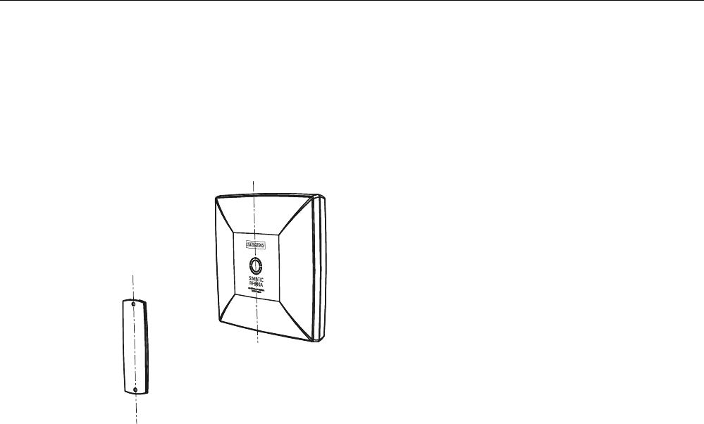
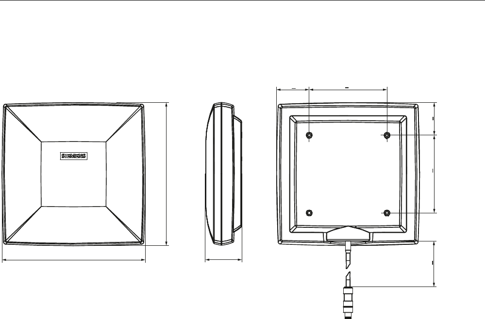
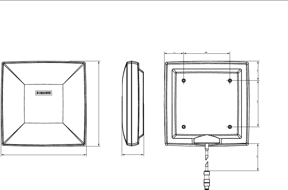
6.3.9 Dimension drawing
s
s
Figure 6-19 Dimension drawing RF640A
All dimensions in mm

Antennas
6.3 Antenna RF640A
SIMATIC RF600
230 System Manual, 05/2012, J31069-D0171-U001-A13-7618
6.3.10 Approvals & certificates
Table 6- 13 6GT2812-0GA08
Certificate Description
Conformity in accordance with R&TTE directive
in association with the readers and accessories used
Table 6- 14 6GT2812-0GA08
Standard
Federal Communications
Commission
FCC CFR 47, Part 15 sections 15.247
Radio Frequency Interference Statement
This equipment has been tested and found to comply with the limits
for a Class B digital device, pursuant to Part 15 of the FCC Rules.
The FCC approval is granted in association with the FCC approval of
the following RF600 readers:
• FCC ID: NXW-RF600R
(for RF620R: 6GT2811-5BA00-1AA1,
RF630R: 6GT2811-4AA00-1AA1,
RF640R: 6GT2811-3BA00-1AA0,
RF670R FS C1: 6GT2811-0AB00-1AA0)
• FCC ID: NXW-RF630R
(for 6GT2811-4AA00-1AA0)
• FCC ID: NXW-RF670
(for RF670R as of FS A1: 6GT2811-0AB00-1AA0
Industry Canada Radio
Standards Specifications
RSS-210 Issue 7, June 2007, Sections 2.2, A8
The approval for Industry Canada is granted in association with the
Industry Canada approval of the following RF600 readers:
• IC: 267X-RF630 (for 6GT2811-4AA00-1AA0)
• IC: 267X-RF670, RF670R FS A1 (for 6GT2811-0AB00-1AA0)
• IC: 267X-RF600R, Model RF620R-2 (for 6GT2811-5BA00-1AA1)
• IC: 267X-RF600R, Model RF630R-2 (for 6GT2811-4AA00-1AA1)
• IC: 267X-RF600R, Model RF640R (for 6GT2811-3BA00-1AA0)
• IC: 267X-RF600R, model RF670R-2 as of FS C1 (for 6GT2811-
0AB00-1AA0)
This product is UL-certified for the USA and Canada.
It meets the following safety standard(s):
UL 60950-1 - Information Technology Equipment Safety - Part 1:
General Requirements
CSA C22.2 No. 60950 -1 - Safety of Information Technology
Equipment
UL Report E 205089
Antennas
6.4 Antenna RF642A
SIMATIC RF600
System Manual, 05/2012, J31069-D0171-U001-A13-7618 231
6.4 Antenna RF642A
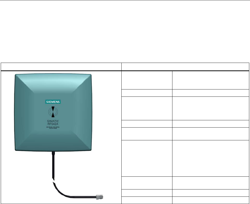
6.4.1 Description
SIMATIC RF642A Features
Field of application The SIMATIC RF642A is a universal
UHF antenna of compact, industry-
standard design with medium range.
Frequency range 865 to 928 MHz
Polarization Linear polarization
Suitable for RF600 transponders
that are uniformly aligned while
directed past the antenna.
Writing/reading range max. 5.0 m
Mounting 4 x M4
(VESA 100 fixing system)
Connector 30 cm connecting cable (connected
permanently to the antenna) and
RTNC coupling
An antenna cable is required for
connection to the reader, e.g.
6GT2815-0BH30)
Readers that can be
connected
All RF600 readers with external
antenna connectors
Dimensions in mm 185 x 185 x 45
Degree of protection IP67
Frequency ranges
The antenna is available for broadband. It can therefore be used for two different frequency
ranges that have been specified for the regions of Europe and China/USA respectively.
● The antenna for Europe (EU, EFTA countries) operates in the frequency range of 865 to
868 MHz.
● The antenna for China, the USA, and Canada operates in the frequency range of 902 to
928 MHz.
Function
The SIMATIC RF642A is used for transmitting and receiving RFID signals in the UHF range.
The antennas are connected to the SIMATIC RF600 readers via antenna cables that are
available in different lengths.
Antennas
6.4 Antenna RF642A
SIMATIC RF600
232 System Manual, 05/2012, J31069-D0171-U001-A13-7618
6.4.2 Ordering data
Table 6- 15 Ordering data RF642A
Product Order no.
SIMATIC RF642A 6GT2812-1GA08
Accessories
Table 6- 16 Ordering data (accessories)
Product Order no.
3 m (cable loss 1.0 dB) 6GT2815-0BH30
5 m, suitable for drag chains
(cable loss 1.25 dB)
6GT2815-2BH50
10 m (cable loss 2.0 dB) 6GT2815-1BN10
10 m (cable loss 4.0 dB) 6GT2815-0BN10
15 m, suitable for drag chains
(cable loss 4.0 dB)
6GT2815-2BN15
Connecting cable between
reader and antenna
20 m (cable loss 4.0 dB) 6GT2815-0BN20
Antenna mounting kit See "RF600 System Manual",
Chapter "Antennas" > "Mounting
types"
6GT2890-0AA00
6.4.3 Installation and assembly
6.4.3.1 RF640A mounting types
VESA 100 mounting system
A standardized VESA 100 mounting system is provided to mount the antenna. The mounting
system consists of four fixing holes for M4 screws at intervals of 100 mm.
This is therefore suitable for:
● Mounting on metallic and non-metallic backgrounds
Note
To achieve optimum wave propagation, the antenna should not be surrounded by
conducting objects. The area between antenna and transponder should also allow wave
propagation without interference.
Antennas
6.4 Antenna RF642A
SIMATIC RF600
System Manual, 05/2012, J31069-D0171-U001-A13-7618 233
Antenna Mounting Kit
The Antenna Mounting Kit allows the fine adjustment of the antenna field by setting the solid
angle (see "RF600 System Manual", chapter "Antennas" > "Mounting types").
6.4.4 Connecting an antenna to the reader
The SIMATIC RF642A antenna must be connected to the reader using an antenna cable.
Preassembled standard cables in lengths of 3 m, 10 m, and 20 m are available for the
connection.
The range of the antenna is limited by the cable loss. The maximum range can be achieved
with the cable 6GT2815-0BH30 (length 3 m), since this has the lowest cable loss.
Requirement
Note
Use of Siemens antenna cable
To ensure optimum functioning of the antenna, it is recommended that a Siemens antenna
cable be used in accordance with the list of accessories.
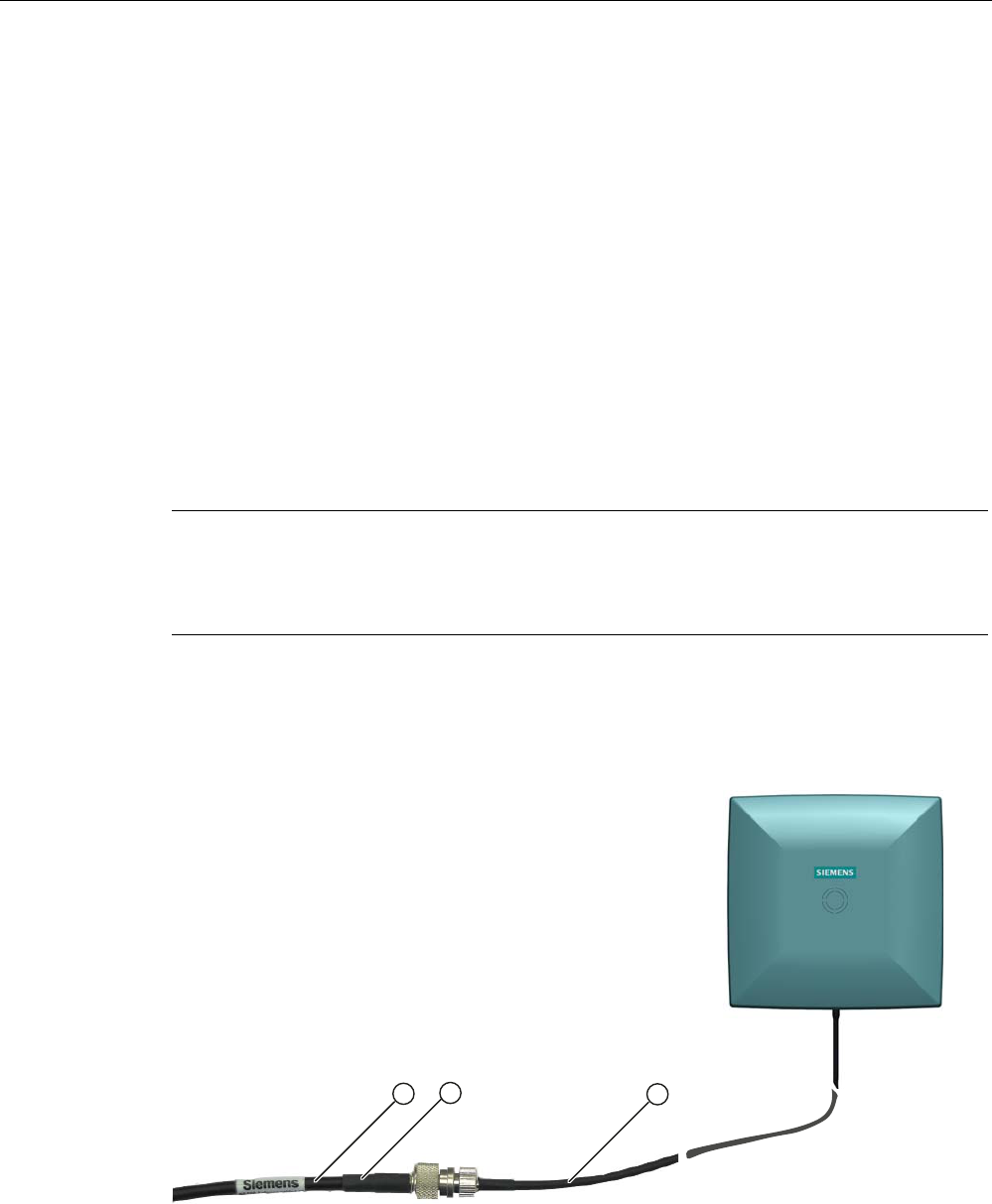
Strain relief
The antenna cable is provided with strain relief as shown in the following diagram:
① RF642A antenna connection (30 cm connecting cable)
② RF600 antenna cable
③ Strain relief (should take place at this position)
Figure 6-20 Strain relief

Antennas
6.4 Antenna RF642A
SIMATIC RF600
234 System Manual, 05/2012, J31069-D0171-U001-A13-7618
6.4.4.1 Bending radii and bending cycles of the cable
Cable
designation
Order No. Length [m] Cable loss
[dB]
Bending
radius [mm]
Bending cycle
RF642A antenna
connection
Fixed
connection to
antenna
0,3 - - 1 Mal
Antenna cable 6GT2815-
0BH30
3 1 51 1 Mal
Antenna cable
(suitable for drag
chains)
6GT2815-
2BH50
5 1,25 48 1)
Antenna cable 6GT2815-
1BN10
10 2 77 1 Mal
Antenna cable 6GT2815-
0BN10
10 4 51 1 Mal
Antenna cable
(suitable for drag
chains)
6GT2815-
0BN20
15 4 24 1)
Antenna cable 6GT2815-
0BN20
20 4 77 1 Mal
1) With cables suitable for drag chains, 3 million bending cycles at a bending radius of 6.5 m and
bending through ± 180 ° are permitted.
Antennas
6.4 Antenna RF642A
SIMATIC RF600
System Manual, 05/2012, J31069-D0171-U001-A13-7618 235
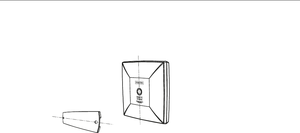
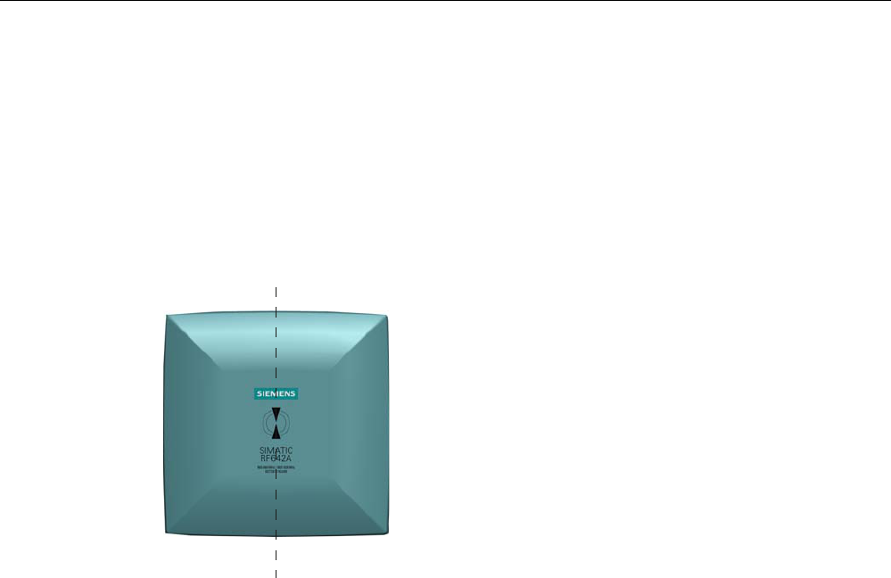
6.4.5 Alignment of transponders to the antenna
Polarization axis
Since the RF642A antenna has linear polarization, it is necessary to consider the alignment
of the transponders with regard to the polarization axis of the antenna.
The polarization axes of antenna and transponder must always be parallel. The symbol on
the antenna indicates the polarization axis.
3RODUL]DWLRQD[LV
Figure 6-21 Polarization axis
Antennas
6.4 Antenna RF642A
SIMATIC RF600
236 System Manual, 05/2012, J31069-D0171-U001-A13-7618
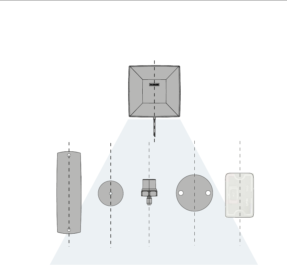
Alignment
The following diagram shows the optimum alignment of the RF600 transponders to the
RF642A antenna.
6,0$7,&5)$
5)7
5)7
5)7 5)7
5)7*HQ
5)/
5)/
)57
5)7
Figure 6-22 Antenna/transponder alignment
Antennas
6.4 Antenna RF642A
SIMATIC RF600
System Manual, 05/2012, J31069-D0171-U001-A13-7618 237
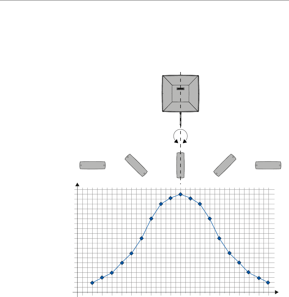
Angle deviation diagram for alignment
The following diagram shows the dependence of the following factors.
● Alignment angle of transponder to antenna
● Maximum range of antenna
6,0$7,&5)$
$QJOHGHYLDWLRQRIWKHSRODUL]DWLRQD[HVRIDQWHQQDDQGWDJ>GHJUHHV@
0D[UDQJH>@
r r r r r r r r rr r r r r r rr r
Figure 6-23 Angle deviation diagram for alignment

Antennas
6.4 Antenna RF642A
SIMATIC RF600
238 System Manual, 05/2012, J31069-D0171-U001-A13-7618
6.4.6 Parameter settings of RF642A for RF620R/RF630R
Operation within the EU, EFTA, or Turkey according to EN 302 208 V1.3.1
NOTICE
Limitation of the radiated power according to EN 302 208 V1.3.1
RF600 systems that are put into operation within the EU, EFTA, or Turkey (ETSI) can be
operated with an RF642A antenna with a maximum radiated power of up to 2000 mW ERP
(or 33 dBm ERP, 3250 mW EIRP, 35 dBm EIRP).
By adjusting the transmit power of up to 500 mW ERP (or 27 dBm ERP, 800 mW EIRP,
29.15 dBm EIRP) and taking into account the RF642A antenna gain of 4 dBi (6 dBic) and the
cable loss associated with the antenna cable (see table), the radiated power of the antenna
cannot be exceeded. You can make the power settings using the "distance_limiting"
parameter. You will find more detailed information on the parameters in the section
Parameter assignment manual RF620R/RF630R
(http://support.automation.siemens.com/WW/view/en/33287195).
Operation in China
The national approval for RF600 systems in China requires a cap of 2000 mW ERP (or
33 dBm ERP, 3250 mW EIRP, 35 dBm EIRP). The possible combination of antenna gain,
cable loss, and max. 500 mW radiated power of the RF630R reader means it is not possible
to exceed 2000 mW ERP (or 33 dBm ERP, 3250 mW EIRP, 35 dBm EIRP).
Operation in the USA, Canada
NOTICE
Limitation of the radiated power to 4000 mW EIRP (36 dBm EIRP) with an antenna gain of
7 dBi
The antenna must be commissioned by qualified personnel. Antennas with a gain >6 dBi
may be commissioned, as long as the effective radiated power of 4000 mW EIRP
(36 dBm EIRP) is not exceeded.
To comply with FCC and IC-FCB requirements, the system must satisfy the following
relation:
• Conducted power P dBm of the RF600 reader (< 30 dBm)
• Antenna gain Gi dBi in the FCC frequency band (≤ 7 dBi)
• Cable loss ak dB (≥ 1 dB)
P(dBm) ≤ 30 dBm - (Gi - 6 dBi) + ak

Antennas
6.4 Antenna RF642A
SIMATIC RF600
System Manual, 05/2012, J31069-D0171-U001-A13-7618 239
6.4.7 Parameter settings of RF642A for RF640R/RF670R
Operation within the EU, EFTA, or Turkey
NOTICE
Limitation of the radiated power according to EN 302 208 V1.3.1
RF600 systems that are put into operation within the EU, EFTA, or Turkey (ETSI) can be
operated with an RF642A antenna with a maximum radiated power of 2000 mW ERP (or 33
dBm ERP, 3250 mW EIRP, 35 dBm EIRP).
By adjusting the radiated power of up to 2000 mW ERP (or 33 dBm ERP, 3250 mW EIRP,
35 dBm EIRP), the RF642A antenna gain of 6 dBi and the cable loss associated with the
antenna cable (see table), the radiated power of the reader is correctly configured and the
radiated power at the antenna is thus not exceeded.
Operation in China
By setting a max. radiated power of 2000 mW ERP (or 33 dBm ERP, 3250 mW EIRP, 35
dBm EIRP), the RF642A antenna gain of 7 dBi and the cable loss associated with the
antenna cable (see table), the radiated power is correctly configured in the reader.
Operation in the USA, Canada
NOTICE
Limitation of the radiated power to 4000 mW EIRP (36 dBm EIRP) with an antenna gain of
7 dBi
The antenna must be commissioned by qualified personnel. Antennas with a gain >6 dBi
may be commissioned, as long as the effective radiated power of 4000 mW EIRP
(36 dBm EIRP) is not exceeded.
To comply with FCC and IC-FCB requirements, the system must satisfy the following
relation:
• Conducted power P dBm of the RF600 reader (< 30 dBm)
• Antenna gain Gi dBi in the FCC frequency band (≤ 7 dBi)
• Cable loss ak dB (≥ 1 dB)
P(dBm) ≤ 30 dBm - (Gi - 6 dBi) + ak
Antennas
6.4 Antenna RF642A
SIMATIC RF600
240 System Manual, 05/2012, J31069-D0171-U001-A13-7618
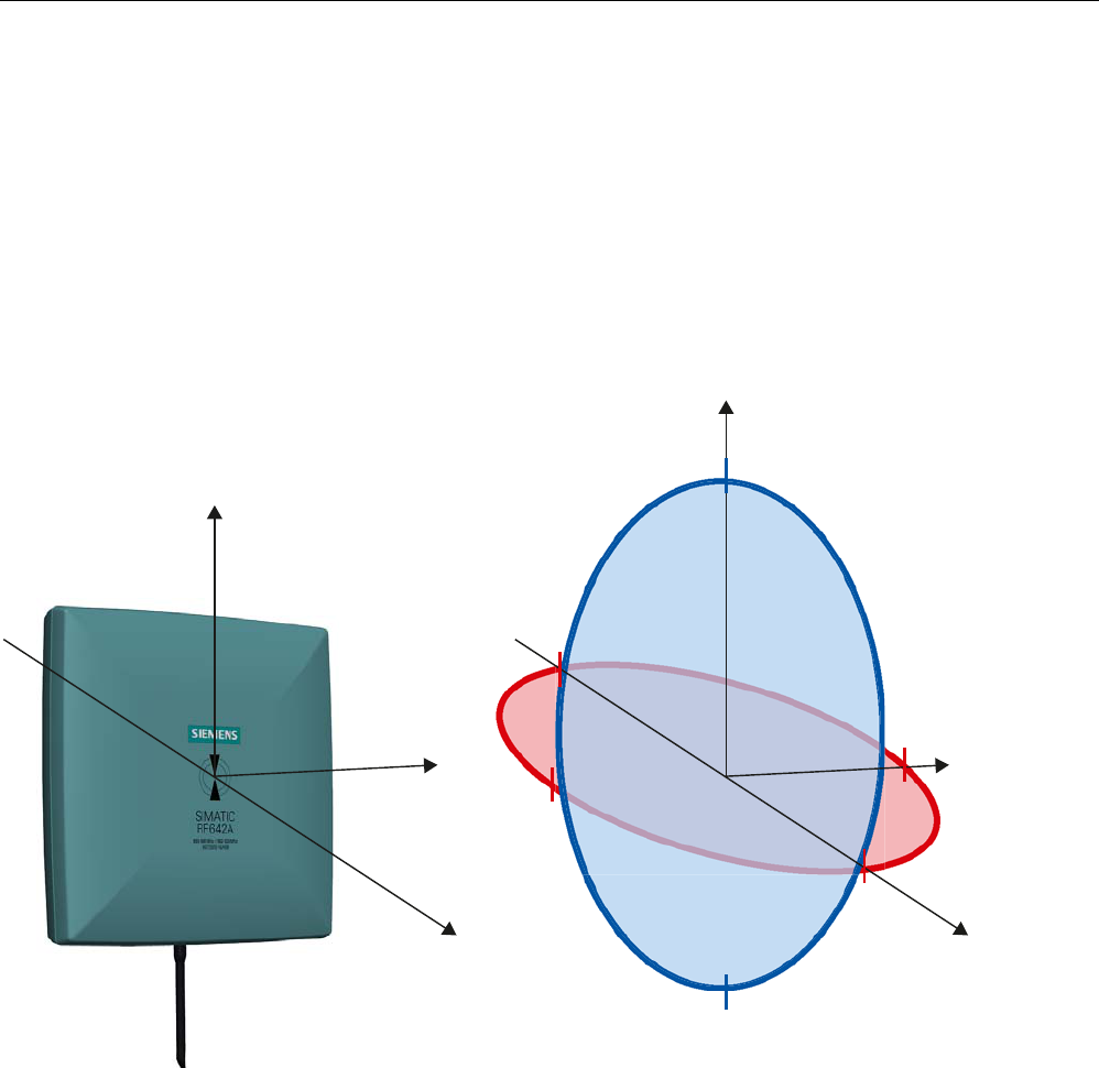
6.4.8 Antenna patterns
6.4.8.1 Antenna radiation patterns in the ETSI frequency band
Directional radiation pattern Europe (ETSI)
The directional radiation pattern is shown for nominal alignment and a center frequency of
866.3 MHz. The nominal antenna alignment is given when the antenna elevation is provided
as shown in the following figure.
;
<
=
;
<
=
r
r
r
r
r
r
Figure 6-24 Reference system
The half-power beam width of the antenna is defined by the angle between the two -3 dB
points. Which range (in %) corresponds to the dB values in the patterns can be obtained
from this table .
Note that the measurements presented graphically below were carried out in a low-reflection
environment. Deviations can therefore occur in a normally reflecting environment.
Antennas
6.4 Antenna RF642A
SIMATIC RF600
System Manual, 05/2012, J31069-D0171-U001-A13-7618 241
Directional radiation pattern in the ETSI frequency band
$PSOLILFDWLRQG%L
$QJOHGHJUHHV
Pattern of the vertical plane of the antenna
Pattern of the horizontal plane of the antenna
Figure 6-25 Directional radiation pattern of RF642A in the ETSI frequency band
Antennas
6.4 Antenna RF642A
SIMATIC RF600
242 System Manual, 05/2012, J31069-D0171-U001-A13-7618
6.4.8.2 Antenna radiation patterns in the FCC frequency band
Directional radiation pattern USA (FCC)
The directional radiation pattern is shown for nominal alignment and a center frequency of
915 MHz.
;
<
=
;
<
=
r
r
r
r
r
r
Figure 6-26 Reference system
The half-power beam width of the antenna is defined by the angle between the two -3 dB
points (corresponding to half the power referred to the maximum power). Which range (in %)
corresponds to the dB values in the patterns can be obtained from this table .
Note that the measurements presented graphically below were carried out in a low-reflection
environment. Deviations can therefore occur in a normally reflecting environment.
Antennas
6.4 Antenna RF642A
SIMATIC RF600
System Manual, 05/2012, J31069-D0171-U001-A13-7618 243
Directional radiation pattern of the RF642A in the FCC frequency band
$PSOLILFDWLRQG%L
$QJOHGHJUHHV
Pattern of the vertical plane of the antenna
Pattern of the horizontal plane of the antenna
Figure 6-27 Directional radiation pattern of the RF642A in the FCC frequency band

Antennas
6.4 Antenna RF642A
SIMATIC RF600
244 System Manual, 05/2012, J31069-D0171-U001-A13-7618
6.4.8.3 Interpretation of directional radiation patterns
The following overview table will help you with the interpretation of directional radiation
patterns.
The table shows which dBi values correspond to which read/write ranges (in %): You can
read the radiated power depending on the reference angle from the directional radiation
patterns, and thus obtain information on the read/write range with this reference angle with
regard to a transponder.
The dBr values correspond to the difference between the maximum dBi value and a second
dBi value.
Deviation from maximum antenna gain [dBr] Read/write range [%]
0 100
-3 70
-6 50
-9 35
-12 25
-15 18
-18 13
Example
As can be seen in Directional radiation pattern in the ETSI frequency band (Page 241), the
maximum antenna gain in the horizontal plane is 6 dBi. In this plane and with the parallel
polarization axis at +70° or 300°, the antenna gain dropped to about 0 dBi. Therefore the dBr
value is 6. The antenna range is only 70° of the maximum range at + 50° or +300° from the Z
axis within the horizontal plane (see values shown in red in the directional radiation pattern:
Characteristic of the vertical plane of the antenna and the associated representation of the
reference system).
6.4.9 Technical data
Table 6- 17 General technical specifications RF642A
Feature SIMATIC RF642A
Dimensions (L x W x H) 185 x 185 x 45 mm
Color Pastel turquoise
PA 12 (polyamide 12) Material
Silicone-free
Frequency range 865 to 928 MHz
Plug connection 30 cm coaxial cable with RTNC coupling
An antenna cable is required for connection to the reader, e.g.:
6GT2815-0BH30

Antennas
6.4 Antenna RF642A
SIMATIC RF600
System Manual, 05/2012, J31069-D0171-U001-A13-7618 245
Feature SIMATIC RF642A
Max. radiated power
according to ETSI
• RF620R, RF630R: < 970 mW ERP
• RF640R, RF670R: ≤ 1900 mW ERP
Max. radiated power
according to CMIIT
• RF620R, RF630R: < 1200 mW ERP
• RF640R, RF670R: ≤ 2000 mW ERP
Max. radiated power
according to FCC
• RF620R, RF630R: ≤2000 mW EIRP
• RF640R, RF670R: ≤4000 mW EIRP
Max. power 2000 mW
Impedance 50 ohms
ETSI frequency band: 6 dBi Antenna gain
FCC frequency band: 7 dBi
VSWR (standing wave ratio) max.: 1.4
Polarization Linear polarization
ETSI frequency band:
• Horizontal plane: 75°
• Vertical plane: 70°
See ETSI antenna pattern
Aperture angle for
transmitting/receiving
FCC frequency band:
• Horizontal plane: 80°
• Vertical plane: 70°
See FCC antenna pattern
ETSI frequency band: 10 dB Front-to-back ratio
FCC frequency band: 9.8 dB ± 2.2 dB
Shock resistant to EN 60068-2-
27
30 g
Vibration resistant to EN 60068-
2-6
10 g
Attachment of the antenna 4 screws M4 (VESA 100 fastening system)
Tightening torque
(at room temperature)
≤ 2 Nm
Ambient temperature
• Operation
• Transport and storage
• -25 °C to +75 °C
• -40 °C to +85 °C
MTBF in years 16880
Degree of protection according
to EN 60529
IP65
Weight, approx. 600 g
1) The values differ for different dimensions/materials of the mounting surface.
Antennas
6.4 Antenna RF642A
SIMATIC RF600
246 System Manual, 05/2012, J31069-D0171-U001-A13-7618
6.4.10 Dimension drawing
s
s
Figure 6-28 Dimensional drawing of RF642A
All dimensions in mm
Antennas
6.4 Antenna RF642A
SIMATIC RF600
System Manual, 05/2012, J31069-D0171-U001-A13-7618 247
6.4.11 Approvals & certificates
Table 6- 18 6GT2812-1GA08
Certificate Description
Conformity in accordance with R&TTE directive
in association with the readers and accessories used
Table 6- 19 6GT2812-1GA08
Standard
Federal Communications
Commission
FCC CFR 47, Part 15 sections 15.247
Radio Frequency Interference Statement
This equipment has been tested and found to comply with the limits
for a Class B digital device, pursuant to Part 15 of the FCC Rules.
The FCC approval is granted in association with the FCC approval of
the following RF600 readers:
• FCC ID: NXW-RF600R
(for RF620R: 6GT2811-5BA00-1AA1,
RF630R: 6GT2811-4AA00-1AA1,
RF640R: 6GT2811-3BA00-1AA0,
RF670R as of FS C1: 6GT2811-0AB00-1AA0)
• FCC ID: NXW-RF630R
(for 6GT2811-4AA00-1AA0)
• FCC ID: NXW-RF670
(for RF670R as of FS A1: 6GT2811-0AB00-1AA0)
Industry Canada Radio
Standards Specifications
RSS-210 Issue 7, June 2007, Sections 2.2, A8
The approval for Industry Canada is granted in association with the
Industry Canada approval of the following RF600 readers:
• IC: 267X-RF630 (for 6GT2811-4AA00-1AA0)
• IC: 267X-RF670, RF670R FS A1 (for 6GT2811-0AB00-1AA0)
• IC: 267X-RF600R, Model RF620R-2 (for 6GT2811-5BA00-1AA1)
• IC: 267X-RF600R, Model RF630R-2 (for 6GT2811-4AA00-1AA1)
• IC: 267X-RF600R, Model RF640R (for 6GT2811-3BA00-1AA0)
• IC: 267X-RF600R, model RF670R-2 as of FS C1 (for 6GT2811-
0AB00-1AA0)
This product is UL-certified for the USA and Canada.
It meets the following safety standard(s):
UL 60950-1 - Information Technology Equipment Safety - Part 1:
General Requirements
CSA C22.2 No. 60950 -1 - Safety of Information Technology
Equipment
UL Report E 205089
Antennas
6.5 RF660A antenna
SIMATIC RF600
248 System Manual, 05/2012, J31069-D0171-U001-A13-7618
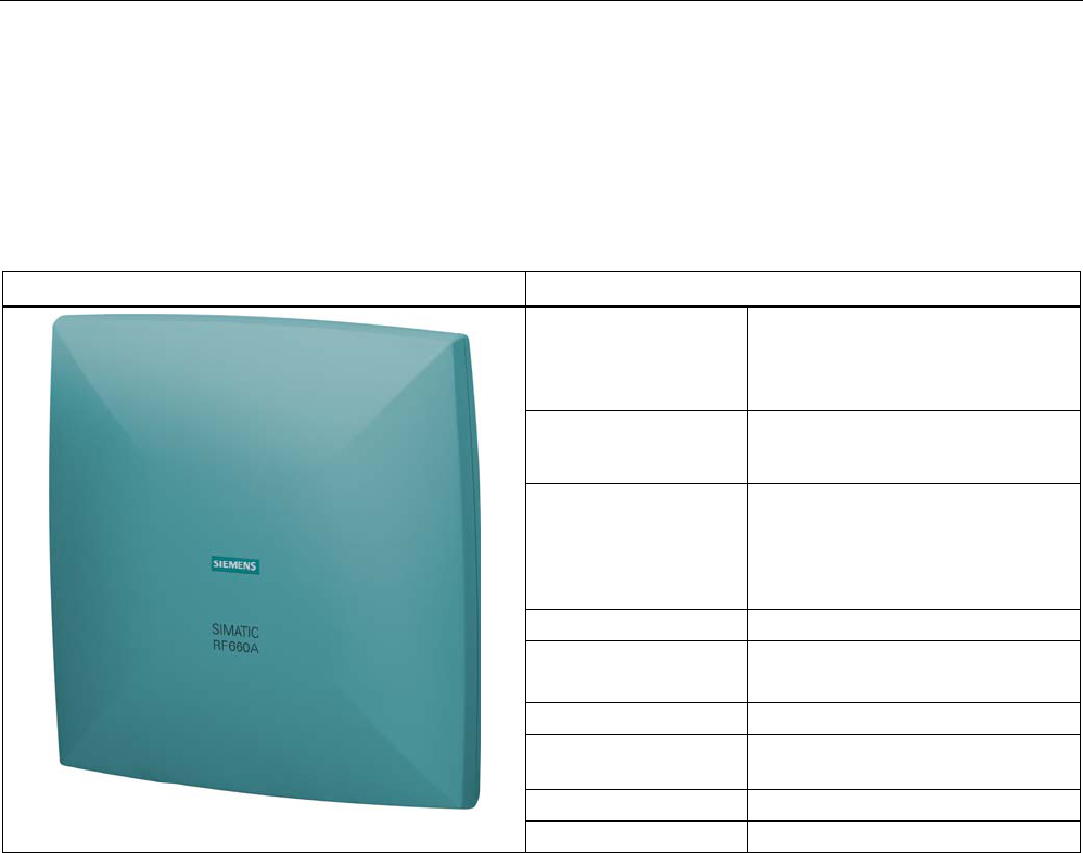
6.5 RF660A antenna
6.5.1 Description
SIMATIC RF660A Features
Field of application The SIMATIC RF660A is a universal
medium range UHF antenna with a
compact design suitable for use in
industry.
Frequency ranges • 865 to 928 MHz (ETSI)
• 902 to 928 MHz (FCC)
Polarization RH circular
Suitable for RF600 transponders
that can pass in parallel with the
antenna regardless of their
orientation.
Writing/reading range max. X m
Mounting 4 x M4
(VESA 100 mounting system)
Connector RTNC
Readers that can be
connected
All RF600 readers with external
antenna connectors
Dimensions in mm 313 x 313 x 80
Degree of protection IP67
Frequency ranges
The antenna is available for broadband. It can therefore be used for two different frequency
ranges that have been specified for the regions of Europe and China/USA respectively.
● The antenna for Europe (EU, EFTA countries) operates in the frequency range of 865 to
868 MHz.
● The antenna for China, the USA, and Canada operates in the frequency range of 902 to
928 MHz.
Function
The SIMATIC RF660A is used to transmit and receive RFID signals in the UHF range. The
antennas are connected to the SIMATIC RF600 readers via antenna cables that are
available in different lengths.
Antennas
6.5 RF660A antenna
SIMATIC RF600
System Manual, 05/2012, J31069-D0171-U001-A13-7618 249
Ordering data
Description Machine-Readable Product Code
RF660A antenna for Europe (865-868) 6GT2812-0AA00
RF660A antenna for China and the USA (902-928) 6GT2812-0AA01
Ordering data (accessories)
Description Machine-Readable Product Code
Antenna mounting kit 6GT2890-0AA00
3 m
(1 dB cable attenuation)
6GT2815-0BH30
5 m, suitable for drag
chains (cable loss
1.25 dB)
6GT2815-2BH50
10 m
(2 dB cable attenuation)
6GT2815-1BN10
10 m
(4 dB cable attenuation)
6GT2815-0AN10
15 m, suitable for drag
chains (cable loss 4.0 dB)
6GT2815-2BN15
Connecting cable between reader
and antenna
20 m
(4 dB cable attenuation)
6GT2815-0AN20
6.5.2 Installation and assembly
6.5.2.1 RF660A mounting types
VESA 100 mounting system
A standardized VESA 100 mounting system is provided to mount the antenna. The mounting
system consists of four fixing holes for M4 screws at intervals of 100 mm.
This is therefore suitable for:
● Mounting on metallic and non-metallic backgrounds
Note
To achieve optimum wave propagation, the antenna should not be surrounded by
conducting objects. The area between antenna and transponder should also allow wave
propagation without interference.
Antennas
6.5 RF660A antenna
SIMATIC RF600
250 System Manual, 05/2012, J31069-D0171-U001-A13-7618
Antenna Mounting Kit
The Antenna Mounting Kit allows the fine adjustment of the antenna field by setting the solid
angle (see "RF600 System Manual", chapter "Antennas" > "Mounting types").
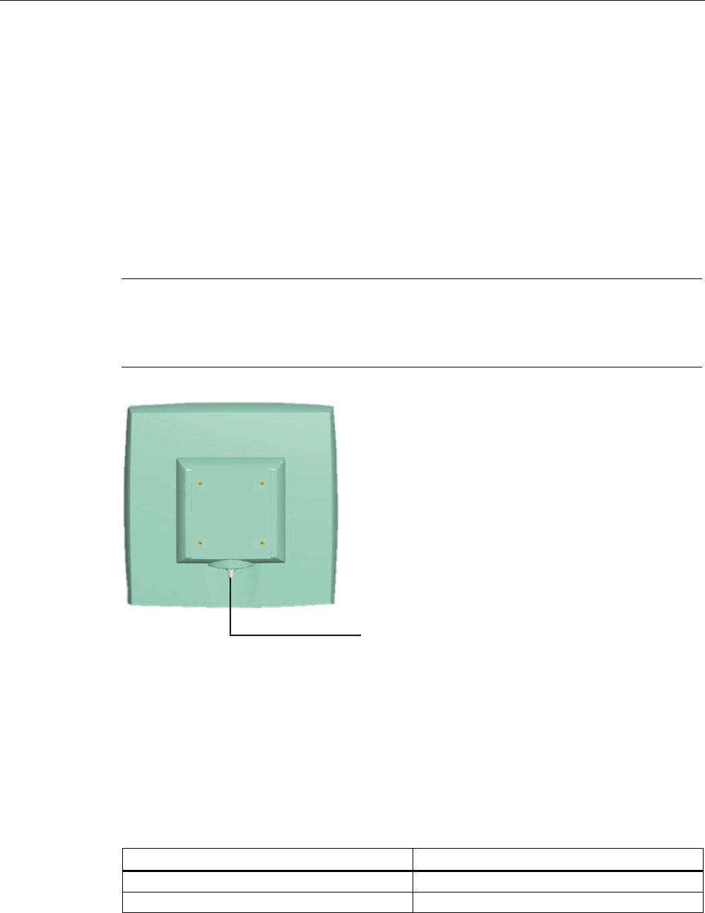
6.5.3 Connecting an antenna to a reader
The SIMATIC RF660A antenna must be connected to the reader using an antenna cable.
Requirement
Note
Use of Siemens antenna cable
To ensure optimum functioning of the antenna, it is recommended that a Siemens antenna
cable is used in accordance with the list of accessories.
Figure 6-29 Rear of antenna with RTNC connection
Connecting RF660A to RF640R/RF670R
Preassembled standard cables in lengths of 3 m, 10 m and 20 m are available for
connection.
The cable between antenna and reader can be up to 20 m in length.
When less than four antennas are used, we recommend that the antennas are connected to
the reader as follows:
Number of antennas Connections on the reader
2 antennas ANT 1, ANT 2
3 antennas ANT 1, ANT 2, ANT 3

Antennas
6.5 RF660A antenna
SIMATIC RF600
System Manual, 05/2012, J31069-D0171-U001-A13-7618 251
Connecting RF660A to RF630R
Preassembled standard cables in lengths of 3 m, 10 m and 20 m are available for
connection.
The cable between antenna and reader can be up to 20 m in length.
When one antenna is used, it is recommended that the remaining antenna connection is
sealed using the supplied protective cap.
6.5.3.1 Bending radii and bending cycles of the cable
Cable
designation
Order No. Length [m] Cable loss
[dB]
Bending
radius [mm]
Bending cycle
Antenna cable 6GT2815-
0BH30
3 1 51 1 Mal
Antenna cable
(suitable for drag
chains)
6GT2815-
2BH50
5 1,25 1) 1)
Antenna cable 6GT2815-
1BN10
10 2 77 1 Mal
Antenna cable 6GT2815-
0BN10
10 4 51 1 Mal
Antenna cable
(suitable for drag
chains)
6GT2815-
0BN20
15 4 1) 1)
Antenna cable 6GT2815-
0BN20
20 4 77 1 Mal
1) With cables suitable for drag chains, 3 million bending cycles at a bending radius of 6.5 mm and
bending through ± 180° are permitted.
6.5.4 Parameter settings of RF660A for RF620R/RF630R
Operation within the EU, EFTA, or Turkey
NOTICE
Limitation of the radiated power according to EN 302 208 V1.3.1
RF600 systems that are put into operation within the EU, EFTA, or Turkey (ETSI) can be
operated with an RF660A antenna with a maximum radiated power of up to 2000 mW ERP
(or 33 dBm ERP, 3250 mW EIRP, 35 dBm EIRP).

Antennas
6.5 RF660A antenna
SIMATIC RF600
252 System Manual, 05/2012, J31069-D0171-U001-A13-7618
By adjusting the transmit power of up to 500 mW ERP (or 27 dBm ERP, 800 mW EIRP,
29.15 dBm EIRP) and taking into account the RF660A antenna gain of 7 dBi (9 dBic) and the
cable loss associated with the antenna cable (see table (Page 251)), the radiated power of
the antenna cannot be exceeded. You can make the power settings using the
"distance_limiting" parameter. You will find more detailed information on the parameters in
the section Parameter assignment manual RF620R/RF630R
(http://support.automation.siemens.com/WW/view/en/33287195).
Operation in China
The national approval for RF600 systems in China requires a cap of 2000 mW ERP (or
33 dBm ERP, 3250 mW EIRP, 35 dBm EIRP). The possible combination of antenna gain,
cable loss, and max. 500 mW radiated power of the RF620R/RF630R reader means it is not
possible to exceed 2000 mW ERP (or 33 dBm ERP, 3250 mW EIRP, 35 dBm EIRP).
Operation in the USA, Canada
NOTICE
Limitation of the radiated power to 4000 mW EIRP (36 dBm EIRP)
So that the FCC and IC-FCB requirements are met, the radiated power may not exceed
4000 mW EIRP (36 dBm EIRP). Therefore the system must satisfy the following relation:
• Conducted power P dBm of the RF600 reader (< 30 dBm)
• Antenna gain Gi dBi in the FCC frequency band (≤ 4.3 dBi)
• Cable loss ak dB (≥ 1 dB)
P(dBm) ≤ 30 dBm - (Gi - 6 dBi) + ak
6.5.5 Parameter settings of RF660A for RF640R/RF670R
Operation within the EU, EFTA, or Turkey
NOTICE
Limitation of the radiated power according to EN 302 208 V1.3.1
RF600 systems that are put into operation within the EU, EFTA, or Turkey (ETSI) can be
operated with an RF660A antenna with a maximum radiated power of 2000 mW ERP (or 33
dBm ERP, 3250 mW EIRP, 35 dBm EIRP).
By adjusting the radiated power of up to 1300 mW ERP (or 31.15 dBm ERP,
2140 mW EIRP, 33.3 dBm EIRP), the RF660A antenna gain of 7 dBi (9 dBic) and the cable
loss associated with the antenna cable (see table (Page 251)), the radiated power of the
reader is correctly configured and the radiated power at the antenna is not exceeded.

Antennas
6.5 RF660A antenna
SIMATIC RF600
System Manual, 05/2012, J31069-D0171-U001-A13-7618 253
Operation in China
By setting a max. radiated power of 1300 mW ERP (or 31.15 dBm ERP, 2140 mW EIRP,
33.3 dBm EIRP), the RF660A antenna gain of 6 dBi (8 dBic) and the cable loss associated
with the antenna cable (see table (Page 251)), the radiated power of the reader is correctly
configured.
Operation in the USA, Canada
NOTICE
Limitation of the radiated power to 4000 mW EIRP (36 dBm EIRP)
So that the FCC and IC requirements are met, the radiated power may not exceed 4000
mW EIRP (36 dBm EIRP). Therefore the system must satisfy the following relation:
• Conducted power P dBm of the RF600 reader (< 30 dBm)
• Antenna gain Gi dBi in the FCC frequency band (≤ 4.3 dBi)
• Cable loss ak dB (≥ 1 dB)
P(dBm) ≤ 30 dBm - (Gi - 6 dBi) + ak
6.5.6 Antenna patterns
6.5.6.1 Antenna pattern
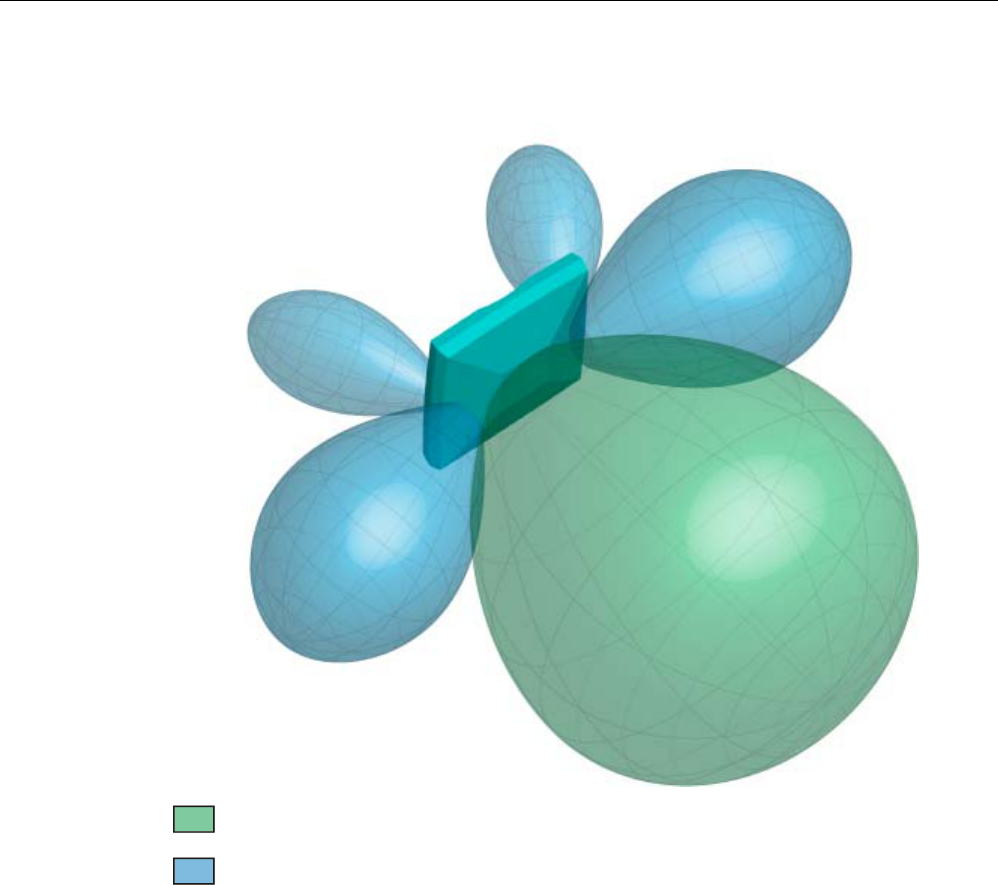
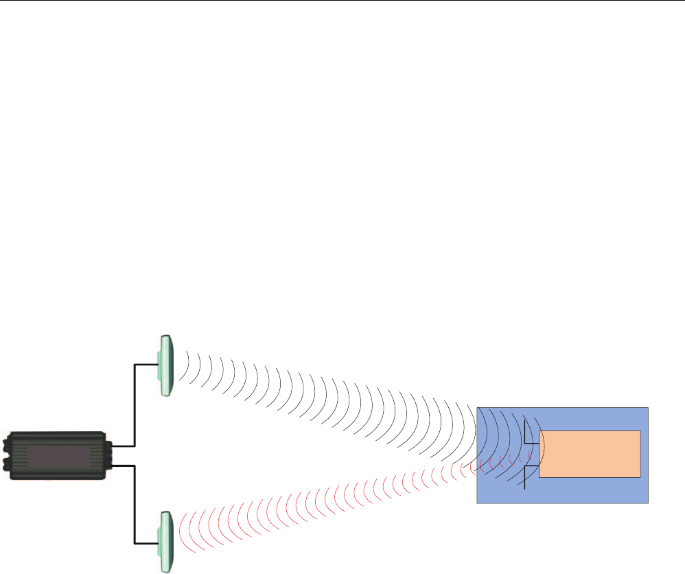
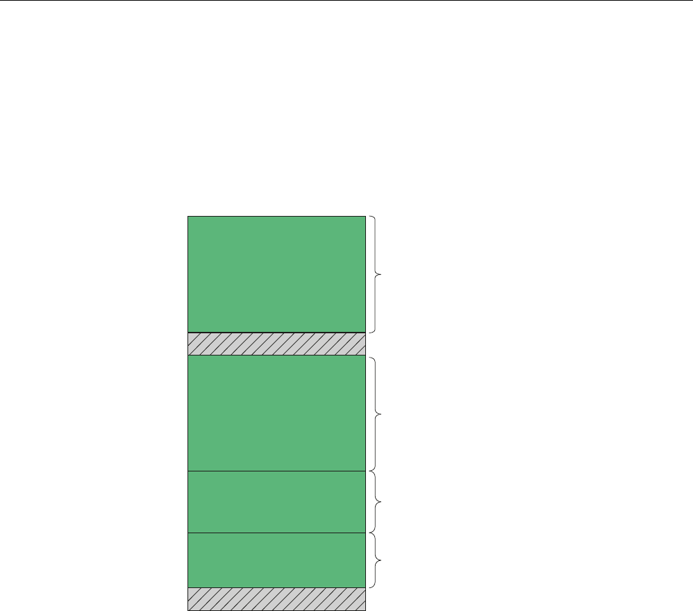
Spatial directional radiation pattern
The following schematic diagram shows the main and auxiliary fields of the RF660A antenna
in free space in the absence of reflecting/absorbing materials. Please note that the diagram
is not to scale.
The recommended working range lies within the main field that is shown in green.
Antennas
6.5 RF660A antenna
SIMATIC RF600
254 System Manual, 05/2012, J31069-D0171-U001-A13-7618
Main field (processing field)
Secondary fields
Figure 6-30 Main and auxiliary fields of the RF660A antenna
Antennas
6.5 RF660A antenna
SIMATIC RF600
System Manual, 05/2012, J31069-D0171-U001-A13-7618 255
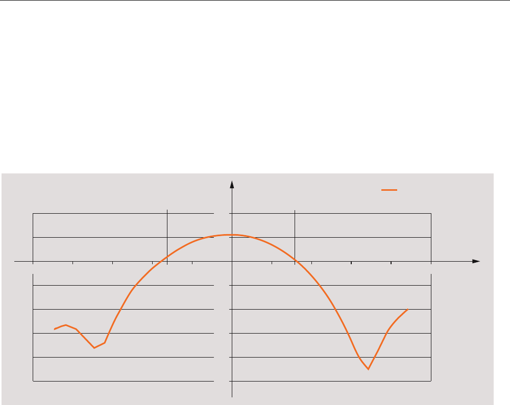
Radiation diagram (horizontal)
Europe (ETSI)
The radiation diagram is shown for horizontal alignment and for a center frequency of 865
MHz. Horizontal antenna alignment is provided when the TNC connection on the antenna
points vertically up or down.
The radiating/receiving angle of the antenna is defined by the angle between the two -3 dB
points (corresponding to half the power referred to the maximum performance at a 0° angle).
The optimum radiating/receiving angle is therefore approximately ±30 degrees.
3KL r
G%
G%G%
*DLQLQG%
$QJOH
LQGHJUHHV
Figure 6-31 Directional radiation pattern of the antenna (at 865 MHz, horizontal alignment)
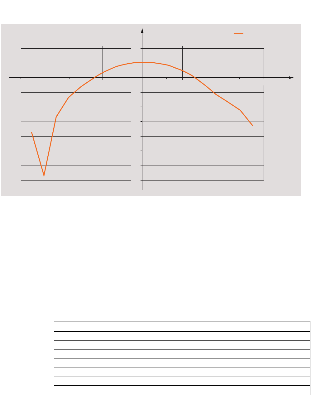
USA (FCC)
The radiation diagram is shown for horizontal alignment and for a center frequency of 915
MHz.
The radiating/receiving angle of the antenna is defined by the angle between the two -3 dB
points (corresponding to half the power referred to the maximum performance at a 0° angle).
The optimum radiating/receiving angle is therefore approximately ±35 degrees.
Antennas
6.5 RF660A antenna
SIMATIC RF600
256 System Manual, 05/2012, J31069-D0171-U001-A13-7618
3KL r
G%
G%G%
*DLQLQG%
$QJOH
LQGHJUHHV
Figure 6-32 Directional radiation pattern of the antenna (at 915 MHz, horizontal alignment)
6.5.7 Interpretation of directional radiation patterns
The following overview table will help you with the interpretation of directional radiation
patterns.
The table shows which dBi values correspond to which read/write ranges (in %): You can
read the radiated power depending on the reference angle from the directional radiation
patterns, and thus obtain information on the read/write range with this reference angle with
regard to a transponder.
The dBr values correspond to the difference between the maximum dBi value and a second
dBi value.
Deviation from maximum antenna gain [dBr] Read/write range [%]
0 100
-3 70
-6 50
-9 35
-12 25
-15 18
-18 13

Antennas
6.5 RF660A antenna
SIMATIC RF600
System Manual, 05/2012, J31069-D0171-U001-A13-7618 257
Example
As one can see from the section Antenna pattern (Page 253), the maximum antenna gain is
6 dBi. In the vertical plane, the antenna gain has dropped to approx. 3 dBi at +30°. Therefore
the dBr value is -3. The antenna range is only 50% of the maximum range at ± 30° from the
Z axis within the vertical plane.
6.5.8 Technical data
Table 6- 20 General technical specifications RF660A
Feature SIMATIC RF660A ETSI SIMATIC RF660A FCC
Dimensions (L x W x H) 313 x 313 x 80 mm
Color Pastel turquoise
PA 12 (polyamide 12) Material
Silicone-free
Frequency range 865 to 868 MHz 902 to 928 MHz
Plug connection RTNC
Max. radiated power
according to ETSI
• RF620R, RF630R:
< 1200 mW ERP
• RF640R, RF670R:
< 2000 mW ERP
-
Max. radiated power
according to CMIIT
• RF620R, RF630R:
< 1200 mW ERP
• RF640R, RF670R:
< 2000 mW ERP
-
Max. radiated power
according to FCC
- • RF620R, RF630R:
< 1600 mW EIRP
• RF640R, RF670R:
< 4000 mW EIRP
Max. power 2000 mW
Impedance 50 ohms
Antenna gain 7 dBi (5-7 dBic) 6 dBi (> 6 dBic)
VSWR (standing wave ratio) Max. 2:1
Polarization RH circular
Aperture angle for
transmitting/receiving
55° - 60° 60° - 75°
Front-to-back ratio - -
Attachment of the antenna 4 screws M4 (VESA 100 mount system)
Tightening torque
(at room temperature)
≤ 2 Nm
Antennas
6.5 RF660A antenna
SIMATIC RF600
258 System Manual, 05/2012, J31069-D0171-U001-A13-7618
Feature SIMATIC RF660A ETSI SIMATIC RF660A FCC
Ambient temperature
• Operation
• Transport and storage
• -20 °C to +70 °C
• -40 °C to +85 °C
MTBF in years 2 x 10⁹
Degree of protection according
to EN 60529
IP67
Weight, approx. 1.2 kg
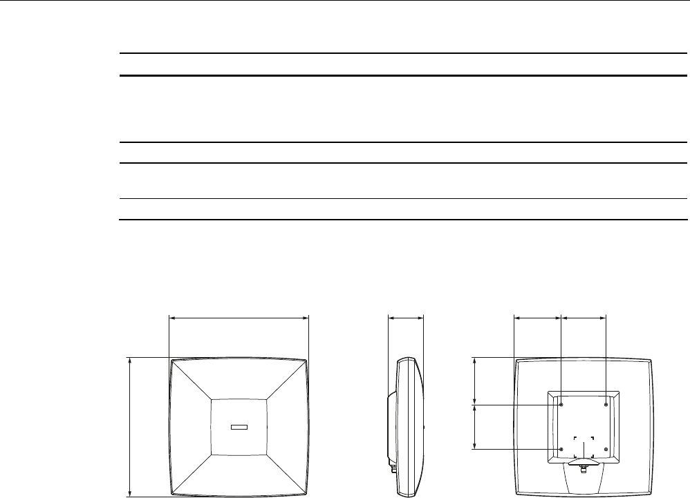
6.5.9 Dimension drawing
100
100
106,4
105,7
79,9312,9
312,9
Figure 6-33 Dimension drawing RF660A
All dimensions in mm (± 0.5 mm tolerance)
Antennas
6.5 RF660A antenna
SIMATIC RF600
System Manual, 05/2012, J31069-D0171-U001-A13-7618 259
6.5.10 Approvals & certificates
6.5.10.1 CE mark
Table 6- 21 6GT2812-0AA00
Certificate Description
Conformity in accordance with R&TTE directive
in association with the readers and accessories used
Antennas
6.5 RF660A antenna
SIMATIC RF600
260 System Manual, 05/2012, J31069-D0171-U001-A13-7618
6.5.10.2 FCC approvals
Table 6- 22 6GT2812-0AA01
Standard
Federal Communications
Commission
FCC CFR 47, Part 15 sections 15.247
Radio Frequency Interference Statement
This equipment has been tested and found to comply with the limits
for a Class B digital device, pursuant to Part 15 of the FCC Rules.
The FCC approval is granted in association with the FCC approval of
the following RF600 readers:
• FCC ID: NXW-RF600R
(for RF620R: 6GT2811-5BA00-1AA1,
RF630R: 6GT2811-4AA00-1AA1,
RF640R: 6GT2811-3BA00-1AA0,
RF670R as of FS C1: 6GT2811-0AB00-1AA0)
• FCC ID: NXW-RF630R
(for 6GT2811-4AA00-1AA0)
• FCC ID: NXW-RF670
(for RF670R as of FS A1: 6GT2811-0AB00-1AA0)
Industry Canada Radio
Standards Specifications
RSS-210 Issue 7, June 2007, Sections 2.2, A8
The approval for Industry Canada is granted in association with the
Industry Canada approval of the following RF600 readers:
• IC: 267X-RF630 (for 6GT2811-4AA00-1AA0)
• IC: 267X-RF670, RF670R FS A1 (for 6GT2811-0AB00-1AA0)
• IC: 267X-RF600R, Model RF620R-2 (for 6GT2811-5BA00-1AA1)
• IC: 267X-RF600R, Model RF630R-2 (for 6GT2811-4AA00-1AA1)
• IC: 267X-RF600R, Model RF640R (for 6GT2811-3BA00-1AA0)
• IC: 267X-RF600R, model RF670R-2 as of FS C1 (for 6GT2811-
0AB00-1AA0)
This product is UL-certified for the USA and Canada.
It meets the following safety standard(s):
UL 60950-1 - Information Technology Equipment Safety - Part 1:
General Requirements
CSA C22.2 No. 60950 -1 - Safety of Information Technology
Equipment
UL Report E 205089

Antennas
6.6 Mounting types
SIMATIC RF600
System Manual, 05/2012, J31069-D0171-U001-A13-7618 261
6.6 Mounting types
6.6.1 Overview
The following readers and antennas feature a standardized VESA 100 fixing system (4 x
M4):
● SIMATIC RF620R/RF630R/RF640R/RF670R
● SIMATIC RF640A
● SIMATIC RF660A
It is used to fix the above-mentioned antennas in place through a mounting plate or the
antenna mounting kit.
6.6.2 Ordering data
Description Machine-Readable Product Code
Antenna mounting kit 6GT2890-0AA00
Antennas
6.6 Mounting types
SIMATIC RF600
262 System Manual, 05/2012, J31069-D0171-U001-A13-7618
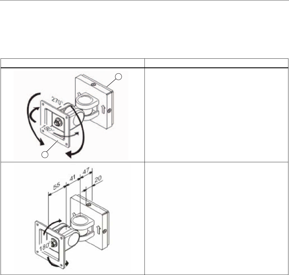
6.6.3 Mounting with antenna mounting kit
Flexible mounting is possible using the antenna mounting kit.
An antenna can then be rotated through any angle in space.
Antenna mounting kit Description
Swivel range of wall mounting
(1) Wall side
(2) Antenna side
Distances for wall mounting
Antennas
6.6 Mounting types
SIMATIC RF600
System Manual, 05/2012, J31069-D0171-U001-A13-7618 263
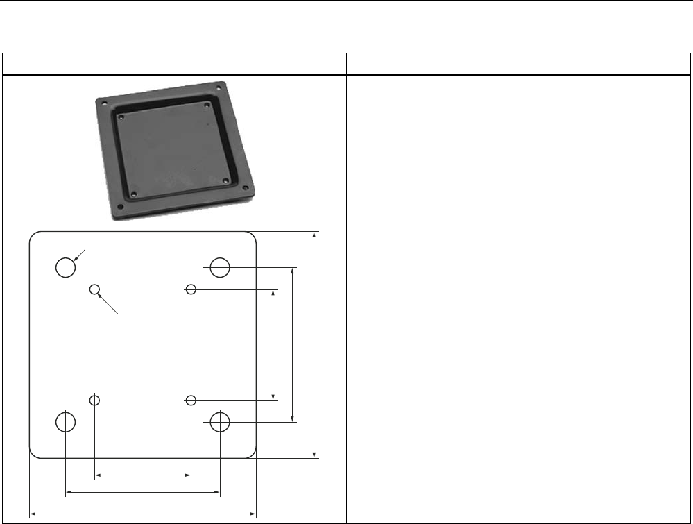
Antenna mounting kit Description
VESA adapter plate
from VESA 75 x 75
to VESA 100 x 100
The VESA adapter plate is required for fixing the antenna to
the antenna mounting kit.
;WKUHDG0
;
Hole drilling template for fixing the antenna mounting kit to
the wall

Antennas
6.6 Mounting types
SIMATIC RF600
264 System Manual, 05/2012, J31069-D0171-U001-A13-7618
SIMATIC RF600
System Manual, 05/2012, J31069-D0171-U001-A13-7618 265
Transponder/tags 7
7.1 Overview
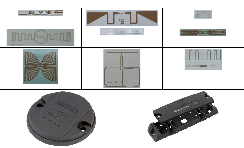
7.1.1 Tags in different sizes and types
Tags/transponders and labels are available in a variety of shapes, sizes and materials. The
pictures below show some examples of tags and labels in different designs.
Tags in different sizes and types
Transponder/tags
7.1 Overview
SIMATIC RF600
266 System Manual, 05/2012, J31069-D0171-U001-A13-7618
7.1.2 Mode of operation of transponders/tags
The tag/transponder mainly comprises a microchip with an integral memory and a dipole
antenna.
The principle of operation of a passive RFID transponder is as follows:
● Diversion of some of the high-frequency energy emitted by the reader to supply power to
the integral chip
● Commands received from reader
● Responses are transmitted to the reader antenna by modulating the reflected radio
waves (backscatter technique)
5HIOHFWHGDQGPRGXODWHG
ZDYHIURPWDJWUDQVSRQGHU
5)5
5HDGHU
$QWHQQD
$QWHQQD
0LFURFKLSZLWK
LQWHJUDWHG
PHPRU\
(OHFWURPDJQHWLFZDYHV
IURPUHDGHUDQWHQQD
7UDQVSRQGHU
$QWHQQD
Figure 7-1 Mode of operation of transponders
The transmission ranges achieved vary in accordance with the size of the tag and the
corresponding dipole antenna. In general the following rule applies: The smaller the tag and
therefore the antenna, the shorter the range.
7.1.3 Transponder classes and generations
The transponder classes are distinguished by the different communication protocols used
between the reader and transponder. Transponder classes are mostly mutually incompatible.
The following transponder classes are supported by the RF 600 system:
● EPC Global Class 1 Gen 2 with full EPC Global Profile (ISO 18000-6C)

Transponder/tags
7.1 Overview
SIMATIC RF600
System Manual, 05/2012, J31069-D0171-U001-A13-7618 267
Support for protocol types using the RF600
The definition of the transponders/tags according to ISO 18000-6 (corresponds to EPC
Global Class 1 Gen 2) refers to implementation of the air-interface protocols.
EPC Global
EPC Class Definition Programming Supported in
RF600
Class 1 Passive tags with the following minimum
features:
• EPC ID (Electronic Product Code
IDentifier)
• Tag ID
• A function which permanently
ensures that tags no longer respond.
• Optional use or suppression of tags
• Optional password-protected access
control
• Optional USER memory area.
Programming by the customer
(cannot be reprogrammed
after locking)
Yes
Class 2 Passive tags with the following
additional features (in comparison with
Class 1 tags):
• Extended tag ID,
• Extended USER memory area
• Authenticated ACCESS access
• Additional features
No
Class 3 Passive tags with the following
additional features (in comparison with
Class 2 tags):
• Source of energy that supplies
power to the tag or its sensors
• Sensors with optional data logging
No
Class 4 Active tags with the following features:
• EPC ID (Electronic Product Code
IDentifier)
• Extended tag ID
• Authenticated ACCESS access
• A source of energy
• Communication using an
autonomous transmitter
• Optional USER memory area.
• Optional sensors with or without
optional data logging
Freely programmable
No
Transponder/tags
7.1 Overview
SIMATIC RF600
268 System Manual, 05/2012, J31069-D0171-U001-A13-7618
Table 7- 1 Comparison of EPC Class 1 Gen 1 and Class 1 Gen 2
Property Class 1 Gen 1 Class 1 Gen 2 =
ISO 18000-6 C
Frequency 860-930 MHz 860-960 MHz
Memory capacity 64 or 96 bits 96-256 bits
Can be programmed on site Yes Yes
Programming written once; read many times Yes
Other Features _ Reading is faster and more reliable
than for Generation 1.
Enhanced compliance with global
standards.
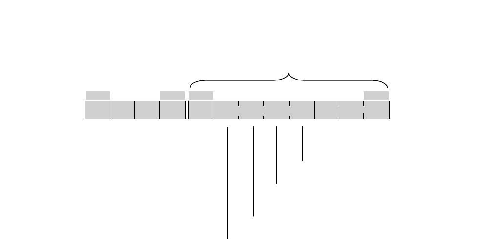
7.1.4 Electronic Product Code (EPC)
The Electronic Product Code (EPC) supports the unique identification of objects (e.g. retail
items, logistical items or transport containers). This makes extremely accurate identification
possible. In practical use, the EPC is stored on a transponder (tag) and scanned by the
reader.
There are different EPC number schemes with different data lengths. Below is the structure
of a GID-96-bit code (EPC Global Tag Data Standards V1.1 Rev. 1.27) :
+HDGHU (3&0DQDJHU 2EMHFW&ODVV 6HULDO1XPEHU
ELW ELW ELW ELW
34
● Header: This identifies the EPC identification number that follows with regard to length,
type, structure and version of the EPC
● EPC manager: This identifies the company/corporation
● Object class: Corresponds to the article number
● Serial number: Consecutive number of the article
The Siemens UHF transponders are all suitable for working with EPC and other number
schemes. Before a transponder can work with a number scheme, the relevant numbers must
first be written to the transponder.
Transponder/tags
7.1 Overview
SIMATIC RF600
System Manual, 05/2012, J31069-D0171-U001-A13-7618 269
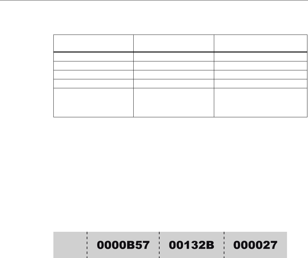
Allocation of the ECP ID by the tag manufacturer
6,0$7,&DGGUHVV
UHVHUYHG +H[VWDUWVHYHU\
GD\ZLWK[
0RQWKWR
&RQWHQWV+H[[WR[&
'D\WR
&RQWHQWV+H[[WR[)
<HDU
&RQWHQWV[[[$
7DJW \SH
&RUUHVSRQGVWR8,'ZLWK)&
6HULDOQXPEHU
0DQXIDFWXULQJFRGH
5)7 [(
5)7 [)
5)7 [
5)7 [
))
)))) ))%
06% /6%
Figure 7-2 Allocation of the EPC ID on delivery of the tag
Transponder/tags
7.1 Overview
SIMATIC RF600
270 System Manual, 05/2012, J31069-D0171-U001-A13-7618
7.1.5 SIMATIC memory configuration of the RF600 transponders and labels
SIMATIC memory configuration
The following graphic shows the structure of the virtual SIMATIC memory for the
RF620R/RF630R reader and explains the function of the individual memory areas. The
SIMATIC memory configuration is based on the 4 memory banks, as they are defined in
EPC Global.
7KH86(5PHPRU\DUHDDOZD\VEHJLQVDWDGGUHVV
DQGHQGVZLWKWKHKLJKHVWDGGUHVVRIWKHWDJ7KH
PD[LPXPVL]HRIWKH86(5PHPRU\DUHDLVE\WHV
7KH(3&PHPRU\DUHDDOZD\VVWDUWVDWWKHDGGUHVV))
7KHPD[LPXPVL]HRIWKH(3&PHPRU\DUHDLVE\WHV
7KH(3&PHPRU\DUHDFRQWDLQVWKH(3&,'DQGWKH
SURWRFROFRQWUROZRUG$FFHVVWRWKH&5&PHPRU\LVQRW
SRVVLEOH
))(OHQJWKE\WHV 3&3URWRFRO&RQWURO:RUG
2SWLRQDOPHPRU\DUHD
SDVVZRUGVRIWKHWUDQVSRQGHU
ವ )) .,//SDVVZRUG
ವ )) $&&(66SDVVZRUG
2SWLRQDOPHPRU\DUHD
7KH7,'PHPRU\DUHDFRQWDLQVPDQXIDFWXUHUVSHFLILFGDWD
5HDGRQO\VL]HFDQYDU\DFFRUGLQJWRWKHPDQXIDFWXUHU
7,'
5(6(59('
(3&
86(5
0HP%DQN
0HP%DQN
KH[
))KH[
)))KH[
))KH[
))%)KH[
))&KH[
)))KH[
0HP%DQN
0HP%DQN
)()KH[
Figure 7-3 SIMATIC memory areas of the RF600 transponders

Transponder/tags
7.1 Overview
SIMATIC RF600
System Manual, 05/2012, J31069-D0171-U001-A13-7618 271
Special memory configuration of the RF600 transponders and labels
Tags Chip type User
[hex]
EPC TID RESERVED
(passwords)
Special
Range Access KILL-PW Lock
function
RF630L
(-2AB00,
-2AB01)
Impinj
Monza 2
00 - 3F FF00-FF0B
(96 bits =
FF00-FF0F)
read/
write
FFC0-FFC7 FF80-FF87 Yes Yes
RF630L
(-2AB02)
Impinj
Monza 4QT
00 - 3F FF00-FF0B
(128 bits =
FF00-FF0F)
read/
write
FFC0-FFC9 FF80-FF87 Yes Yes
RF630L
(-2AB03)
NXP G2XM 00 - 3F FF00-FF0B
(240 bits =
FF00-FF0F)
read/
write
FFC0-FFC7 FF80-FF87 Yes Yes
RF680L NXP G2XM 00 - 3F FF00-FF0B
(240 bits =
FF00-FF0F)
read/
write
FFC0-FFC7 FF80-FF87 Yes Yes
RF610T NXP G2XM 00 - 3F FF00-FF0B
(240 bits =
FF00-FF0F)
read/
write
FFC0-FFC7 FF80-FF87 LOCKED Yes
RF620T Impinj
Monza 4QT
00 - 3F FF00-FF0B
(128 bits =
FF00-FF0F)
read/
write
FFC0-FFC9 FF80-FF87 LOCKED Yes
RF625T Impinj
Monza 4QT
00 - 3F FF00-FF0B
(128 bits =
FF00-FF0F)
read/
write
FFC0-FFC9 FF80-FF87 LOCKED Yes
RF630T NXP G2XM 00 - 3F FF00-FF0B
(240 bits =
FF00-FF0F)
read/
write
FFC0-FFC7 FF80-FF87 LOCKED Yes
RF640T NXP G2XM 00 - 3F FF00-FF0B
(240 bits =
FF00-FF0F)
read/
write
FFC0-FFC7 FF80-FF87 LOCKED Yes
RF680T NXP G2XM 00 - 3F FF00-FF0B
(240 bits =
FF00-FF0F)
read/
write
FFC0-FFC7 FF80-FF87 LOCKED Yes
Note
Default EPC ID
When an RF610T-RF680T transponder is supplied, a 12 byte long identifier is assigned by
the manufacturer as the EPC ID according to a number scheme (see "Assignment of the
ECP ID by the manufacturer").
Transponder/tags
7.1 Overview
SIMATIC RF600
272 System Manual, 05/2012, J31069-D0171-U001-A13-7618
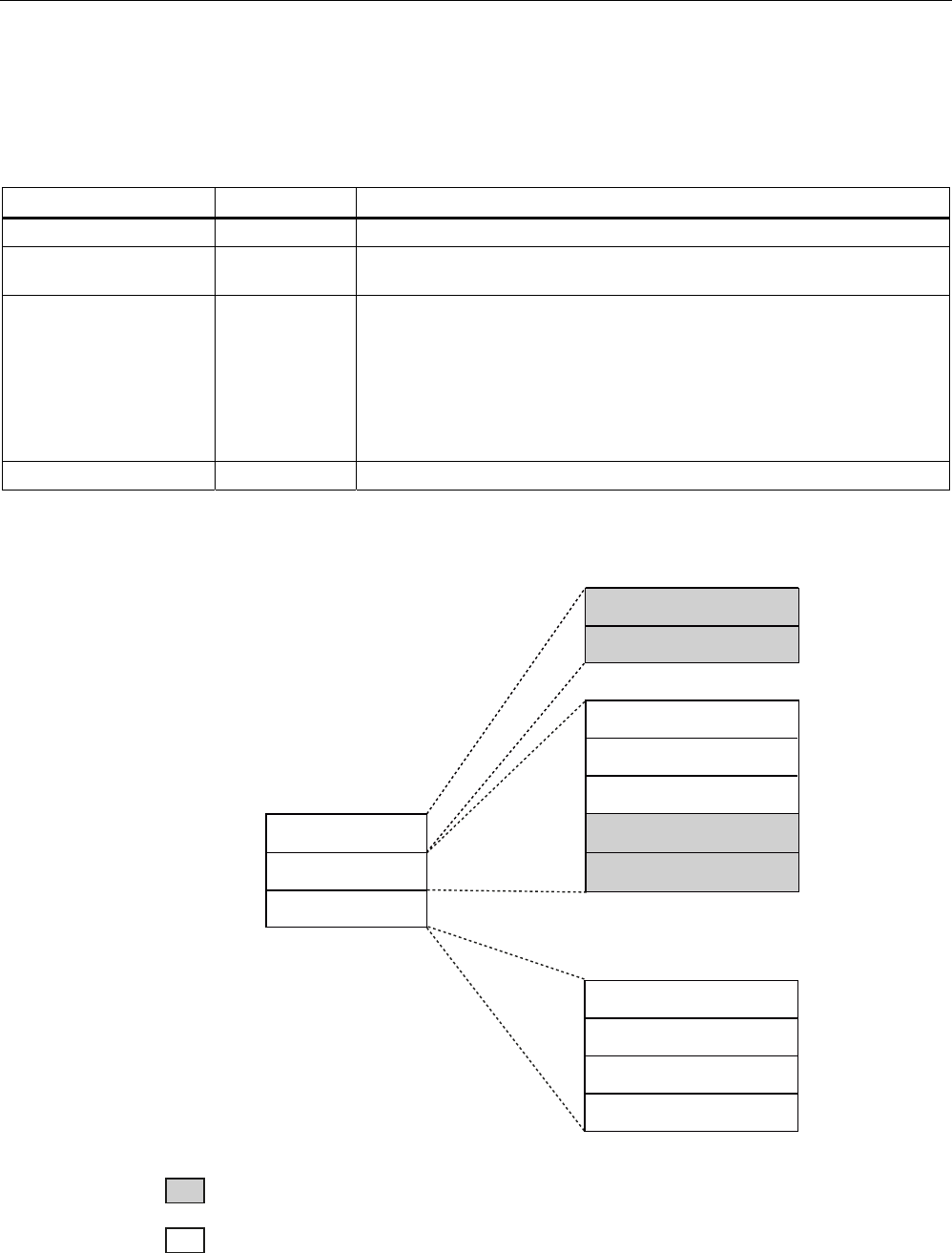
Memory map of the ISO 18000-6C Monza 2 chip according to EPC
The memory of the ISO 18000-6C Monza 2 chip is divided logically into four different
memory banks:
Memory bank (decimal) Memory type Description
MemBank 112 USER User-writable USER memory area
MemBank 102 TID Is defined by the manufacturer, contains the class identifier and serial
number of a transponder.
MemBank 012 EPC Contains the EPC UID, the protocol and the CRC of a transponder.
You can write to the EPC memory area. In the delivery condition, the
memory contents can have the following states:
• empty
• containing the same data
• containing different data
MemBank 002 RESERVED Contains the access and kill password.
The graphic below illustrates the exact memory utilization. Each box in the right part of the
graphic represents one word (16 bit) in the memory.
0HP%DQN
0HP%DQN
0HP%DQN
7,'
(3&
5(6(59('
06% /6%
7,'>@
7,'>@
K
K
K
K
K
K
K
K
K
K
06% /6%
(3&>@
3URWRFRO&RQWURO>@
&5&>@
(3&>@
)
K
)
K
)
K
)
K
)
K
)
K
06% /6%
)
K
)
K
)
K
)
K
$FFHVV3DVVZ>@
$FFHVV3DVVZ>@
.LOO3DVVZ>@
.LOO3DVVZ>@
Color Mode of access by RF600 reader
Read
Write / read

Transponder/tags
7.1 Overview
SIMATIC RF600
System Manual, 05/2012, J31069-D0171-U001-A13-7618 273
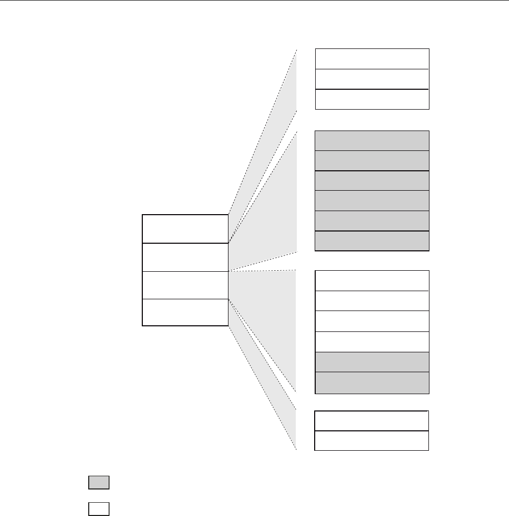
Memory map of the ISO 18000-6C Monza 4QT chip according to EPC
The memory of the ISO 18000-6C Monza 4QT chip is divided logically into four different
memory banks:
Memory bank (decimal) Memory type Description
MemBank 112 USER User-writable USER memory area
MemBank 102 TID Is defined by the manufacturer, contains the class identifier and serial
number of a transponder.
MemBank 012 EPC Contains the EPC data, the protocol information and the CRC data of a
transponder.
You can write to the EPC memory area. In the delivery condition, the
memory contents can have the following states:
• containing the same data
• containing different data
MemBank 002 RESERVED Contains the access and kill password.
The graphic below illustrates the exact memory utilization. Each box in the right part of the
graphic represents one word (16 bit) in the memory.
Transponder/tags
7.1 Overview
SIMATIC RF600
274 System Manual, 05/2012, J31069-D0171-U001-A13-7618
K
K
06% /6%
)
K
)
K
$FFHVV3DVVZ>@
$FFHVV3DVVZ>@
0HP%DQN
0HP%DQN
0HP%DQN
0HP%DQN
7,'
86(5
(3&
5(6(59('
06% /6%
7,'>@
7,'>@
K
K
K
K
K
06% /6%
(3&>@
3URWRFRO&RQWURO>@
&5&>@
)
K
)
K
)
K
)
K
K
06% /6%
86(5>@
86(5>@ ))
K
)
K
)
K
)
K
7,'6HULDOQXPEHU>@
7,'6HULDOQXPEHU>@
7,'6HULDOQXPEHU>@
([WHQGHG7,'+HDGHU>@
K
)
K
K
)
K
K
)
K
K
)
K
K
(3&>@ )
K
K
(3&>@ )
K
Color Mode of access by RF600 reader
Read
Write / read

Transponder/tags
7.1 Overview
SIMATIC RF600
System Manual, 05/2012, J31069-D0171-U001-A13-7618 275
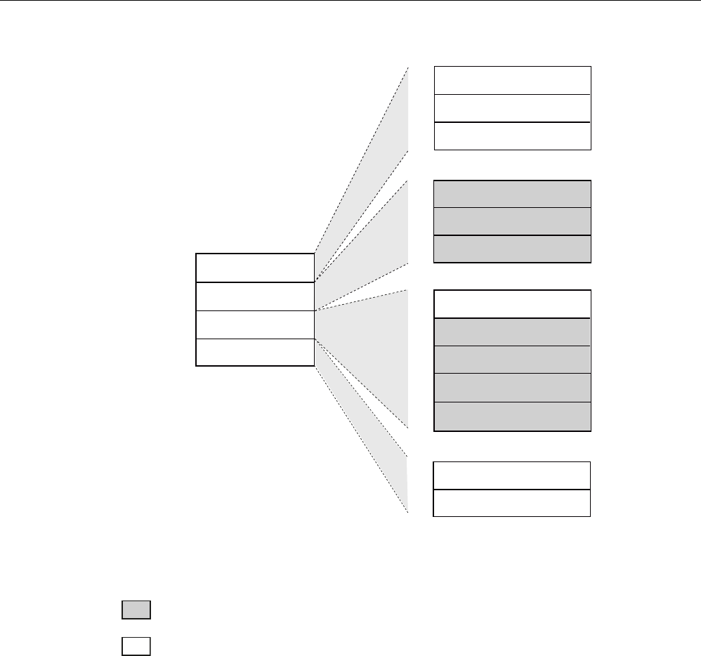
Memory map of the ISO 18000-6C G2XM chip according to EPC
The memory of the ISO 18000-6C G2XM chip is divided logically into four different memory
banks:
Memory bank (decimal) Memory type Description
MemBank 112 USER User-writable USER memory area
MemBank 102 TID Is defined by the manufacturer, contains the class identifier and serial
number of a transponder.
MemBank 012 EPC Contains the EPC data, the protocol information and the CRC data of a
transponder.
You can write to the EPC memory area. In the delivery condition, the
memory contents can have the following states:
• containing the same data
• containing different data
MemBank 002 RESERVED Contains the access and kill password.
The graphic below illustrates the exact memory utilization. Each box in the right part of the
graphic represents one word (16 bits) in the memory.
Transponder/tags
7.1 Overview
SIMATIC RF600
276 System Manual, 05/2012, J31069-D0171-U001-A13-7618
K
K
06% /6%
)K
)K
$FFHVV3DVVZ>@
$FFHVV3DVVZ>@
0HP%DQN
0HP%DQN
0HP%DQN
0HP%DQN
7,'
86(5
(3&
5(6(59('
06% /6%
7,'>@
6HULDOQXPEHU>@
7,'>@
K
K
K
K
K
K
06% /6%
(3&>@
3URWRFRO&RQWURO>@
&5&>@
(3&>@
)K
K)
K
)K
)K
)K
)K
K
06% /6%
86(5>@
86(5>@ ))K
)K
)K
)K
Color Mode of access by RF600 reader
Read
Write / read
Parameterization
Which parameter assignment options available to you for which reader of the RF600 family
is outlined in the section "Overview of parameterization of RF600 reader (Page 377)".
Detailed information for parameterization as well as examples for describing and reading
specific memory areas can be found in the referenced chapters of the documentation.
Transponder/tags
7.2 SIMATIC RF630L Smartlabel
SIMATIC RF600
System Manual, 05/2012, J31069-D0171-U001-A13-7618 277
7.2 SIMATIC RF630L Smartlabel
7.2.1 Features
SIMATIC RF630L smart labels are passive, maintenance-free data carriers based on
UHF Class 1 Gen2 technology that are used to store the "Electronic Product Code" (EPC).
Smart labels offer numerous possible uses for a wide range of applications and support
efficient logistics throughout the process chain.
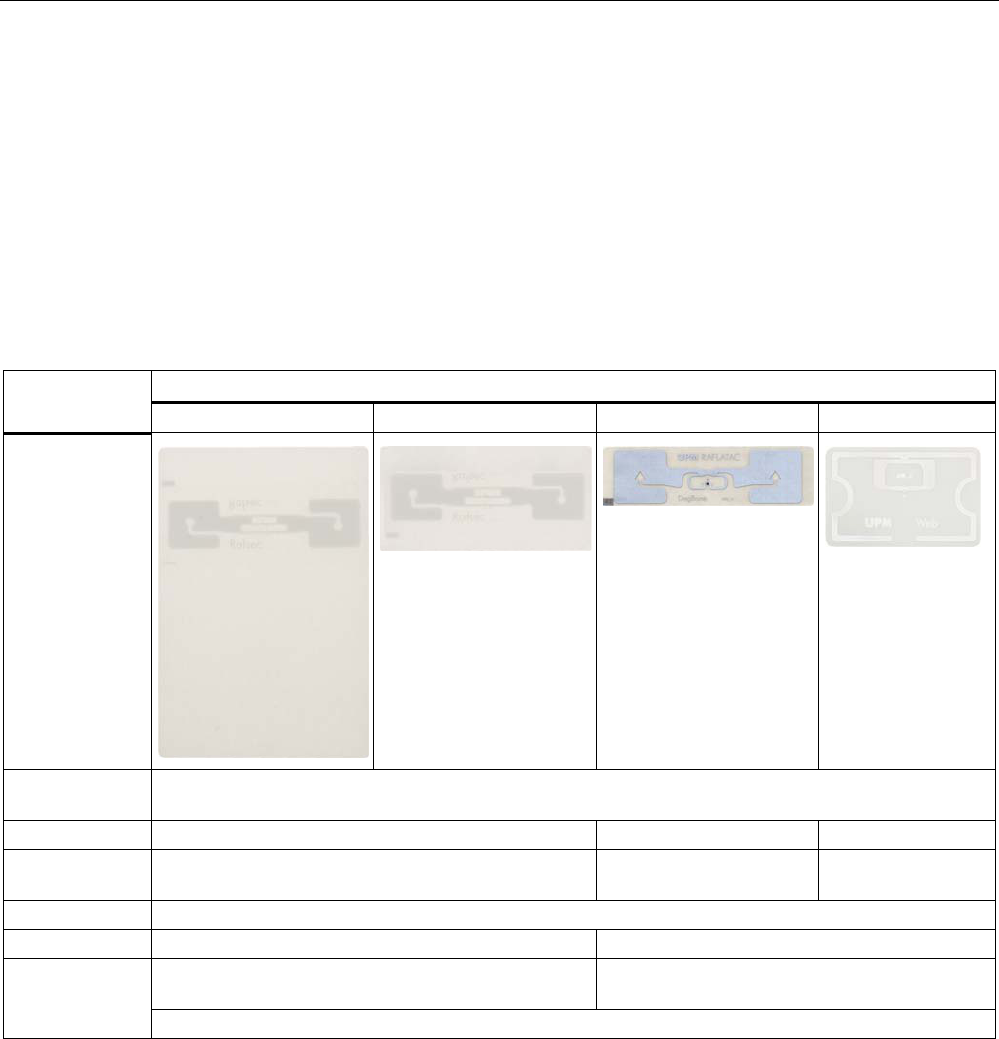
SIMATIC RF630L transponder
6GT2810-2AB00 6GT2810-2AB01 6GT2810-2AB02-0AX0 6GT2810-2AB03
Design
Application Simple identification such as barcode replacement or supplementation, through warehouse and
distribution logistics, right up to product identification.
Memory EPC 96 bits EPC 96/128 bits EPC 96/240 bits
Additional user
memory
No 64 bytes 64 bytes
Write range 0.2 m to 5 m
Reading range 0.2 m to 8 m 0.2 m to 5 m
Self-adhesive paper labels, for example for attaching
to packaging units, paper or cartons
Self-adhesive plastic labels, for example for
attaching to packaging units, paper or cartons
Mounting
Not suitable for fixing straight onto metal or onto liquid containers
Transponder/tags
7.2 SIMATIC RF630L Smartlabel
SIMATIC RF600
278 System Manual, 05/2012, J31069-D0171-U001-A13-7618
7.2.2 Ordering data
RF630L transponder Order number Type of delivery
RF630L transponder,
smart label
101.6 mm x 152.4 mm (4" x 6")
6GT2810-2AB00 Minimum order amount 1600 items
(800 on one roll)
RF630L transponder,
smart label 101.6 mm x 50.8 mm (4" x 2")
6GT2810-2AB01 Minimum order amount 1000 items
(1000 on one roll)
RF630L transponder,
smart label 97 mm x 27 mm
6GT2810-2AB02-
0AX0
Minimum order amount 5000 items
(5000 on one roll)
RF630L transponder,
smart label 54 mm x 34 mm
6GT2810-2AB03 Minimum order amount 2000 items
(2000 on one roll)
7.2.3 Minimum spacing between labels
D
E
Figure 7-4 Minimum spacing between labels
The specified minimum spacing applies for the SIMATIC RF630L smart labels with the
following order numbers:
● 6GT2810-2AB00
● 6GT2810-2AB01
● 6GT2810-2AB02-0AX0
● 6GT2810-2AB03
Table 7- 2 Minimum spacing
Name Minimum spacing
a 50 mm
b 50 mm

Transponder/tags
7.2 SIMATIC RF630L Smartlabel
SIMATIC RF600
System Manual, 05/2012, J31069-D0171-U001-A13-7618 279
Please note that smart labels can also be attached one above the other. The spacing
between the labels attached one above the other depends on the damping characteristics of
the carrier material.
7.2.4 Memory configuration of the smart label
The memory configuration of the smart label is described in the section SIMATIC memory
configuration of the RF600 transponders and labels (Page 270).
7.2.5 Technical data
Table 7- 3 Mechanical data
6GT2810-2AB00 6GT2810-2AB01 6GT2810-2AB02-0AX0 6GT2810-2AB03
Dimensions (L x W) 101.6 mm x 152.4 mm
(ca. 4" x 6")
101.6 mm x 50.8 mm
(ca. 4" x 2")
97 mm x 27 mm 54 mm x 34 mm
Design Paper with integrated antenna Plastic with integrated antenna
Label type Paper label Inlay
Antenna material Aluminum
Static pressure 10 N/mm2
Material surface Paper Plastic PET
Type of antenna Shortened dipole
Color white Transparent
Printing Can be printed using heat transfer technique
Mounting Single-sided adhesive (self-adhesive label).
Single-sided adhesive (self-adhesive inlay).
Degree of protection None, the label must be protected against
humidity.
IP65
Weight Approx. 3 g Approx. 2 g Approx. 1 g

Transponder/tags
7.2 SIMATIC RF630L Smartlabel
SIMATIC RF600
280 System Manual, 05/2012, J31069-D0171-U001-A13-7618
Table 7- 4 Electrical data
6GT2810-2AB00 6GT2810-2AB01 6GT2810-2AB02-0AX0 6GT2810-2AB03
Air interface ISO 18 000-6 Type C
Polarization type Linear
Polarization direction The polarization
direction is parallel
with the short side of
the paper label
The polarization
direction is parallel
with the long side of
the paper label
The polarization direction is parallel with the
long side of the inlay
Frequency range 860 to 960 MHz
Typical
read distance
• Paper/cardboard
• Plastic film
• Plastic (boxes,
surface resistance
> 10 MΩ
• Wood (dry, < 30 %
residual humidity)
• Glass
• 0.2 m to 8 m
• 0.2 m to 8 m
• 0.2 m to 4 m
• 0.2 m to 4 m
• 0.2 m to 4 m
• 0.2 m to 5 m
• 0.2 m to 5 m
• 0.2 m to 3 m
• 0.2 m to 3 m
• 0.2 m to 3 m
Typical
write distance
• Paper/cardboard
• Plastic film
• Plastic (boxes,
surface resistance
> 10 MΩ
• Wood (dry, < 30 %
residual humidity)
• Glass
• 0.2 m to 5 m
• 0.2 m to 5 m
• 0.2 m to 2.5 m
• 0.2 m to 2.5 m
• 0.2 m to 2.5 m
• 0.2 m to 3 m
• 0.2 m to 3 m
• 0.2 m to 1 m
• 0.2 m to 1 m
• 0.2 m to 1 m
Minimum spacing
between labels
• Vertically
• Horizontally
• 50 mm
• 100 mm
Energy source Field energy via antenna, without battery
Multi-tag capability Yes

Transponder/tags
7.2 SIMATIC RF630L Smartlabel
SIMATIC RF600
System Manual, 05/2012, J31069-D0171-U001-A13-7618 281
Table 7- 5 Memory specifications
6GT2810-2AB00 6GT2810-2AB01 6GT2810-2AB02-0AX0 6GT2810-2AB03
Type EPC Class 1 Gen2
Memory organization EPC 96 bits EPC 96/128 bits EPC 96/240 bits
Additional user memory No 64 bytes 64 bytes
Listing ISO 18000-6C
Data retention at
+25 °C
10 years
Read cycles Unlimited
Write cycles 100,000
Anti collision Approx. 100 labels/sec
Table 7- 6 Environmental conditions
6GT2810-2AB00 6GT2810-2AB01 6GT2810-2AB02-0AX0 6GT2810-2AB03
Temperature range
during operation
-40 °C … 65 °C, up to 80 °C (200 cycles)
Temperature range
during storage
The label should be stored in the range of +15°C and +25°C at a humidity of 40% to 60%.
Storage duration Two years, determined by the shelf life of the adhesive
Torsion and bending
load
Partially permissible
Distance from metal Not suitable for fixing straight onto metal
Table 7- 7 Identification
6GT2810-2AB00 6GT2810-2AB01 6GT2810-2AB02-0AX0 6GT2810-2AB03
CE CE approval to R&TTE
FCC Passive labels or transponders comply with the valid regulations; certification is not required.
Transponder/tags
7.2 SIMATIC RF630L Smartlabel
SIMATIC RF600
282 System Manual, 05/2012, J31069-D0171-U001-A13-7618
7.2.6 Dimension drawings
PP
PP
PP
PP
PP
PP
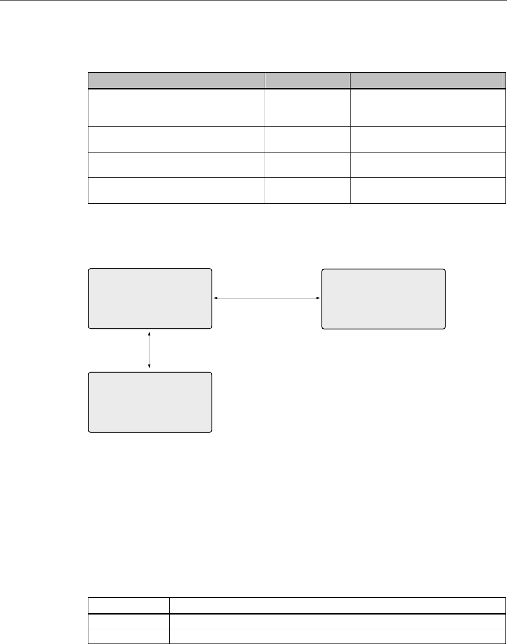
Figure 7-5 SIMATIC RF630L 6GT2810-2AB00 dimension drawing
PP
PP
PP
PP
PP
PP
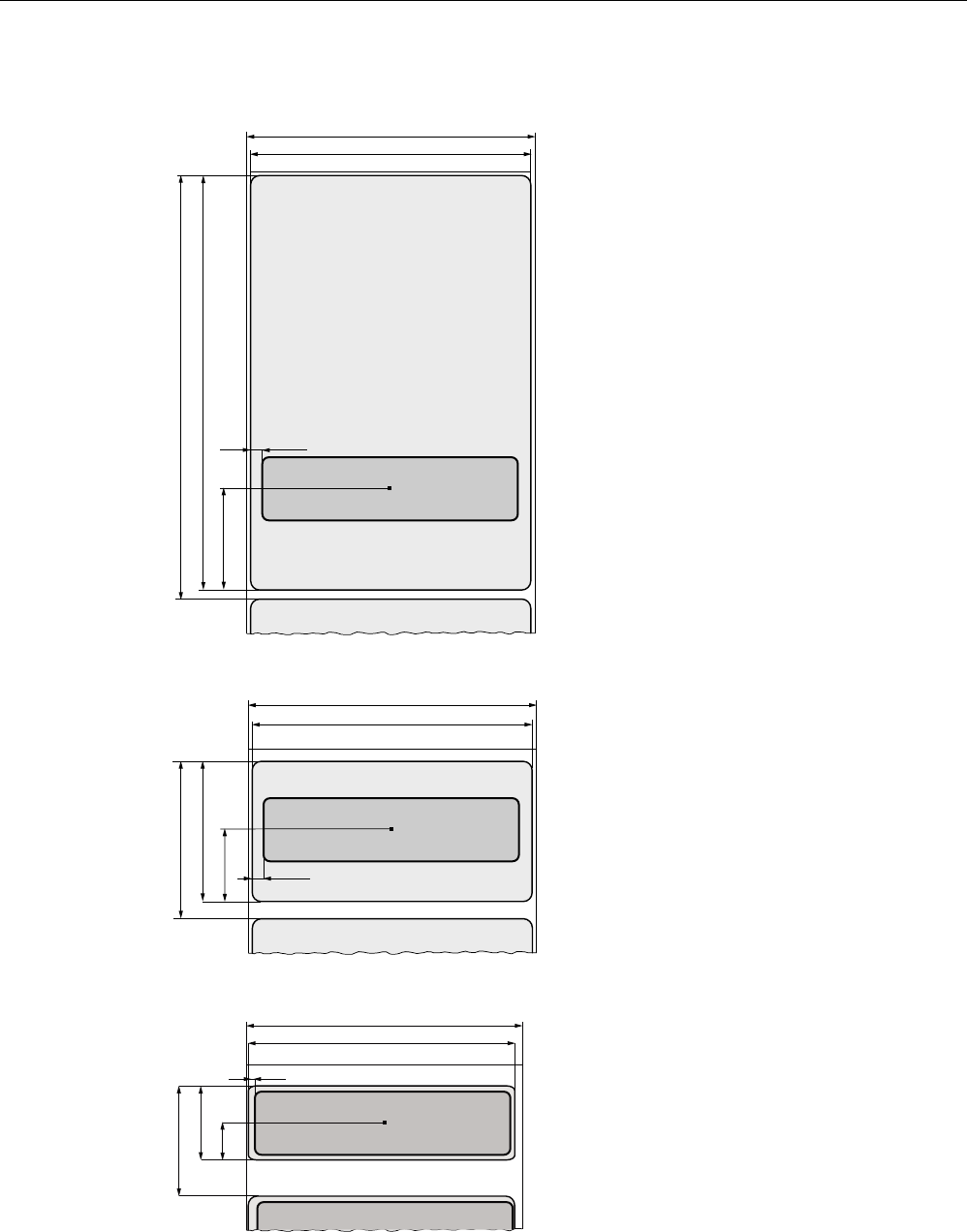
Figure 7-6 SIMATIC RF630L 6GT2810-2AB01 dimension drawing
PP
PP
PP
PP
PP
PP
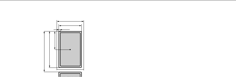
Figure 7-7 Dimension drawing SIMATIC RF630L 6GT2810-2AB02-0AX0
Transponder/tags
7.2 SIMATIC RF630L Smartlabel
SIMATIC RF600
System Manual, 05/2012, J31069-D0171-U001-A13-7618 283
PP
PP
PP
PP
PP
PP
Figure 7-8 SIMATIC RF630L 6GT2810-2AB03 dimension drawing
Transponder/tags
7.3 SIMATIC RF680L Smartlabel
SIMATIC RF600
284 System Manual, 05/2012, J31069-D0171-U001-A13-7618
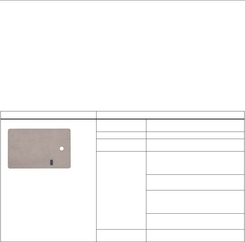
7.3 SIMATIC RF680L Smartlabel
7.3.1 Features
The SIMATIC RF680L Smartlabel is passive and maintenance-free. It functions based on the
UHF Class 1 Gen 2 technology and is used for saving the electronic product code (EPC) of
96 bits/240 bits. The label also has a 512 bit user memory.
The SIMATIC RF680L is a heat-resistant Smartlabel with a limited service life. Its target use
is the direct identification of objects in high-temperature applications.
Thanks to its antenna geometry, the transponder can be read from any direction. However,
the range is reduced if it is not aligned in parallel with the antenna.
SIMATIC RF680L Smartlabel Features
Application Production logistics applications subject to high
temperatures
Air interface according to ISO°18000-6C
Memory EPC 96 bit/240 bit
Add-on-memory 64 bytes
Up to 4 m1) in connection with:
• RF640R/RF670R reader and
• RF660A antennas
Up to 3.2 m1) in connection with:
• RF640R with integrated antenna
Up to 3 m1) in connection with:
• RF620R/630R reader and
• RF660A antenna
Reading / writing range
Up to 2 m1) in connection with:
• RF620R with integrated antenna
Mounting Via a hole on the narrow side. Can also be
glued by customer.
1) Depending on the environment
Transponder/tags
7.3 SIMATIC RF680L Smartlabel
SIMATIC RF600
System Manual, 05/2012, J31069-D0171-U001-A13-7618 285
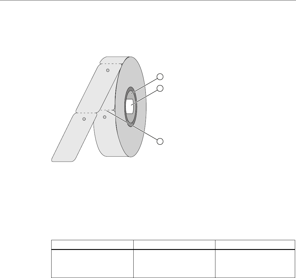
7.3.2 Delivery format
The SIMATIC RF680L is supplied on a roll. One roll always contains 1000 Smartlabels. You
can tear off the Smartlabel from the roll at the perforation.
① Cardboard tube, inner dia 76 mm
② Roll label
③ Perforation
Figure 7-9 SIMATIC RF680L roll
7.3.3 Ordering data
Ordering data Order no. Delivery format
SIMATIC RF680L
• Smartlabels 54 x 89 mm
• heat-resistant
6GT2810-2AG80 1,000 units on a roll
Transponder/tags
7.3 SIMATIC RF680L Smartlabel
SIMATIC RF600
286 System Manual, 05/2012, J31069-D0171-U001-A13-7618
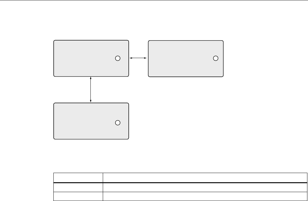
7.3.4 Minimum spacing between labels
D
E
Figure 7-10 Minimum spacing between labels
Table 7- 8 Minimum spacing
Minimum spacing
a 20 mm
b 50 mm
7.3.5 Memory configuration of the smart label
The memory configuration of the smart label is described in the section SIMATIC memory
configuration of the RF600 transponders and labels (Page 270).
Transponder/tags
7.3 SIMATIC RF680L Smartlabel
SIMATIC RF600
System Manual, 05/2012, J31069-D0171-U001-A13-7618 287
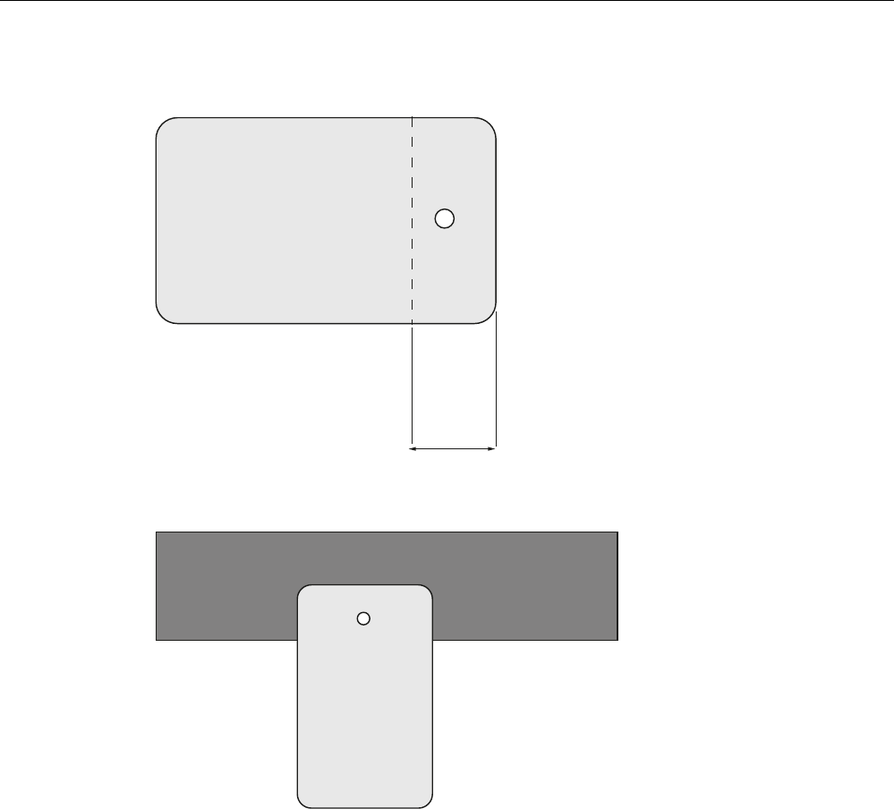
7.3.6 Mounting on metal
PP
Figure 7-11 Metal mounting surface
0HWDOFDUULHU
5)/
Figure 7-12 Mounting on metal

Transponder/tags
7.3 SIMATIC RF680L Smartlabel
SIMATIC RF600
288 System Manual, 05/2012, J31069-D0171-U001-A13-7618
7.3.7 Technical data
7.3.7.1 Mechanical data
Feature Description
Dimensions (L x W) 156 mm x 40 mm
Thickness of the label 0.4 mm (±25% incl.. chip)
Design Synthetic paper
Antenna material Aluminum
Static pressure 10 N/mm2
Silicone-free Yes
Type of antenna Shortened dipole
Color beige
Printing Yes, customized
Mounting Via a hole on the narrow side. Can also be glued by customer.
Weight Approx. 3 g
7.3.7.2 Electrical data
Feature Description
Air interface According to ISO 18 000-6 C
Polarization type Linear
Polarization direction The polarization direction is parallel with the long side of the inlay
Frequency range Europe 865…868 MHz
/ USA 902…928 MHz
RF640R/RF670R RF640R 2) RF620R/RF630R RF620R 2) Reading range 1)
Up to 4 m Up to 3.2 m Up to 3 m Up to 2 m
RF640R/RF670R RF640R 2) RF620R/RF630R RF620R 2) Writing range 1)
Up to 3 m Up to 2.4 m Up to 1.8 m Up to 0.7 m
Minimum spacing between labels
• Vertically
• Horizontally
• 50 mm
• 20 mm
Energy source Field energy via antenna, without battery
Multi-tag capability Yes
1) Depending on the environment
2) internal antenna
Transponder/tags
7.3 SIMATIC RF680L Smartlabel
SIMATIC RF600
System Manual, 05/2012, J31069-D0171-U001-A13-7618 289
7.3.7.3 Memory specifications
Property Description
Type EPC Class 1 Gen 2
EPC code 96 bits/240 bits
User memory 64 bytes
TID 64 bits
Memory organization
Reserved (passwords) 64 bits
Protocol ISO 18000-6C
Data retention time 10 years
Read cycles Unlimited
Write cycles Minimum at +22 °C 100 000
7.3.7.4 Environmental conditions
Property Description
Temperature range during operation -25 °C … +85 °C (permanent)
+200 °C up to six hours
+220 °C up to one hour
+230 °C for a short time
Temperature range during storage -40 °C … +85 °C
Torsion and bending load Partially permissible
Distance from metal Whole surface not suitable for fixing straight
onto metal (see chapter Mounting on metal
(Page 287))
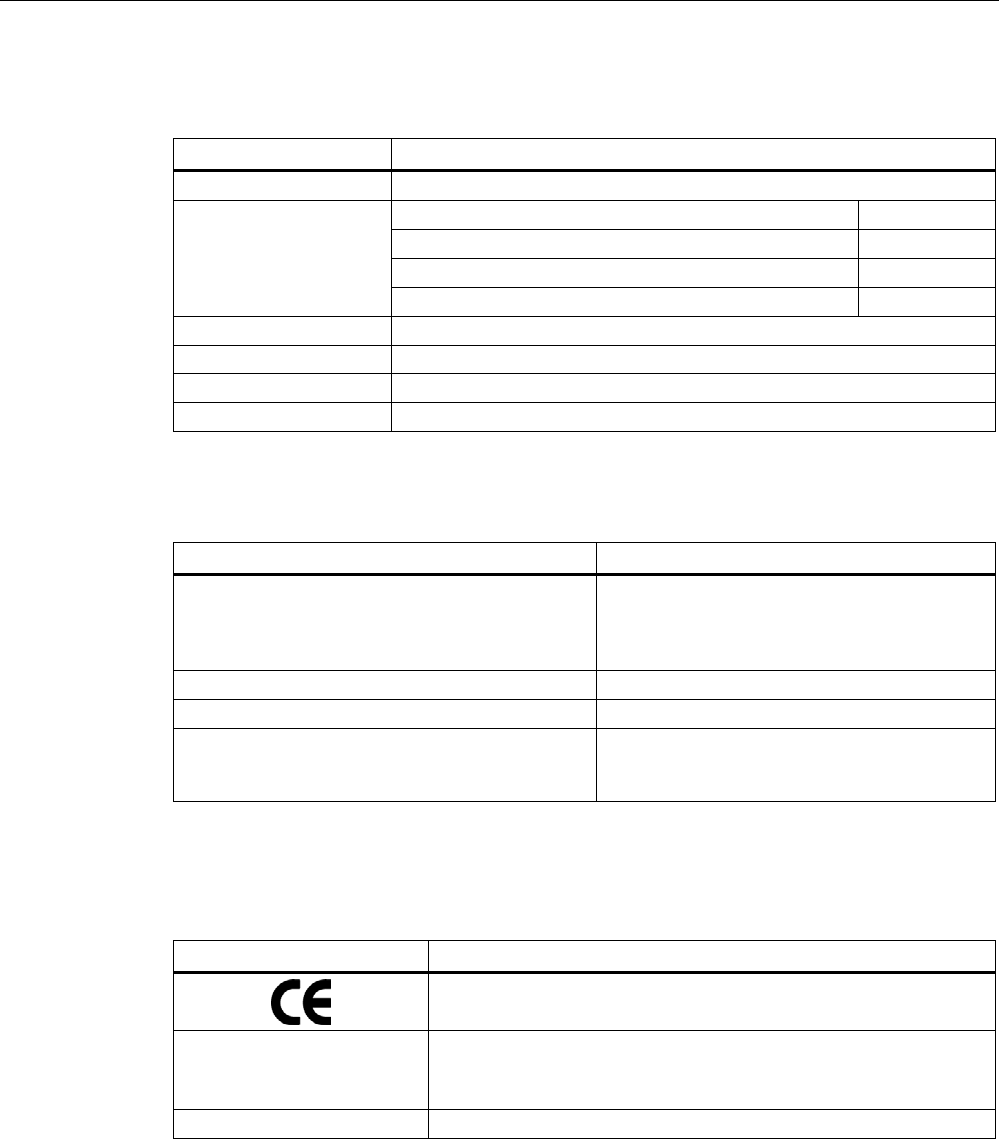
7.3.8 Certificates and approvals
Certificate Description
Conformity with R&TTE directive
FCC
Federal Communications
Commission
Passive labels and transponders comply with the valid regulations;
certification is not required.
RoHS Compliant according to EU Directive 2002/95/EC
Transponder/tags
7.3 SIMATIC RF680L Smartlabel
SIMATIC RF600
290 System Manual, 05/2012, J31069-D0171-U001-A13-7618
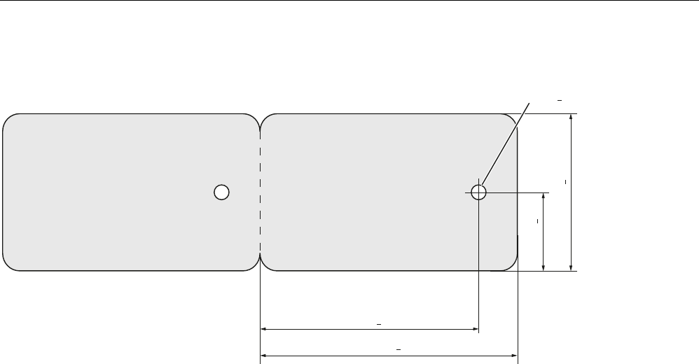
7.3.9 Dimension drawing
º
Figure 7-13 SIMATIC RF680L
Transponder/tags
7.4 SIMATIC RF610T
SIMATIC RF600
System Manual, 05/2012, J31069-D0171-U001-A13-7618 291
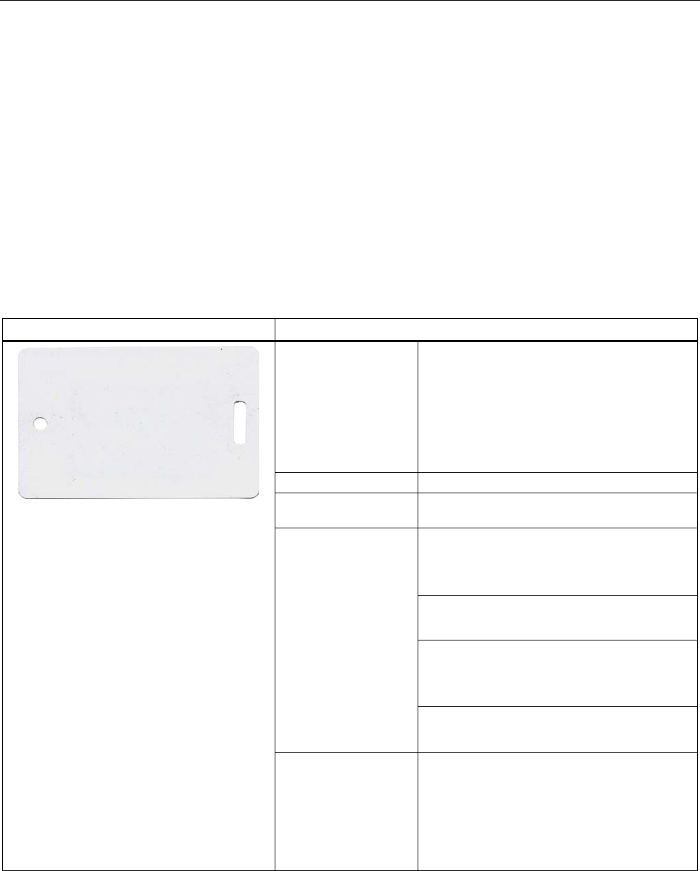
7.4 SIMATIC RF610T
7.4.1 Features
The SIMATIC RF610T is passive and maintenance-free. It functions based on the
UHF Class 1 Gen 2 technology and is used for saving the electronic product code (EPC) of
96 bits/240 bits. The label also has a 512 bit user memory.
The SIMATIC RF610T offers a host of possible uses for a wide range of applications and
supports efficient logistics throughout the entire process chain.
Thanks to its antenna geometry, the transponder can be read from any direction. However,
the range is reduced if it is not aligned in parallel with the antenna.
SIMATIC RF610T Features
Application • Simple identification, such as barcode
replacement or barcode supplement
• Warehouse and distribution logistics
• Product identification
For the Food & Beverage sector, a special
version can be supplied on request that is
certified for use in contact with food.
Air interface according to ISO°18000-6C
Memory EPC 96 bit/240 bit
Add-on-memory 64 bytes
Typically 5 m1) in connection with:
• RF640R/RF670R reader and
• RF660A antennas
Typically 3.2 m1) in conjunction with:
• RF640R with integrated antenna
Typically 3 m1) in connection with:
• RF620R/RF630R reader and
• RF660A antenna
Reading / writing range
Typically 2 m1) in connection with:
• RF620R with integrated antenna
6,0$7,&5)7*7%%$6$
s
Mounting • Suspended by means of cable ties, or
similar
• Can also be fixed with screws or glued by
customer.
• Not suitable for mounting straight onto
metal.
1) Depending on the environment
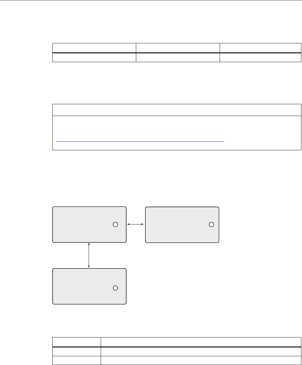
Transponder/tags
7.4 SIMATIC RF610T
SIMATIC RF600
292 System Manual, 05/2012, J31069-D0171-U001-A13-7618
7.4.2 Ordering data
Ordering data Order no. Type of delivery
SIMATIC RF610T 6GT2810-2BB80 Min. order quantity 500 units
7.4.3 Safety instructions for the device/system
NOTICE
This device/system may only be used for the applications described in the catalog and the
technical documentation "System manual MOBY D, RF200, RF300, RF600
(http://support.automation.siemens.com/WW/view/en/10805817) and only in combination
with third-party devices and components recommended and/or approved by Siemens.
7.4.4 Minimum spacing between labels
D
E
Figure 7-14 Minimum spacing between labels
Table 7- 9 Minimum spacing
Minimum spacing
a 20 mm
b 50 mm

Transponder/tags
7.4 SIMATIC RF610T
SIMATIC RF600
System Manual, 05/2012, J31069-D0171-U001-A13-7618 293
7.4.5 Memory configuration of the transponder
The memory configuration of the transponder is described in the section SIMATIC memory
configuration of the RF600 transponders and labels (Page 270).
7.4.6 Technical data
7.4.6.1 Mechanical data
Feature Description
Dimensions (L x W x H) 86 mm x 54 mm x 0.4 mm
Design PVC (polyvinyl chloride)
Antenna material Aluminum
Static pressure 10 N/m2
Type of antenna Shortened dipole
Color white
Printing Can be printed using heat transfer technique
Mounting • Suspended by means of cable ties, or similar
• Can also be fixed with screws or glued by customer.
• Not suitable for mounting straight onto metal.
Weight Approx. 3 g
7.4.6.2 Electrical data
Feature Description
Air interface According to ISO 18 000-6 C
Polarization type Linear
Polarization direction The polarization direction is parallel with the long side of the inlay
Frequency range Europe 865…868 MHz
/ USA 902…928 MHz
Reading range
typical
RF640R/RF670R/
with RF660A
RF640R RF620R/RF630R
with RF660A
RF620R
Paper/cardboard 0.2 m ... 5.0 m 0.2 m to 4.5 m 0.2 m ... 3.0 m 0.2 m ... 2.0 m
Plastic film 0.2 m ... 5.0 m 0.2 m to 4.5 m 0.2 m ... 3.0 m 0.2 m ... 2.0 m
Plastic 0.2 m ... 3.0 m 0.2 m to 2.7 m 0.2 m ... 2.0 m 0.2 m ... 1.5 m
Wood 0.2 m ... 3.0 m 0.2 m to 2.7 m 0.2 m ... 2.0 m 0.2 m ... 1.5 m
Glass 0.2 m ... 3.0 m 0.2 m to 2.7 m 0.2 m ... 2.0 m 0.2 m ... 1.5 m
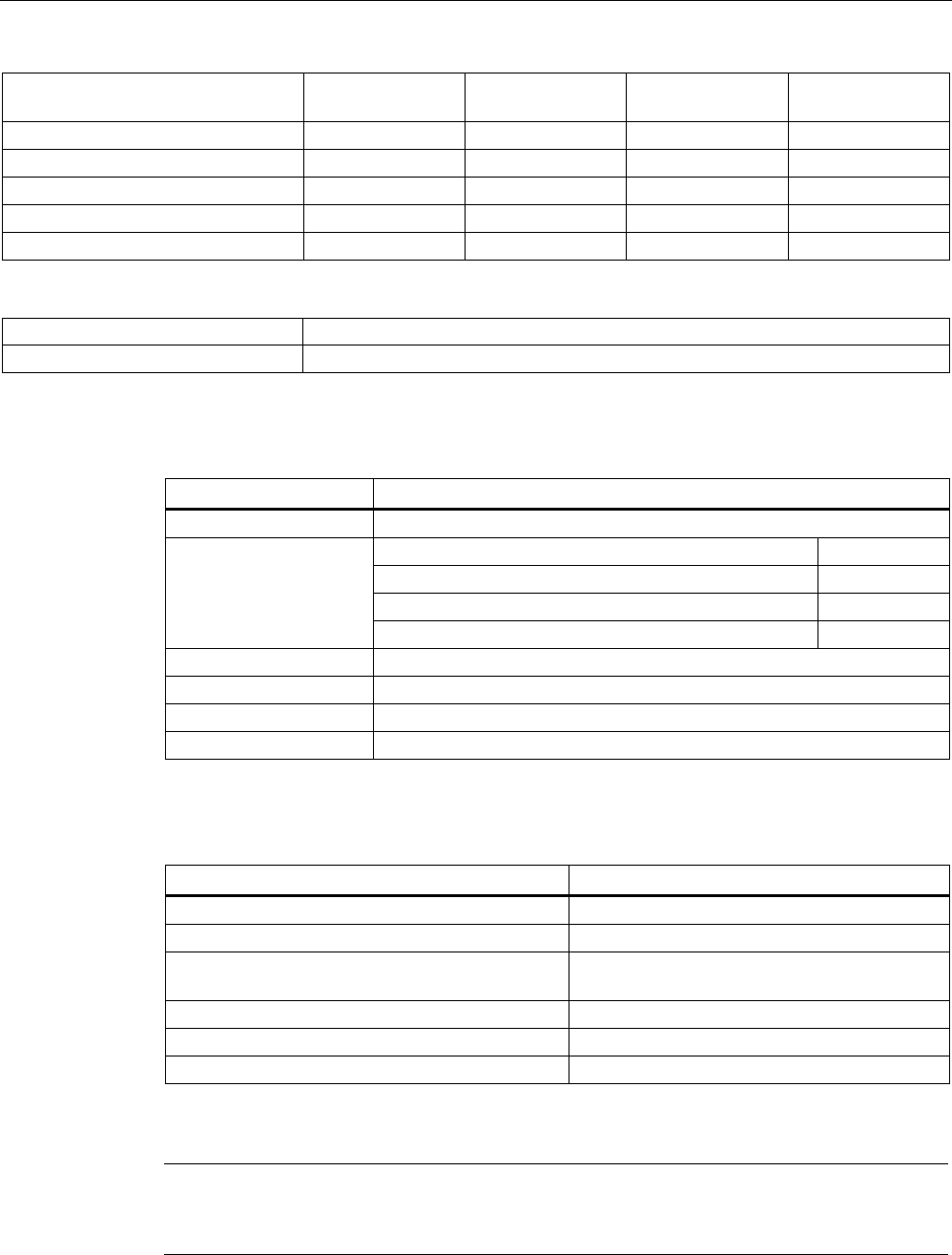
Transponder/tags
7.4 SIMATIC RF610T
SIMATIC RF600
294 System Manual, 05/2012, J31069-D0171-U001-A13-7618
Write distance
typical
RF640R/RF670R/
with RF660A
RF640R RF620R/RF630R
with RF660A
RF620R
Paper/cardboard 0.2 m ... 3.0 m 0.2 m to 2.7 m 0.2 m ... 1.8 m 0.2 m ... 0.7 m
Plastic film 0.2 m ... 3.0 m 0.2 m to 2.7 m 0.2 m ... 1.8 m 0.2 m ... 0.7 m
Plastic 0.2 m ... 1.0 m 0.2 m to 0.9 m 0.2 m ... 0.7 m 0.2 m ... 0.5 m
Wood 0.2 m ... 1.0 m 0.2 m to 0.9 m 0.2 m ... 0.7 m 0.2 m ... 0.5 m
Glass 0.2 m ... 1.0 m 0.2 m to 0.9 m 0.2 m ... 0.7 m 0.2 m ... 0.5 m
Energy source Field energy via antenna, without battery
Multi-tag capability Yes
7.4.6.3 Memory specifications
Property Description
Type EPC Class 1 Gen 2
EPC code 96 bits/240 bits
User memory 512 bits
TID 64 bits
Memory organization
Reserved (passwords) 64 bits
Protocol ISO 18000-6C
Data retention time 10 years
Read cycles Unlimited
Write cycles Minimum at +22 °C 100 000
7.4.6.4 Environmental conditions
Feature Description
Temperature range during operation -25 °C … +85 °C
Temperature range during storage -40 °C … +85 °C
Shock resistant acc. to EN 60068-2-27
Vibration acc. to EN 60068-2-6
100 g1
50 g1
Torsion and bending load Partially permissible
Distance from metal Not suitable for fixing straight onto metal
Degree of protection IP67
1) The values for shock and vibration are maximum values and must not be applied
continuously.
Note
Note that in temperature ranges > 70 °C, the transponder can become slightly deformed.
However, this has no effect on the transponder function.
Transponder/tags
7.4 SIMATIC RF610T
SIMATIC RF600
System Manual, 05/2012, J31069-D0171-U001-A13-7618 295
7.4.7 Certificates and approvals
Certificate Description
Conformity with R&TTE directive
FCC
Federal Communications
Commission
Passive labels and transponders comply with the valid regulations;
certification is not required.
This product is UL-certified for the USA and Canada.
It meets the following safety standard(s):
• UL508 - Industrial Control Equipment
• CSA C22.2 No. 142 - Process Control Equipment
• UL Report E 120869
7.4.8 Dimension drawing
6,0$7,&5)7*7%%$6$
s
º
º
Figure 7-15 Dimensional drawing of SIMATIC RF610T
All dimensions in mm
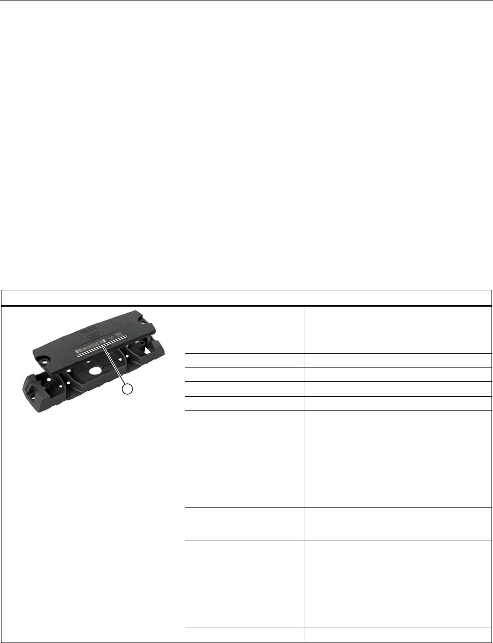
Transponder/tags
7.5 SIMATIC RF620T
SIMATIC RF600
296 System Manual, 05/2012, J31069-D0171-U001-A13-7618
7.5 SIMATIC RF620T
7.5.1 Characteristics
The SIMATIC RF620T Transponder is passive and maintenance-free, based on the UHF
Class 1 Gen2 technology for storing 96-bit/128-bit electronic product codes (EPC).
The transponder also has a 64-byte user memory.
The container tag for industrial applications is rugged and highly resistant to detergents. It is
designed for easy attachment onto plastic, wood, glass, e.g. containers, palettes, and
trolleys
The optimum functionality/range of the RF620T on metal is achieved by means of the
spacer.
Since the plastic is food safe, it is also suitable for use in the food-processing industry.
This container tag is designed for the frequency bands of 860 MHz and 960 MHz and can be
operated in combination with our UHF system RF660.
SIMATIC RF620T Transponder Features
Application Transponder for rugged, industrial
requirements such as RF identification in
warehouses and the logistics and transport
area.
Frequency band 860 to 960 MHz
Polarization Linear
Memory EPC 96 bit/128 bit
Additional USER memory 64 byte
Read/write range
• with non-metallic
carriers
• direct on metallic
carriers
• with spacer on metallic
carriers
• Typically 0.2 to 8°m
• Typically 0.2 to 3°m
• Typically 0.2 to 7 m
Mounting • Screw, bond
• On metal by means of spacers
① Labeling area You can inscribe the transponder itself using
laser, or adhere a label to position ①.
Possible types of labeling:
• Barcode
• Inscription in plain text
• Data matrix code
Housing color Anthracite
Transponder/tags
7.5 SIMATIC RF620T
SIMATIC RF600
System Manual, 05/2012, J31069-D0171-U001-A13-7618 297
7.5.2 Ordering data
Ordering data Order number
SIMATIC RF620T
• Frequency 865 MHz to 928 MHz,
• UHF Class 1 Gen2 technology (96 bit/128 bit)
• -25 °C to +85 °C operating temperature
• Dimensions (L x W x H) 127 x 38 x 6 mm
• IP67 degree of protection
6GT2810-2HC81
Spacer for SIMATIC RF620T
• For attaching to metal surfaces
• Dimensions (L x W x H) 155 x 38 x 12 mm
6GT2898-2AA00
7.5.3 Planning the use
7.5.3.1 Reading range when mounted on non-metallic carriers
The transponder is generally designed for mounting on non-metallic objects which provide
the conditions for the maximum reading ranges
Table 7- 10 Reading range on non-metallic carriers
Carrier plate material Reading range
Transponder on wooden carrier
(dry, degree of moisture < 15%)
typ. 6 m
Transponder on plastic carrier typ. 6 m
Transponder on glass typ. 6 m
Transponder on plastic mineral water bottle typ. 1.2 m
100% reading range is achieved when mounted in empty, anechoic rooms.
7.5.3.2 Directional radio pattern of the transponder on non-metallic surfaces
Preferably, align the data carrier parallel to the transmitting antenna. If, however, the data
carrier including the metallic carrier plate is tilted, the reading range will be reduced.
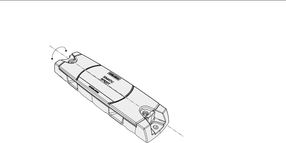
Transponder/tags
7.5 SIMATIC RF620T
SIMATIC RF600
298 System Manual, 05/2012, J31069-D0171-U001-A13-7618
Rotation about the polarization axis
3RODUL]DWLRQD[LV
Figure 7-16 Rotation of the transponder about the polarization axis
Generally the range does not change when the transponder without carrier material is
rotated about the polarization axis.
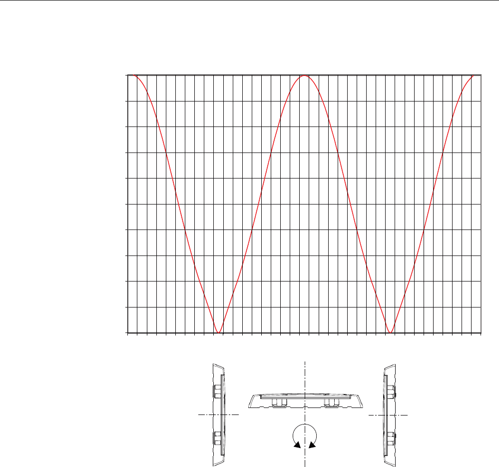
Transponder/tags
7.5 SIMATIC RF620T
SIMATIC RF600
System Manual, 05/2012, J31069-D0171-U001-A13-7618 299
Rotation orthogonal to the polarization axis
0
10
20
30
40
50
60
70
80
90
100
-180 -160 -140 -120 -100 -80 -60 -40 -20 0 20 40 60 80 100 120 140 160 180
$QJOHGHJUHHV
5DQJH
Figure 7-17 Transponder characteristics when rotated orthogonally to the polarization axis (within the
tag plane)
If the transponder is positioned orthogonally to the transmitting antenna, it normally cannot
be read. Therefore the data carrier is preferably to be aligned parallel to the transmitting
antenna. The following figure illustrates this situation.
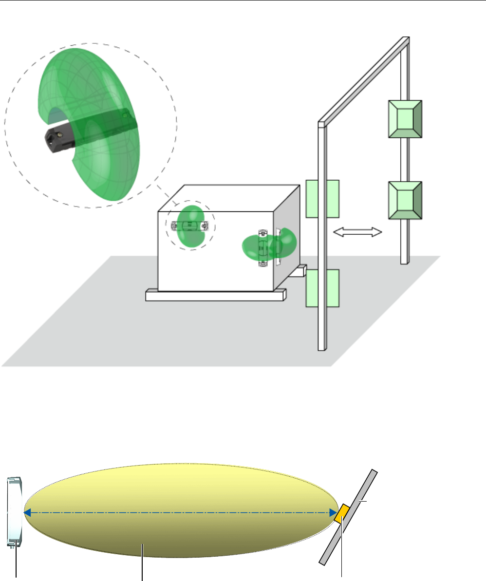
Transponder/tags
7.5 SIMATIC RF620T
SIMATIC RF600
300 System Manual, 05/2012, J31069-D0171-U001-A13-7618
Figure 7-18 Application example for possible orientations of the transponder.
7.5.3.3 Optimum antenna/transponder positioning with planar mounting of the transponder on
metal
7UDQVSRQGHU
5)7
0HWDOFDUULHU
5)5
5)5
$QWHQQDILHOG
:ULWLQJUHDGLQJUDQJHVHHWHFKQLFDOGDWD
6HQGDQGUHFHLYH
Figure 7-19 Example of optimum reader-transponder positioning with RF620R and RF640R via the internal reader
antenna.
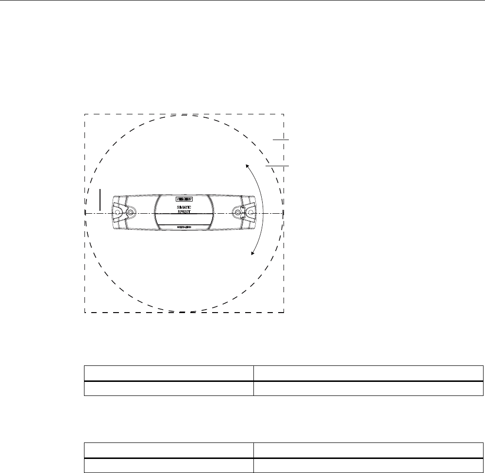
Transponder/tags
7.5 SIMATIC RF620T
SIMATIC RF600
System Manual, 05/2012, J31069-D0171-U001-A13-7618 301
7.5.3.4 Reading range when mounted on flat metallic carrier plates
The transponder generally has linear polarization. The polarization axis runs as shown in the
diagram below. If the tag is centrically mounted on a flat metal plate, which may either be
almost square or circular, it can be aligned in any direction since the transmitting and
receiving RF660A antennas operate with circular polarization.
3RODUL]DWLRQD[LV
6TXDUH
PHWDOVXSSRUW
&LUFXODUPHWDO
FDUULHUSODWH
r
Figure 7-20 Optimum positioning of the transponder on a (square or circular) metal carrier plate
Table 7- 11 Reading range with metallic, plane carriers without spacer
Carrier plate material Reading range
Metal plate at least 300 x 300 mm Typ. 3 m
Table 7- 12 Reading range with metallic, plane carriers with spacer
Carrier plate material Reading range
Metal plate at least 300 x 300 mm Typ. 7 m
The use of spacers on metallic surfaces is therefore recommended.
On rectangular carrier plates, the reading distance depends on the mounting orientation of
the transponder A 90° rotation of the transponder about the axis of symmetry may result in
greater reading distances
7.5.3.5 Influence of conducting walls on the reading range
If there are conducting walls or restrictions in the vicinity that could shade the radio field, a
distance of approx. 10 cm is recommended between the transponder and the wall In
principle, walls have least influence if the polarization axis is orthogonal to the conducting
wall. A spacer must be used in any case.
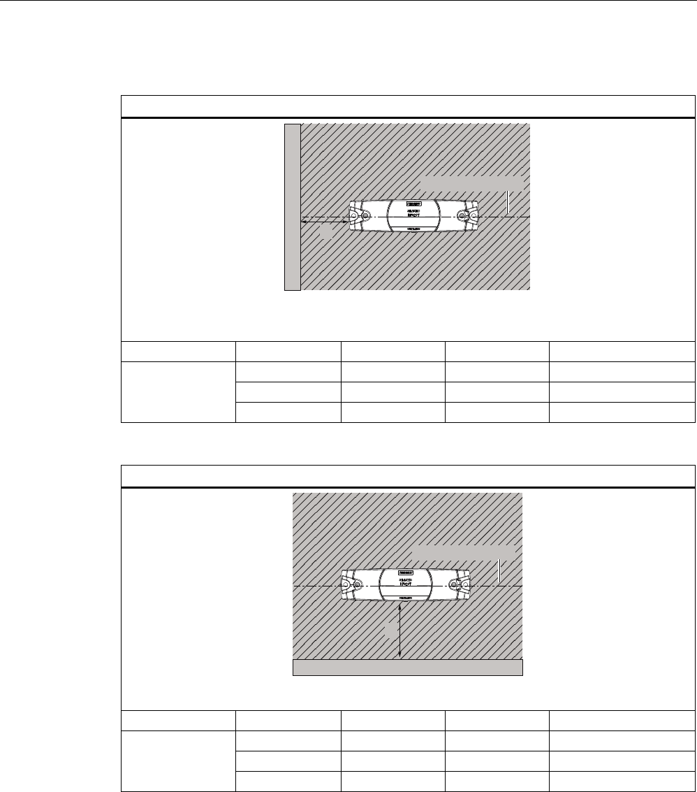
Transponder/tags
7.5 SIMATIC RF620T
SIMATIC RF600
302 System Manual, 05/2012, J31069-D0171-U001-A13-7618
Reading range: One conducting wall
Dependence of the reading distance when positioned orthogonally to the conducting wall
G
&RQGXFWLQJZDOO
3RODUL]DWLRQD[LV
Top view
Distance d 20 mm 50 mm 100 mm
Approx. 100% Approx. 100% Approx. 100% Wall height 20 mm
Approx. 100% Approx. 100% Approx. 100% Wall height 50 mm
Reading range
Approx. 80% Approx. 100% Approx. 100% Wall height 100 mm
Dependence of the reading distance when positioned parallel to the conducting wall
G
&RQGXFWLQJZDOO
3RODUL]DWLRQD[LV
Top view
Distance d 20 mm 50 mm 100 mm
Approx. 70 % Approx. 100% Approx. 100% Wall height 20 mm
Approx. 60 % Approx. 90 % Approx. 100% Wall height 50 mm
Reading range
Approx. 30 % Approx. 70 % Approx. 100% Wall height 100 mm

Transponder/tags
7.5 SIMATIC RF620T
SIMATIC RF600
System Manual, 05/2012, J31069-D0171-U001-A13-7618 303
Reading range: Two conducting walls
Influence on reading range when positioned against two conducting walls
G
G
&RQGXFWLQJZDOO
&RQGXFWLQJZDOO
3RODUL]DWLRQD[LV
Top view
G
&RQGXFWLQJZDOO
&RQGXFWLQJZDOO
:DOOKHLJKW
Side view
Distance d 20 mm 50 mm 100 mm
Approx. 70 % Approx. 100% Approx. 100% Wall height 20 mm
Approx. 60 % Approx. 90 % Approx. 100% Wall height 50 mm
Reading range
Approx. 30 % Approx. 70 % Approx. 100% Wall height 100 mm
The values specified in the tables above are reference values.
7.5.3.6 Directional radio pattern of the transponder on metallic surfaces
Preferably, align the data carrier parallel to the transmitting antenna. If, however, the data
carrier including the metallic carrier plate is tilted, the reading range will be reduced.
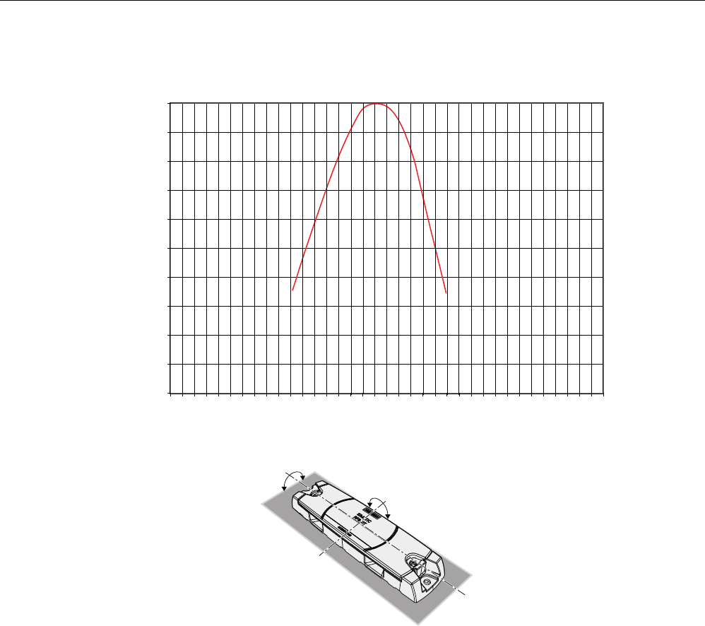
Transponder/tags
7.5 SIMATIC RF620T
SIMATIC RF600
304 System Manual, 05/2012, J31069-D0171-U001-A13-7618
Rotation about the polarization axis or orthogonal to the polarization axis
r
r
r
r
0
10
20
30
40
50
60
70
80
90
100
-170
-150
-130
-110
-90
-70
-50
-30
-10
10
30
50
70
90
110
130
150
170
3RODUL]DWLRQD[LV
2UWKRJRQDOD[LV
5HDGLQJUDQJH
$QJOHGHJUHHV
Figure 7-21 Characteristic of the transponder when rotated about the polarization axis or orthogonally
to the polarization axis
7.5.3.7 Reading range when mounted on ESD carrier materials
The transponder is generally designed for mounting on non-conductive objects which
provide the conditions for the maximum reading ranges The conductive or dissipativesurface
of ESD materials limits the reading range depending on the surface resistance. Generally,
dissipative materials with a surface resistance of 1 x 10⁵ to 1 x 10¹¹ ohm and conductive
materials with 1 x 10³ to 1 x 10⁵ ohm are available.
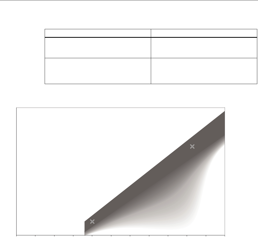
Transponder/tags
7.5 SIMATIC RF620T
SIMATIC RF600
System Manual, 05/2012, J31069-D0171-U001-A13-7618 305
Table 7- 13 Limited reading range with ESD materials
Carrier plate material Reading range
Transponder on electrostatic dissipative
materials, dimensions 60°x°40 cm
(surface resistance 2 x 10⁹ ohm)
Approx. 4 m
Transponder on electrostatic conductive
materials, dimensions 60 x 40 cm
(surface resistance 1 x 10⁴ ohm)
Use of spacers
Approx. 1 m
Approx. 2 m
100% reading range is achieved when mounted in empty, anechoic rooms. With multi-tag
capability, limitations may result in the reading range.
0
10
20
30
40
50
60
70
80
90
100
1x10
0
1x10
1
1x10
2
1x10
3
1x10
4
1x10
5
1x10
6
1x10
7
1x10
8
1x10
9
1x10
10
1x10
11
5HDGLQJUDQJH
6XUIDFHUHVLVWDQFHRKP
Figure 7-22 Schematic representation of how the reading range depends on the surface resistance of the ESD material
In the representation above, the two reading points with regard to the dependence of the
reading range in % on the surface resistance are shown At the same time a linear
dependence between the reading points is to be expected, however with measurement
inaccuracies. The darker the hatching, the greater the probability that the reading point is
found in the hatched area.
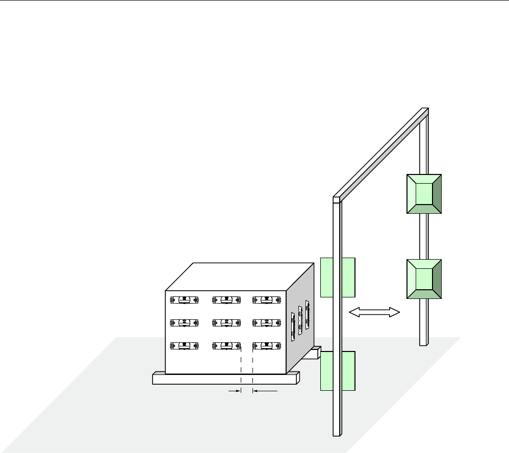
Transponder/tags
7.5 SIMATIC RF620T
SIMATIC RF600
306 System Manual, 05/2012, J31069-D0171-U001-A13-7618
7.5.3.8 Communication with multiple transponders
The RF600 system is multitag-capable. This means that the reader can detect and write to
several transponders almost simultaneously. The minimum distance between the
transponders is ≥ 50 mm.
PP
Figure 7-23 Multitag reading
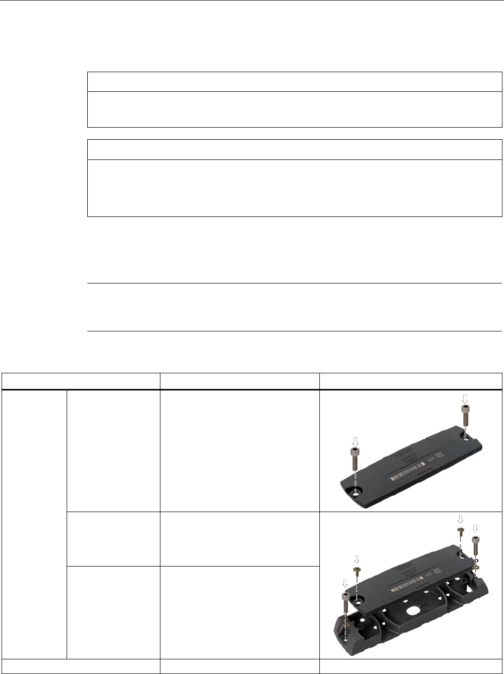
Transponder/tags
7.5 SIMATIC RF620T
SIMATIC RF600
System Manual, 05/2012, J31069-D0171-U001-A13-7618 307
7.5.4 Mounting instructions
CAUTION
Level mounting
Please note that both the transponder and the spacer must be mounted on a level surface.
CAUTION
The screw fixing element was tested with the types of screws, spring washers and plain
washers indicated below. Depending on the application area, the user must use similar,
correspondingly certified screws, spring washers and plain washers (e.g. for the food
processing industry).
EJOT screws can be additionally etched and passivated in some areas of the food
processing industry, e.g if they made of stainless steel A2. In other areas without special
requirements, the screws can be, for example, zinc plated and blue passivated.
Note
In case of high mechanical loads (such as shocks or vibration), the transponder must be
fixed onto the spacer by means of screws.
Properties Description Graphics
• Transponder • Screw mounting (e.g. 2 x M4
hexagon socket head cap screws
DIN 6912, spring lock and
grommet DIN 433)
or glued
• Transponder on
spacer
• Clips or screw on the side of the
clip, or 2°x° screws (e.g.
EJOT PT ® WN 5411 35x10 VZ
crosshead screw/torx)
Mounting type
• Spacer • Screw mounting (e.g.°2 x M4
hexagon socket head cap screws
DIN 6912, spring lock and
grommet DIN 433) or glued or
secured with tape
Tightening torque (at room temperature) < 1.2 Nm

Transponder/tags
7.5 SIMATIC RF620T
SIMATIC RF600
308 System Manual, 05/2012, J31069-D0171-U001-A13-7618
7.5.5 Memory configuration of the transponder
The memory configuration of the transponder is described in the section SIMATIC memory
configuration of the RF600 transponders and labels (Page 270).
7.5.6 Technical Specifications
7.5.6.1 Mechanical data
Property Description
Dimensions (L x W x H)
• Transponder
• Spacer
• 127 x 38 x 6 mm
• 157 x 39 x 12 mm
Design Plastic enclosure (PP; food safe), silicon-free
Housing color Anthracite
Weight
• Transponder
• Spacer
• Transponder with spacer
• Approx. 18 g
• Approx. 22 g
• Approx. 40 g
Mounting on metal Preferably with spacer
7.5.6.2 Electrical data
Characteristic Description
Air interface According to ISO 18 000/ISO -6
Frequency band 860 to 960 MHz
Read distance
• on non-metallic carriers
• on metallic carriers
• on conductive plastic
• on metal using spacers1)
• Typ. 8 m
• Typ. 3 m
• Typ. 1 m
• Typ. 7 m
Write distance
• non-metallic carriers
• on metallic carriers
• on conductive plastic
• on metal using spacers1)
• Typ. 5.6 m
• Typ. 2.1 m
• Typ. 0.7 m
• Typ. 4.9 m
Polarization type Linear
Minimum distance to transmitting
antenna
Approx. 0.2 m