Siemens RF600R RFID UHF Reader User Manual SIMATIC RF600
Siemens AG RFID UHF Reader SIMATIC RF600
UserManual.wiki
>
Siemens
>
RF600R User Manual
>
User manual 01
Contents
1.
User manual 01
2.
User manual 02
3.
User manual 03
4.
User manual 04
5.
User manual 05
User manual 01
Navigation menu
Upload a User Manual
Namespaces
Wiki Guide
HTML
PDF
Info
Views
User Manual
Discussion / Help
Navigation
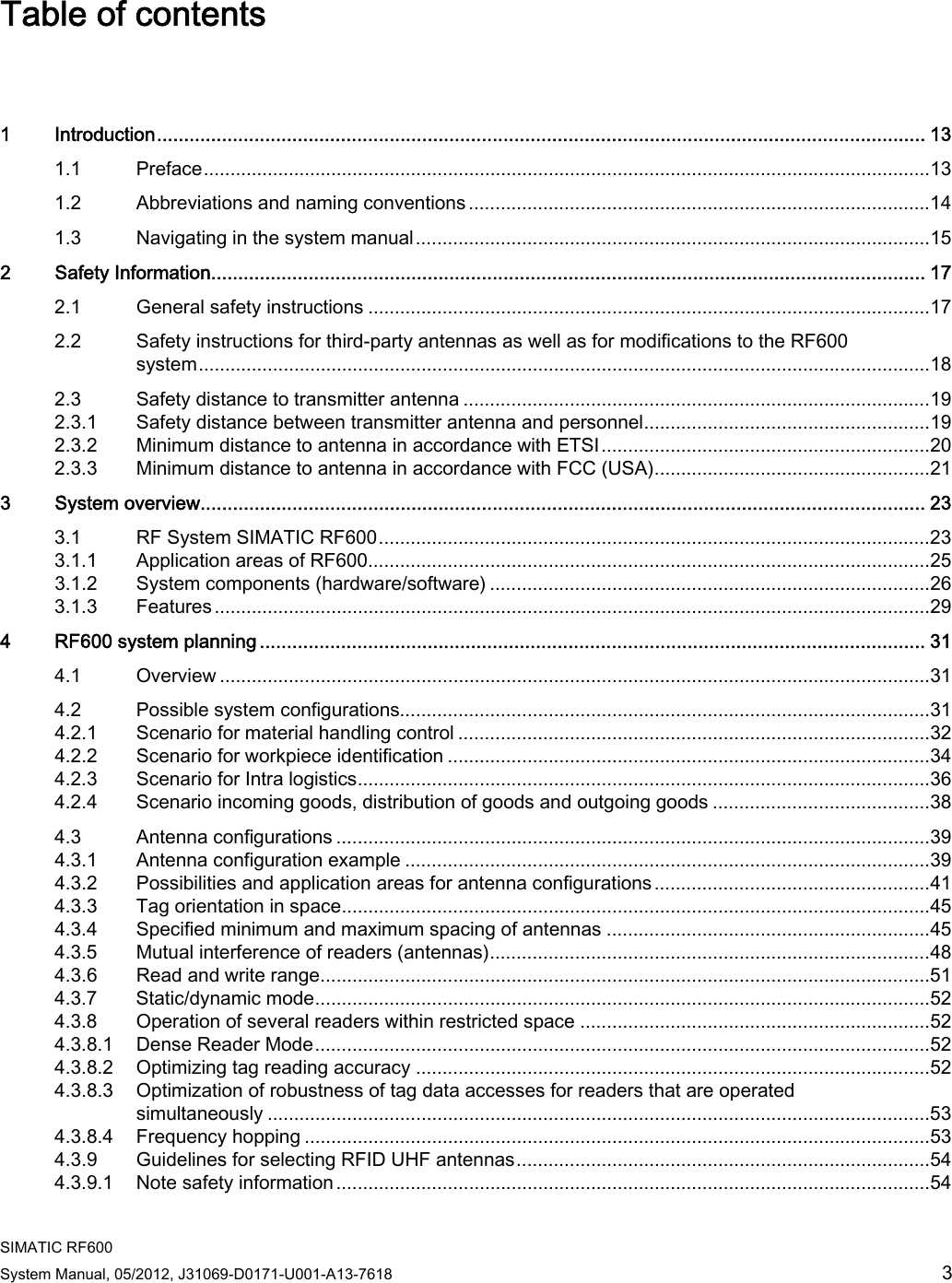
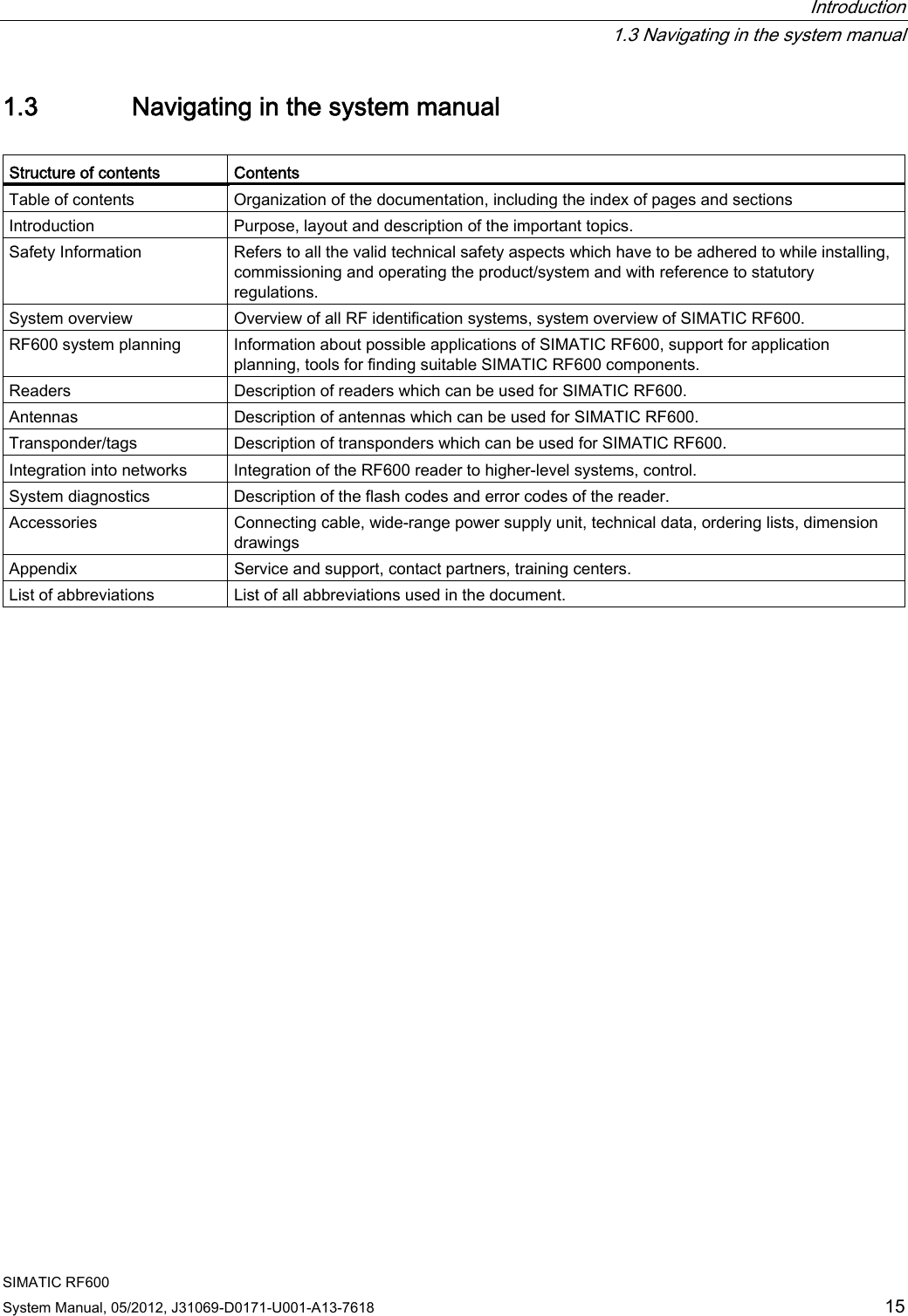
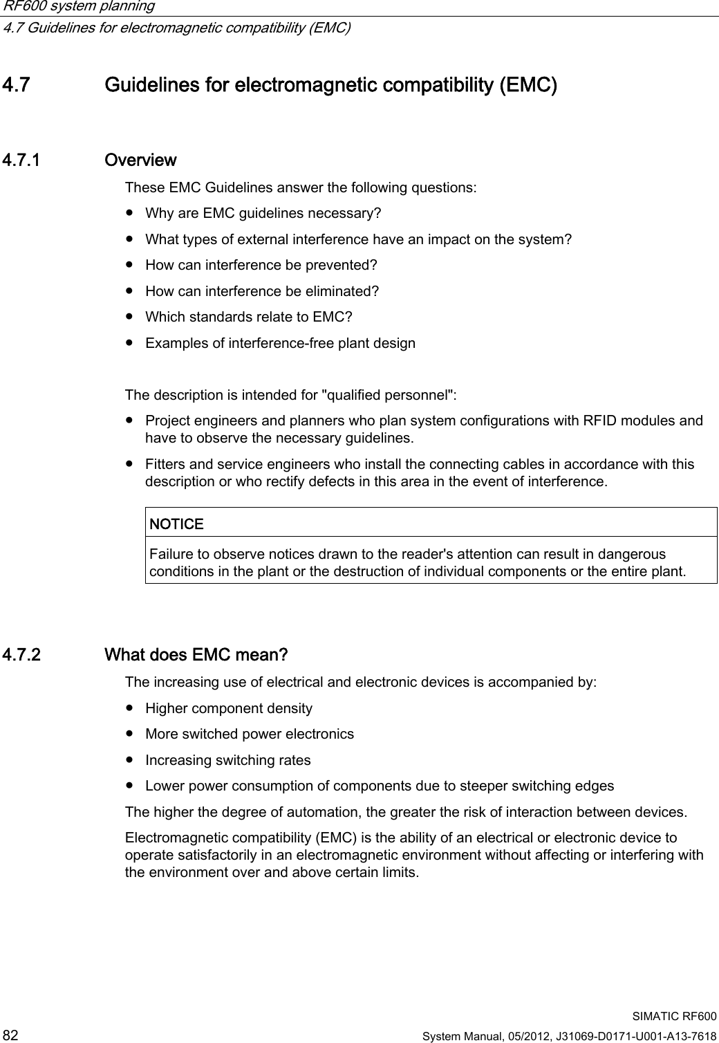
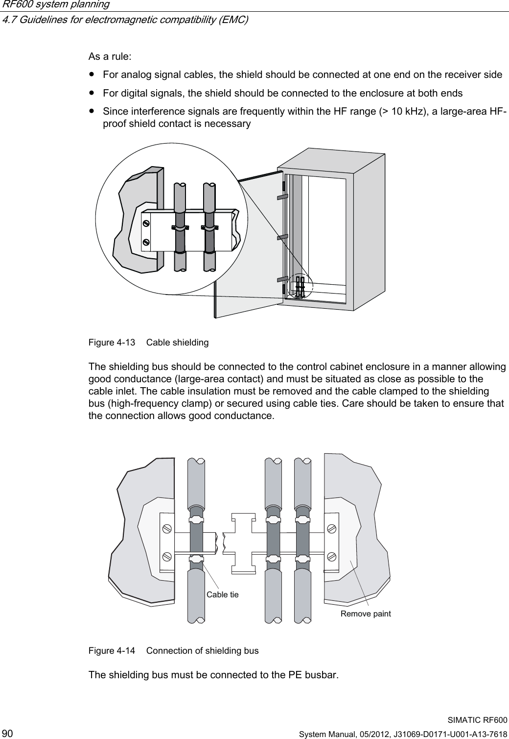
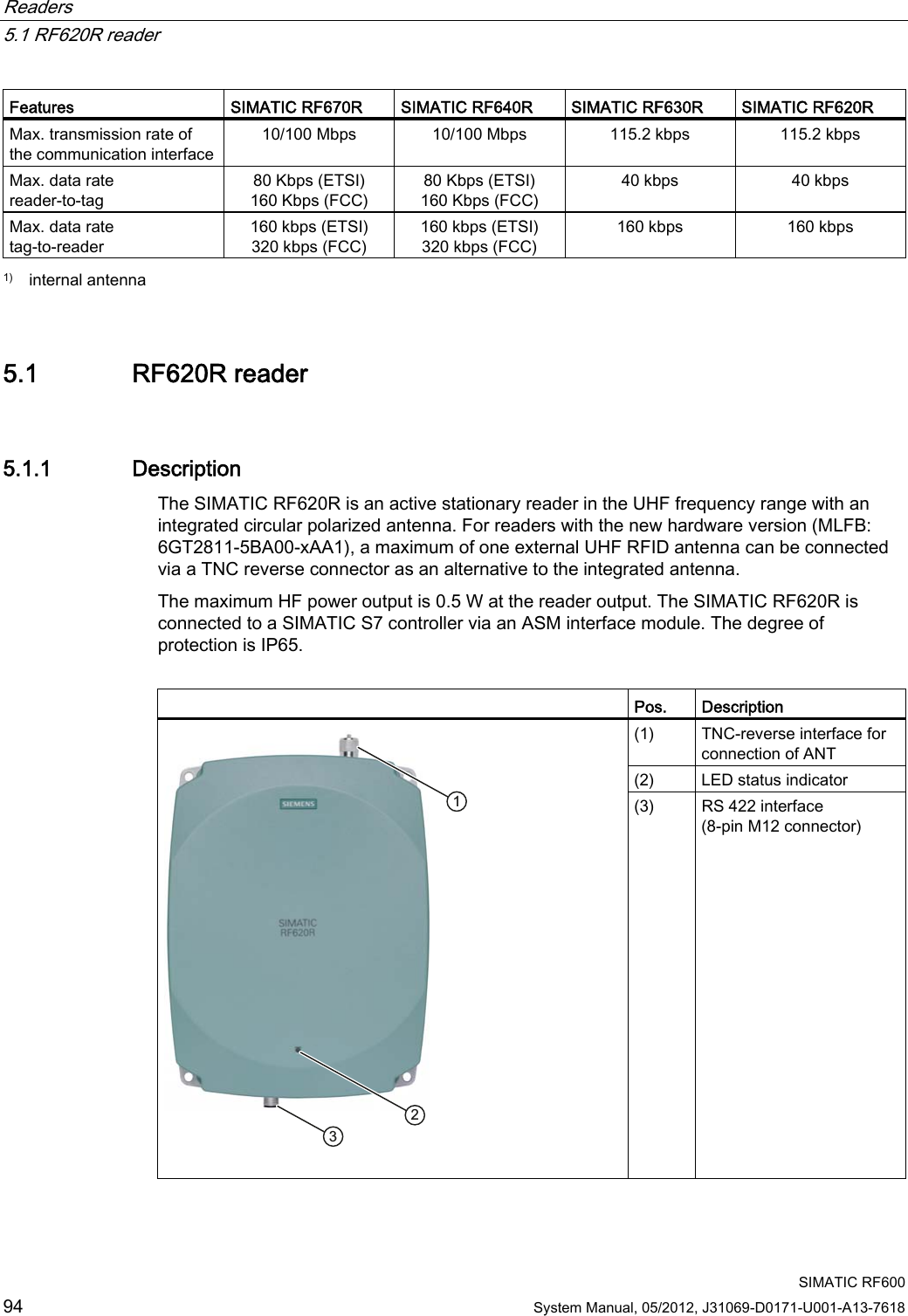
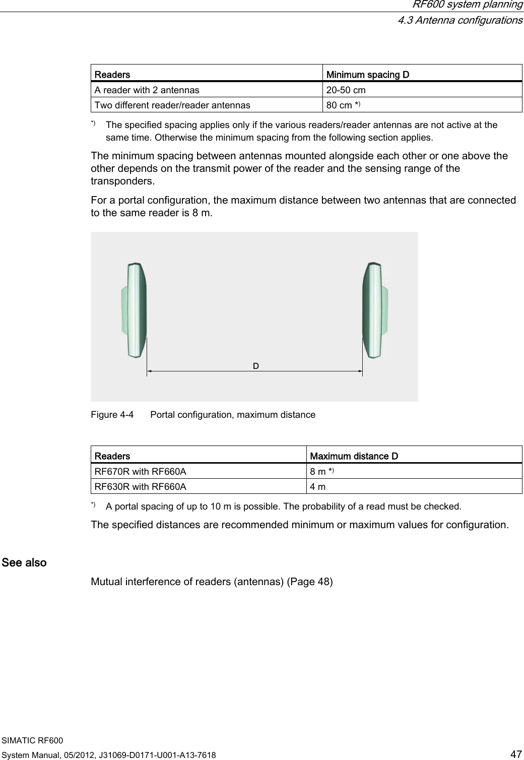
![Safety Information 2.3 Safety distance to transmitter antenna SIMATIC RF600 System Manual, 05/2012, J31069-D0171-U001-A13-7618 19 Note User responsibility for modified product As a user of the modified product, you accept responsibility for use of the complete RFID product comprising both SIMATIC RF600 components and third-party RFID components. This particularly applies to modification or replacement of: • Antennas • Antenna cables • readers • Power supply units with connection cables 2.3 Safety distance to transmitter antenna 2.3.1 Safety distance between transmitter antenna and personnel For antenna configurations where it is possible to be briefly or constantly within the transmission range of the antennas, as in loading ramps, for example, minimum distances must be maintained. Limits The ICRP (International Commission of Radiological Protection) has worked out limit values for human exposure to HF fields that are also recommended by the ICNIRP (International Commission of Non Ionizing Radiological Protection). In German legislation on emissions (since 1997), the following limit values apply. These can vary according to frequency: Frequency f [MHz] Electrical field strength E [V/m] Magnetic field strength H [A/m] 10 - 400 27,5 0,073 400 - 2.000 1.375 x f1/2 0.0037 x f1/2 2.000 - 300.000 61 0,16 The limit values for the 900 MHz reader antenna alternating field are thus: Electrical field strength: E = 41.25 V/m Magnetic field strength: H = 0.111 A/m HF power density: E x H = 4.57 W/m2](https://usermanual.wiki/Siemens/RF600R.User-manual-01/User-Guide-1716290-Page-21.png)
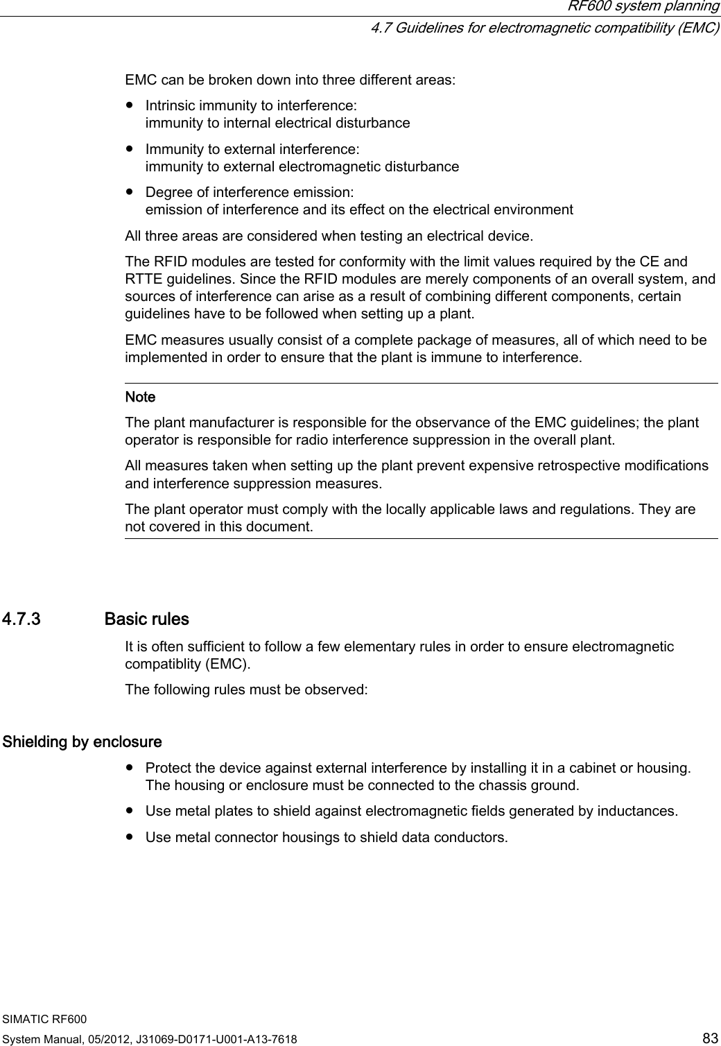
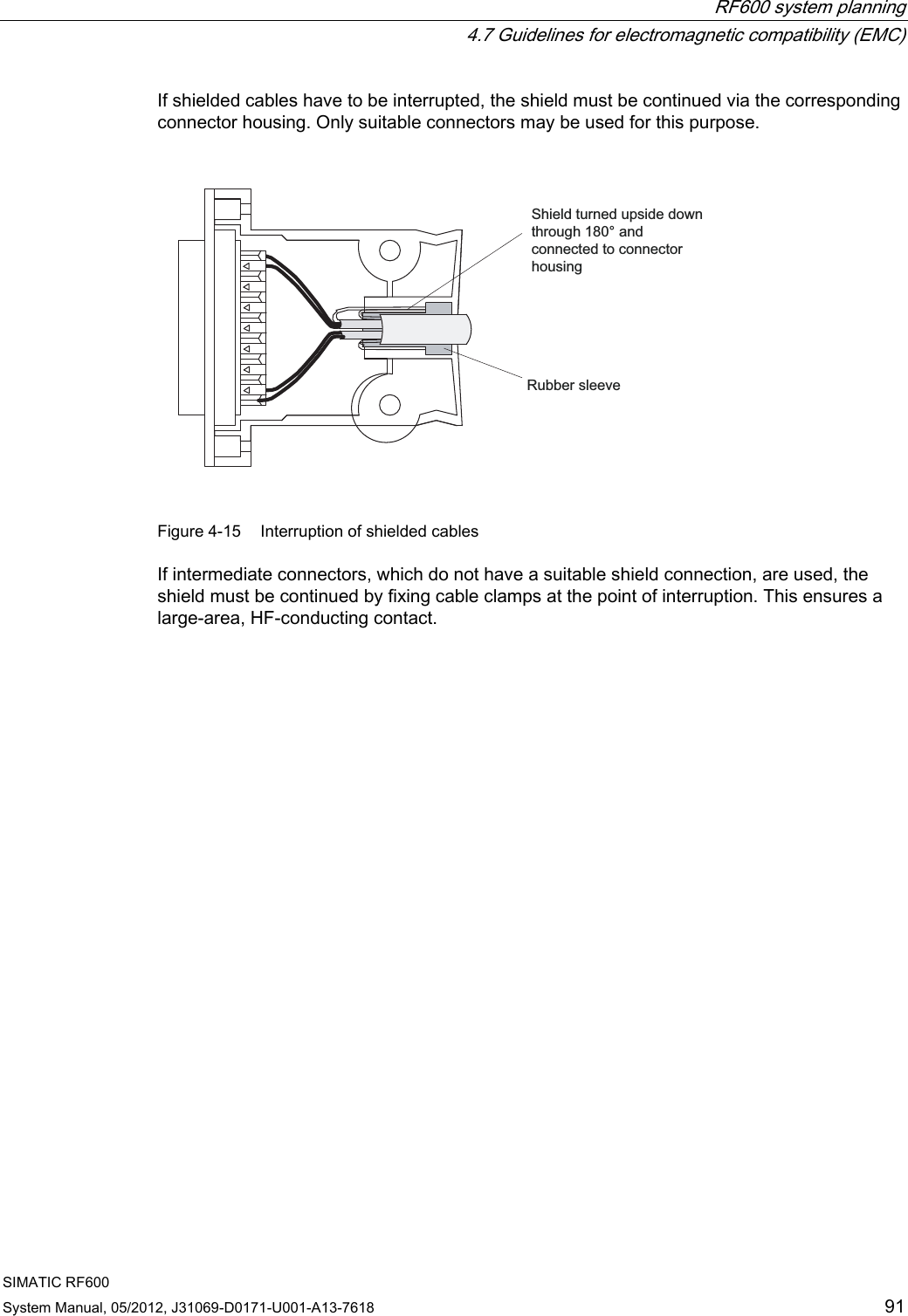
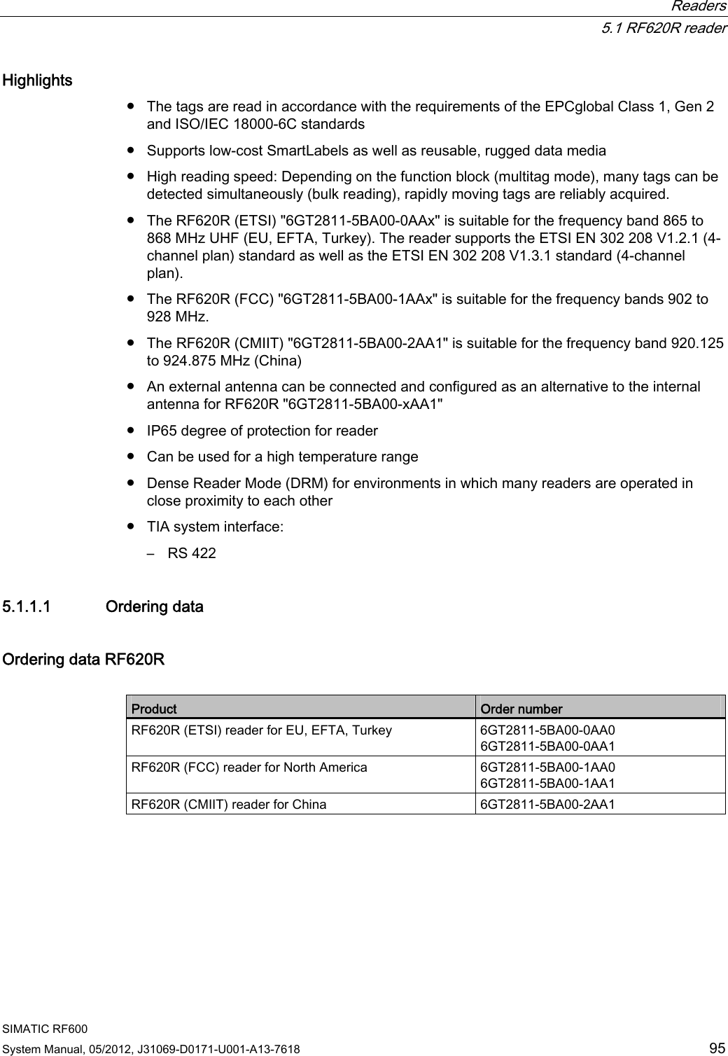
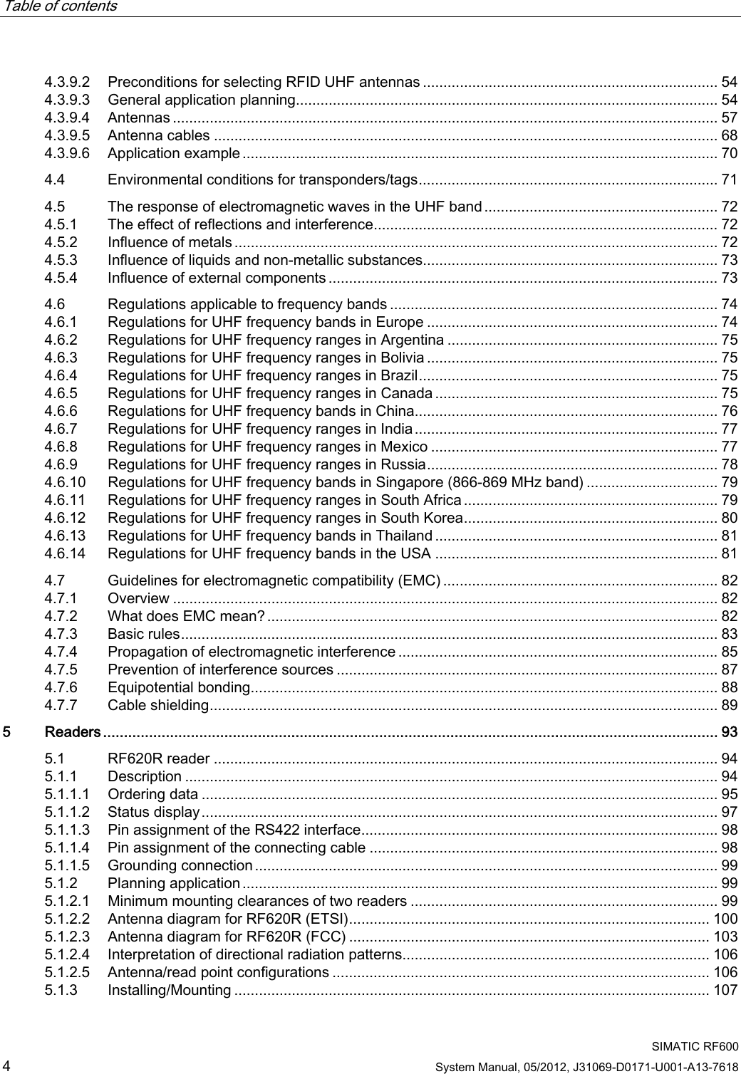
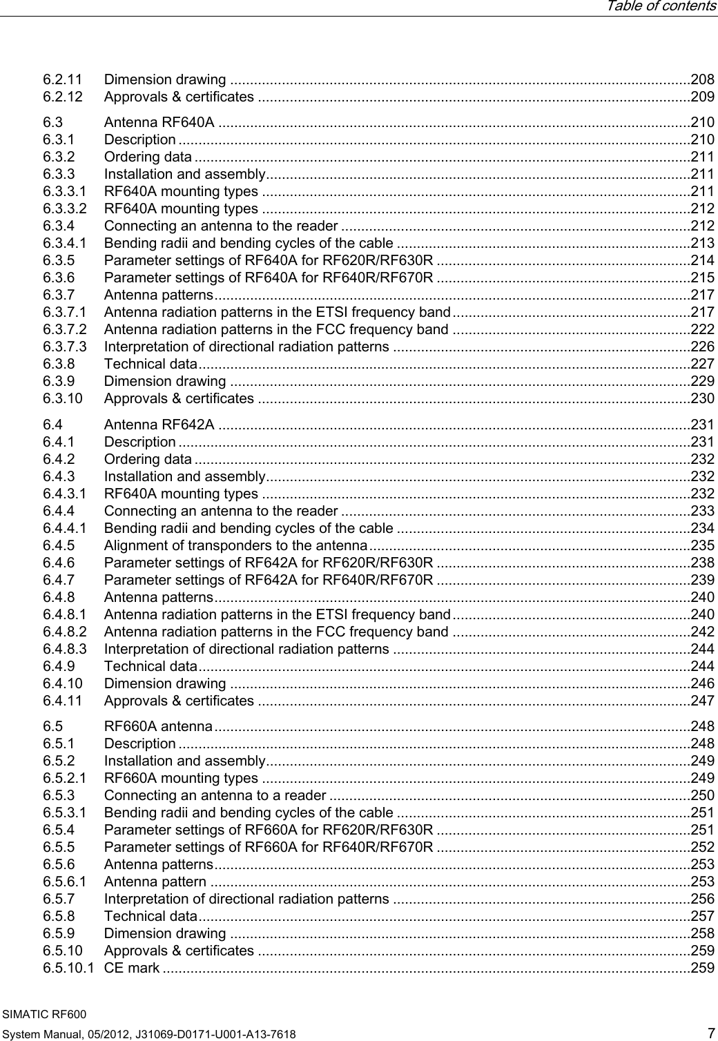
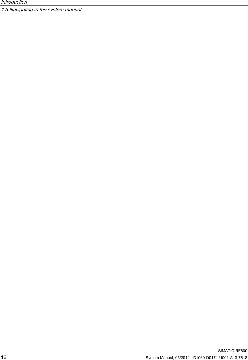
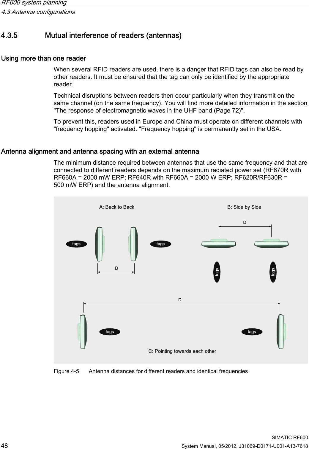
![Safety Information 2.3 Safety distance to transmitter antenna SIMATIC RF600 20 System Manual, 05/2012, J31069-D0171-U001-A13-7618 2.3.2 Minimum distance to antenna in accordance with ETSI Minimum distance to antenna in accordance with ETSI (EU, EFTA, Turkey) At a transmission frequency of 900 MHz, the wavelength of the electromagnetic wave λ is approximately 0.34 m. For distances less than 1 λ in the near field, the electrical field strength (1/r) diminishes exponentially to the power three over distance, and for distances greater than 1 λ, it diminishes exponentially to the power two over distance. 01020304050607080901000,1 0,2 0,3 0,4 0,5 0,6 0,7 0.8 0.9 1(OHFWULFDOILHOGVWUHQJWKDWDGLVWDQFHIURPWKH7;DQWHQQDIRU3 :(53'LVWDQFHP)LHOGVWUHQJWK9P The horizontal line at 41.25V/m marks the "safety limit value". For the maximum permissible transmit power (1/r2) in accordance with ETSI (2W ERP), the "safety distance" d = 0.24 m. This means that personnel should not remain closer than 24cm to the transmitter antenna for extended periods (more than several hours without interruption). Remaining within the vicinity of the antenna for a brief period, even for repeated periods (at a distance < 0.24 m), is harmless according to current knowledge. Distance to transmitter antenna [m] Feld strength [V/m] % of limit value 1 10 24 5 2 5 If the transmitter power is set lower than the highest permissible value (2 watts ERP), the "safety distance" reduces correspondingly. The values for this are as follows: Radiated power ERP [W] Safety distance to transmitter antenna [m] 2.0 0.24 1.0 0.17 0.5 0.12](https://usermanual.wiki/Siemens/RF600R.User-manual-01/User-Guide-1716290-Page-22.png)
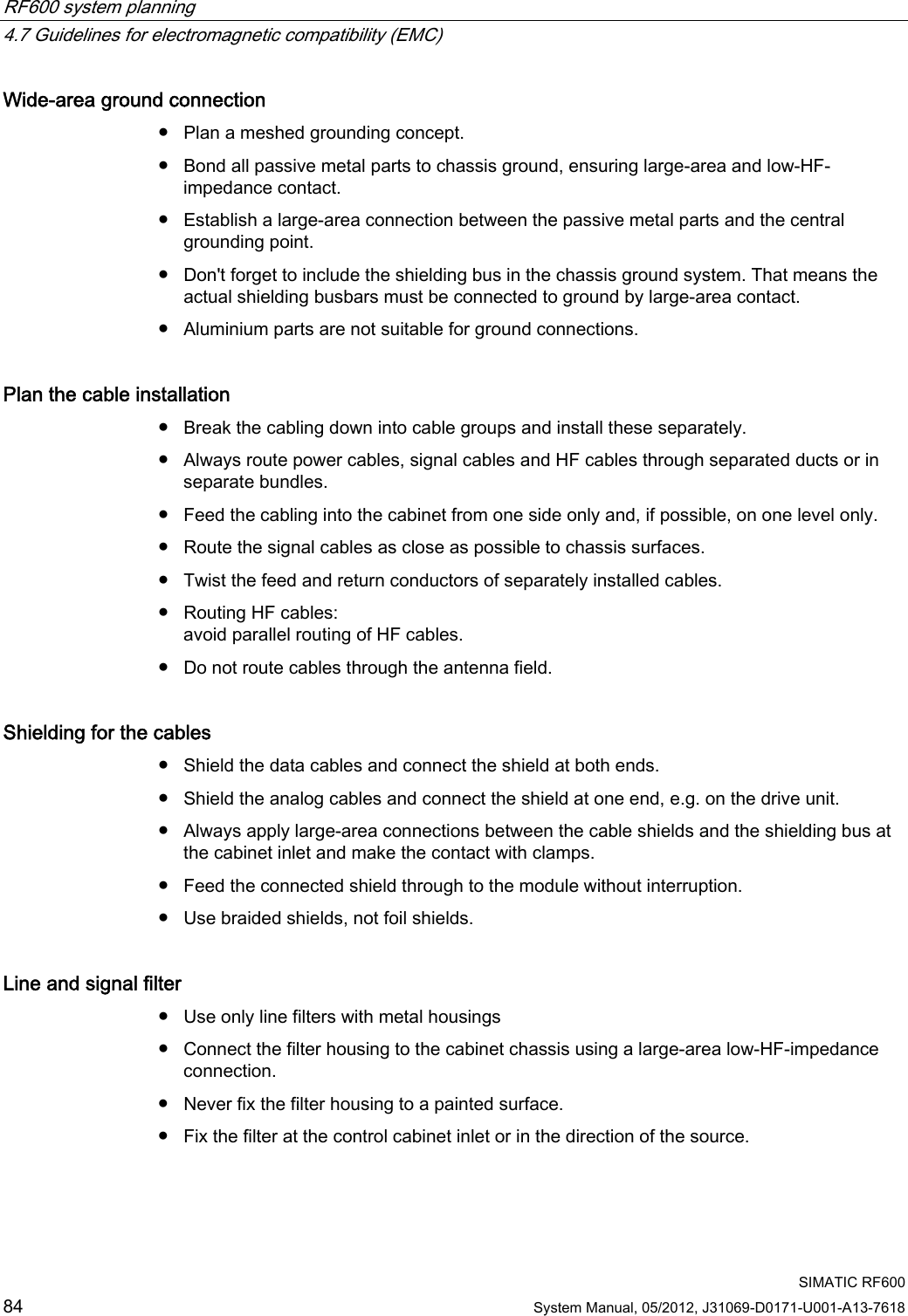
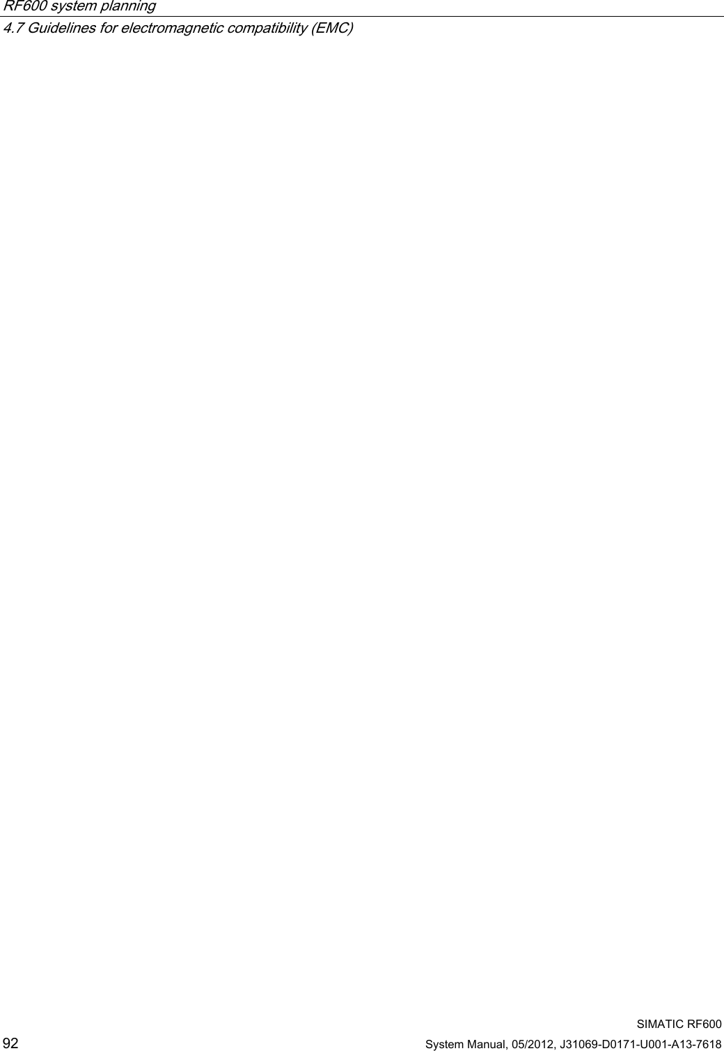
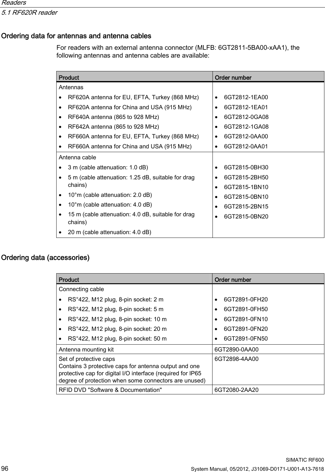
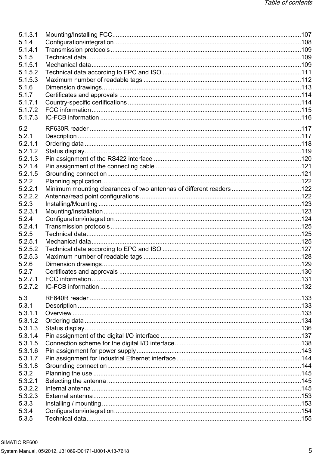
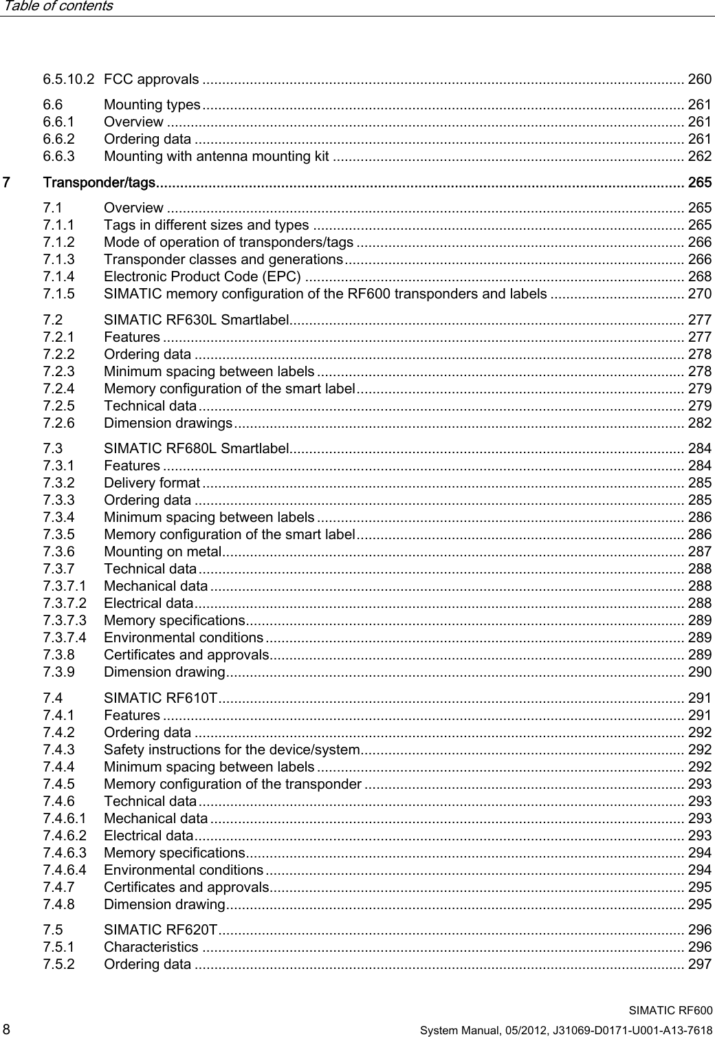
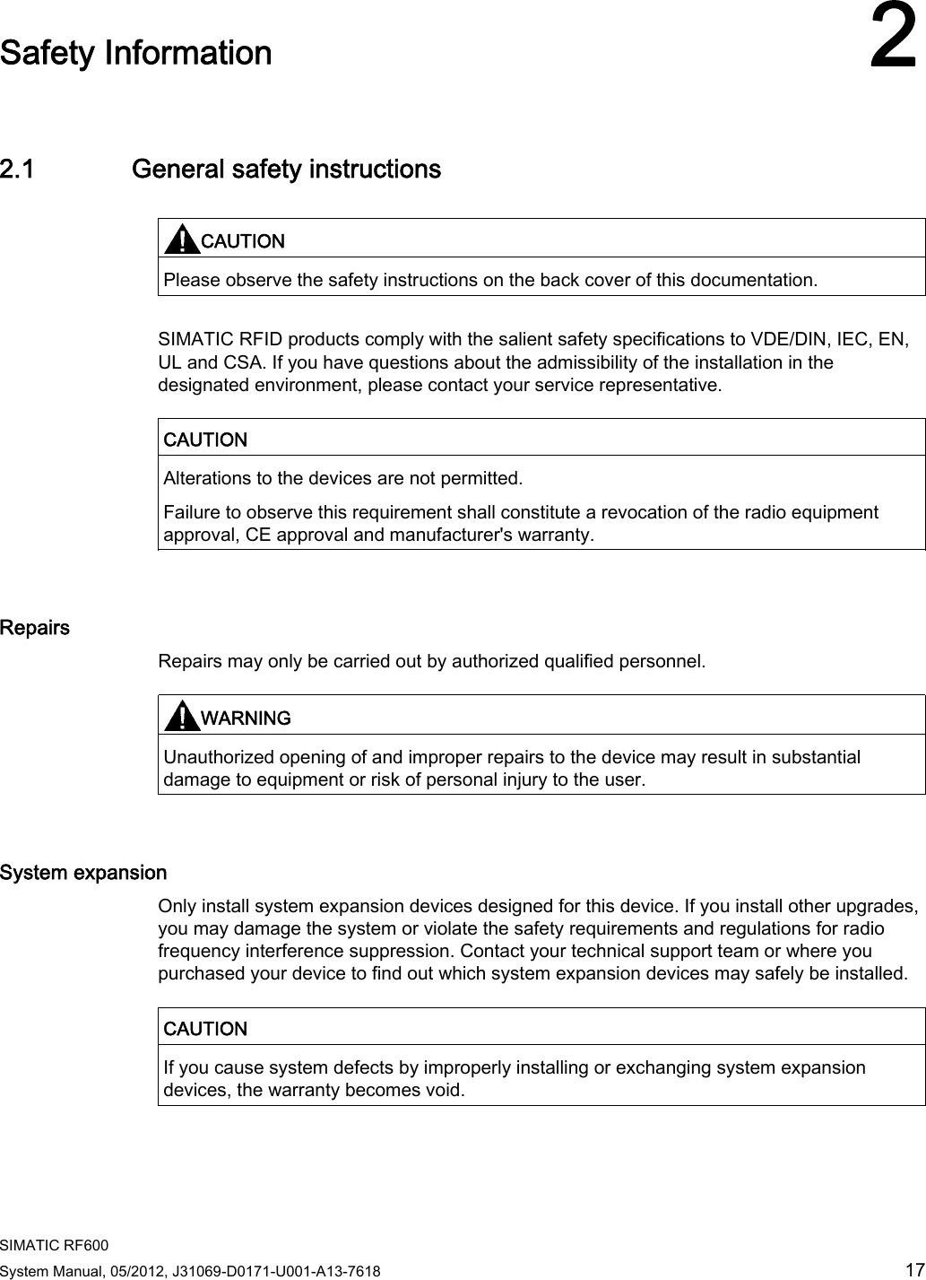
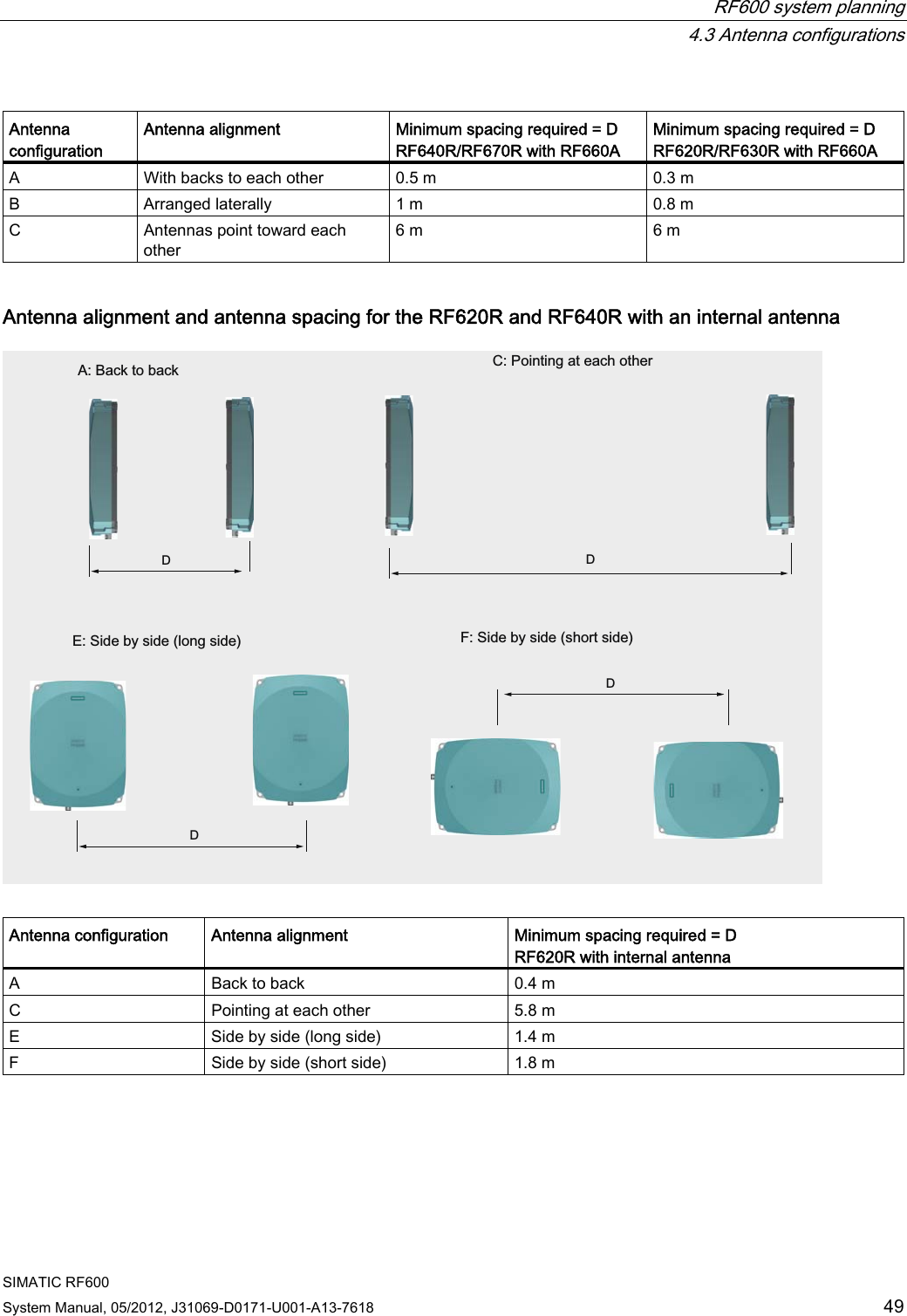
![Safety Information 2.3 Safety distance to transmitter antenna SIMATIC RF600 System Manual, 05/2012, J31069-D0171-U001-A13-7618 21 Note Reduced maximum radiated power with RF620R/RF630R readers The SIMATIC RF620R (ETSI) reader has a maximum radiated power of 0.5 W ERP. The maximum safety distance is therefore 0.12 m. The SIMATIC RF630R (ETSI) reader has a maximum transmitter power of 0.5 W. The radiated power therefore depends on the antenna cable and the type of antenna used, but must not exceed the 2 W ERP. 2.3.3 Minimum distance to antenna in accordance with FCC (USA) Minimum distance to antenna in accordance with FCC (USA) For the maximum permissible radiated power in accordance with FCC (4W EIRP), the "safety distance" d = 0.26 m. This means that personnel should not remain closer than 26 cm to the transmitter antenna for extended periods (several hours without interruption). Remaining within the vicinity of the antenna for brief period, even repeated periods (at a distance < 0.26 m) is harmless to health according to current knowledge. 0204060801001200.1 0.2 0.3 0.4 0.5 0.6 0.7 0.8 0.9 1(OHFWULFDOILHOGVWUHQJWKDWDGLVWDQFHIURPWKH7;DQWHQQDIRU3 :(,53'LVWDQFHP)LHOGVWUHQJWK9P The horizontal line at 41.25 V/m marks the "safety limit value". Distance to transmitter antenna [m] Feld strength [V/m] % of limit value 1 10.9 26 5 2.2 5.3 If the transmit power is set lower than the highest permissible value (4 watts EIRP), the "safety distance" reduces correspondingly. The values for this are as follows:](https://usermanual.wiki/Siemens/RF600R.User-manual-01/User-Guide-1716290-Page-23.png)
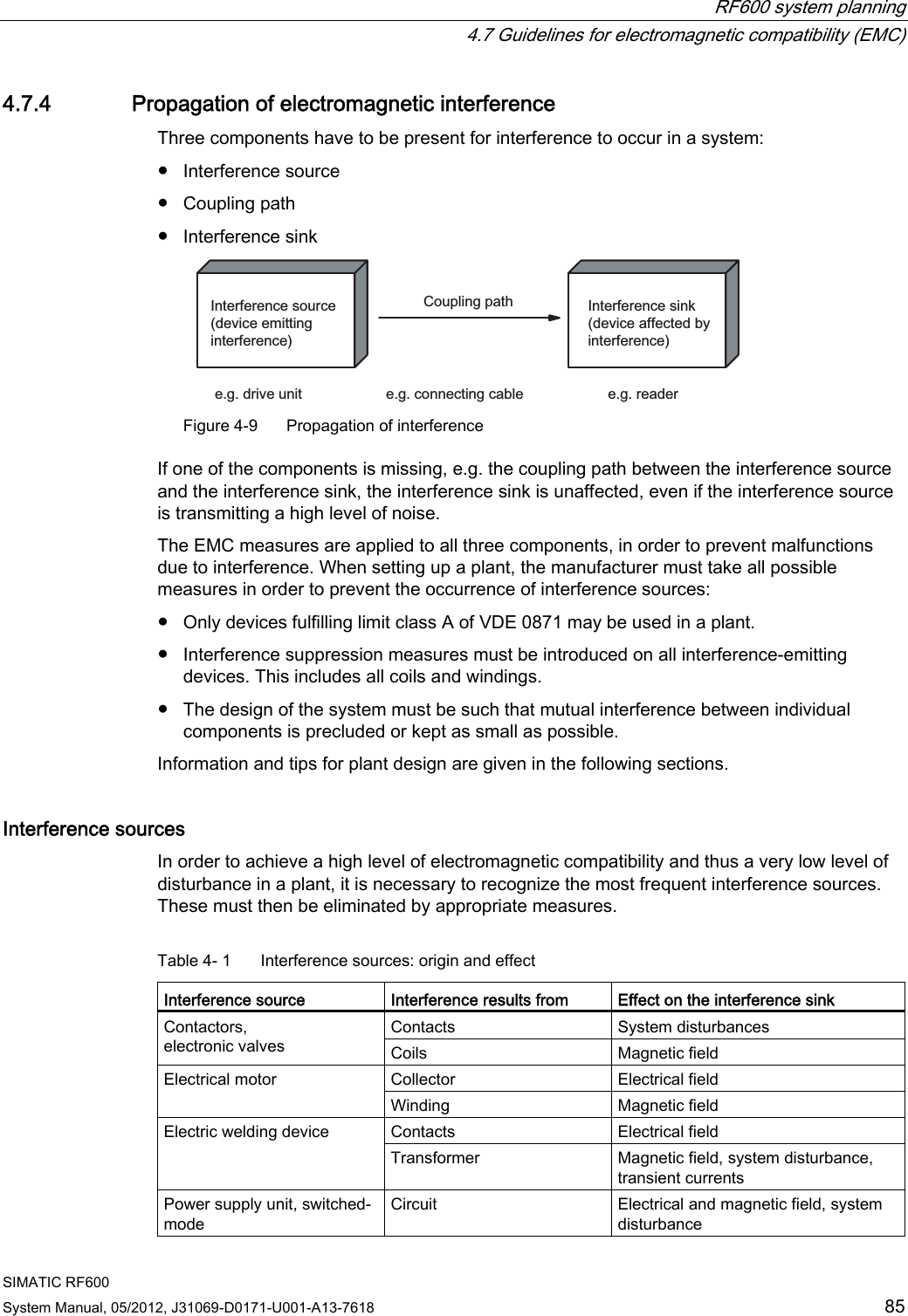
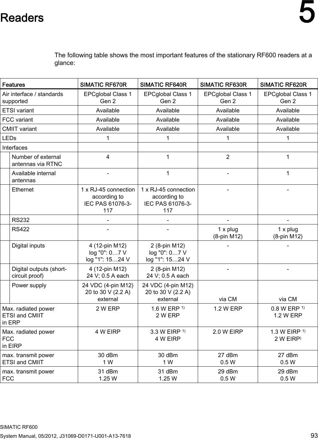
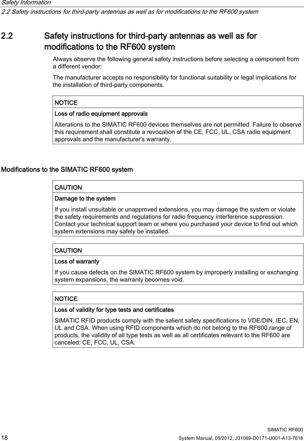
![Safety Information 2.3 Safety distance to transmitter antenna SIMATIC RF600 22 System Manual, 05/2012, J31069-D0171-U001-A13-7618 Radiated power EIRP [W] Safety distance to transmitter antenna [m] 4.0 0.26 <2.5 >0.20 Generally a safety distance of at least 0.2 m must be maintained. Note Reduced maximum radiated power with RF620R/RF630R readers The SIMATIC RF620R (FCC) reader has a maximum transmit power of 0.5 W. Thus the radiated power of 4 W EIRP cannot be exceeded with the internal antenna. The SIMATIC RF630R (FCC) reader has a maximum transmit power of 0.5 W. The radiated power therefore depends on the antenna cable and the type of antenna used, but must not exceed the 4 W EIRP.](https://usermanual.wiki/Siemens/RF600R.User-manual-01/User-Guide-1716290-Page-24.png)
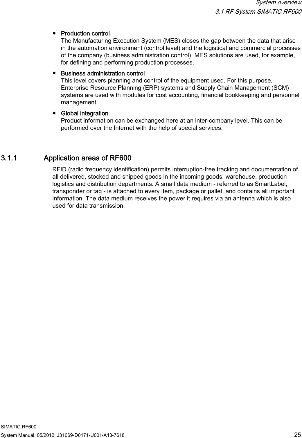
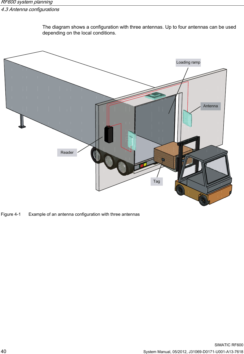
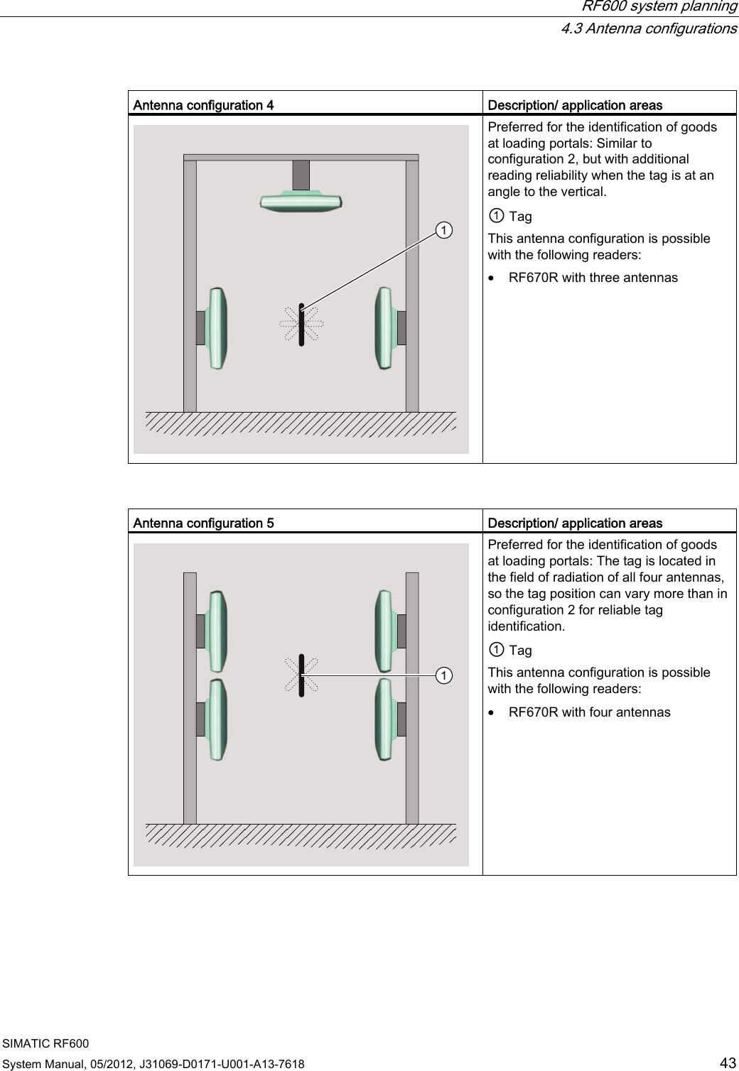
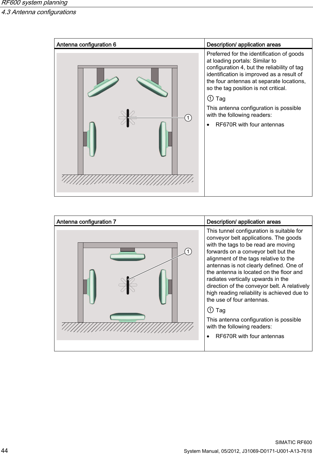
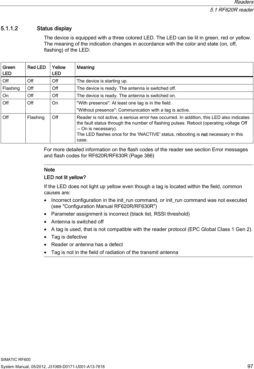
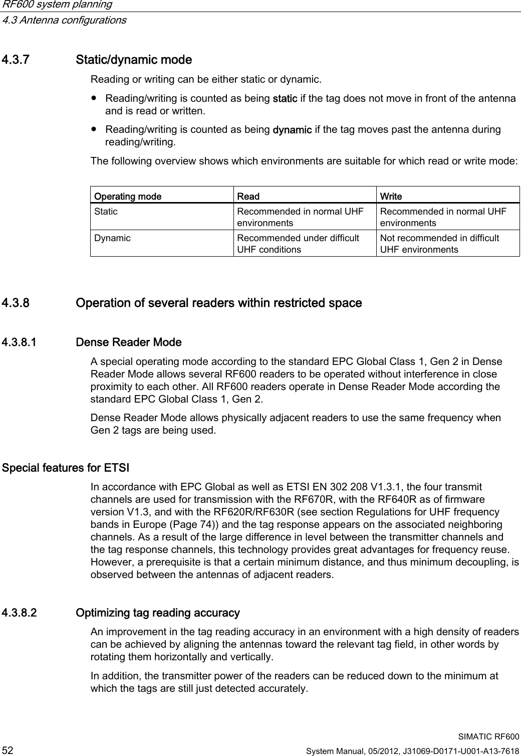
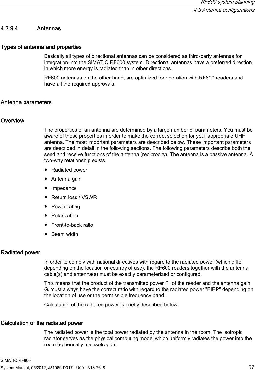
![RF600 system planning 4.3 Antenna configurations SIMATIC RF600 System Manual, 05/2012, J31069-D0171-U001-A13-7618 51 Mode Max. number of tags Min. distance [m] between - two readers with internal antennas - two RF660A antennas Single tag mode: Read 1 3 Single tag mode: Write 1 3 Multitag mode: Read 40 6 Multitag mode: Write 10 6 4.3.6 Read and write range The read/write range between the reader/antenna and the transponder is influenced by the following factors: The reading range depends on Description Transmit power of the reader The higher the transmit power of the reader, the larger the reading range. Tag size and type The larger the tag antenna, the larger the power input area and therefore the larger the reading range. Absorption factor of the materials The higher the absorption of the surrounding material, the smaller the reading range. Production quality of the tag The better the tag has been matched to the operating frequencies during manufacturing, the greater the reading range. Reflection characteristics of the environment In a multiple-reflection environment (e.g., in rooms with reflecting surfaces, machinery, or concrete walls), the reading range can be significantly higher than in a low-reflection environment. Number of transponders in the antenna field The typical ranges always relate to a transponder installed at the maximum possible distance from the antenna. If there is more than one transponder in the antenna field, the distance to all other transponders must be less to allow them to be acquired in the antenna field. The width and height of the antenna field within which its transponders can be arranged at a certain distance from the antenna depend on the following: • The radiated power, • Only reading or reading and writing the transponders (writing requires more power, typically double the power) • The aperture angle (horizontal) • The aperture angle (vertical) You will find detailed information about the reading range of the individual readers in the "Technical specifications" in the sections for the various readers.](https://usermanual.wiki/Siemens/RF600R.User-manual-01/User-Guide-1716290-Page-53.png)
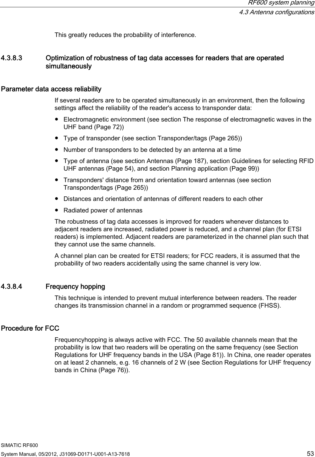
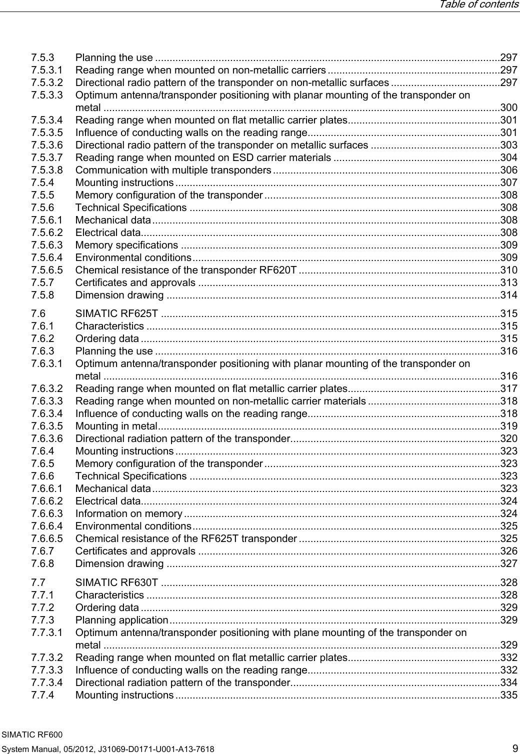
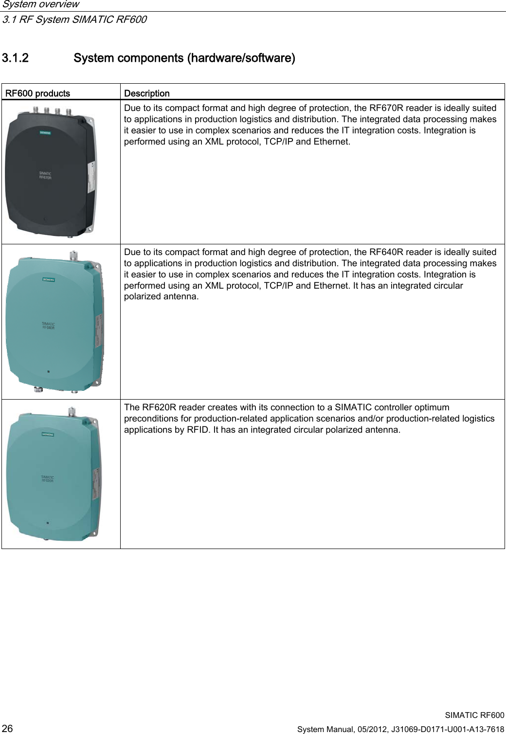
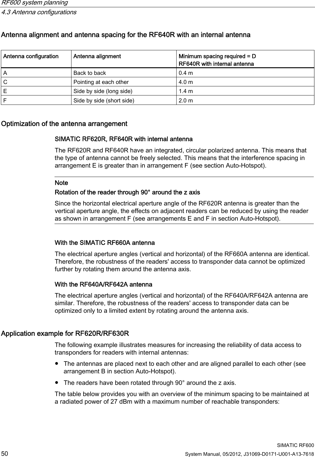
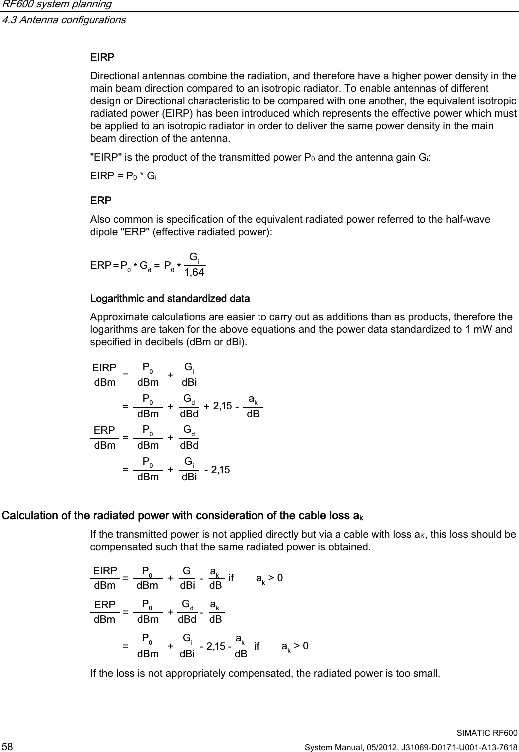
![RF600 system planning 4.3 Antenna configurations SIMATIC RF600 System Manual, 05/2012, J31069-D0171-U001-A13-7618 55 You must be aware of these influencing factors and also consider them if you wish to integrate third-party components such as antennas or cables into the system. These influencing factors are described in more detail in Sections Auto-Hotspot and Auto-Hotspot. 9LHZRIUHDGHU$QWHQQDFRQQHFWLRQV$QWHQQD $QWHQQD$QWHQQDJDLQ,PSHGDQFH5HWXUQORVV96:53RODUL]DWLRQ)URQWWREDFNUDWLR%HDPDQJOH&KDUDFWHULVWLFLPSHGDQFH/HQJWKRIDQWHQQDFDEOH/RVV,PSHGDQFH7UDQVPLWSRZHU5DGLDWHGSRZHU(,53(53 Figure 4-6 Overview of total system and influencing factors When operating the RF600 system, additional influencing factors must also be observed such as minimum spacing between antennas in the room. Environmental conditions CAUTION Damage to the device In line with the application, you must take into consideration the mechanical loads (shock and vibration) as well as environmental demands such as temperature, moisture, UV radiation. The device could be damaged if these factors are not considered.](https://usermanual.wiki/Siemens/RF600R.User-manual-01/User-Guide-1716290-Page-57.png)
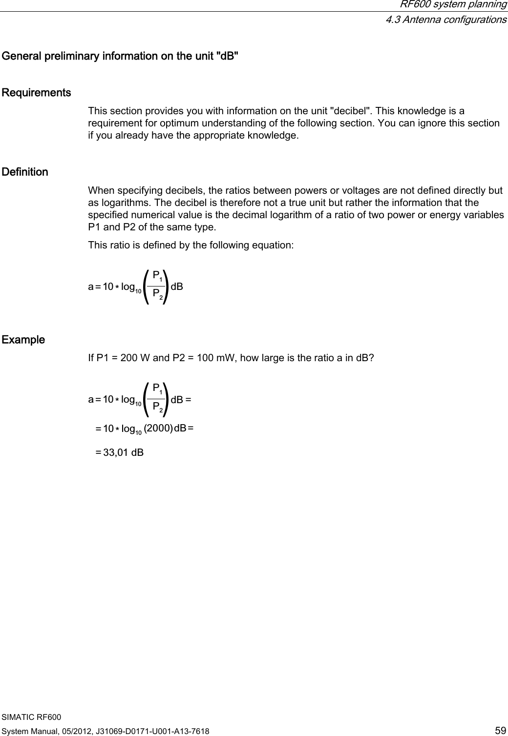
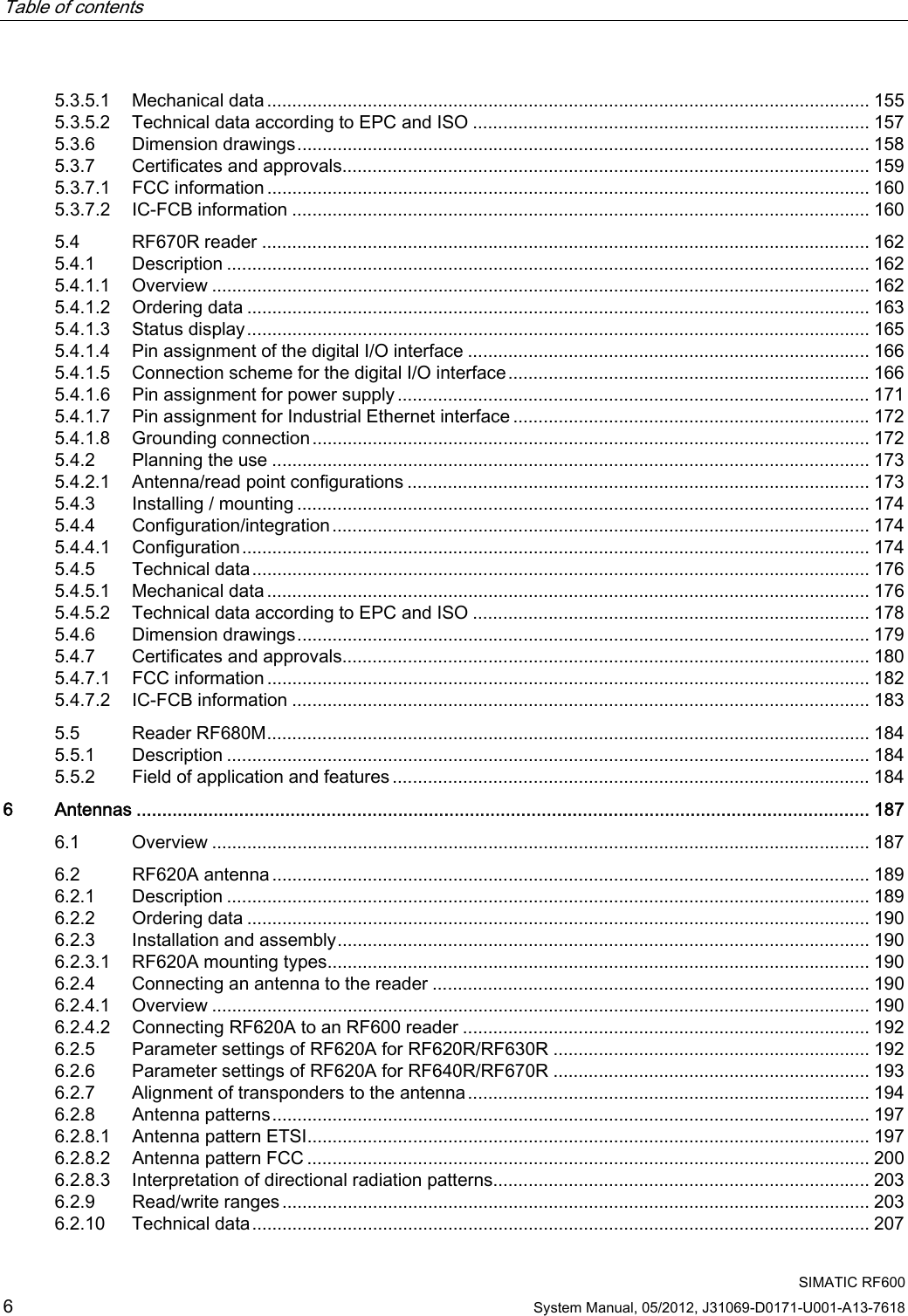
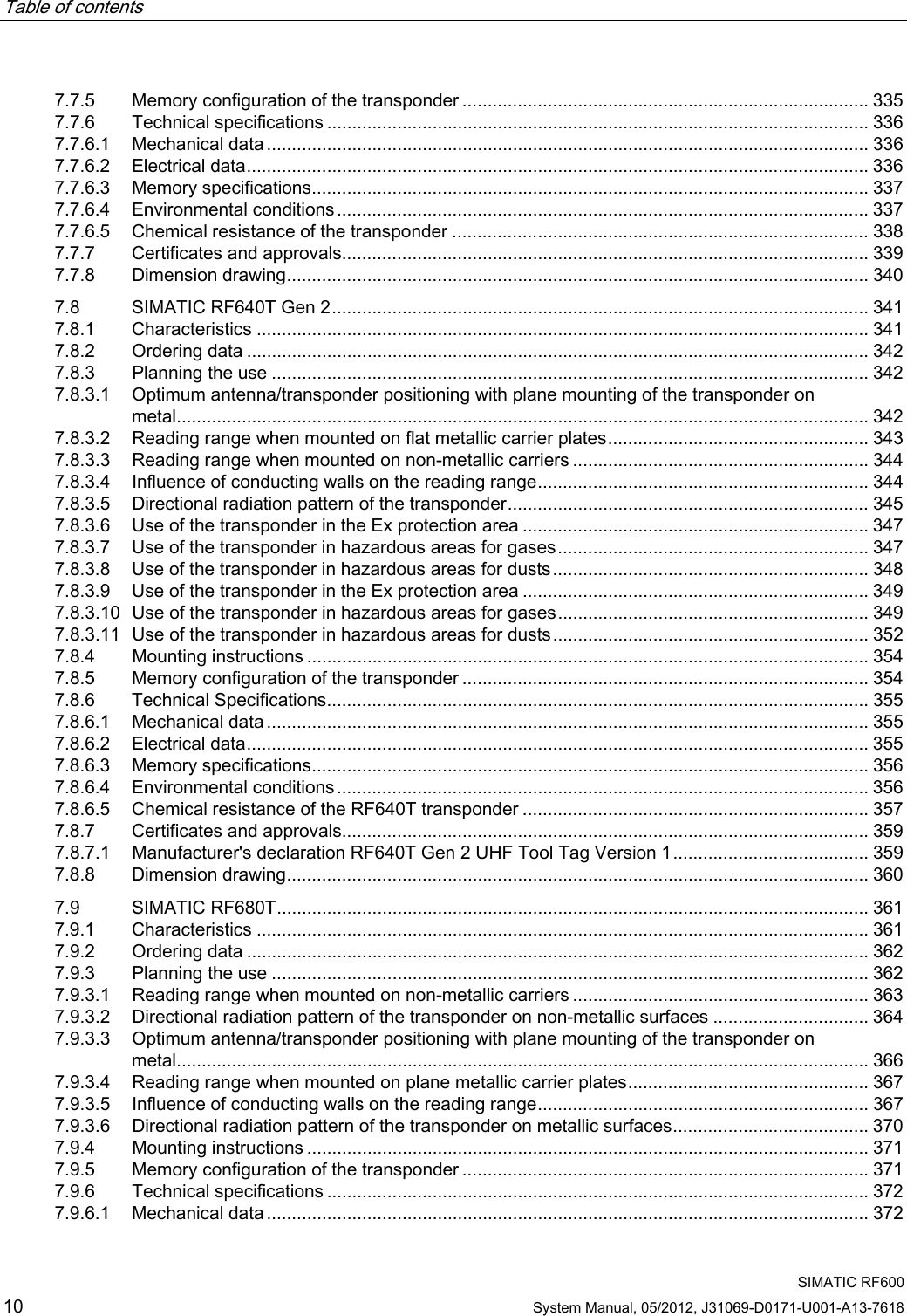
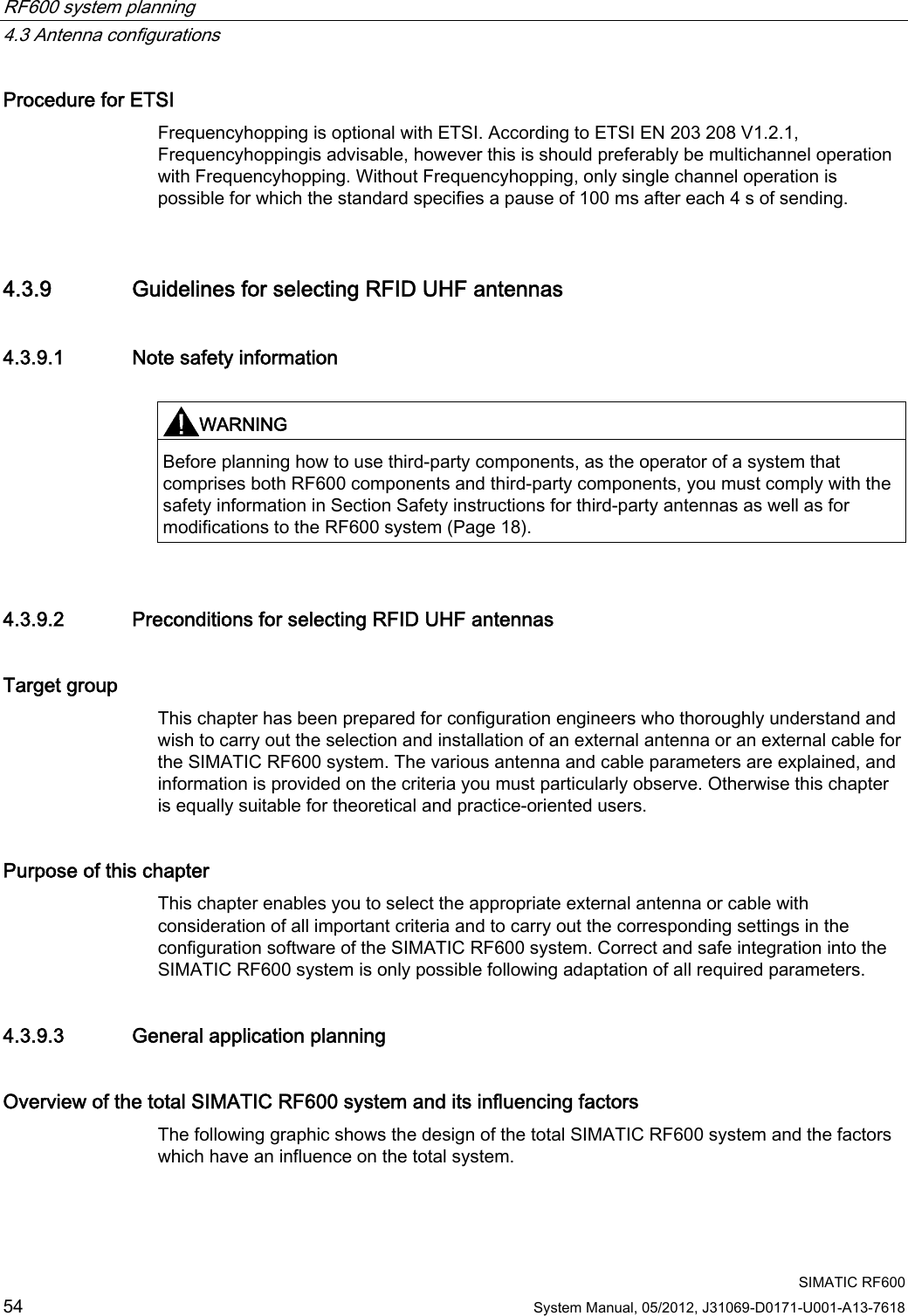
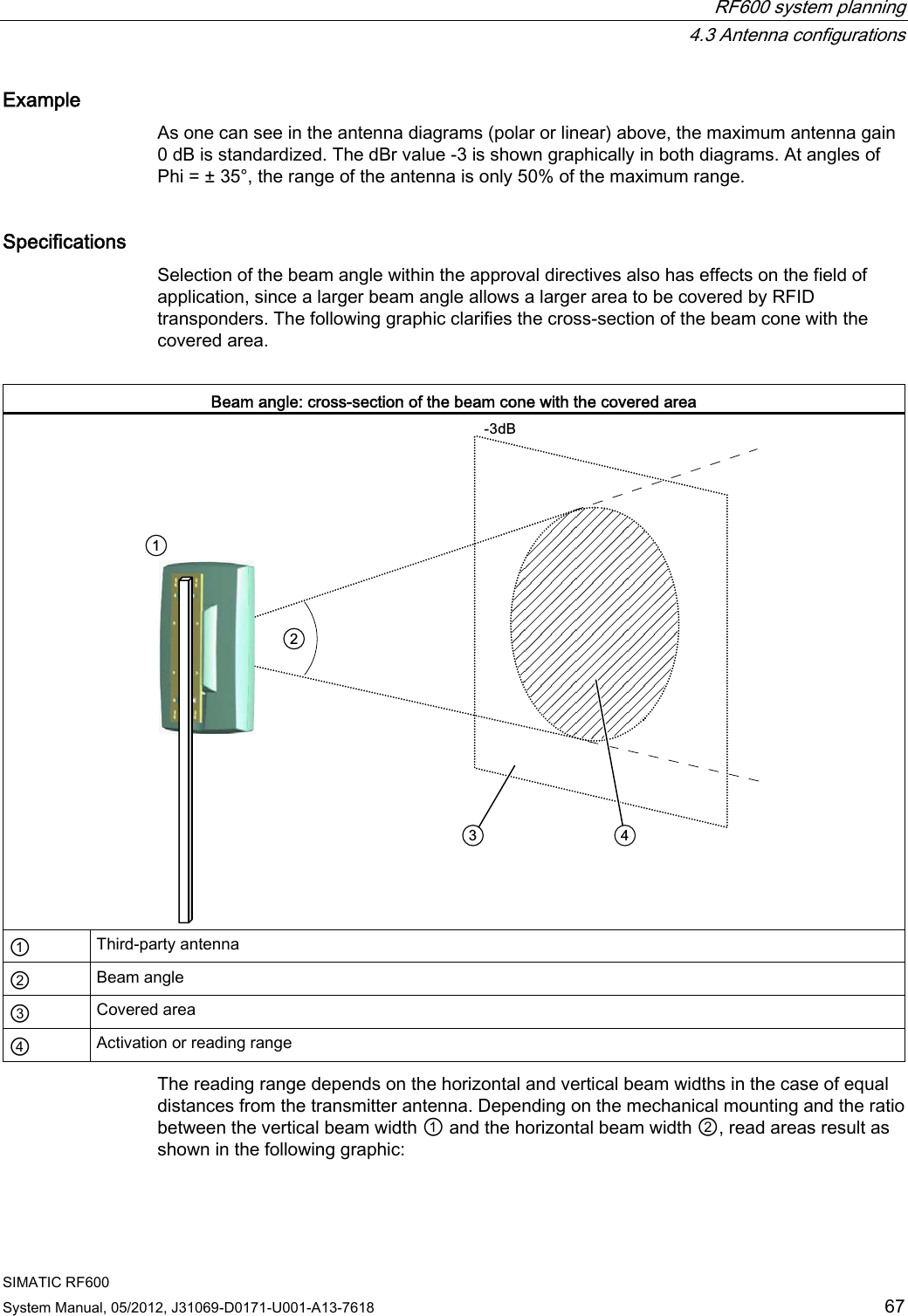
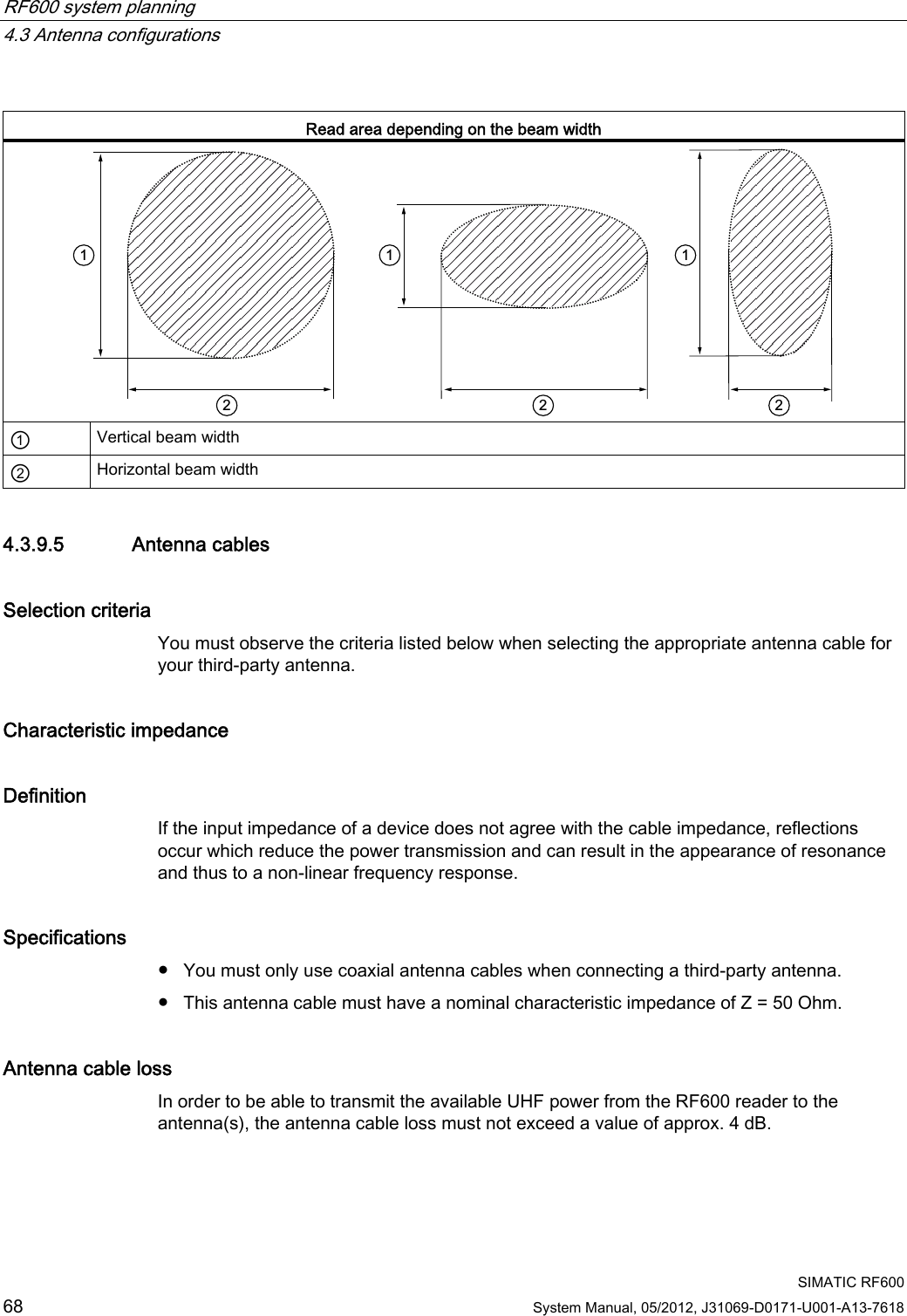
![RF600 system planning 4.3 Antenna configurations SIMATIC RF600 System Manual, 05/2012, J31069-D0171-U001-A13-7618 65 Half-value width Definition A further description of the directional characteristic is the beam width. The beam width is the beam angle at which half the power (-3 dB) is radiated referred to the maximum power. The antenna gain is directly related to the beam width. The higher the antenna gain, the smaller the beam angle. Coupling in ETSI In ETSI EN 302 208 (release version V1.2.1 2008-06), the radiated power is coupled to the beam width, i.e. ● Radiated power 500-2000 mW ERP: beam width ≤ 70 degrees The beam width requirement applies to both the horizontal and vertical planes. The FCC directives do not envisage coupling with the beam width. The following graphics show examples of the directional radiation pattern of an antenna in polar and linear representations for which both the horizontal and vertical planes must be considered. Directional radiation pattern in polar representation 0+] ① Beam width ② Spurious lobe](https://usermanual.wiki/Siemens/RF600R.User-manual-01/User-Guide-1716290-Page-67.png)
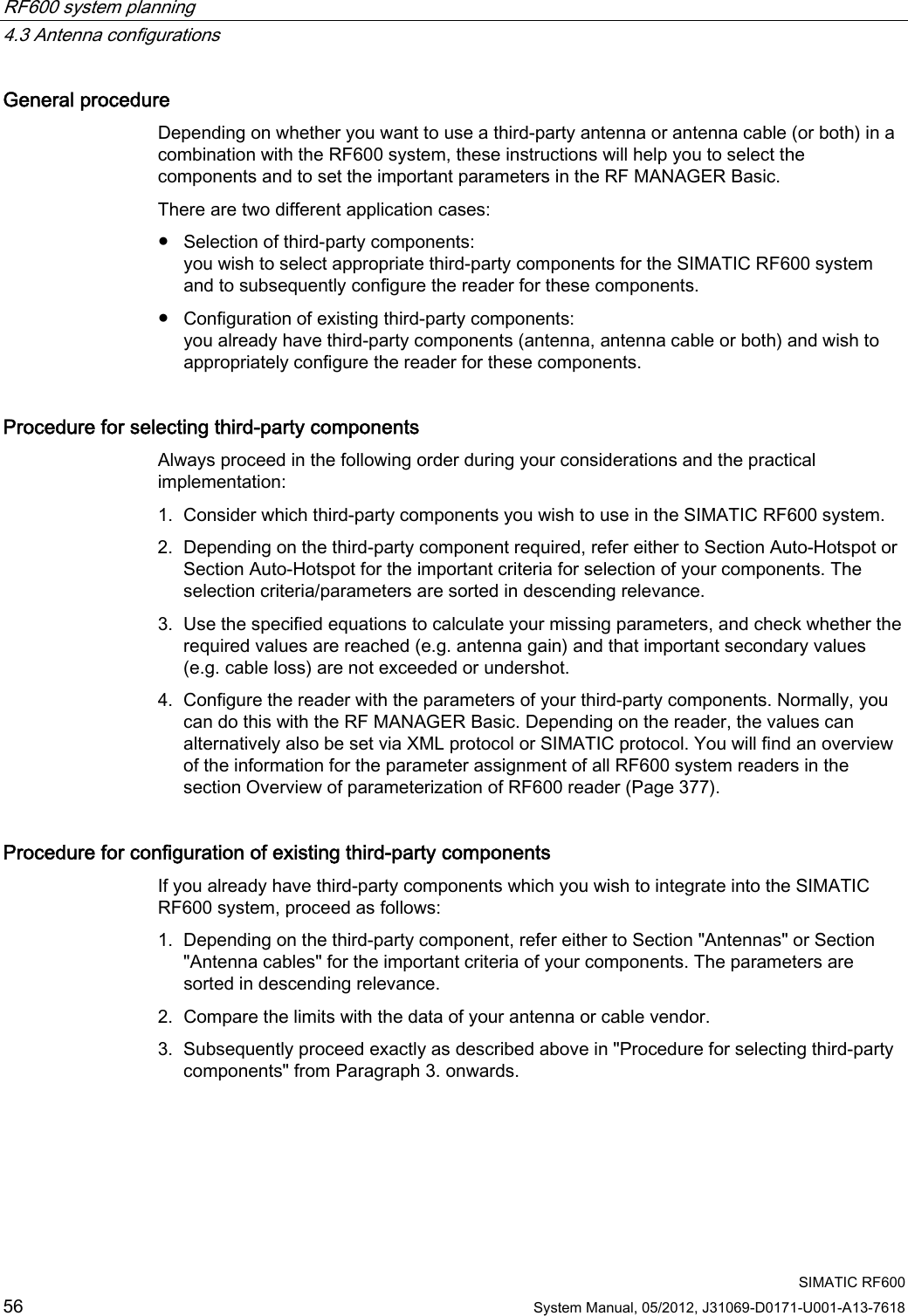
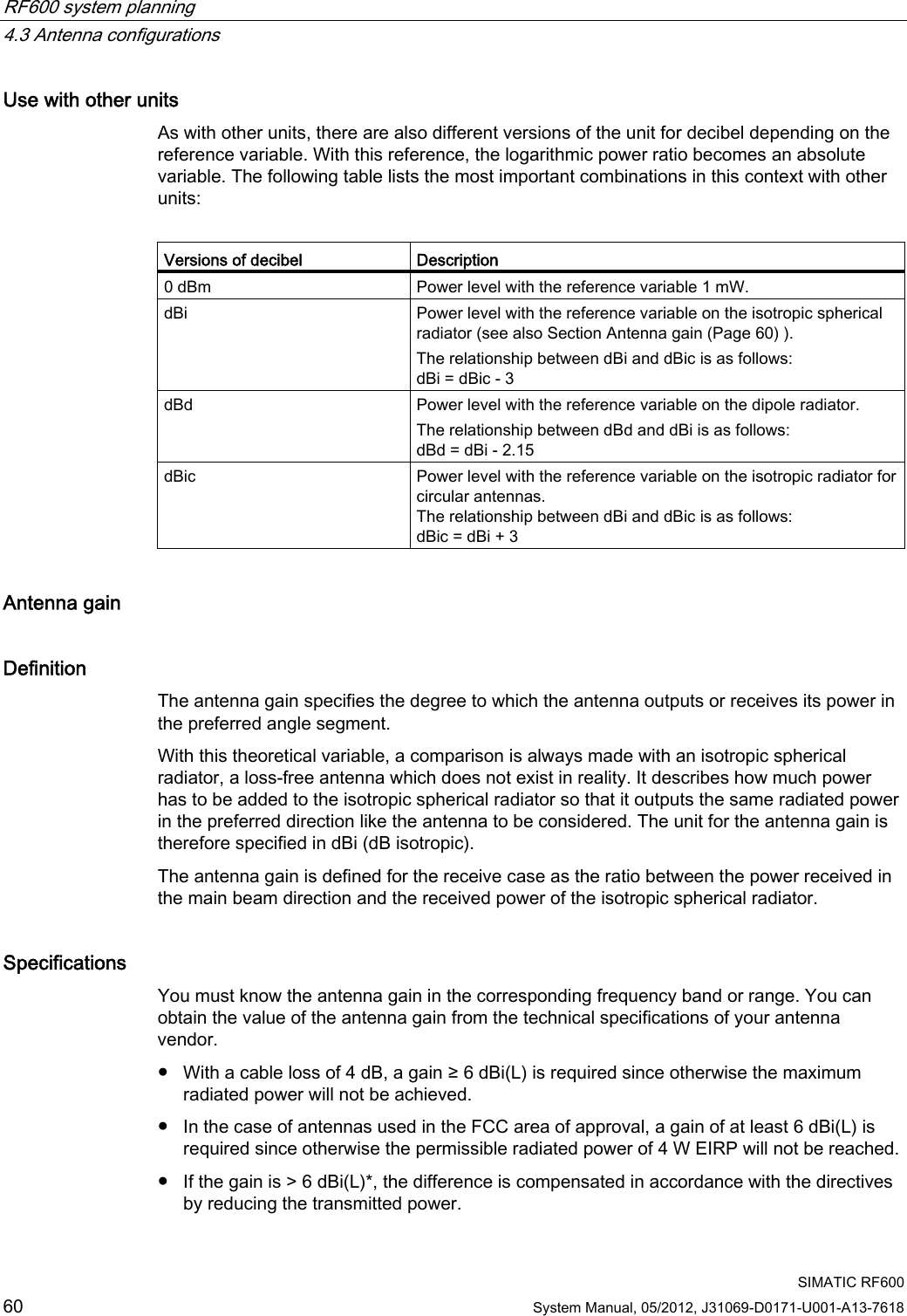
![RF600 system planning 4.3 Antenna configurations SIMATIC RF600 66 System Manual, 05/2012, J31069-D0171-U001-A13-7618 Directional radiation pattern in linear representation 0+]3KLGHJ*DLQG% ① Beam width ② Spurious lobe Interpretation of directional radiation patterns The following overview table will help you with the interpretation of radiation patterns. The table shows which dBi values correspond to which read/write ranges (in %): You can read the radiated power depending on the reference angle from the directional radiation patterns, and thus obtain information on the read/write range with this reference angle with regard to a transponder. The dBr values correspond to the difference between the maximum dBi value and a second dBi value. Deviation from maximum antenna gain [dBr] Read/write range [%] 0 100 -3 70 -6 50 -9 35 -12 25 -15 18 -18 13](https://usermanual.wiki/Siemens/RF600R.User-manual-01/User-Guide-1716290-Page-68.png)
![RF600 system planning 4.6 Regulations applicable to frequency bands SIMATIC RF600 74 System Manual, 05/2012, J31069-D0171-U001-A13-7618 4.6 Regulations applicable to frequency bands The following section describes the regulations for frequency bands which apply in different regions with reference to RFID. It presents the definition of the applicable standard, the precise channel assignments as well as the applicable technique. 4.6.1 Regulations for UHF frequency bands in Europe This revision of the standard EN 302 208 also supports RFID systems with multiple readers operating simultaneously. Within the frequency spectrum, 4 exclusive RFID channels are defined. Regulations for frequency ranges according to EN 302 208 as of V1.2.1 ETSI (European Telecommunications Standards Institute) Specifications according to European standard EN 302 208: ● UHF band: 865 to 868 MHz ● Radiated power: max. 2 W (ERP) ● Channel bandwidth: 200 KHz, channel spacing 600 kHz ● Number of channels: 4 – 865.7 – 866.3 – 866,9 – 867,5 Channel assignment ● The UHF band from 865 to 868 MHz with 4 RFID channels occupies: :(535HDGHUVLJQDO7DJUHVSRQVH0+] 0+]0+] 0+] Validity Note that readers are operated with this setting since November 4, 2008 (publication of the standard in the Official Journal of the European Union).](https://usermanual.wiki/Siemens/RF600R.User-manual-01/User-Guide-1716290-Page-76.png)
![RF600 system planning 4.6 Regulations applicable to frequency bands SIMATIC RF600 System Manual, 05/2012, J31069-D0171-U001-A13-7618 75 4.6.2 Regulations for UHF frequency ranges in Argentina The regulations for the UHF frequency range in Argentina are identical to the Regulations for UHF frequency bands in the USA (Page 81). 4.6.3 Regulations for UHF frequency ranges in Bolivia The regulations for the UHF frequency range in Bolivia are identical to the Regulations for UHF frequency bands in the USA (Page 81). 4.6.4 Regulations for UHF frequency ranges in Brazil FCC subband (Federal Communications Commission) ● UHF band: 515.25 to 527.75 MHz ● Radiated power: max. 4 W (EIRP) ● Number of channels: 26 ● Frequency hopping N+]0+] 0+]FKDQQHOVPD[:(,53 Frequency hopping This technique is intended to prevent mutual interference between readers. The reader changes its transmission channel in a random or programmed sequence (FHSS). 26 available channels mean that the probability is low that two readers will be operating on the same frequency. 4.6.5 Regulations for UHF frequency ranges in Canada Regulations for UHF frequency ranges in Canada are identical to the Regulations for UHF frequency bands in the USA (Page 81).](https://usermanual.wiki/Siemens/RF600R.User-manual-01/User-Guide-1716290-Page-77.png)
![RF600 system planning 4.6 Regulations applicable to frequency bands SIMATIC RF600 76 System Manual, 05/2012, J31069-D0171-U001-A13-7618 4.6.6 Regulations for UHF frequency bands in China Regulations for UHF frequency ranges in China FCC subband (Federal Communications Commission) ● UHF band: 920.125 to 924.875 MHz in 250 kHz channel blocks. ● Radiated power: max. 2 W (ERP) ● Number of channels: 16 to max. 2 W (ERP), 20 to max. 0.1 W (ERP) ● Frequency hopping N+]0+] 0+].DQ¦OHELVPD[:(53.DQ¦OHELVPD[:(53PD[:(53 Channel assignment Sub bands Frequency range Power 920.125 to 920.375 MHz 0.1 W ERP 920.625 to 924.375 MHz 2.0 W ERP : ::0+]0+]0+]N+]0+]924.625 to 924.875 MHz 0.1 W ERP Frequency hopping This technique is intended to prevent mutual interference between readers. The reader changes its transmission channel in a random or programmed sequence (FHSS). With 16 available channels that can be used simultaneously at up to 2000 mW (ERP) and with 20 channels that can be used simultaneously at up to 100 mW, the probability of two readers operating on the same frequency is reduced.](https://usermanual.wiki/Siemens/RF600R.User-manual-01/User-Guide-1716290-Page-78.png)
![RF600 system planning 4.6 Regulations applicable to frequency bands SIMATIC RF600 System Manual, 05/2012, J31069-D0171-U001-A13-7618 77 4.6.7 Regulations for UHF frequency ranges in India This regulation for UHF frequencies in India operates based on the standard ETSI EN 302 208 V1.3.1. It also supports RFID systems with multiple readers operating simultaneously. Within the frequency spectrum, 10 exclusive RFID channels are defined. Regulations for frequency ranges in India Based on European standard ETSI EN 302 208 V1.3.1: ● UHF band: 865 to 866 MHz ● Transmit power: max. 1 W ● Radiated power: < 4 W (EIRP) ● Channel bandwidth: 200 KHz, channel spacing 200 kHz ● Number of channels: 10 – 865,1 – 865,3 – 865,5 – 865,7 – 865,9 – 866,1 – 866,3 – 866,5 – 866,7 – 866,9 Channel assignment ● The UHF band from 865 to 866 MHz is occupied with 10 RFID channels: :0+]0+] 4.6.8 Regulations for UHF frequency ranges in Mexico Regulations for UHF frequency ranges in Mexico are identical to the Regulations for UHF frequency bands in the USA (Page 81).](https://usermanual.wiki/Siemens/RF600R.User-manual-01/User-Guide-1716290-Page-79.png)
![RF600 system planning 4.6 Regulations applicable to frequency bands SIMATIC RF600 78 System Manual, 05/2012, J31069-D0171-U001-A13-7618 4.6.9 Regulations for UHF frequency ranges in Russia This regulation for UHF frequencies in Russia operates based on the standard ETSI EN 302 208 V1.3.1. It also supports RFID systems with multiple readers operating simultaneously. Within the frequency spectrum, 8 exclusive RFID channels are defined. Regulations for frequency ranges according to EN 302 208 V1.3.1 Based on European standard ETSI EN 302 208 V1.3.1: ● UHF band: 866 to 867 MHz ● Radiated power: max. 2 W (ERP) ● Channel bandwidth: 200 KHz, channel spacing 200 kHz ● Number of channels: 8 – 866,1 – 866,3 – 866,5 – 866,7 – 866,9 – 867,1 – 867,3 – 867,5 Channel assignment ● The UHF band from 866 to 867 MHz is occupied with 8 RFID channels: :0+]0+]](https://usermanual.wiki/Siemens/RF600R.User-manual-01/User-Guide-1716290-Page-80.png)
![RF600 system planning 4.6 Regulations applicable to frequency bands SIMATIC RF600 System Manual, 05/2012, J31069-D0171-U001-A13-7618 79 4.6.10 Regulations for UHF frequency bands in Singapore (866-869 MHz band) Regulations applicable to frequency ranges Based on European standard ETSI EN 302 208 V1.3.1: ● UHF band: 866.1 to 867.9 MHz ● Radiated power: max. 0.5 W (ERP) ● Channel bandwidth: 200 kHz ● Number of channels: 10 N+]0+] 0+]FKDQQHOVPD[:(53 NOTICE Exceeding the maximum permitted radiated power of 0.5 W ERP If you want to use this profile with a RF600 reader, during configuration you must make sure tha a maximum of 0.5 W (ERP) is used. Also ensure that you use no channels outside of the specified frequency band. Channel assignment Sub bands Frequency range Power :0+]0+] 866.1 to 867.9 MHz 0.5 W ERP 4.6.11 Regulations for UHF frequency ranges in South Africa Regulations for UHF frequency ranges in South Africa are identical to the Regulations for UHF frequency bands in Europe (Page 74).](https://usermanual.wiki/Siemens/RF600R.User-manual-01/User-Guide-1716290-Page-81.png)
![RF600 system planning 4.6 Regulations applicable to frequency bands SIMATIC RF600 80 System Manual, 05/2012, J31069-D0171-U001-A13-7618 4.6.12 Regulations for UHF frequency ranges in South Korea This regulation for UHF frequency ranges in South Korea operates in the FCC subband. It also supports RFID systems with multiple readers operating simultaneously. Within the frequency spectrum, 16 exclusive RFID channels are defined. The maximum channel dwell time is 400 ms. FCC subband (Federal Communications Commission): ● UHF band: 917.3 to 920.3 MHz ● Radiated power: < 4 W (EIRP) ● Channel bandwidth: 200 kHz ● Number of channels: > 6 (max. 16) Channel assignment ● The UHF band of 917.3 to 920.3 MHz is occupied with up to 16 RFID channels of which at least 7 channels must be used: N+]0+] 0+]FKDQQHOVb:(,53](https://usermanual.wiki/Siemens/RF600R.User-manual-01/User-Guide-1716290-Page-82.png)
![RF600 system planning 4.6 Regulations applicable to frequency bands SIMATIC RF600 System Manual, 05/2012, J31069-D0171-U001-A13-7618 81 4.6.13 Regulations for UHF frequency bands in Thailand FCC (Federal Communications Commission) ● UHF band: 920.25 to 924.75 MHz ● Radiated power: max. 4 W (EIRP) ● Number of channels: 10 ● Frequency hopping N+]0+] 0+]FKDQQHOVPD[:(,53 Frequency hopping This technique is intended to prevent mutual interference between readers. The reader changes its transmission channel in a random or programmed sequence (FHSS). 10 available channels mean that the probability is low that two readers will be operating on the same frequency. 4.6.14 Regulations for UHF frequency bands in the USA FCC (Federal Communications Commission) ● UHF band: 902 to 928 MHz ● Radiated power: max. 4 W (EIRP) ● Number of channels: 50 ● Frequency hopping N+]0+] 0+]FKDQQHOV0D[:(,53b Frequency hopping This technique is intended to prevent mutual interference between readers. The reader changes its transmission channel in a random or programmed sequence (FHSS). 50 available channels mean that the probability is low that two readers will be operating on the same frequency.](https://usermanual.wiki/Siemens/RF600R.User-manual-01/User-Guide-1716290-Page-83.png)