Siemens RF600R RFID UHF Reader User Manual SIMATIC RF600
Siemens AG RFID UHF Reader SIMATIC RF600
UserManual.wiki
>
Siemens
>
RF600R User Manual
>
User manual 04
Contents
1.
User manual 01
2.
User manual 02
3.
User manual 03
4.
User manual 04
5.
User manual 05
User manual 04
Navigation menu
Upload a User Manual
Namespaces
Wiki Guide
HTML
PDF
Info
Views
User Manual
Discussion / Help
Navigation
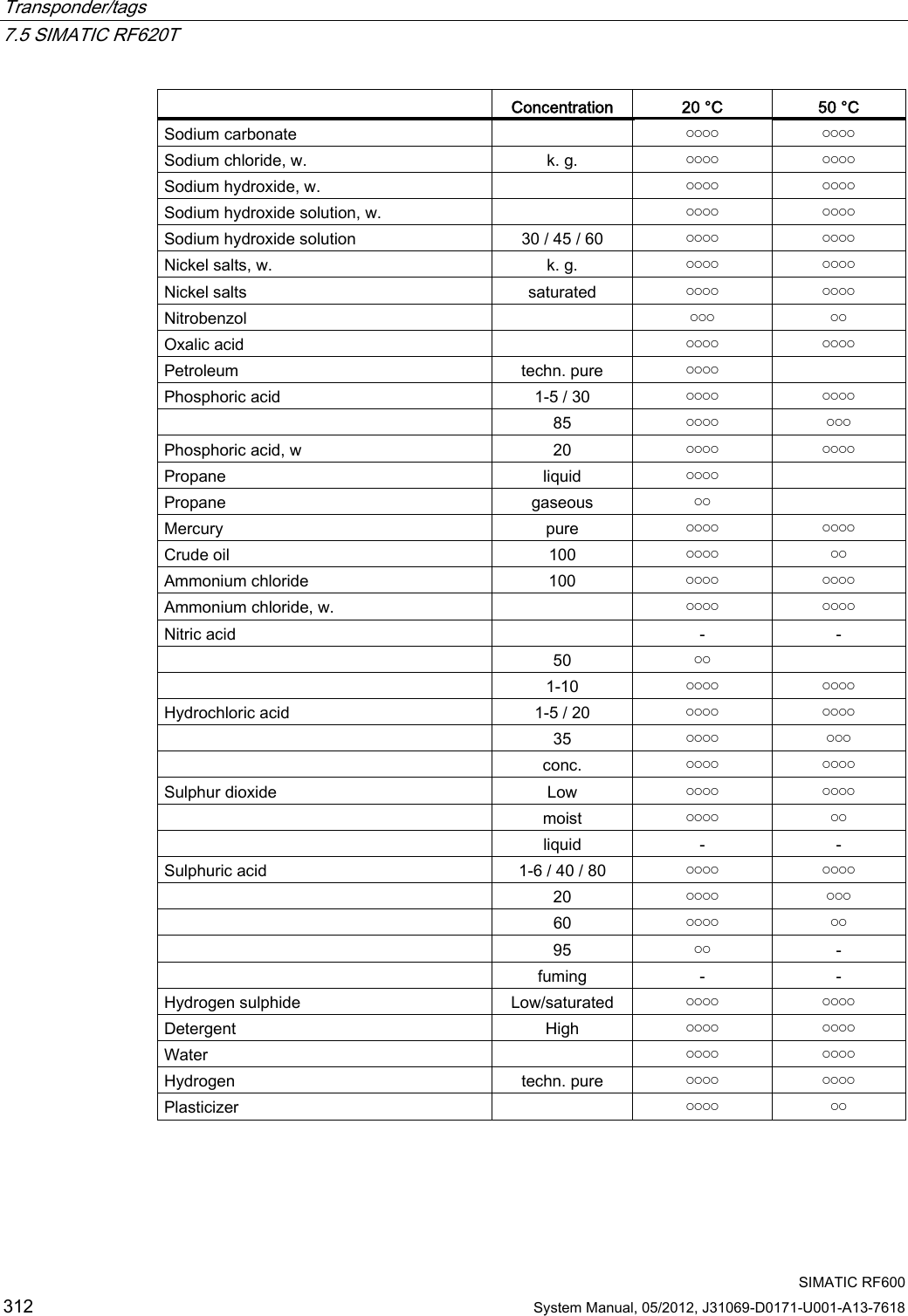
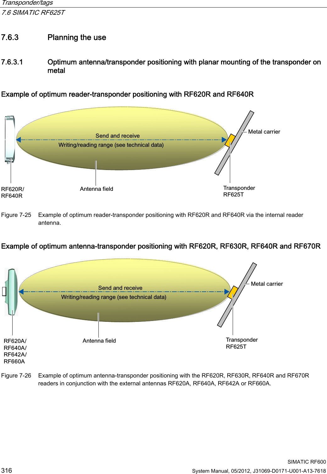
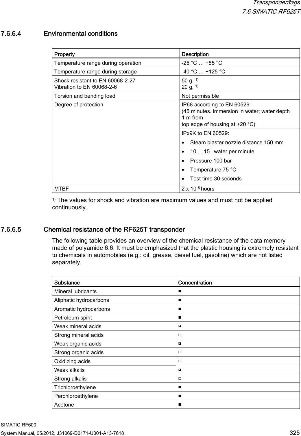
![Transponder/tags 7.6 SIMATIC RF625T SIMATIC RF600 System Manual, 05/2012, J31069-D0171-U001-A13-7618 317 7.6.3.2 Reading range when mounted on flat metallic carrier plates The transponder generally has linear polarization. The polarization axis runs as shown in the diagram below. If the tag is centrically mounted on a flat metal plate, which may either be almost square or circular, it can be aligned in any direction since the transmitting and receiving RF660A antennas operate with circular polarization. 3RODUL]DWLRQD[LV6TXDUH0HWDOFDUULHU&LUFXODUPHWDOFDUULHUSODWHr Figure 7-27 Optimum positioning of the transponder on a (square or circular) metal plate Table 7- 16 Reading range on flat metallic carrier plates Carrier plate material Reading range Metal plate of at least Ø 150 mm 100 % Metal plate Ø 120 mm Approx. 70 % Metal plate Ø 85 mm Approx. 60 % Metal plate Ø 65 mm Approx. 60 % On rectangular carrier plates, the reading range depends on the mounting orientation of the transponder You will find more detailed information on reading ranges in the section "Electrical data (Page 324)".](https://usermanual.wiki/Siemens/RF600R.User-manual-04/User-Guide-1716293-Page-9.png)
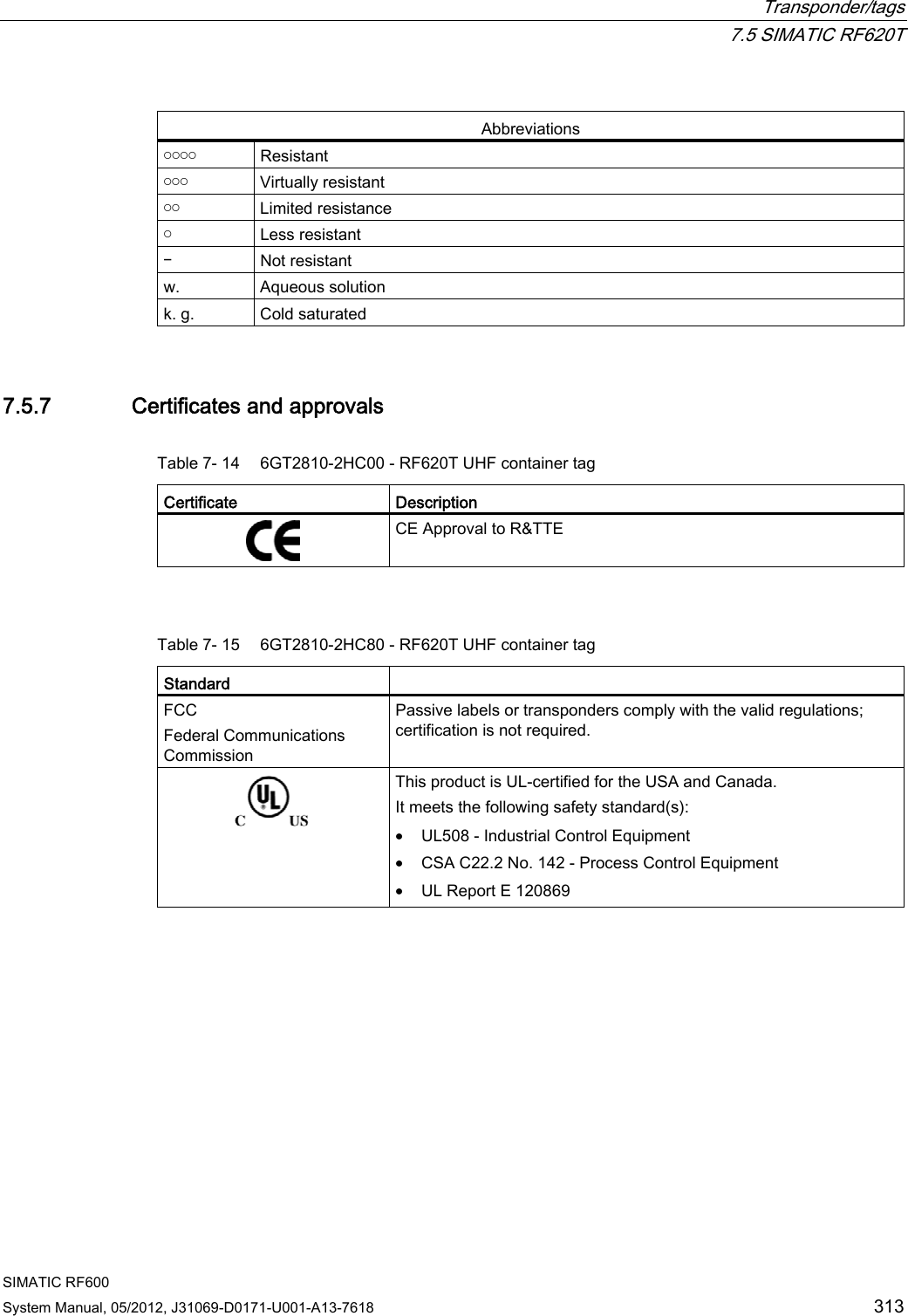
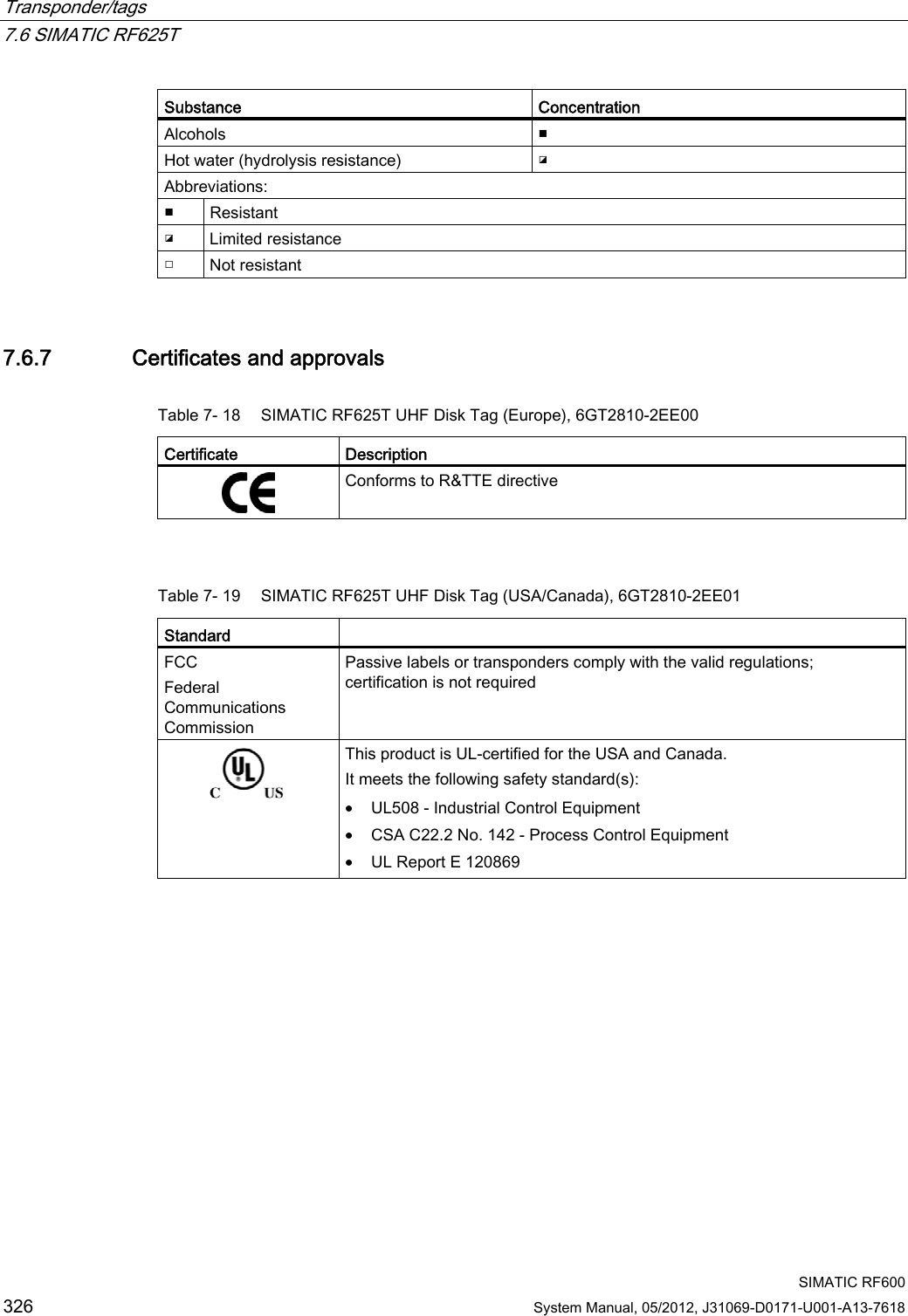
![Transponder/tags 7.6 SIMATIC RF625T SIMATIC RF600 318 System Manual, 05/2012, J31069-D0171-U001-A13-7618 7.6.3.3 Reading range when mounted on non-metallic carrier materials The transponder is generally designed for mounting on metallic objects which provide the conditions for the maximum reading ranges Table 7- 17 Reading range on non-metallic carriers Carrier plate material Reading range 1) Transponder on wooden carrier Approx. 60 % Transponder on plastic carrier Approx. 65 % Transponder on plastic mineral water bottle Approx. 70 % Transponder without base Approx. 50 % 1) The maximum read range of 100 % is achieved by mounting the transponder on a flat metallic carrier with a diameter of at least 150 mm. You will find more detailed information on reading ranges in the section "Electrical data (Page 324)". 7.6.3.4 Influence of conducting walls on the reading range If there are conducting walls or restrictions in the vicinity that could affect the radio field, a distance of approx. 10 cm is recommended. In principle, walls have least influence if the polarization axis is orthogonal to the wall. Reading range: One conducting wall Influence on reading range when positioned against one conducting wall View from above &RQGXFWLQJZDOO3RODUL]DWLRQD[LV0HWDOFDUULHUG Distance d 20 mm 50 mm 100 mm Approx. 100 % Approx. 100 % Approx. 100 % Wall height 20 mm Approx. 100 % Approx. 100 % Approx. 100 % Wall height 50 mm Reading range Approx. 80 % Approx. 100 % Approx. 100 % Wall height 100 mm](https://usermanual.wiki/Siemens/RF600R.User-manual-04/User-Guide-1716293-Page-10.png)
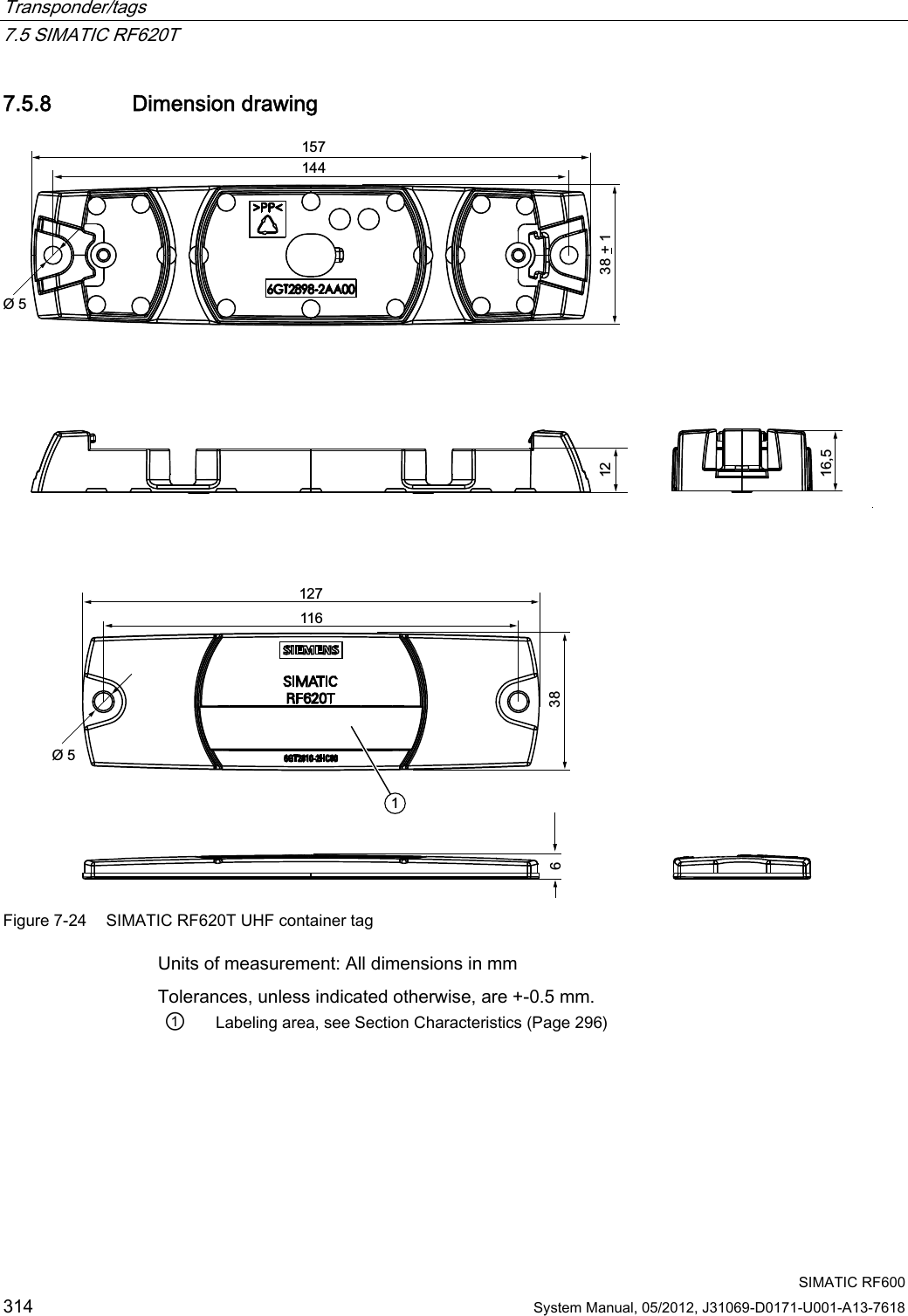
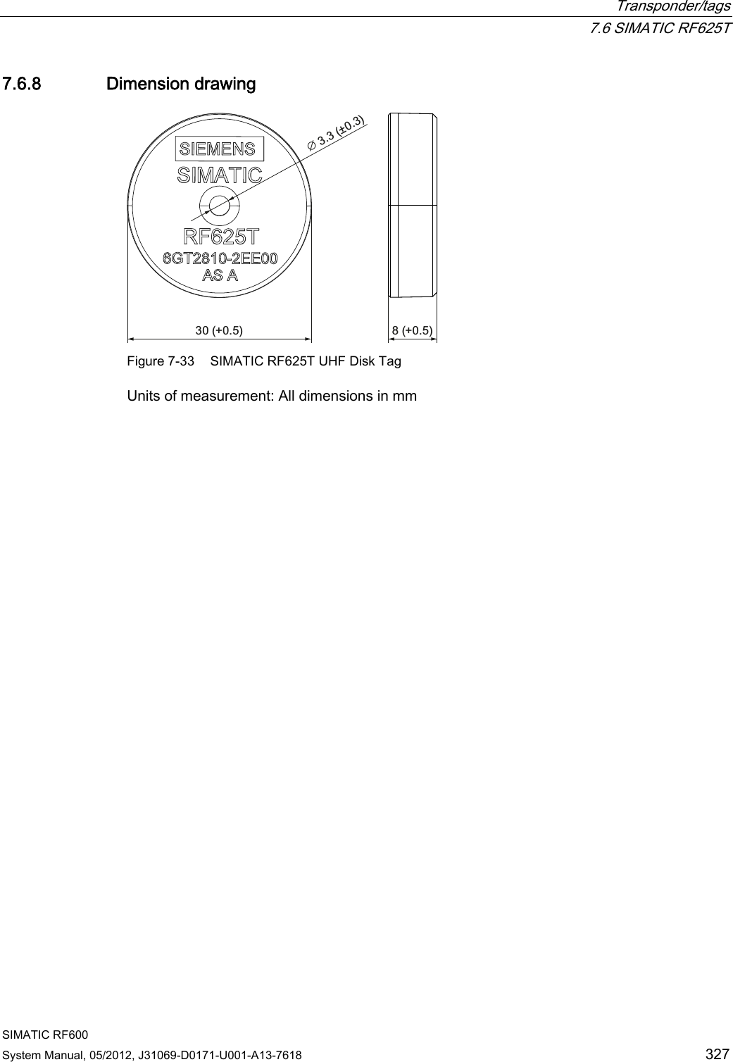
![Transponder/tags 7.6 SIMATIC RF625T SIMATIC RF600 System Manual, 05/2012, J31069-D0171-U001-A13-7618 319 Reading range: Two conducting walls Influence on reading range when positioned against two conducting walls View from above &RQGXFWLQJZDOO&RQGXFWLQJZDOO3RODUL]DWLRQD[LV0HWDOFDUULHUGG Side view 0HWDOFDUULHU&RQGXFWLQJZDOO:DOOKHLJKW&RQGXFWLQJZDOOG Distance d 20 mm 50 mm 100 mm Approx. 70 % Approx. 75 % Approx. 100 % Wall height 20 mm Approx. 70 % Approx. 80 % Approx. 100 % Wall height 50 mm Reading range Approx. 70 % Approx. 40 % Approx. 50 % Wall height 100 mm The values specified in the tables above are guide values. 7.6.3.5 Mounting in metal It is possible to mount the transponder in metal. If there is not enough clearance to the surrounding metal, this reduces the reading range. 7UDQVSRQGHU0HWDOD Clearance (all-round) Reading range 1) a = 5 mm Approx. 50 % a = 10 mm Approx. 70% 1) The read range information applies when the transponder is mounted on a metallic carrier with a diameter of at least 150 mm. Figure 7-28 Flush-mounting of RF625T in metal](https://usermanual.wiki/Siemens/RF600R.User-manual-04/User-Guide-1716293-Page-11.png)
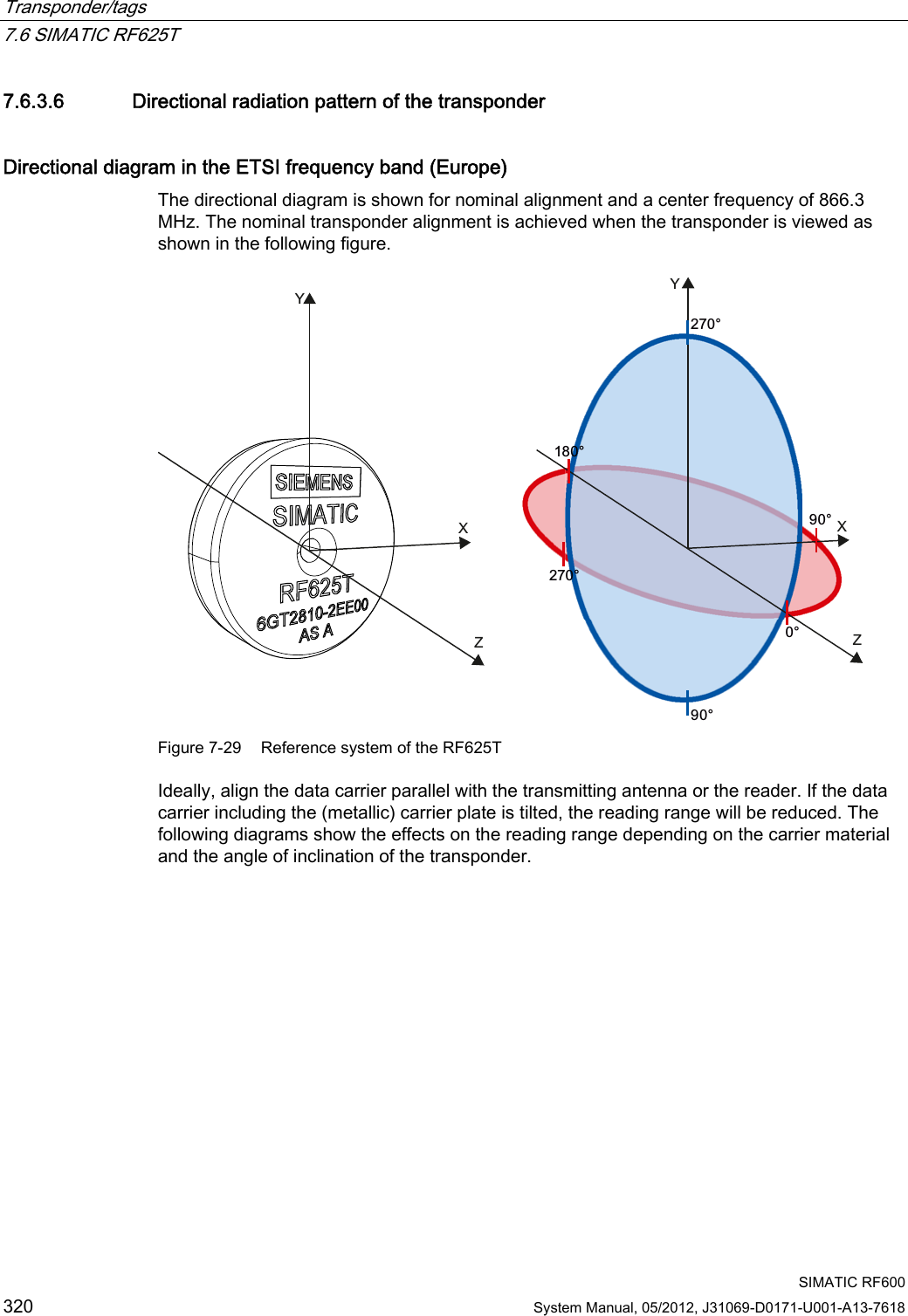
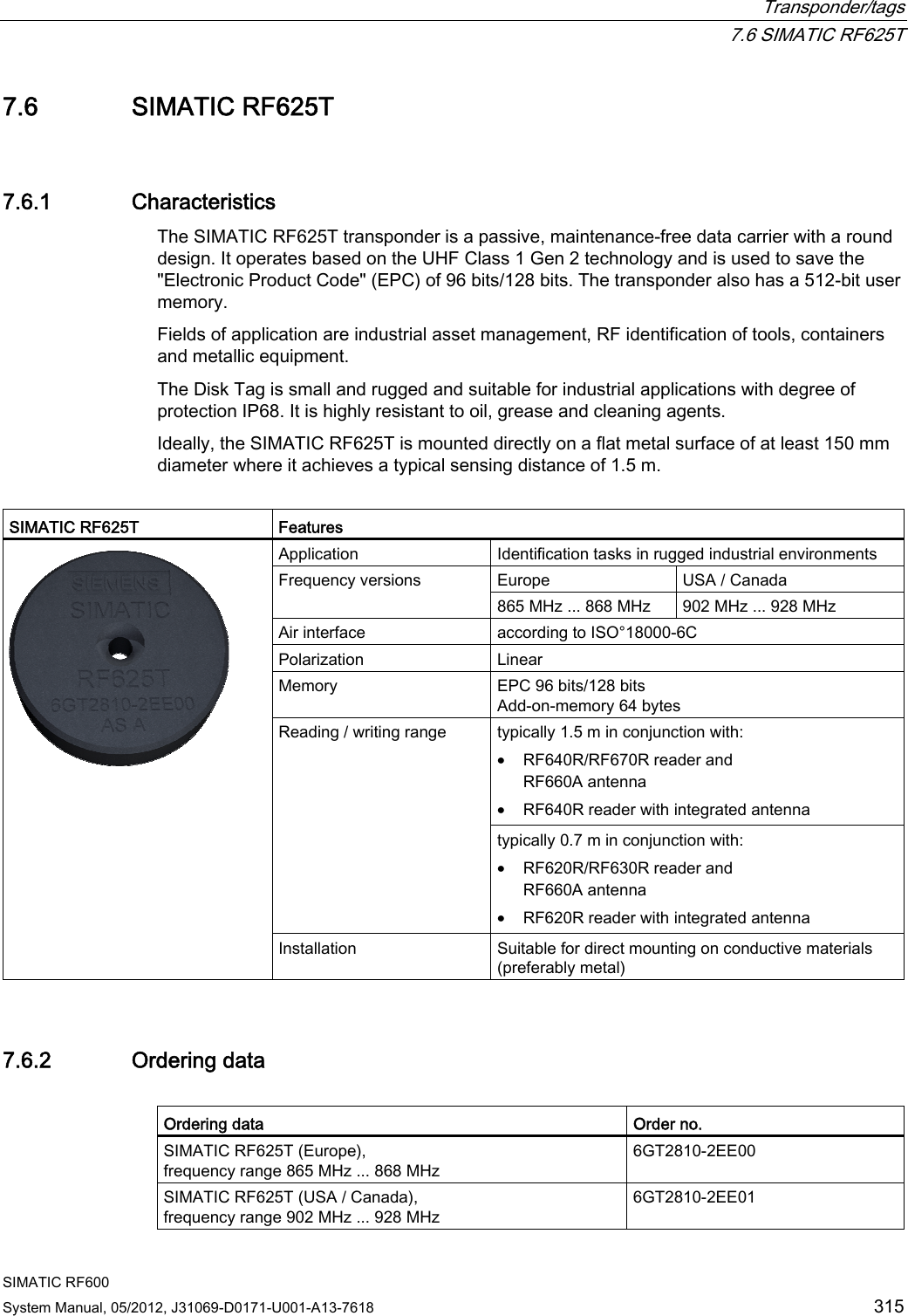
![Transponder/tags 7.6 SIMATIC RF625T SIMATIC RF600 System Manual, 05/2012, J31069-D0171-U001-A13-7618 321 Directional characteristics of the transponder when mounted on a metallic carrier 9HUWLFDO+RUL]RQWDO $QJOHGHJUHHV5HDGLQJUDQJHSHUFHQWDJH Figure 7-30 Directional characteristics of the RF625T on a metallic carrier depending on the angle of inclination in a vertical or horizontal direction](https://usermanual.wiki/Siemens/RF600R.User-manual-04/User-Guide-1716293-Page-13.png)
![Transponder/tags 7.6 SIMATIC RF625T SIMATIC RF600 322 System Manual, 05/2012, J31069-D0171-U001-A13-7618 Directional characteristics of the transponder when mounted on a non-metallic carrier $QJOHGHJUHHV9HUWLFDO+RUL]RQWDO5HDGLQJUDQJHSHUFHQWDJH Figure 7-31 Directional characteristics of the RF625T on a non-metallic carrier depending on the angle of inclination in a vertical or horizontal direction](https://usermanual.wiki/Siemens/RF600R.User-manual-04/User-Guide-1716293-Page-14.png)
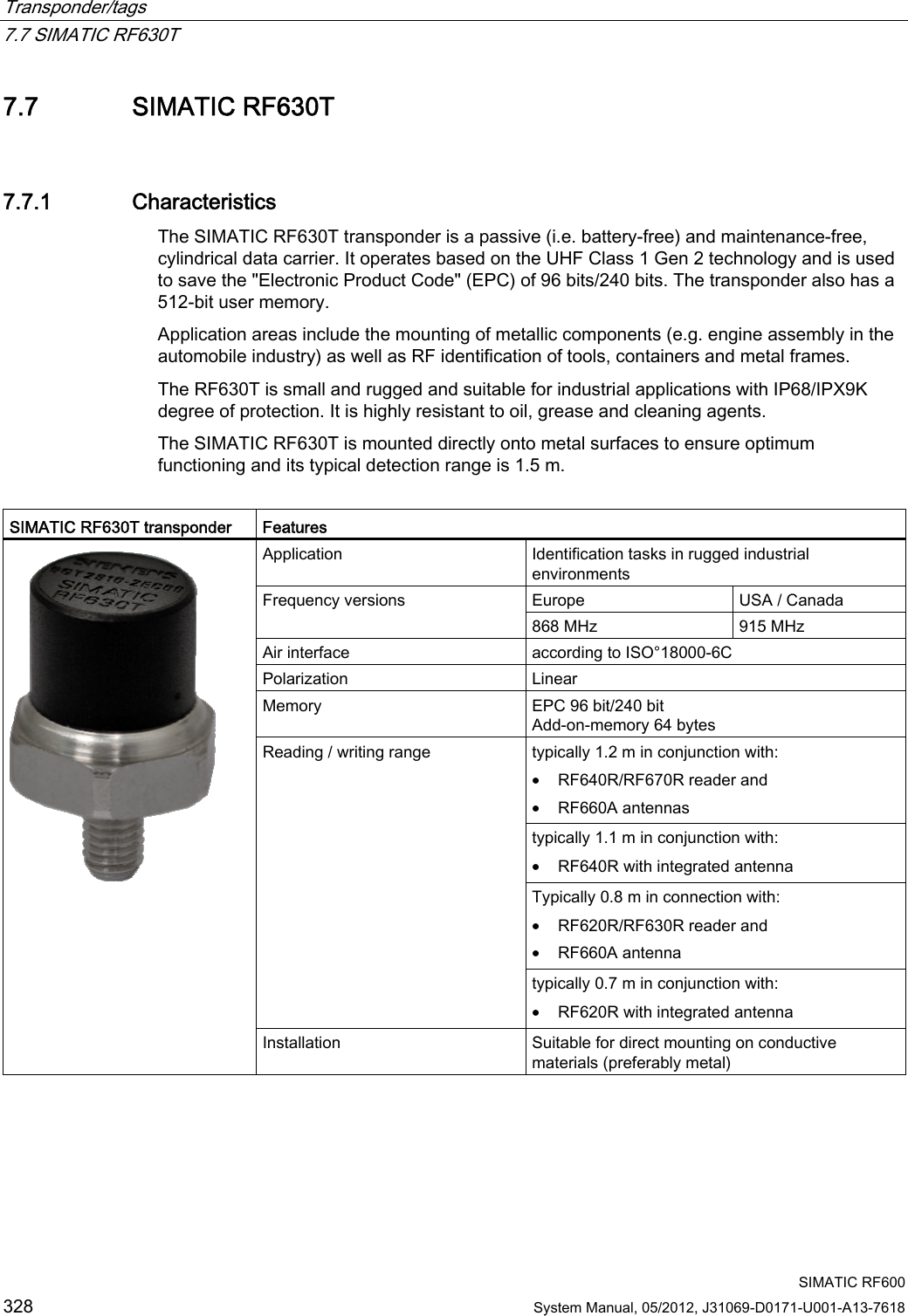
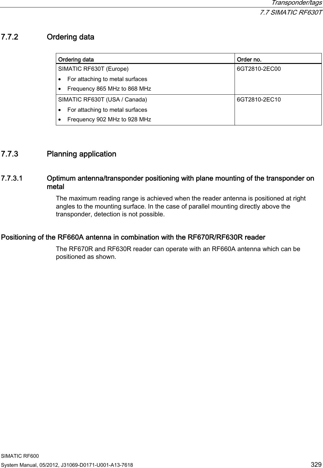
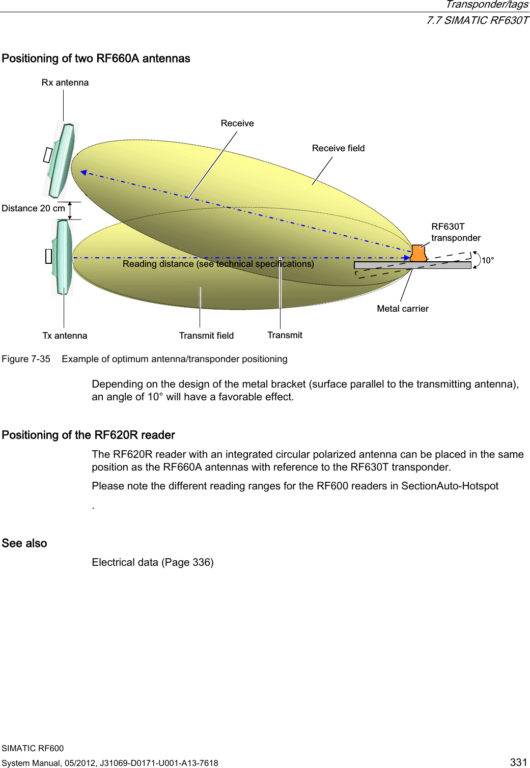
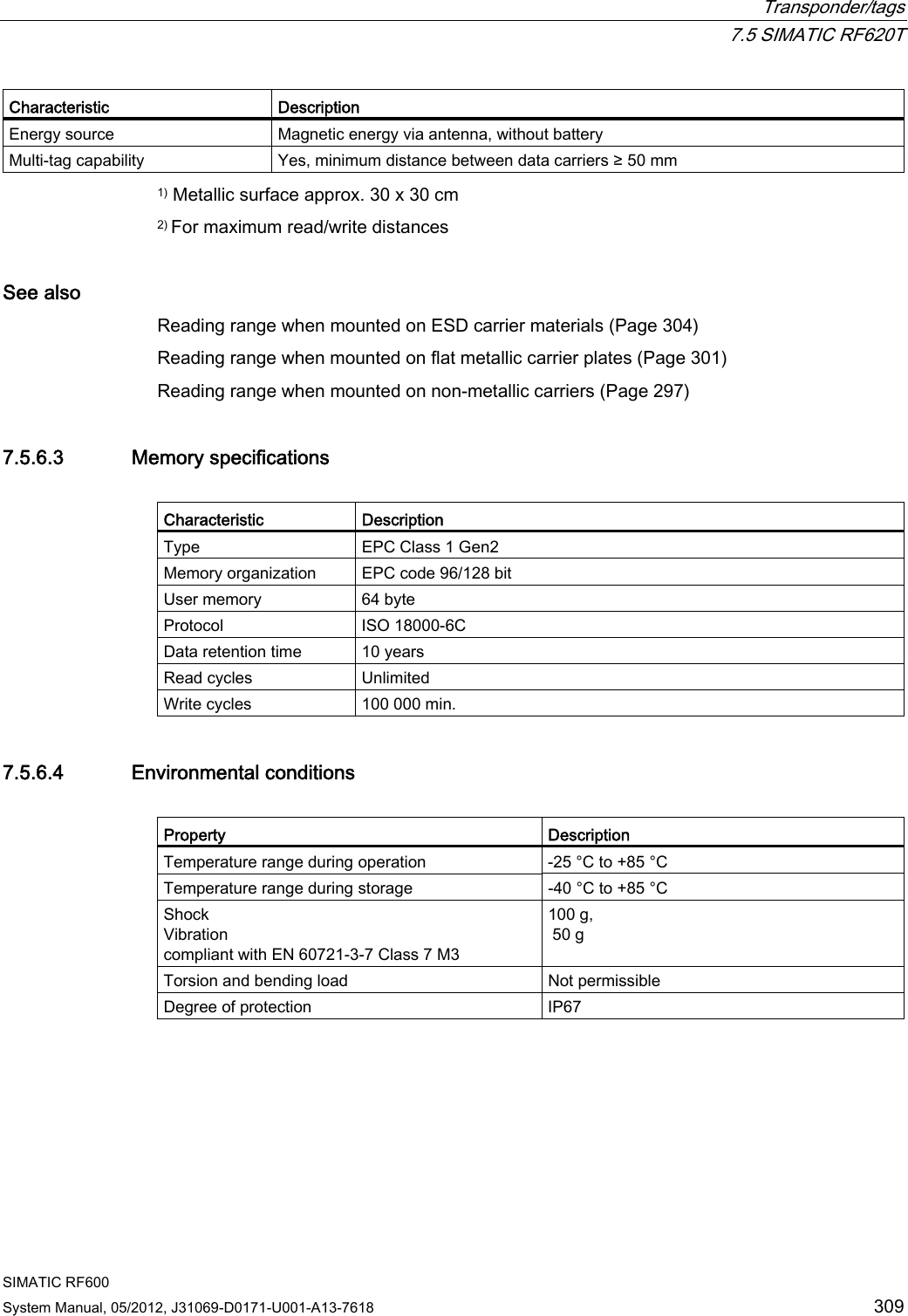
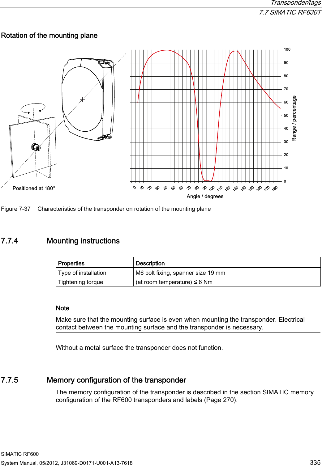
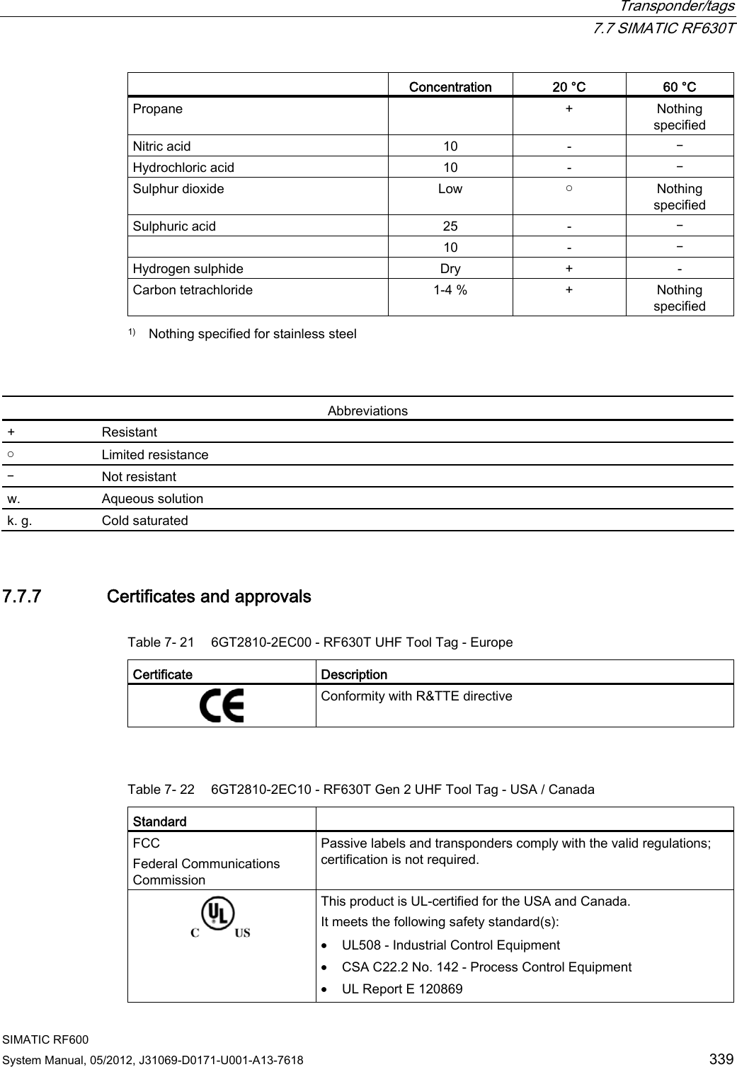
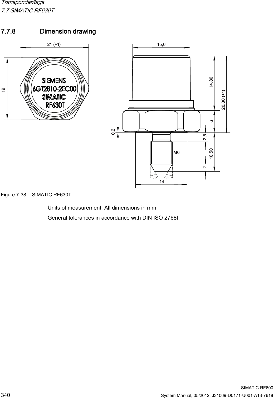
![Transponder/tags 7.7 SIMATIC RF630T SIMATIC RF600 332 System Manual, 05/2012, J31069-D0171-U001-A13-7618 7.7.3.2 Reading range when mounted on flat metallic carrier plates The transponder generally has linear polarization. The polarization axis runs as shown in the diagram below. If the tag is centrally mounted on a flat metal plate, which may either be almost square or circular, it can be aligned in any direction since the transmitting and receiving RF660A antennas operate with circular polarization. 3RODUL]DWLRQD[LVrr5)$ Figure 7-36 Optimum positioning of the transponder on a (square or circular) metal plate Table 7- 20 Reading range on flat metallic carrier plates Carrier plate material Reading range Metal plate of at least Ø 300 mm 100 % Metal plate Ø 150 mm Approx. 75 % Metal plate Ø 120 mm Approx. 50 % Metal plate Ø 85 mm Approx. 40 % On rectangular carrier plates, the reading distance depends on the mounting orientation of the transponder 7.7.3.3 Influence of conducting walls on the reading range If there are conducting walls or restrictions in the vicinity that could shade the radio field, a distance of approx. 10 cm is recommended between the transponder and the wall. In principle, walls have least influence if the polarization axis is vertical to the conducting wall.](https://usermanual.wiki/Siemens/RF600R.User-manual-04/User-Guide-1716293-Page-24.png)
![Transponder/tags 7.7 SIMATIC RF630T SIMATIC RF600 System Manual, 05/2012, J31069-D0171-U001-A13-7618 333 Reading range: One conducting wall Influence on reading range when positioned against one conducting wall &RQGXFWLQJZDOOG Top view Distance d 20 mm 50 mm 100 mm Approx. 40 % Approx. 40 % Approx. 90 % Wall height 20 mm Approx. 40 % Approx. 90 % Approx. 90 % Wall height 50 mm Reading range Approx. 40 % Approx. 40 % Approx. 90 % Wall height 100 mm Reading range: Two conducting walls Influence on reading range when positioned against two conducting walls &RQGXFWLQJZDOO&RQGXFWLQJZDOO0HWDOFDUULHUGG G3RODUL]DWLRQD[LV0HWDOFDUULHU&RQGXFWLQJZDOO:DOOKHLJKW Side view Distance d 20 mm 50 mm 100 mm Approx. 90 % Approx. 90 % Approx. 90 % Wall height 20 mm Approx. 25 % Approx. 90 % Approx. 90 % Wall height 50 mm Reading range Approx. 25 % Approx. 90 % Approx. 90 % Wall height 100 mm The values specified in the tables above must be complied with.](https://usermanual.wiki/Siemens/RF600R.User-manual-04/User-Guide-1716293-Page-25.png)
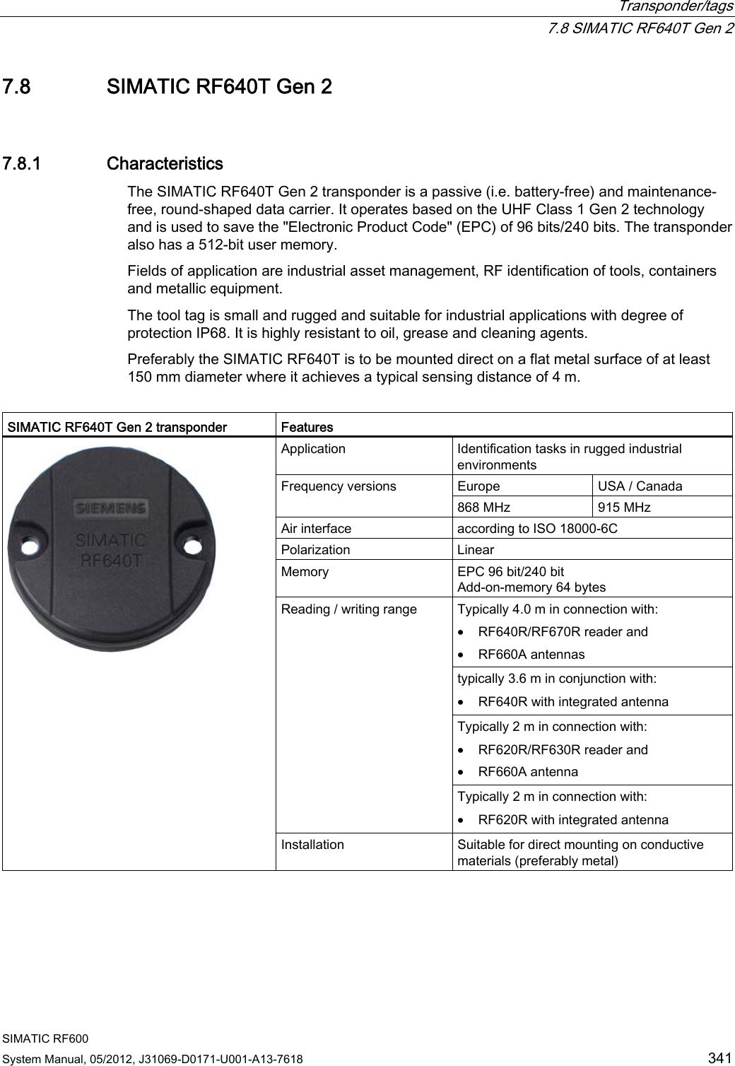
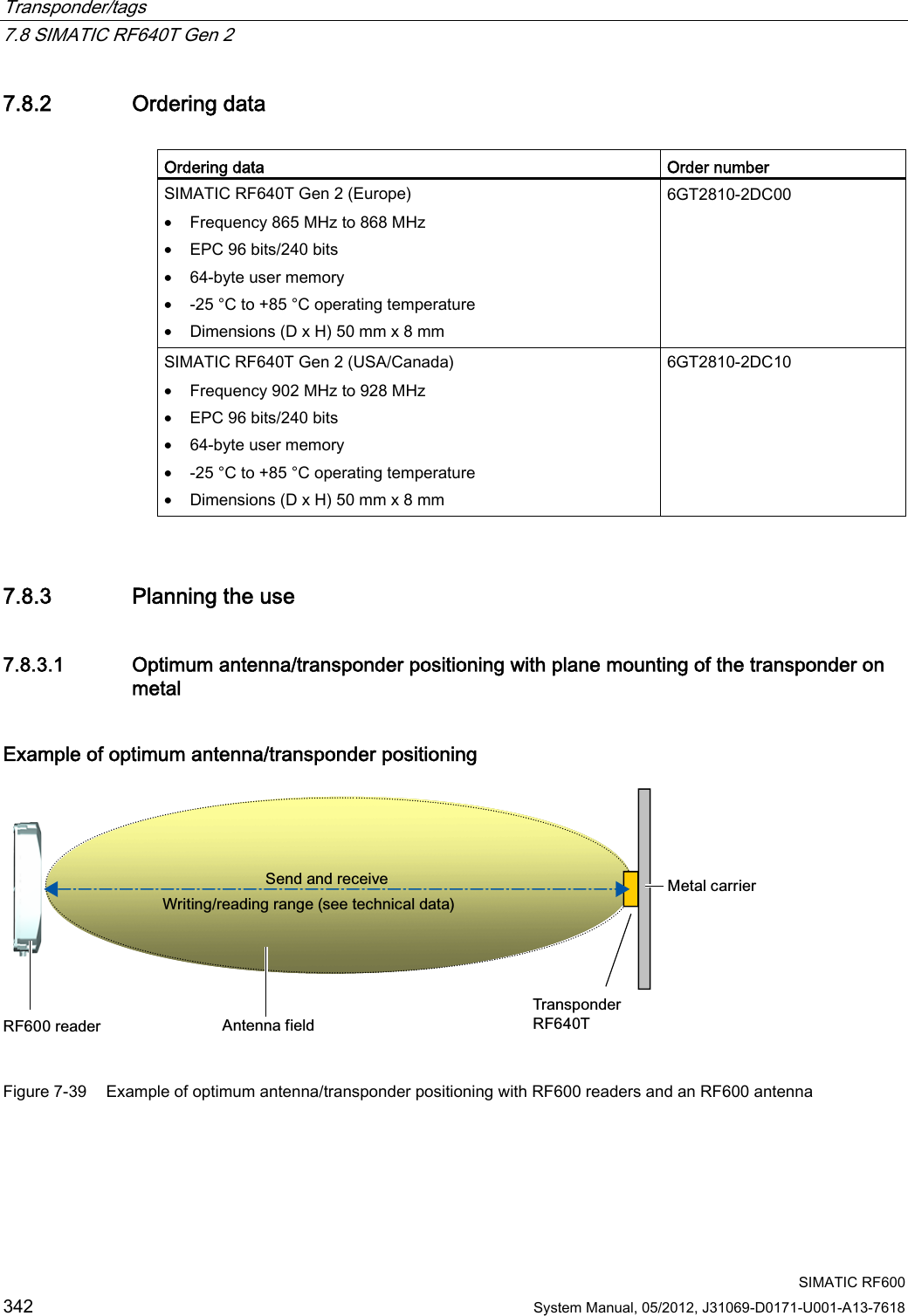
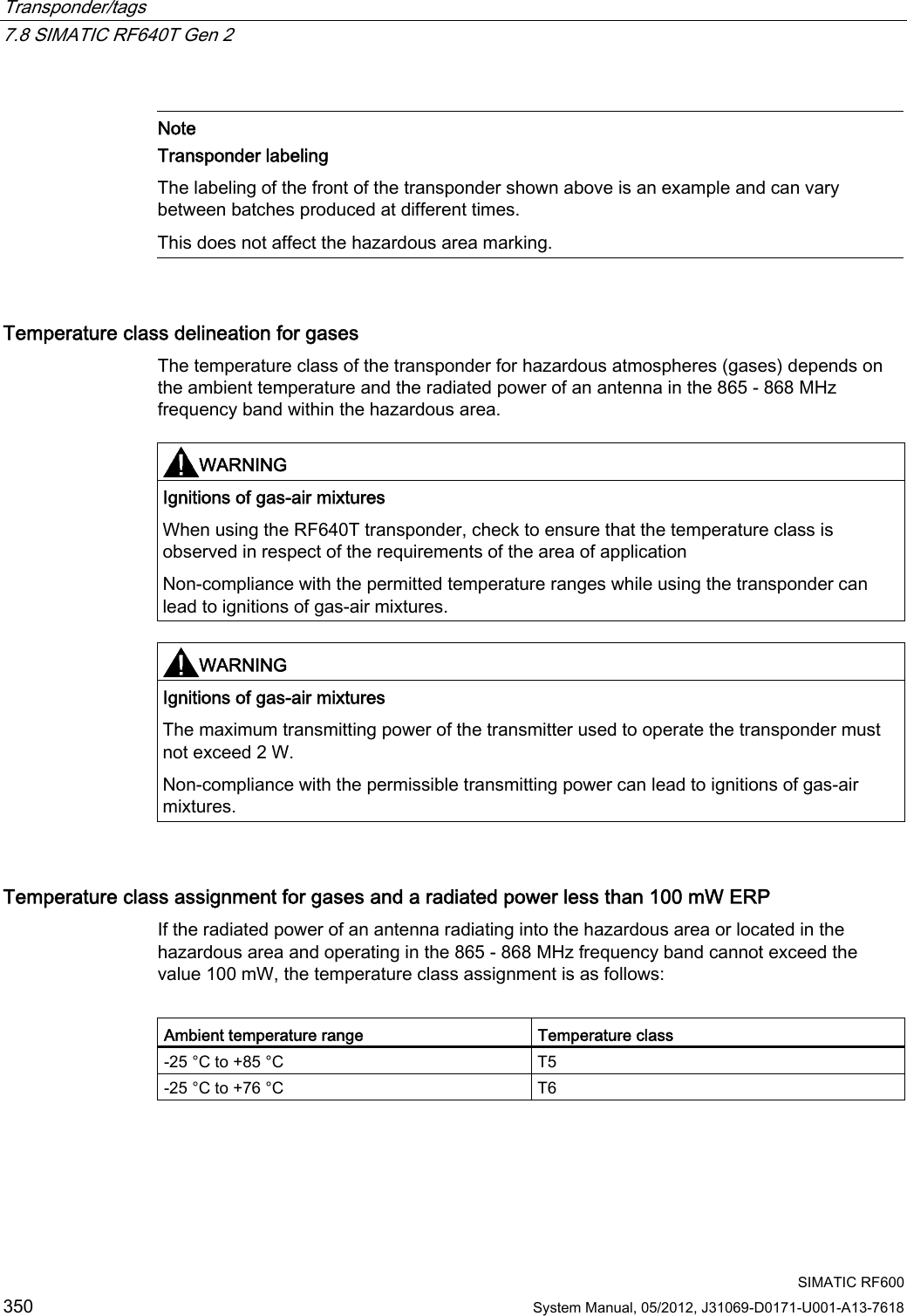
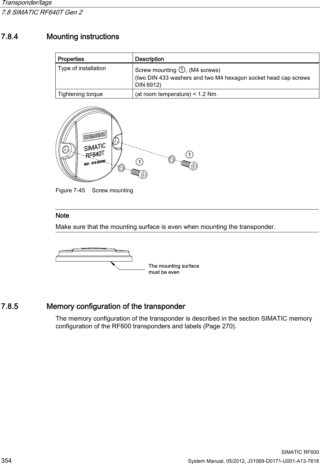
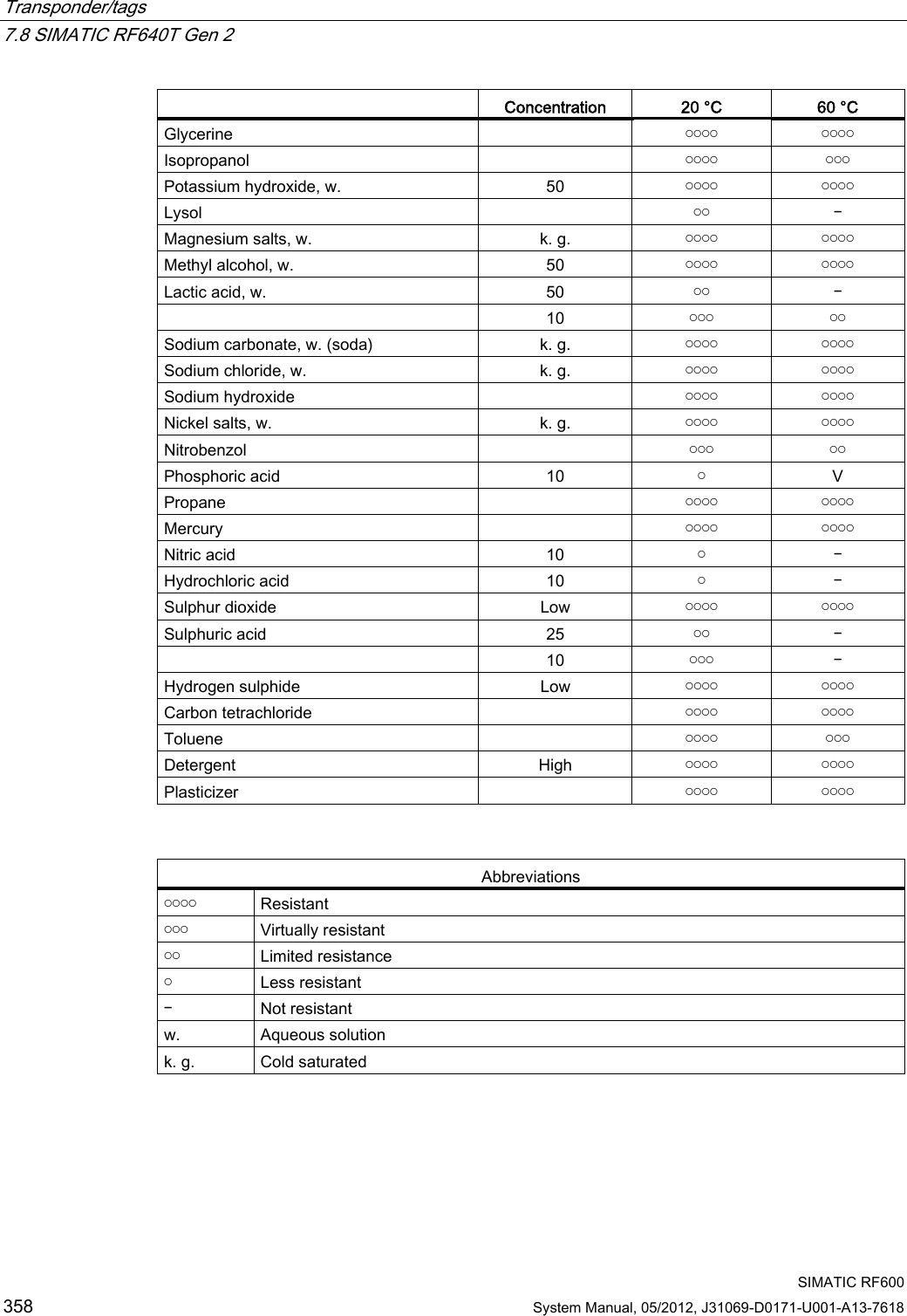
![Transponder/tags 7.8 SIMATIC RF640T Gen 2 SIMATIC RF600 System Manual, 05/2012, J31069-D0171-U001-A13-7618 343 7.8.3.2 Reading range when mounted on flat metallic carrier plates The transponder generally has linear polarization. The polarization axis runs as shown in the diagram below. If the tag is centrically mounted on a flat metal plate, which may either be almost square or circular, it can be aligned in any direction since the transmitting and receiving RF660A antennas operate with circular polarization. 3RODUL]DWLRQD[LV6TXDUHPHWDOFDUULHUSODWH&LUFXODUPHWDOFDUULHUSODWHr Figure 7-40 Optimum positioning of the transponder on a (square or circular) metal plate Table 7- 23 Reading range on flat metallic carrier plates Carrier plate material Reading range Metal plate of at least Ø 150 mm 100% Metal plate Ø 120 mm Approx. 80% Metal plate Ø 85 mm Approx. 55% Metal plate Ø 65 mm Approx. 40% On rectangular carrier plates, the reading distance depends on the mounting orientation of the transponder.](https://usermanual.wiki/Siemens/RF600R.User-manual-04/User-Guide-1716293-Page-35.png)
![Transponder/tags 7.8 SIMATIC RF640T Gen 2 SIMATIC RF600 344 System Manual, 05/2012, J31069-D0171-U001-A13-7618 7.8.3.3 Reading range when mounted on non-metallic carriers The transponder is generally designed for mounting on metallic objects which provide the conditions for the maximum reading ranges. Table 7- 24 Reading range on non-metallic carriers Carrier plate material Reading range Transponder on wooden carrier Approx. 40% Transponder on plastic carrier Approx. 35% Transponder on plastic mineral water bottle Approx. 55% Transponder without base Approx. 30% 100% reading distance refers to a metal plate of at least 150 mm diameter. 7.8.3.4 Influence of conducting walls on the reading range If there are conducting walls or restrictions in the vicinity that could affect the radio field, a distance of approx. 10 cm is recommended. In principle, walls have least influence if the polarization axis is orthogonal to the wall. Reading range: One conducting wall Influence on reading range when positioned against one conducting wall G&RQGXFWLQJZDOO3RODUL]DWLRQD[LV Top view Distance d 20 mm 50 mm 100 mm Approx. 90 % Approx. 90 % Approx. 95 % Wall height 20 mm Approx. 80 % Approx. 90 % Approx. 90 % Wall height 50 mm Reading range Approx. 70 % Approx. 75 % Approx. 90 % Wall height 100 mm](https://usermanual.wiki/Siemens/RF600R.User-manual-04/User-Guide-1716293-Page-36.png)
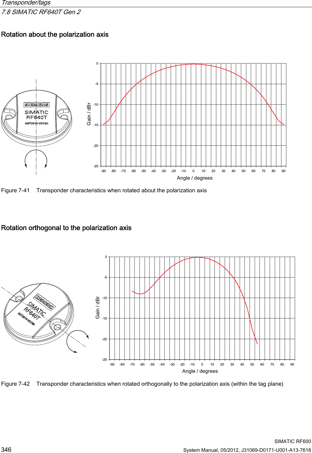
![Transponder/tags 7.8 SIMATIC RF640T Gen 2 SIMATIC RF600 System Manual, 05/2012, J31069-D0171-U001-A13-7618 345 Reading range: Two conducting walls Influence on reading range when positioned against two conducting walls GG&RQGXFWLQJZDOO&RQGXFWLQJZDOO3RODUL]DWLRQD[LV0HWDOFDUULHU Top view G0HWDOFDUULHU&RQGXFWLQJZDOO:DOOKHLJKW&RQGXFWLQJZDOO Side view Distance d 20 mm 50 mm 100 mm Approx. 75 % Approx. 90 % Approx. 90 % Wall height 20 mm Approx. 50 % Approx. 45 % Approx. 80 % Wall height 50 mm Reading range Approx. 40 % Approx. 45 % Approx. 75 % Wall height 100 mm The values specified in the tables above are guide values. 7.8.3.5 Directional radiation pattern of the transponder Preferably, align the tag parallel to the transmitting antenna. If, however, the tag including the metallic carrier plate is tilted, the reading range will be reduced.](https://usermanual.wiki/Siemens/RF600R.User-manual-04/User-Guide-1716293-Page-37.png)