Siemens RF600R RFID UHF Reader User Manual SIMATIC RF600
Siemens AG RFID UHF Reader SIMATIC RF600
Siemens >
Contents
- 1. User manual 01
- 2. User manual 02
- 3. User manual 03
- 4. User manual 04
- 5. User manual 05
User manual 04
Transponder/tags
7.5 SIMATIC RF620T
SIMATIC RF600
System Manual, 05/2012, J31069-D0171-U001-A13-7618 309
Characteristic Description
Energy source Magnetic energy via antenna, without battery
Multi-tag capability Yes, minimum distance between data carriers ≥ 50 mm
1) Metallic surface approx. 30 x 30 cm
2) For maximum read/write distances
See also
Reading range when mounted on ESD carrier materials (Page 304)
Reading range when mounted on flat metallic carrier plates (Page 301)
Reading range when mounted on non-metallic carriers (Page 297)
7.5.6.3 Memory specifications
Characteristic Description
Type EPC Class 1 Gen2
Memory organization EPC code 96/128 bit
User memory 64 byte
Protocol ISO 18000-6C
Data retention time 10 years
Read cycles Unlimited
Write cycles 100 000 min.
7.5.6.4 Environmental conditions
Property Description
Temperature range during operation -25 °C to +85 °C
Temperature range during storage -40 °C to +85 °C
Shock
Vibration
compliant with EN 60721-3-7 Class 7 M3
100 g,
50 g
Torsion and bending load Not permissible
Degree of protection IP67

Transponder/tags
7.5 SIMATIC RF620T
SIMATIC RF600
310 System Manual, 05/2012, J31069-D0171-U001-A13-7618
7.5.6.5 Chemical resistance of the transponder RF620T
The following table provides an overview of the chemical resistance of the data memory
made of polypropylene.
Concentration 20 °C 50 °C
Emissions
alkaline/containing hydrogen fluoride
/carbon dioxide
Low ○○○○ ○○○○
Emissions containing hydrochloric acid ○○○○ ○○○○
Emissions containing sulphuric acid ○○○○ -
Battery acid 38 ○○○○ ○○○○
Aluminum acetate, w. ○○○○ ○○○○
Aluminum chloride 10 ○○○○ ○○○○
Aluminum nitrate, w. ○○○○ ○○○○
Aluminum salts ○○○○ ○○○○
Formic acid 50 ○○○○ -
Aminoacetic acid (glycocoll, glycine) 10 ○○○○ ○○○○
Ammonia gas ○○○○ ○○○○
Ammonia 25 ○○○○ ○○○○
Ammonia, w. conc. ○○○○ ○○○○
10 ○○○○ ○○○○
Arsenic acid, w. ○○○○ ○○○○
Ascorbic acid, w. ○○○○ ○○○○
Petroleum spirit - -
Benzene ○○ -
Prussic acid, w. ○○○○ ○○○○
Sodium hypochlorite solution diluted /
20
○○○○ ○○
50 ○○ ○○
Borax ○○○○ ○○○○
Boric acid, w. 10 ○○○○ ○○○○
Brake fluid ○○○○ ○○○○
Bromine - -
Butane, gas, liquid techn. pure ○○○○ ○○○○
Butyl acetate (acetic acid butyl ester) ○○ -
Calcium chloride, w./ alcoholic ○○○○ ○○○
Calcium chloride, ○○○○ ○○○○
Calcium nitrate, w. ○○○○ ○○○○
50 ○○○○ ○○○○
Chlorine ᅳ ᅳ
Chloroacetic acid ○○○○ ○○○○
Chloric acid 20 ○○○○ -
Chrome baths, tech. ᅳ ᅳ

Transponder/tags
7.5 SIMATIC RF620T
SIMATIC RF600
System Manual, 05/2012, J31069-D0171-U001-A13-7618 311
Concentration 20 °C 50 °C
Chromium salts ○○○○ ○○○○
Chromic acid 10 ○○○○ ○○○○
20 / 50 ○○ ○○
Chromic acid, w ○○○○ ○○
Chromosulphuric acid conc. - -
Citric acid 10 ○○○○ ○○○○
Diesel fuel ○○○○
Diesel oil 100 ○○○○
Diglycole acid 30 ○○○○ ○○○○
Iron salts, w. k. g. ○○○○ ○○○○
Vinegar ○○○○ ○○○○
Acetic acid 5 / 50 ○○○○ ○○○○
Ethanol 50 / 96 ○○○○ ○○○○
Ethyl alcohol 96 / 40 ○○○○ ○○○○
Fluoride ○○○○ ○○○○
Formaldehyde 10 ○○○○ ○○○○
40 ○○○○ ○○○
Formaldehyde solution 30 ○○○○ ○○○○
Glycerin any ○○○○ ○○○○
Glycol ○○○○ ○○○○
Uric acid ○○○○
HD oil, motor oil, without aromatic
compounds
○○○○
Fuel oil ○○○○
Isopropanol techn. pure ○○○○ ○○○○
Potassium hydroxide, w. ○○○○ ○○○○
Potassium hydroxide 10 / 50 ○○○○ ○○○○
Silicic acid any ○○○○ ○○○○
Common salt ○○○○ ○○○○
Carbonic acid saturated ○○○○ ○○○○
Lysol ○○○○ ○○
Magnesium salts, w. k. g. ○○○○ ○○○○
Magnesium salts any ○○○○ ○○○○
Machine oil 100 ○○○○
Sea water ○○○○ ○○○○
Methanol ○○○○ ○○○○
Methyl alcohol, w. 50 ○○○○ ○○○○
Lactic acid, w. ○○○○ ○○○○
Lactic acid 3 / 85 ○○○○ ○○○
80 ○○○○ ○○○○
Engine oil ○○○○
Sodium carbonate, w. (soda) k. g. ○○○○ ○○○○

Transponder/tags
7.5 SIMATIC RF620T
SIMATIC RF600
312 System Manual, 05/2012, J31069-D0171-U001-A13-7618
Concentration 20 °C 50 °C
Sodium carbonate ○○○○ ○○○○
Sodium chloride, w. k. g. ○○○○ ○○○○
Sodium hydroxide, w. ○○○○ ○○○○
Sodium hydroxide solution, w. ○○○○ ○○○○
Sodium hydroxide solution 30 / 45 / 60 ○○○○ ○○○○
Nickel salts, w. k. g. ○○○○ ○○○○
Nickel salts saturated ○○○○ ○○○○
Nitrobenzol ○○○ ○○
Oxalic acid ○○○○ ○○○○
Petroleum techn. pure ○○○○
Phosphoric acid 1-5 / 30 ○○○○ ○○○○
85 ○○○○ ○○○
Phosphoric acid, w 20 ○○○○ ○○○○
Propane liquid ○○○○
Propane gaseous ○○
Mercury pure ○○○○ ○○○○
Crude oil 100 ○○○○ ○○
Ammonium chloride 100 ○○○○ ○○○○
Ammonium chloride, w. ○○○○ ○○○○
Nitric acid - -
50 ○○
1-10 ○○○○ ○○○○
Hydrochloric acid 1-5 / 20 ○○○○ ○○○○
35 ○○○○ ○○○
conc. ○○○○ ○○○○
Sulphur dioxide Low ○○○○ ○○○○
moist ○○○○ ○○
liquid - -
Sulphuric acid 1-6 / 40 / 80 ○○○○ ○○○○
20 ○○○○ ○○○
60 ○○○○ ○○
95 ○○ -
fuming - -
Hydrogen sulphide Low/saturated ○○○○ ○○○○
Detergent High ○○○○ ○○○○
Water ○○○○ ○○○○
Hydrogen techn. pure ○○○○ ○○○○
Plasticizer ○○○○ ○○
Transponder/tags
7.5 SIMATIC RF620T
SIMATIC RF600
System Manual, 05/2012, J31069-D0171-U001-A13-7618 313
Abbreviations
○○○○ Resistant
○○○ Virtually resistant
○○ Limited resistance
○ Less resistant
ᅳ Not resistant
w. Aqueous solution
k. g. Cold saturated
7.5.7 Certificates and approvals
Table 7- 14 6GT2810-2HC00 - RF620T UHF container tag
Certificate Description
CE Approval to R&TTE
Table 7- 15 6GT2810-2HC80 - RF620T UHF container tag
Standard
FCC
Federal Communications
Commission
Passive labels or transponders comply with the valid regulations;
certification is not required.
This product is UL-certified for the USA and Canada.
It meets the following safety standard(s):
• UL508 - Industrial Control Equipment
• CSA C22.2 No. 142 - Process Control Equipment
• UL Report E 120869
Transponder/tags
7.5 SIMATIC RF620T
SIMATIC RF600
314 System Manual, 05/2012, J31069-D0171-U001-A13-7618
7.5.8 Dimension drawing
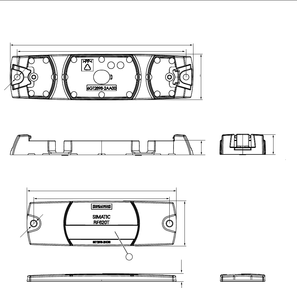
Figure 7-24 SIMATIC RF620T UHF container tag
Units of measurement: All dimensions in mm
Tolerances, unless indicated otherwise, are +-0.5 mm.
① Labeling area, see Section Characteristics (Page 296)
Transponder/tags
7.6 SIMATIC RF625T
SIMATIC RF600
System Manual, 05/2012, J31069-D0171-U001-A13-7618 315
7.6 SIMATIC RF625T
7.6.1 Characteristics
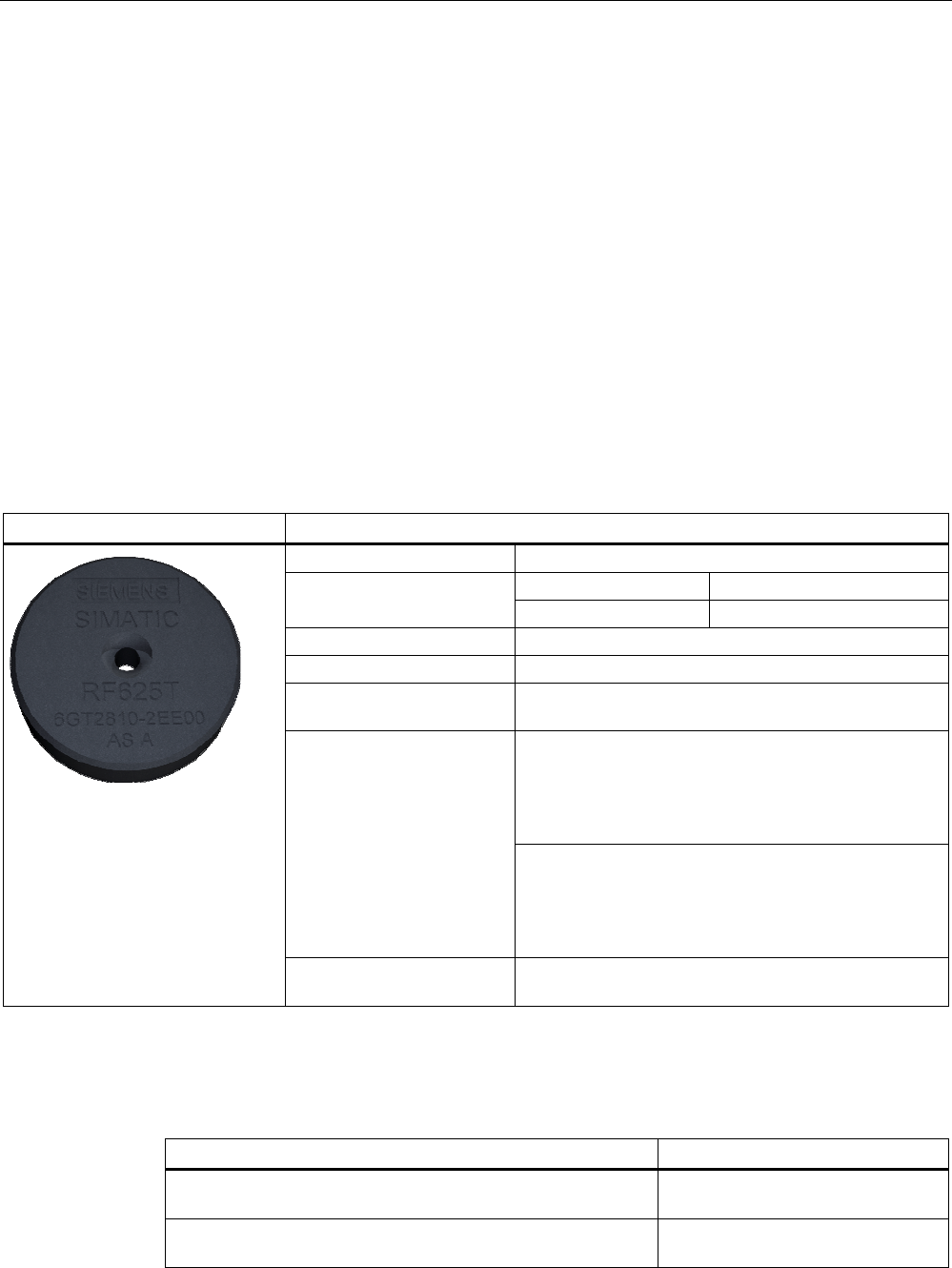
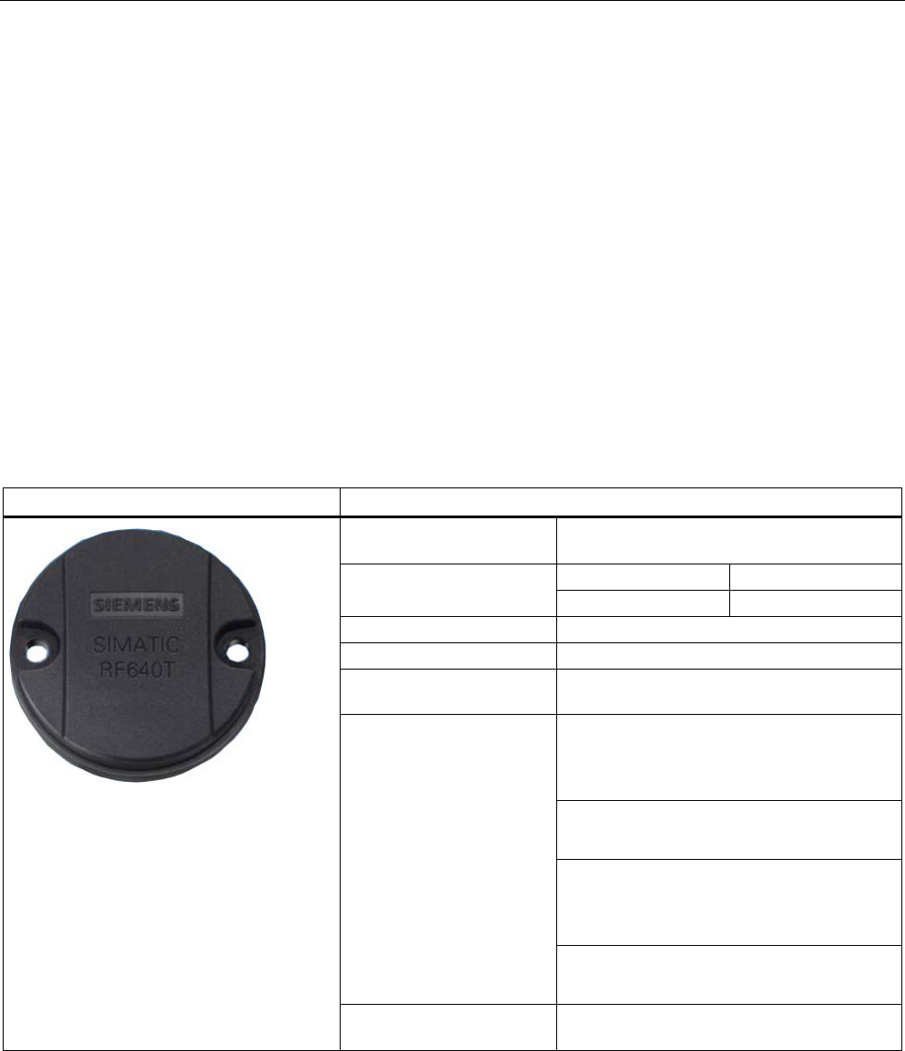
The SIMATIC RF625T transponder is a passive, maintenance-free data carrier with a round
design. It operates based on the UHF Class 1 Gen 2 technology and is used to save the
"Electronic Product Code" (EPC) of 96 bits/128 bits. The transponder also has a 512-bit user
memory.
Fields of application are industrial asset management, RF identification of tools, containers
and metallic equipment.
The Disk Tag is small and rugged and suitable for industrial applications with degree of
protection IP68. It is highly resistant to oil, grease and cleaning agents.
Ideally, the SIMATIC RF625T is mounted directly on a flat metal surface of at least 150 mm
diameter where it achieves a typical sensing distance of 1.5 m.
SIMATIC RF625T Features
Application Identification tasks in rugged industrial environments
Europe USA / Canada Frequency versions
865 MHz ... 868 MHz 902 MHz ... 928 MHz
Air interface according to ISO°18000-6C
Polarization Linear
Memory EPC 96 bits/128 bits
Add-on-memory 64 bytes
typically 1.5 m in conjunction with:
• RF640R/RF670R reader and
RF660A antenna
• RF640R reader with integrated antenna
Reading / writing range
typically 0.7 m in conjunction with:
• RF620R/RF630R reader and
RF660A antenna
• RF620R reader with integrated antenna
Installation Suitable for direct mounting on conductive materials
(preferably metal)
7.6.2 Ordering data
Ordering data Order no.
SIMATIC RF625T (Europe),
frequency range 865 MHz ... 868 MHz
6GT2810-2EE00
SIMATIC RF625T (USA / Canada),
frequency range 902 MHz ... 928 MHz
6GT2810-2EE01
Transponder/tags
7.6 SIMATIC RF625T
SIMATIC RF600
316 System Manual, 05/2012, J31069-D0171-U001-A13-7618
7.6.3 Planning the use
7.6.3.1 Optimum antenna/transponder positioning with planar mounting of the transponder on
metal
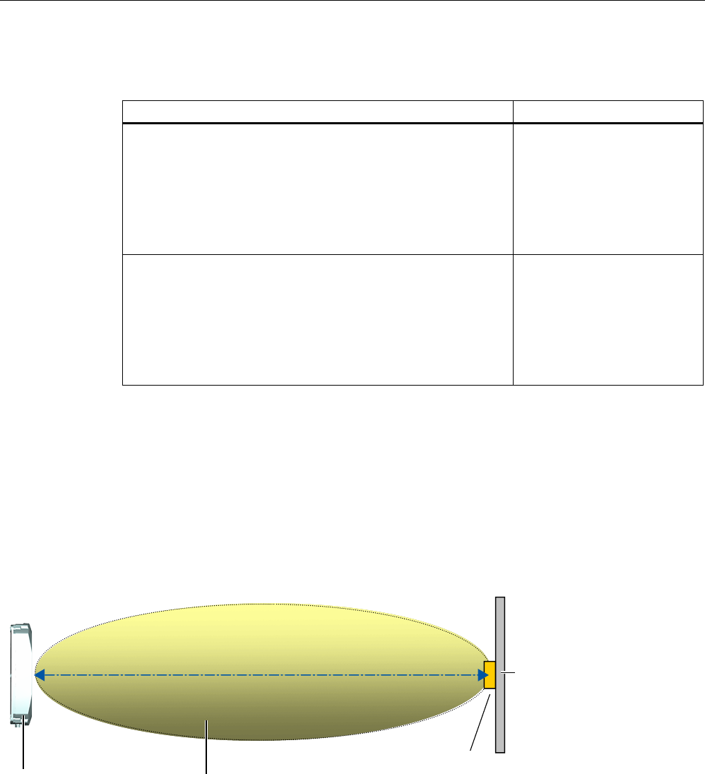
Example of optimum reader-transponder positioning with RF620R and RF640R
7UDQVSRQGHU
5)7
0HWDOFDUULHU
5)5
5)5
$QWHQQDILHOG
:ULWLQJUHDGLQJUDQJHVHHWHFKQLFDOGDWD
6HQGDQGUHFHLYH
Figure 7-25 Example of optimum reader-transponder positioning with RF620R and RF640R via the internal reader
antenna.
Example of optimum antenna-transponder positioning with RF620R, RF630R, RF640R and RF670R
7UDQVSRQGHU
5)7
0HWDOFDUULHU
5)$
5)$
5)$
5)$
$QWHQQDILHOG
:ULWLQJUHDGLQJUDQJHVHHWHFKQLFDOGDWD
6HQGDQGUHFHLYH
Figure 7-26 Example of optimum antenna-transponder positioning with the RF620R, RF630R, RF640R and RF670R
readers in conjunction with the external antennas RF620A, RF640A, RF642A or RF660A.
Transponder/tags
7.6 SIMATIC RF625T
SIMATIC RF600
System Manual, 05/2012, J31069-D0171-U001-A13-7618 317
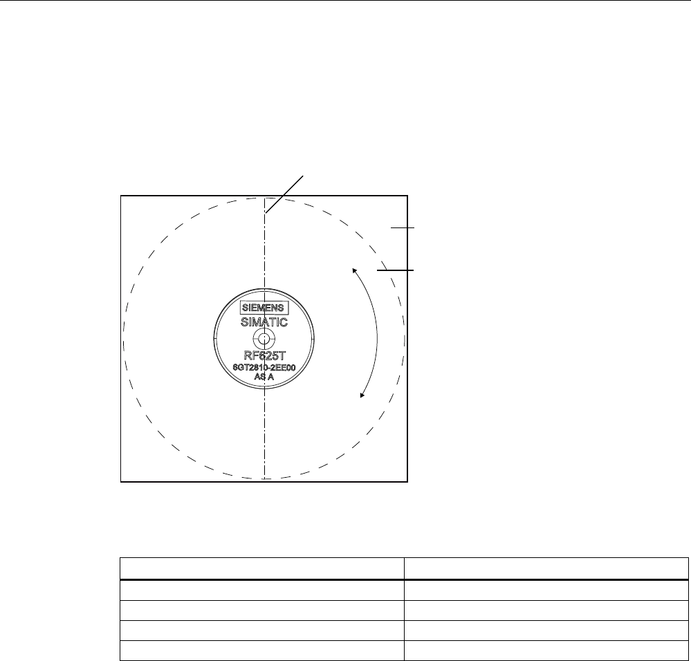
7.6.3.2 Reading range when mounted on flat metallic carrier plates
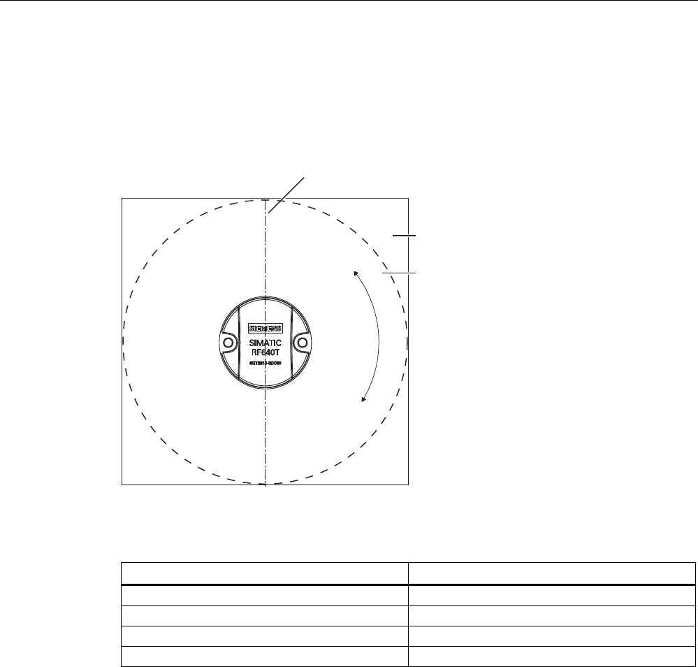
The transponder generally has linear polarization. The polarization axis runs as shown in the
diagram below. If the tag is centrically mounted on a flat metal plate, which may either be
almost square or circular, it can be aligned in any direction since the transmitting and
receiving RF660A antennas operate with circular polarization.
3RODUL]DWLRQD[LV
6TXDUH
0HWDOFDUULHU
&LUFXODUPHWDO
FDUULHUSODWH
r
Figure 7-27 Optimum positioning of the transponder on a (square or circular) metal plate
Table 7- 16 Reading range on flat metallic carrier plates
Carrier plate material Reading range
Metal plate of at least Ø 150 mm 100 %
Metal plate Ø 120 mm Approx. 70 %
Metal plate Ø 85 mm Approx. 60 %
Metal plate Ø 65 mm Approx. 60 %
On rectangular carrier plates, the reading range depends on the mounting orientation of the
transponder You will find more detailed information on reading ranges in the section
"Electrical data (Page 324)".
Transponder/tags
7.6 SIMATIC RF625T
SIMATIC RF600
318 System Manual, 05/2012, J31069-D0171-U001-A13-7618
7.6.3.3 Reading range when mounted on non-metallic carrier materials
The transponder is generally designed for mounting on metallic objects which provide the
conditions for the maximum reading ranges
Table 7- 17 Reading range on non-metallic carriers
Carrier plate material Reading range 1)
Transponder on wooden carrier Approx. 60 %
Transponder on plastic carrier Approx. 65 %
Transponder on plastic mineral water bottle Approx. 70 %
Transponder without base Approx. 50 %
1) The maximum read range of 100 % is achieved by mounting the transponder on a flat metallic
carrier with a diameter of at least 150 mm.
You will find more detailed information on reading ranges in the section "Electrical data
(Page 324)".
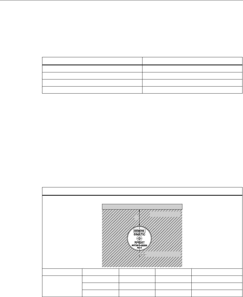
7.6.3.4 Influence of conducting walls on the reading range
If there are conducting walls or restrictions in the vicinity that could affect the radio field, a
distance of approx. 10 cm is recommended. In principle, walls have least influence if the
polarization axis is orthogonal to the wall.
Reading range: One conducting wall
Influence on reading range when positioned against one conducting wall
View from above
&RQGXFWLQJZDOO
3RODUL]DWLRQD[LV
0HWDOFDUULHU
G
Distance d 20 mm 50 mm 100 mm
Approx. 100 % Approx. 100 % Approx. 100 % Wall height 20 mm
Approx. 100 % Approx. 100 % Approx. 100 % Wall height 50 mm
Reading range
Approx. 80 % Approx. 100 % Approx. 100 % Wall height 100 mm
Transponder/tags
7.6 SIMATIC RF625T
SIMATIC RF600
System Manual, 05/2012, J31069-D0171-U001-A13-7618 319
Reading range: Two conducting walls
Influence on reading range when positioned against two conducting walls
View from above
&RQGXFWLQJZDOO
&RQGXFWLQJZDOO
3RODUL]DWLRQD[LV
0HWDOFDUULHU
G
G
Side view
0HWDOFDUULHU
&RQGXFWLQJZDOO
:DOOKHLJKW
&RQGXFWLQJ
ZDOO
G
Distance d 20 mm 50 mm 100 mm
Approx. 70 % Approx. 75 % Approx. 100 % Wall height 20 mm
Approx. 70 % Approx. 80 % Approx. 100 % Wall height 50 mm
Reading range
Approx. 70 % Approx. 40 % Approx. 50 % Wall height 100 mm
The values specified in the tables above are guide values.
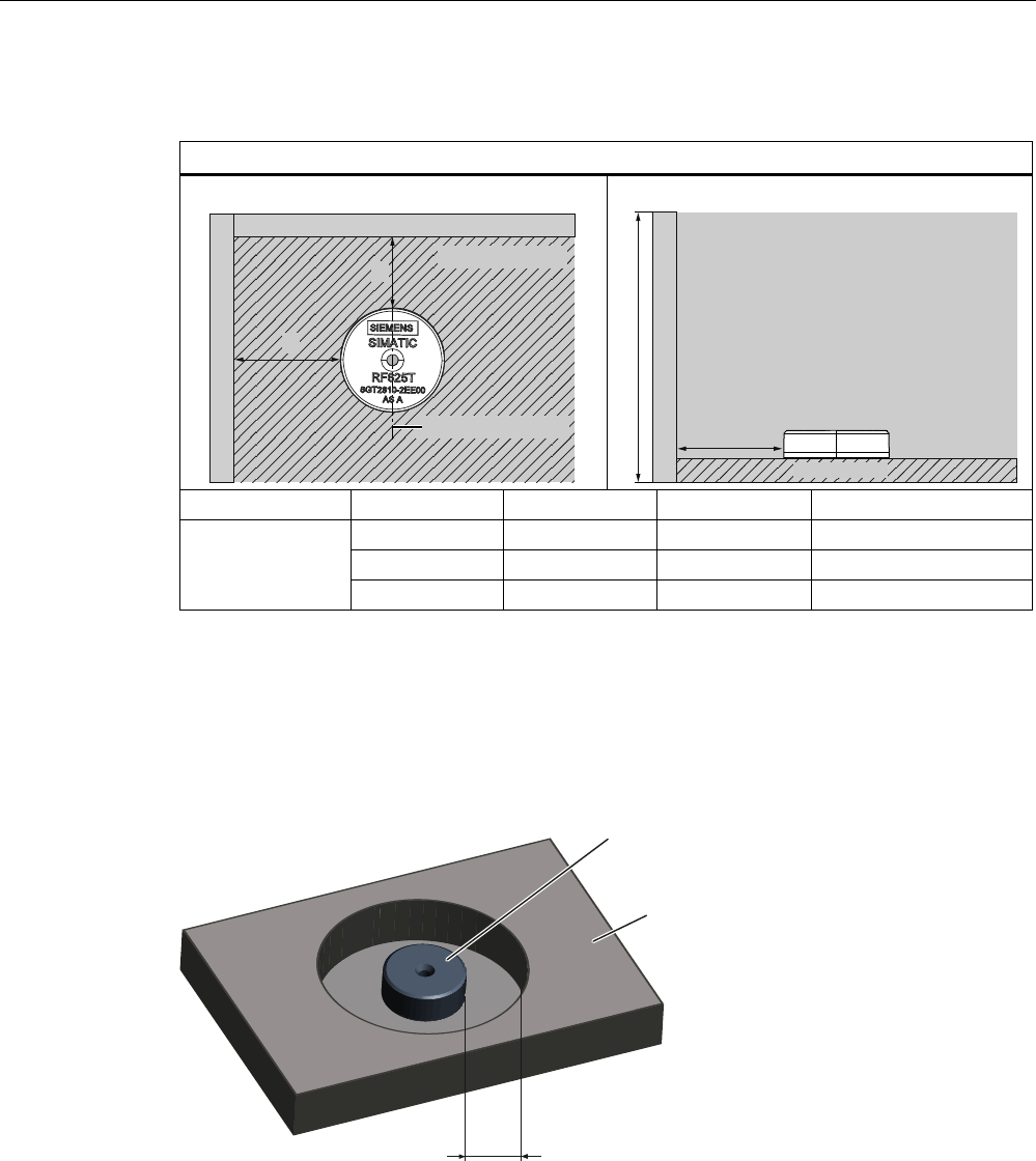
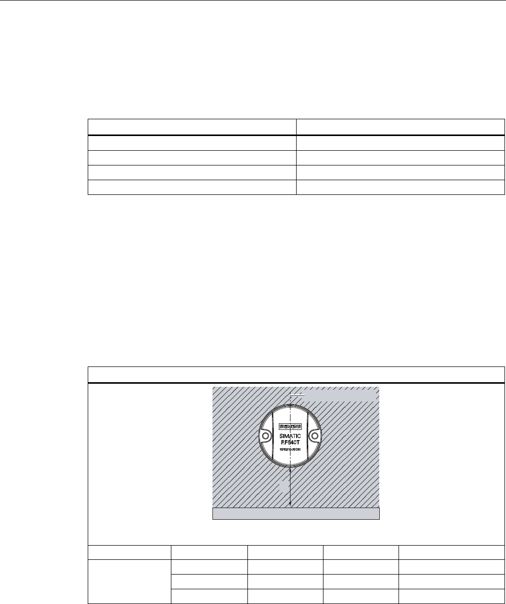
7.6.3.5 Mounting in metal
It is possible to mount the transponder in metal. If there is not enough clearance to the
surrounding metal, this reduces the reading range.
7UDQVSRQGHU
0HWDO
D
Clearance (all-round) Reading range 1)
a = 5 mm Approx. 50 %
a = 10 mm Approx. 70%
1) The read range information applies when the transponder is mounted on a metallic carrier with a
diameter of at least 150 mm.
Figure 7-28 Flush-mounting of RF625T in metal
Transponder/tags
7.6 SIMATIC RF625T
SIMATIC RF600
320 System Manual, 05/2012, J31069-D0171-U001-A13-7618
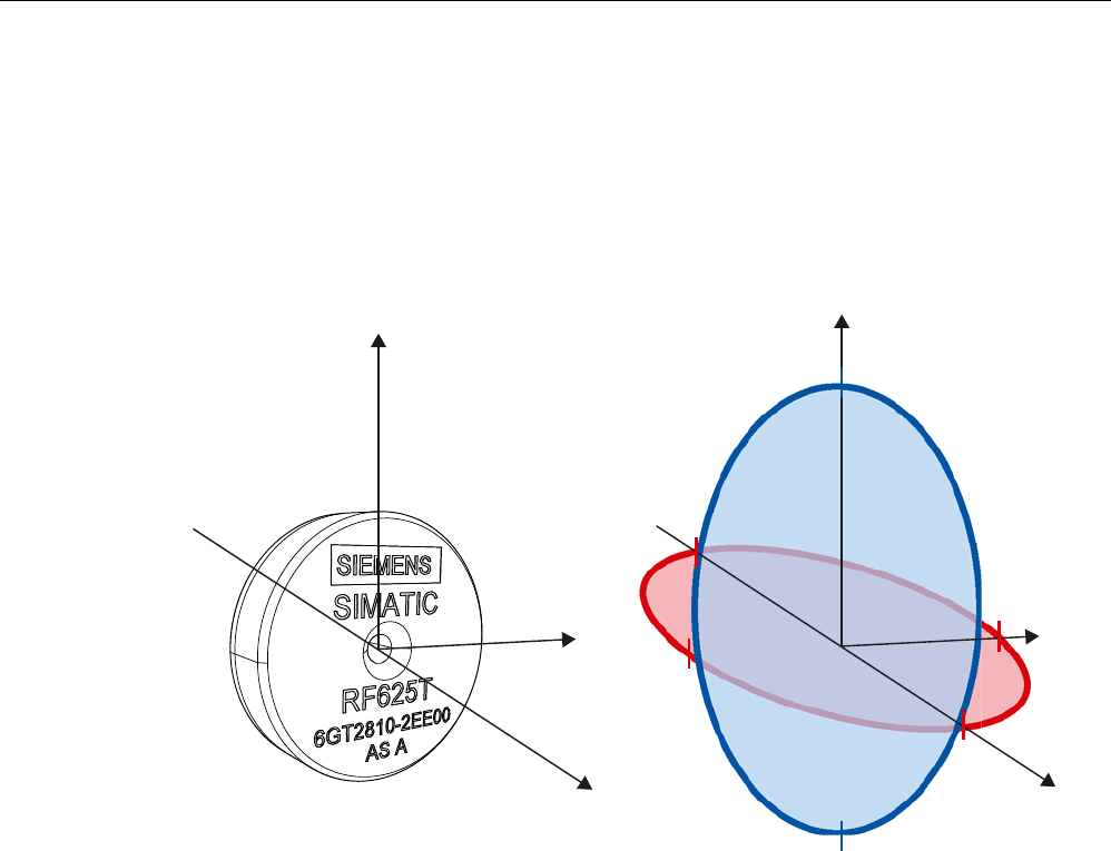
7.6.3.6 Directional radiation pattern of the transponder
Directional diagram in the ETSI frequency band (Europe)
The directional diagram is shown for nominal alignment and a center frequency of 866.3
MHz. The nominal transponder alignment is achieved when the transponder is viewed as
shown in the following figure.
;
<
=
;
<
=
r
r
r
r
r
r
Figure 7-29 Reference system of the RF625T
Ideally, align the data carrier parallel with the transmitting antenna or the reader. If the data
carrier including the (metallic) carrier plate is tilted, the reading range will be reduced. The
following diagrams show the effects on the reading range depending on the carrier material
and the angle of inclination of the transponder.
Transponder/tags
7.6 SIMATIC RF625T
SIMATIC RF600
System Manual, 05/2012, J31069-D0171-U001-A13-7618 321
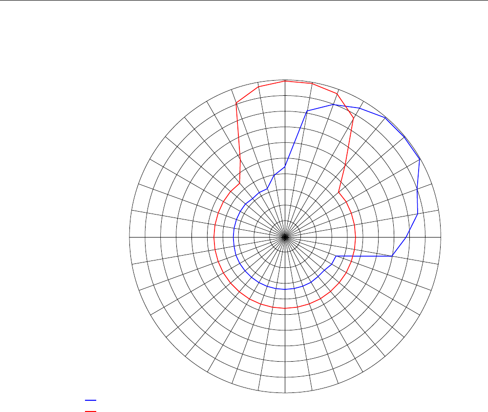
Directional characteristics of the transponder when mounted on a metallic carrier
9HUWLFDO
+RUL]RQWDO $QJOHGHJUHHV
5HDGLQJUDQJHSHUFHQWDJH
Figure 7-30 Directional characteristics of the RF625T on a metallic carrier depending on the angle of
inclination in a vertical or horizontal direction
Transponder/tags
7.6 SIMATIC RF625T
SIMATIC RF600
322 System Manual, 05/2012, J31069-D0171-U001-A13-7618
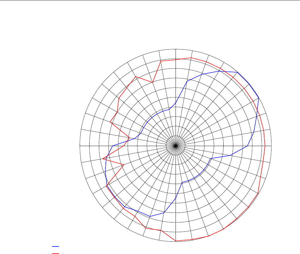
Directional characteristics of the transponder when mounted on a non-metallic carrier
$QJOHGHJUHHV
9HUWLFDO
+RUL]RQWDO
5HDGLQJUDQJHSHUFHQWDJH
Figure 7-31 Directional characteristics of the RF625T on a non-metallic carrier depending on the
angle of inclination in a vertical or horizontal direction
Transponder/tags
7.6 SIMATIC RF625T
SIMATIC RF600
System Manual, 05/2012, J31069-D0171-U001-A13-7618 323
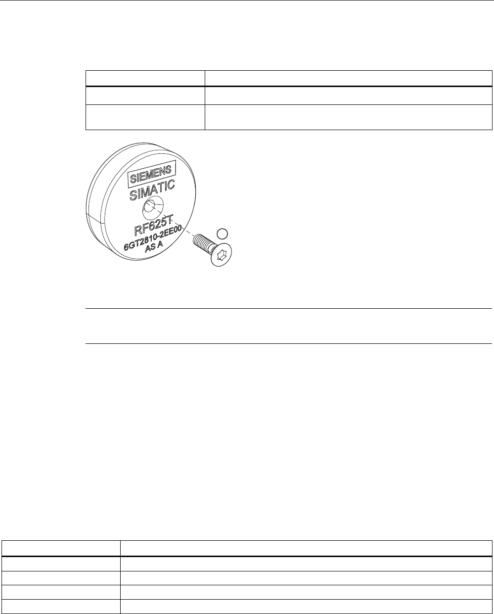
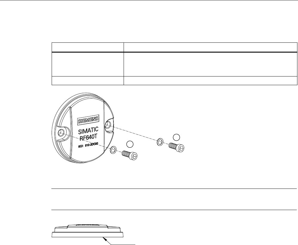
7.6.4 Mounting instructions
Properties Description
Type of installation Secured with screw ①, (M3 counter-sunk head screw)
Tightening torque
(at room temperature)
≤ 1.0 Nm
Figure 7-32 Screw mounting
Note
Make sure that the mounting surface is even when mounting the transponder.
7.6.5 Memory configuration of the transponder
The memory configuration of the transponder is described in the section SIMATIC memory
configuration of the RF600 transponders and labels (Page 270).
7.6.6 Technical Specifications
7.6.6.1 Mechanical data
Property Description
Dimensions (D x H) 30 (+0.5) mm x 8 (+0.5) mm
Design Plastic housing (PA6.6), silicone-free
Weight Approx. 6 g
Mounting on metal directly on metal without spacing

Transponder/tags
7.6 SIMATIC RF625T
SIMATIC RF600
324 System Manual, 05/2012, J31069-D0171-U001-A13-7618
7.6.6.2 Electrical data
Description Property
Europe USA / Canada
Air interface According to ISO 18 000-6 C According to ISO 18 000-6 C
Frequency range 865 MHz … 868 MHz 902 MHz ... 928 MHz 1)
Necessary transmit power 2 W (ERP) 4 W (EIRP)
Reading range 2)
Mounting on non-metal
Mounting on metal 3)
typical 1.0 m
min. 1.2 m; typical 1.5 m
typical 1.0 m
min. 1.2 m; typical 1.5 m
Writing range 2)
Mounting on non-metal
Mounting on metal 3)
typical 0.7 m
min. 1 m; typical 1.2 m
typical 0.7 m
min. 1 m; typical 1.2 m
Polarization type Linear Linear
Minimum distance to transmit
antenna 4)
Approx. 0.2 m Approx. 0.2 m
Energy source Magnetic energy via antenna, without
battery
Magnetic energy via antenna, without
battery
Multi-tag capability Yes, minimum distance between data
carriers ≥ 50 mm 5)
Yes, minimum distance between data
carriers ≥ 50 mm 5)
1) Reduction of range to about 70% at the band limits 902 MHz or 928 MHz; acquisition is guaranteed at 915 MHz due to
frequency hopping procedure.
2) Tolerances of ±20% of the maximum acquisition ranges are permitted due to production and temperature conditions.
3) Mounting on a flat surface with a diameter of at least 150 mm
4) When using the RF620R and RF640R readers in conjunction with the antennas RF640A, RF642A and RF660A.
5) When these minimum clearances are not kept to, there is a reduction in the maximum possible read and write ranges of
the transponders.
You will find more detailed information on reading range, directional characteristics and
installation in the sections "Planning the use (Page 316)" and "Mounting instructions
(Page 323)".
7.6.6.3 Information on memory
Property Description
Type EPC Class 1 Gen 2
EPC code 96 bits/128 bits
User memory 64 bytes
TID 96 bits
Memory organization
Reserved (passwords) 64 bits
Protocol ISO 18000-6C
Data retention time 10 years
Read cycles Unlimited
Write cycles Minimum 100 000, at +22 °C

Transponder/tags
7.6 SIMATIC RF625T
SIMATIC RF600
System Manual, 05/2012, J31069-D0171-U001-A13-7618 325
7.6.6.4 Environmental conditions
Property Description
Temperature range during operation -25 °C … +85 °C
Temperature range during storage -40 °C … +125 °C
Shock resistant to EN 60068-2-27
Vibration to EN 60068-2-6
50 g, 1)
20 g, 1)
Torsion and bending load Not permissible
IP68 according to EN 60529:
(45 minutes. immersion in water; water depth
1 m from
top edge of housing at +20 °C)
Degree of protection
IPx9K to EN 60529:
• Steam blaster nozzle distance 150 mm
• 10 ... 15 l water per minute
• Pressure 100 bar
• Temperature 75 °C
• Test time 30 seconds
MTBF 2 x 10 5 hours
1) The values for shock and vibration are maximum values and must not be applied
continuously.
7.6.6.5 Chemical resistance of the RF625T transponder
The following table provides an overview of the chemical resistance of the data memory
made of polyamide 6.6. It must be emphasized that the plastic housing is extremely resistant
to chemicals in automobiles (e.g.: oil, grease, diesel fuel, gasoline) which are not listed
separately.
Substance Concentration
Mineral lubricants ■
Aliphatic hydrocarbons ■
Aromatic hydrocarbons ■
Petroleum spirit ■
Weak mineral acids ◪
Strong mineral acids □
Weak organic acids ◪
Strong organic acids □
Oxidizing acids □
Weak alkalis ◪
Strong alkalis □
Trichloroethylene ■
Perchloroethylene ■
Acetone ■
Transponder/tags
7.6 SIMATIC RF625T
SIMATIC RF600
326 System Manual, 05/2012, J31069-D0171-U001-A13-7618
Substance Concentration
Alcohols ■
Hot water (hydrolysis resistance) ◪
Abbreviations:
■ Resistant
◪ Limited resistance
□ Not resistant
7.6.7 Certificates and approvals
Table 7- 18 SIMATIC RF625T UHF Disk Tag (Europe), 6GT2810-2EE00
Certificate Description
Conforms to R&TTE directive
Table 7- 19 SIMATIC RF625T UHF Disk Tag (USA/Canada), 6GT2810-2EE01
Standard
FCC
Federal
Communications
Commission
Passive labels or transponders comply with the valid regulations;
certification is not required
This product is UL-certified for the USA and Canada.
It meets the following safety standard(s):
• UL508 - Industrial Control Equipment
• CSA C22.2 No. 142 - Process Control Equipment
• UL Report E 120869
Transponder/tags
7.6 SIMATIC RF625T
SIMATIC RF600
System Manual, 05/2012, J31069-D0171-U001-A13-7618 327
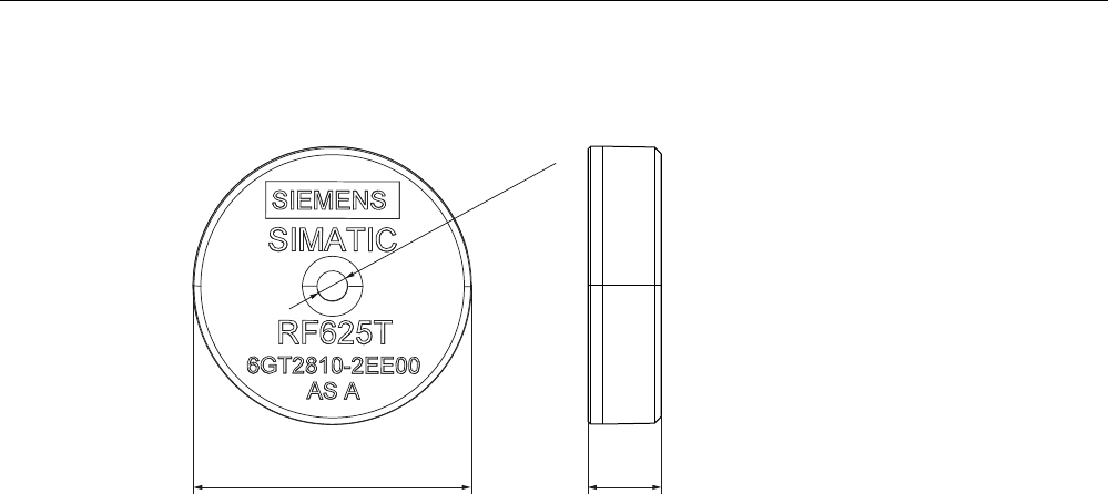
7.6.8 Dimension drawing
ෘs
Figure 7-33 SIMATIC RF625T UHF Disk Tag
Units of measurement: All dimensions in mm
Transponder/tags
7.7 SIMATIC RF630T
SIMATIC RF600
328 System Manual, 05/2012, J31069-D0171-U001-A13-7618
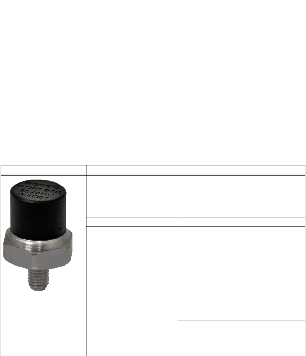
7.7 SIMATIC RF630T
7.7.1 Characteristics
The SIMATIC RF630T transponder is a passive (i.e. battery-free) and maintenance-free,
cylindrical data carrier. It operates based on the UHF Class 1 Gen 2 technology and is used
to save the "Electronic Product Code" (EPC) of 96 bits/240 bits. The transponder also has a
512-bit user memory.
Application areas include the mounting of metallic components (e.g. engine assembly in the
automobile industry) as well as RF identification of tools, containers and metal frames.
The RF630T is small and rugged and suitable for industrial applications with IP68/IPX9K
degree of protection. It is highly resistant to oil, grease and cleaning agents.
The SIMATIC RF630T is mounted directly onto metal surfaces to ensure optimum
functioning and its typical detection range is 1.5 m.
SIMATIC RF630T transponder Features
Application Identification tasks in rugged industrial
environments
Europe USA / Canada Frequency versions
868 MHz 915 MHz
Air interface according to ISO°18000-6C
Polarization Linear
Memory EPC 96 bit/240 bit
Add-on-memory 64 bytes
typically 1.2 m in conjunction with:
• RF640R/RF670R reader and
• RF660A antennas
typically 1.1 m in conjunction with:
• RF640R with integrated antenna
Typically 0.8 m in connection with:
• RF620R/RF630R reader and
• RF660A antenna
Reading / writing range
typically 0.7 m in conjunction with:
• RF620R with integrated antenna
Installation Suitable for direct mounting on conductive
materials (preferably metal)

Transponder/tags
7.7 SIMATIC RF630T
SIMATIC RF600
System Manual, 05/2012, J31069-D0171-U001-A13-7618 329
7.7.2 Ordering data
Ordering data Order no.
SIMATIC RF630T (Europe)
• For attaching to metal surfaces
• Frequency 865 MHz to 868 MHz
6GT2810-2EC00
SIMATIC RF630T (USA / Canada)
• For attaching to metal surfaces
• Frequency 902 MHz to 928 MHz
6GT2810-2EC10
7.7.3 Planning application
7.7.3.1 Optimum antenna/transponder positioning with plane mounting of the transponder on
metal
The maximum reading range is achieved when the reader antenna is positioned at right
angles to the mounting surface. In the case of parallel mounting directly above the
transponder, detection is not possible.
Positioning of the RF660A antenna in combination with the RF670R/RF630R reader
The RF670R and RF630R reader can operate with an RF660A antenna which can be
positioned as shown.
Transponder/tags
7.7 SIMATIC RF630T
SIMATIC RF600
330 System Manual, 05/2012, J31069-D0171-U001-A13-7618
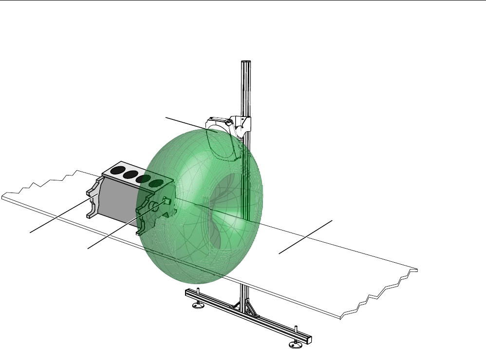
RF630T application example
&RQYH\RUEHOW
$QWHQQD
5)$
(QJLQHEORFN
RUREMHFW
PDGHRIPHWDO 5)7
WUDQVSRQGHU
Figure 7-34 RF630T application example
Transponder/tags
7.7 SIMATIC RF630T
SIMATIC RF600
System Manual, 05/2012, J31069-D0171-U001-A13-7618 331
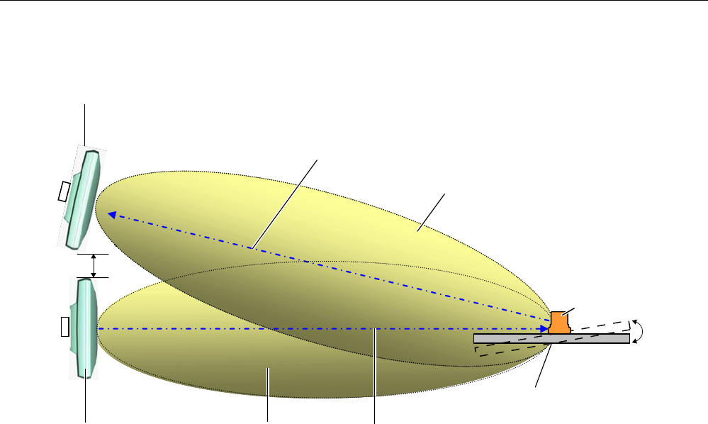
Positioning of two RF660A antennas
5)7
WUDQVSRQGHU
0HWDOFDUULHU
5HFHLYHILHOG
5HFHLYH
7[DQWHQQD
5[DQWHQQD
7UDQVPLWILHOG
'LVWDQFHFP
5HDGLQJGLVWDQFHVHHWHFKQLFDOVSHFLILFDWLRQV
7UDQVPLW
r
Figure 7-35 Example of optimum antenna/transponder positioning
Depending on the design of the metal bracket (surface parallel to the transmitting antenna),
an angle of 10° will have a favorable effect.
Positioning of the RF620R reader
The RF620R reader with an integrated circular polarized antenna can be placed in the same
position as the RF660A antennas with reference to the RF630T transponder.
Please note the different reading ranges for the RF600 readers in SectionAuto-Hotspot
.
See also
Electrical data (Page 336)
Transponder/tags
7.7 SIMATIC RF630T
SIMATIC RF600
332 System Manual, 05/2012, J31069-D0171-U001-A13-7618
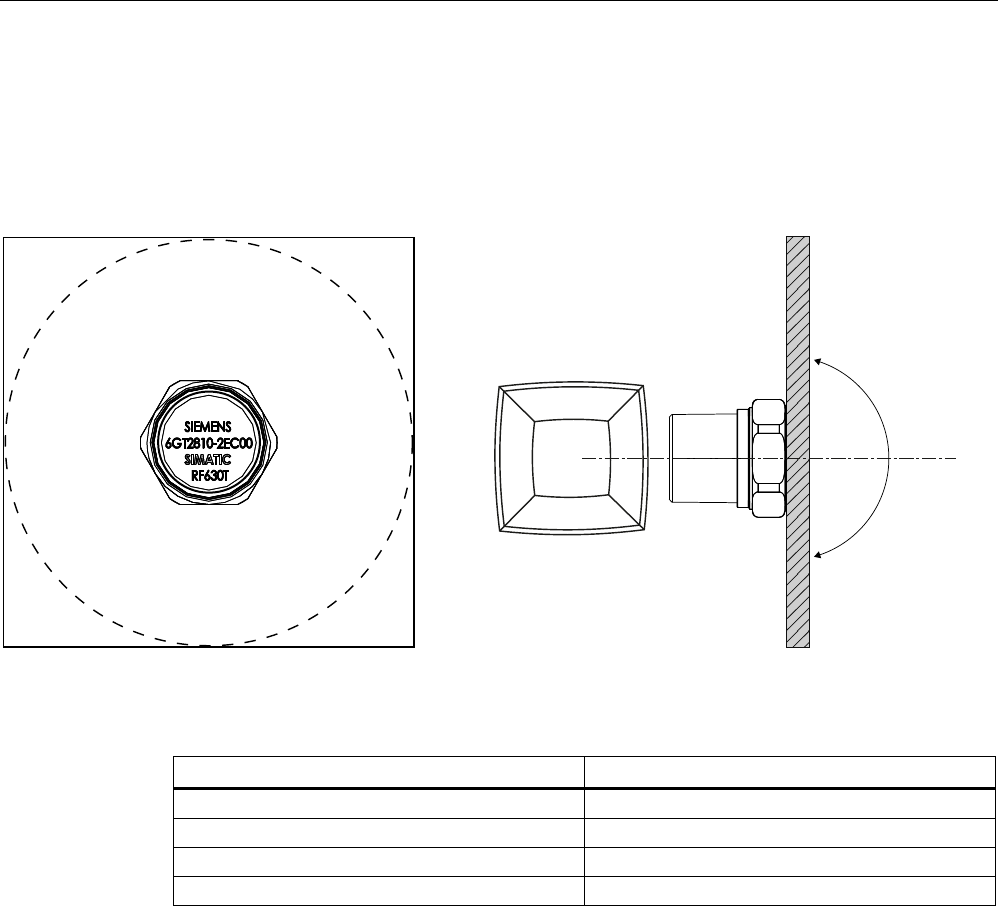
7.7.3.2 Reading range when mounted on flat metallic carrier plates
The transponder generally has linear polarization. The polarization axis runs as shown in the
diagram below. If the tag is centrally mounted on a flat metal plate, which may either be
almost square or circular, it can be aligned in any direction since the transmitting and
receiving RF660A antennas operate with circular polarization.
3RODUL]DWLRQD[LV
r
r
5)$
Figure 7-36 Optimum positioning of the transponder on a (square or circular) metal plate
Table 7- 20 Reading range on flat metallic carrier plates
Carrier plate material Reading range
Metal plate of at least Ø 300 mm 100 %
Metal plate Ø 150 mm Approx. 75 %
Metal plate Ø 120 mm Approx. 50 %
Metal plate Ø 85 mm Approx. 40 %
On rectangular carrier plates, the reading distance depends on the mounting orientation of
the transponder
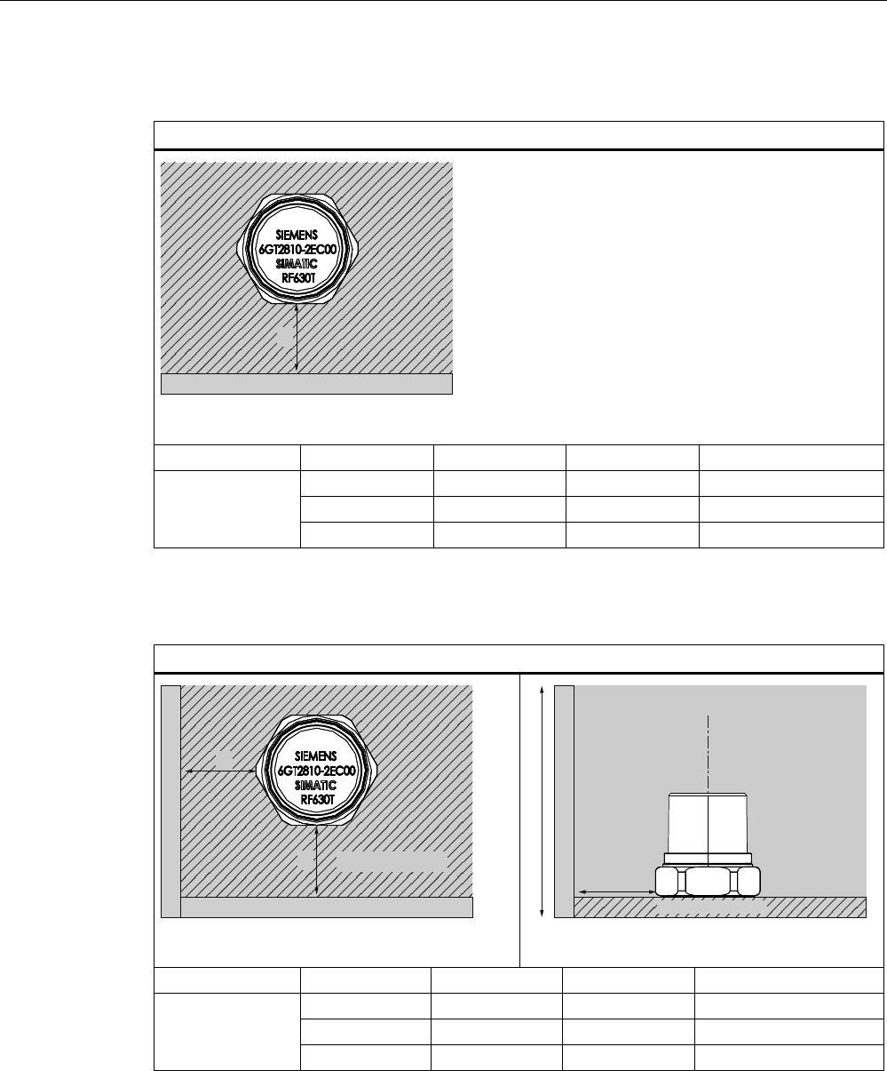
7.7.3.3 Influence of conducting walls on the reading range
If there are conducting walls or restrictions in the vicinity that could shade the radio field, a
distance of approx. 10 cm is recommended between the transponder and the wall. In
principle, walls have least influence if the polarization axis is vertical to the conducting wall.
Transponder/tags
7.7 SIMATIC RF630T
SIMATIC RF600
System Manual, 05/2012, J31069-D0171-U001-A13-7618 333
Reading range: One conducting wall
Influence on reading range when positioned against one conducting wall
&RQGXFWLQJZDOO
G
Top view
Distance d 20 mm 50 mm 100 mm
Approx. 40 % Approx. 40 % Approx. 90 % Wall height 20 mm
Approx. 40 % Approx. 90 % Approx. 90 % Wall height 50 mm
Reading range
Approx. 40 % Approx. 40 % Approx. 90 % Wall height 100 mm
Reading range: Two conducting walls
Influence on reading range when positioned against two conducting walls
&RQGXFWLQJZDOO
&RQGXFWLQJZDOO
0HWDOFDUULHU
G
G
G
3RODUL]DWLRQD[LV
0HWDOFDUULHU
&RQGXFWLQJZDOO
:DOOKHLJKW
Side view
Distance d 20 mm 50 mm 100 mm
Approx. 90 % Approx. 90 % Approx. 90 % Wall height 20 mm
Approx. 25 % Approx. 90 % Approx. 90 % Wall height 50 mm
Reading range
Approx. 25 % Approx. 90 % Approx. 90 % Wall height 100 mm
The values specified in the tables above must be complied with.
Transponder/tags
7.7 SIMATIC RF630T
SIMATIC RF600
334 System Manual, 05/2012, J31069-D0171-U001-A13-7618
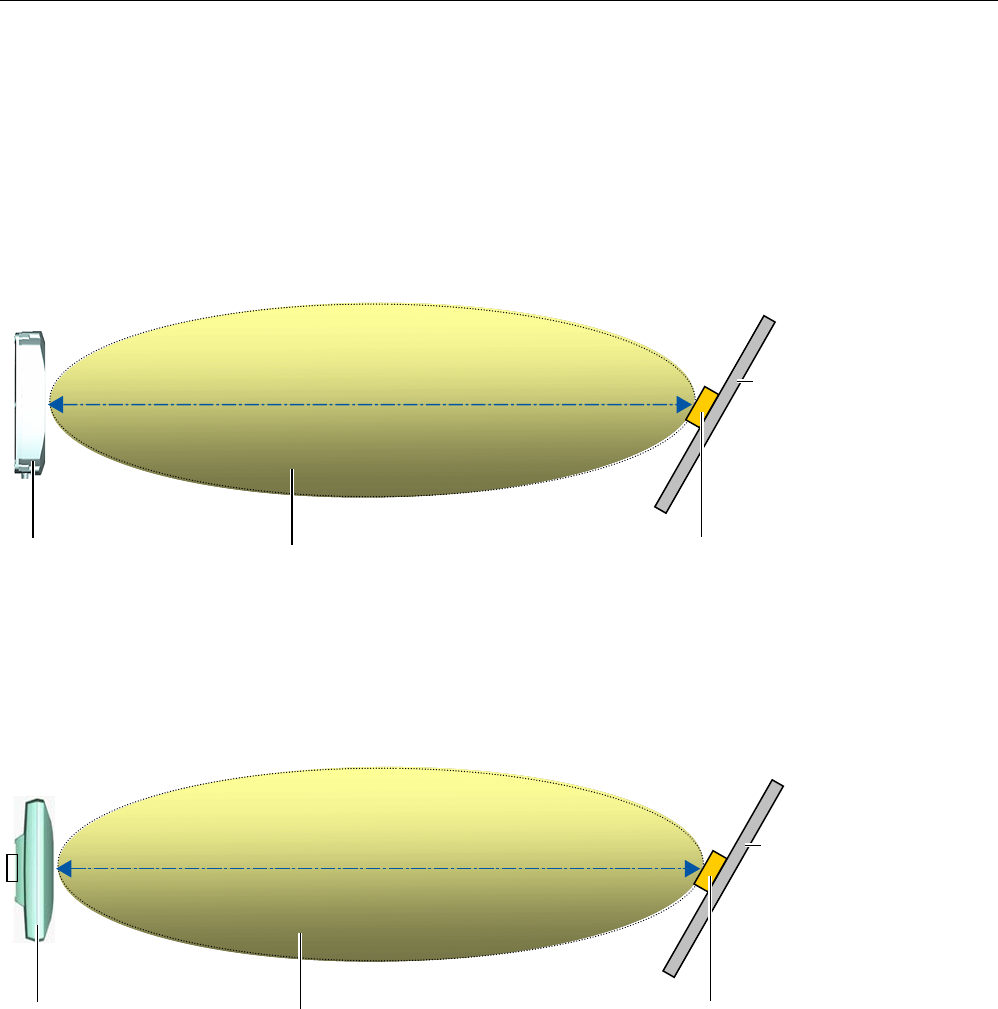
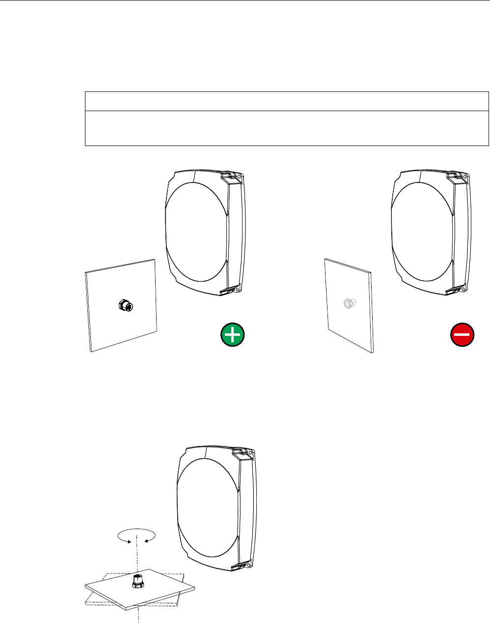
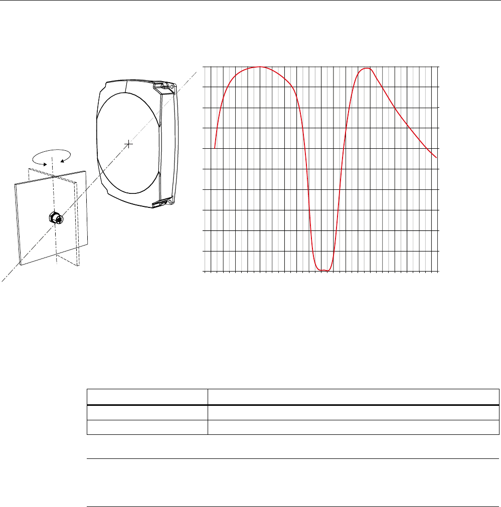
7.7.3.4 Directional radiation pattern of the transponder
Preferably, align the data carrier orthogonal to the transmitting antenna. If, however, the tag
including the metallic carrier plate is tilted, the reading range will be reduced.
NOTICE
Incorrect alignment of the transponder
When you align the transponder in parallel with the transmitting antenna, it cannot be read!
Optimum alignment of the transponder to the
transmitting antenna
Incorrect alignment of the transponder to the
transmitting antenna
Rotation about the polarization axis
If the transponder mounting surface is circular there is almost no change in the reading
range.
Transponder/tags
7.7 SIMATIC RF630T
SIMATIC RF600
System Manual, 05/2012, J31069-D0171-U001-A13-7618 335
Rotation of the mounting plane
$QJOHGHJUHHV
5DQJHSHUFHQWDJH
3RVLWLRQHGDWr
Figure 7-37 Characteristics of the transponder on rotation of the mounting plane
7.7.4 Mounting instructions
Properties Description
Type of installation M6 bolt fixing, spanner size 19 mm
Tightening torque (at room temperature) ≤ 6 Nm
Note
Make sure that the mounting surface is even when mounting the transponder. Electrical
contact between the mounting surface and the transponder is necessary.
Without a metal surface the transponder does not function.
7.7.5 Memory configuration of the transponder
The memory configuration of the transponder is described in the section SIMATIC memory
configuration of the RF600 transponders and labels (Page 270).

Transponder/tags
7.7 SIMATIC RF630T
SIMATIC RF600
336 System Manual, 05/2012, J31069-D0171-U001-A13-7618
7.7.6 Technical specifications
7.7.6.1 Mechanical data
Property Description
Dimensions (D x H) 21 mm x 21 mm (without thread), tolerance 1 mm
spanner size 19 mm
Design Plastic enclosure: PA 6.6 GF, silicone-free
Thread: Stainless steel
Weight approx. 22 g
Installation directly on metal without spacing
7.7.6.2 Electrical data
Description Property
Europe USA / Canada
Air interface According to ISO 18 000-6 C According to ISO 18 000-6 C
Frequency range 865 … 868 MHz 902 MHz ... 928 MHz 1)
Necessary transmit power 2 W (ERP) 4 W (EIRP)
Reading range
Mounting on metal 2)
at least 1.2 m, typically 1.5 m at least 1.2 m, typically 1.5 m
Writing range
Mounting on metal 2)
at least 0.8 m
typically 1.2 m
at least 0.8 m
typically 1.2 m
Polarization type Linear Linear
Minimum distance to transmit
antenna
Approx. 0.15 m Approx. 0.15 m
Energy source Energy via electro-magnetic field via
antenna, no battery required
Energy via electro-magnetic field via
antenna, no battery required
Multi-tag capability Yes, minimum distance between data
carriers ≥ 50 mm 3)
Yes, minimum distance between data
carriers ≥ 50 mm 3)
1) Reduction of range to about 70% at the band limits 902 MHz or 928 MHz; detection is
guaranteed at 915 MHz due to frequency hopping procedure.
2) Mounting on a flat surface with a diameter of at least 150 mm and at room temperature.
3) When the minimum distances are not reached, there is a reduction in the maximum read
and write distances of the transponder.
Transponder/tags
7.7 SIMATIC RF630T
SIMATIC RF600
System Manual, 05/2012, J31069-D0171-U001-A13-7618 337
7.7.6.3 Memory specifications
Property Description
Type EPC Class 1 Gen 2
EPC code 96 bits/240 bits
User memory 64 bytes
TID 64 bits
Memory organization
Reserved (passwords) 64 bits
Protocol ISO 18000-6C
Data retention time 10 years
Read cycles Unlimited
Write cycles Minimum at +22 °C 100 000
7.7.6.4 Environmental conditions
Property Description
Temperature range during operation -25 °C to +85 °C
Temperature range during storage -40 °C to +125 °C
Shock
Vibration
compliant with EN 60721-3-7 Class 7 M3
100 g, 1)
20 g, 1)
Torsion and bending load Not permissible
Degree of protection IP68 according to EN 60529:
(45 minutes. Immersion in water; water depth
1 m from
top edge of enclosure at +20 °C)
IPx9K according to DIN 40005-9
(steam jet-air ejector: 150 mm;
10 to 15 l/min; 100 bar; 75 °C)
1) The values for shock and vibration are maximum values and must not be applied continuously.

Transponder/tags
7.7 SIMATIC RF630T
SIMATIC RF600
338 System Manual, 05/2012, J31069-D0171-U001-A13-7618
7.7.6.5 Chemical resistance of the transponder
The following table provides an overview of the chemical resistance of the plastic cap of the
transponder made of PA 6.6 GF. Different values apply to the stainless steel bolt head. It
must be emphasized that the plastic enclosure is extremely resistant to chemicals in
automobiles (e.g.: oil, grease, diesel fuel, gasoline) which are not listed separately.
Concentration 20 °C 60 °C
Ammonia, w. conc. + +
20 + +
Benzol + +
Bleach solution (12.5 % effective chlorine) - ᅳ
Butane, gas, liquid + 1) Nothing
specified
Butyl acetate (acetic acid butyl ester) + 1) Nothing
specified
Calcium chloride, saturated 10% solution + ○
Chlorine ᅳ ᅳ
Chrome baths, tech. ᅳ ᅳ
Iron salts, w. k. g. - -
Acetic acid, w. 10 ○ ᅳ
Ethyl alcohol, w., undenaturated 40 + Nothing
specified
Formaldehyde 30 + Nothing
specified
Formalin + Nothing
specified
Glycerine + Nothing
specified
Isopropanol + +
Potassium hydroxide, w. 10-15 % ○ Nothing
specified
Magnesium salts, w. + 1) Nothing
specified
Methyl alcohol, w. 50 + Nothing
specified
Lactic acid, w. + ᅳ
Sodium carbonate, w. (soda) + Nothing
specified
Sodium chloride, w. ○ Nothing
specified
Sodium hydroxide 10 % + Nothing
specified
Nitrobenzol ○ 1) Nothing
specified
Phosphoric acid 10 - -
Transponder/tags
7.7 SIMATIC RF630T
SIMATIC RF600
System Manual, 05/2012, J31069-D0171-U001-A13-7618 339
Concentration 20 °C 60 °C
Propane + Nothing
specified
Nitric acid 10 - ᅳ
Hydrochloric acid 10 - ᅳ
Sulphur dioxide Low ○ Nothing
specified
Sulphuric acid 25 - ᅳ
10 - ᅳ
Hydrogen sulphide Dry + -
Carbon tetrachloride 1-4 % + Nothing
specified
1) Nothing specified for stainless steel
Abbreviations
+ Resistant
○ Limited resistance
ᅳ Not resistant
w. Aqueous solution
k. g. Cold saturated
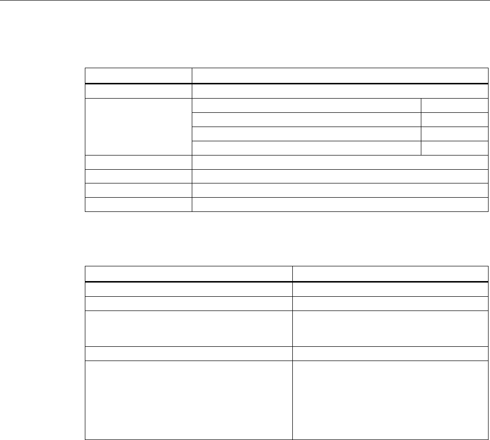
7.7.7 Certificates and approvals
Table 7- 21 6GT2810-2EC00 - RF630T UHF Tool Tag - Europe
Certificate Description
Conformity with R&TTE directive
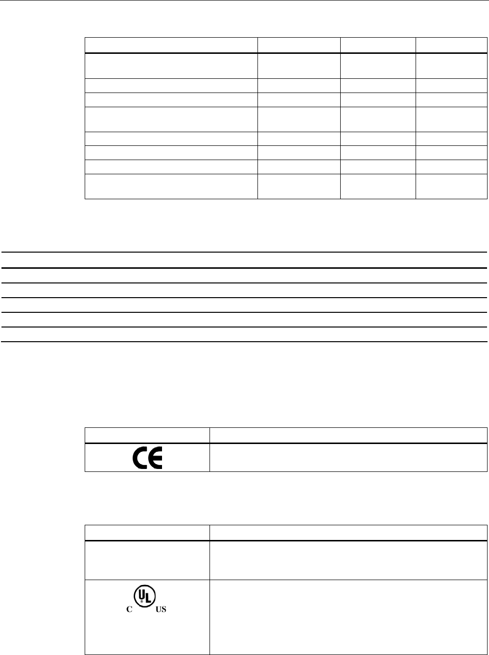
Table 7- 22 6GT2810-2EC10 - RF630T Gen 2 UHF Tool Tag - USA / Canada
Standard
FCC
Federal Communications
Commission
Passive labels and transponders comply with the valid regulations;
certification is not required.
This product is UL-certified for the USA and Canada.
It meets the following safety standard(s):
• UL508 - Industrial Control Equipment
• CSA C22.2 No. 142 - Process Control Equipment
• UL Report E 120869
Transponder/tags
7.7 SIMATIC RF630T
SIMATIC RF600
340 System Manual, 05/2012, J31069-D0171-U001-A13-7618
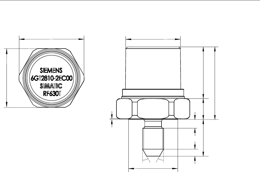
7.7.8 Dimension drawing
r r
0
Figure 7-38 SIMATIC RF630T
Units of measurement: All dimensions in mm
General tolerances in accordance with DIN ISO 2768f.
Transponder/tags
7.8 SIMATIC RF640T Gen 2
SIMATIC RF600
System Manual, 05/2012, J31069-D0171-U001-A13-7618 341
7.8 SIMATIC RF640T Gen 2
7.8.1 Characteristics
The SIMATIC RF640T Gen 2 transponder is a passive (i.e. battery-free) and maintenance-
free, round-shaped data carrier. It operates based on the UHF Class 1 Gen 2 technology
and is used to save the "Electronic Product Code" (EPC) of 96 bits/240 bits. The transponder
also has a 512-bit user memory.
Fields of application are industrial asset management, RF identification of tools, containers
and metallic equipment.
The tool tag is small and rugged and suitable for industrial applications with degree of
protection IP68. It is highly resistant to oil, grease and cleaning agents.
Preferably the SIMATIC RF640T is to be mounted direct on a flat metal surface of at least
150 mm diameter where it achieves a typical sensing distance of 4 m.
SIMATIC RF640T Gen 2 transponder Features
Application Identification tasks in rugged industrial
environments
Europe USA / Canada Frequency versions
868 MHz 915 MHz
Air interface according to ISO 18000-6C
Polarization Linear
Memory EPC 96 bit/240 bit
Add-on-memory 64 bytes
Typically 4.0 m in connection with:
• RF640R/RF670R reader and
• RF660A antennas
typically 3.6 m in conjunction with:
• RF640R with integrated antenna
Typically 2 m in connection with:
• RF620R/RF630R reader and
• RF660A antenna
Reading / writing range
Typically 2 m in connection with:
• RF620R with integrated antenna
Installation Suitable for direct mounting on conductive
materials (preferably metal)
Transponder/tags
7.8 SIMATIC RF640T Gen 2
SIMATIC RF600
342 System Manual, 05/2012, J31069-D0171-U001-A13-7618
7.8.2 Ordering data
Ordering data Order number
SIMATIC RF640T Gen 2 (Europe)
• Frequency 865 MHz to 868 MHz
• EPC 96 bits/240 bits
• 64-byte user memory
• -25 °C to +85 °C operating temperature
• Dimensions (D x H) 50 mm x 8 mm
6GT2810-2DC00
SIMATIC RF640T Gen 2 (USA/Canada)
• Frequency 902 MHz to 928 MHz
• EPC 96 bits/240 bits
• 64-byte user memory
• -25 °C to +85 °C operating temperature
• Dimensions (D x H) 50 mm x 8 mm
6GT2810-2DC10
7.8.3 Planning the use
7.8.3.1 Optimum antenna/transponder positioning with plane mounting of the transponder on
metal
Example of optimum antenna/transponder positioning
7UDQVSRQGHU
5)7
0HWDOFDUULHU
5)UHDGHU $QWHQQDILHOG
:ULWLQJUHDGLQJUDQJHVHHWHFKQLFDOGDWD
6HQGDQGUHFHLYH
Figure 7-39 Example of optimum antenna/transponder positioning with RF600 readers and an RF600 antenna
Transponder/tags
7.8 SIMATIC RF640T Gen 2
SIMATIC RF600
System Manual, 05/2012, J31069-D0171-U001-A13-7618 343
7.8.3.2 Reading range when mounted on flat metallic carrier plates
The transponder generally has linear polarization. The polarization axis runs as shown in the
diagram below. If the tag is centrically mounted on a flat metal plate, which may either be
almost square or circular, it can be aligned in any direction since the transmitting and
receiving RF660A antennas operate with circular polarization.
3RODUL]DWLRQD[LV
6TXDUH
PHWDOFDUULHUSODWH
&LUFXODUPHWDO
FDUULHUSODWH
r
Figure 7-40 Optimum positioning of the transponder on a (square or circular) metal plate
Table 7- 23 Reading range on flat metallic carrier plates
Carrier plate material Reading range
Metal plate of at least Ø 150 mm 100%
Metal plate Ø 120 mm Approx. 80%
Metal plate Ø 85 mm Approx. 55%
Metal plate Ø 65 mm Approx. 40%
On rectangular carrier plates, the reading distance depends on the mounting orientation of
the transponder.
Transponder/tags
7.8 SIMATIC RF640T Gen 2
SIMATIC RF600
344 System Manual, 05/2012, J31069-D0171-U001-A13-7618
7.8.3.3 Reading range when mounted on non-metallic carriers
The transponder is generally designed for mounting on metallic objects which provide the
conditions for the maximum reading ranges.
Table 7- 24 Reading range on non-metallic carriers
Carrier plate material Reading range
Transponder on wooden carrier Approx. 40%
Transponder on plastic carrier Approx. 35%
Transponder on plastic mineral water bottle Approx. 55%
Transponder without base Approx. 30%
100% reading distance refers to a metal plate of at least 150 mm diameter.
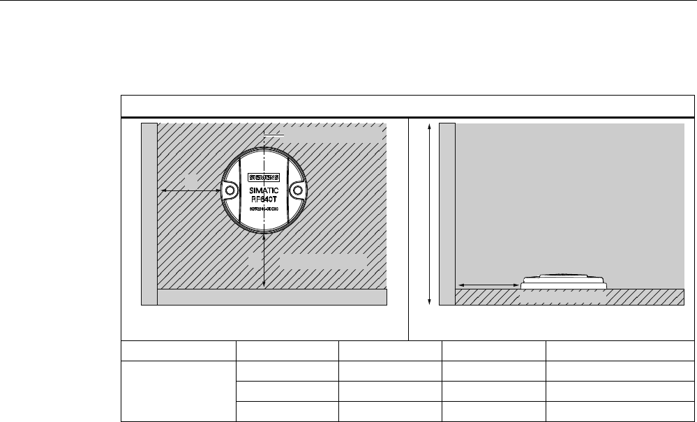
7.8.3.4 Influence of conducting walls on the reading range
If there are conducting walls or restrictions in the vicinity that could affect the radio field, a
distance of approx. 10 cm is recommended. In principle, walls have least influence if the
polarization axis is orthogonal to the wall.
Reading range: One conducting wall
Influence on reading range when positioned against one conducting wall
G
&RQGXFWLQJZDOO
3RODUL]DWLRQD[LV
Top view
Distance d 20 mm 50 mm 100 mm
Approx. 90 % Approx. 90 % Approx. 95 % Wall height 20 mm
Approx. 80 % Approx. 90 % Approx. 90 % Wall height 50 mm
Reading range
Approx. 70 % Approx. 75 % Approx. 90 % Wall height 100 mm
Transponder/tags
7.8 SIMATIC RF640T Gen 2
SIMATIC RF600
System Manual, 05/2012, J31069-D0171-U001-A13-7618 345
Reading range: Two conducting walls
Influence on reading range when positioned against two conducting walls
G
G
&RQGXFWLQJZDOO
&RQGXFWLQJZDOO
3RODUL]DWLRQD[LV
0HWDOFDUULHU
Top view
G
0HWDOFDUULHU
&RQGXFWLQJZDOO
:DOOKHLJKW
&RQGXFWLQJ
ZDOO
Side view
Distance d 20 mm 50 mm 100 mm
Approx. 75 % Approx. 90 % Approx. 90 % Wall height 20 mm
Approx. 50 % Approx. 45 % Approx. 80 % Wall height 50 mm
Reading range
Approx. 40 % Approx. 45 % Approx. 75 % Wall height 100 mm
The values specified in the tables above are guide values.
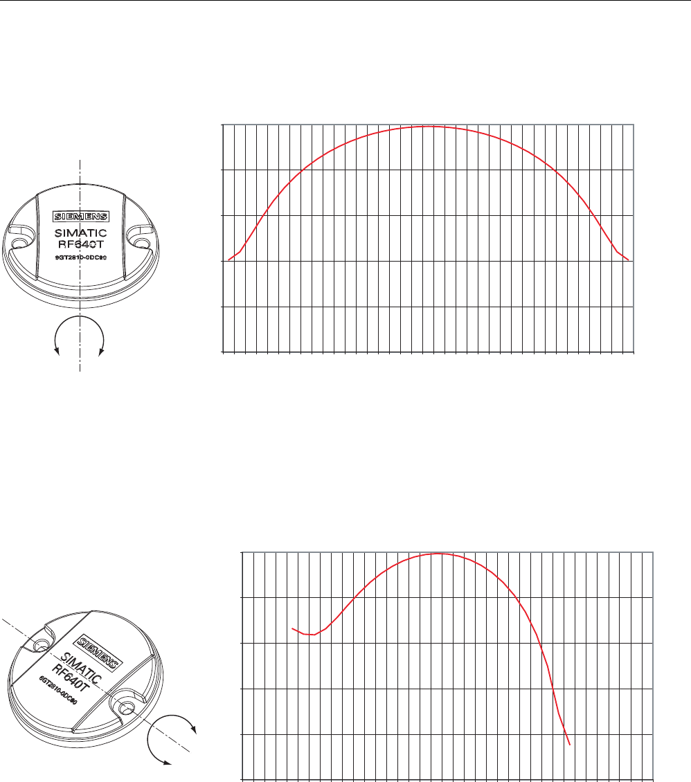
7.8.3.5 Directional radiation pattern of the transponder
Preferably, align the tag parallel to the transmitting antenna. If, however, the tag including
the metallic carrier plate is tilted, the reading range will be reduced.
Transponder/tags
7.8 SIMATIC RF640T Gen 2
SIMATIC RF600
346 System Manual, 05/2012, J31069-D0171-U001-A13-7618
Rotation about the polarization axis
-25
-20
-15
-10
-5
0
-90 -80 -70 -60 -50 -40 -30 -20 -10 0 10 20 30 40 50 60 70 80 90
$QJOHGHJUHHV
*DLQG%U
Figure 7-41 Transponder characteristics when rotated about the polarization axis
Rotation orthogonal to the polarization axis
-25
-20
-15
-10
-5
0
-90 -80 -70 -60 -50 -40 -30 -20 -10 0 10 20 30 40 50 60 70 80 90
$QJOHGHJUHHV
*DLQG%U
Figure 7-42 Transponder characteristics when rotated orthogonally to the polarization axis (within the tag plane)
Transponder/tags
7.8 SIMATIC RF640T Gen 2
SIMATIC RF600
System Manual, 05/2012, J31069-D0171-U001-A13-7618 347
7.8.3.6 Use of the transponder in the Ex protection area
TÜV NORD CERT GmbH, appointed center no. 0044 as per Article 9 of the Directive
94/9/EC of the European Council of 23 March 1994, has confirmed the compliance with the
essential health and safety requirements relating to the design and construction of
equipment and protective systems intended for use in hazardous areas as per Annex II of
the Directive.
The essential health and safety requirements are satisfied in accordance with standards
EN 60079-0: 2004, EN 60079-11: 2007, IEC 61241-0: 2004 and IEC 61241-11: 2005.
Identification
The identification is as follows:
II 2 G Ex ib IIC T6 to T3 or
II 2 D Ex ibD 21 T140°C,
-25 °C < Ta°< +85 °C
7.8.3.7 Use of the transponder in hazardous areas for gases
Temperature class delineation for gases
The temperature class of the transponder for hazardous areas depends on the ambient
temperature range:
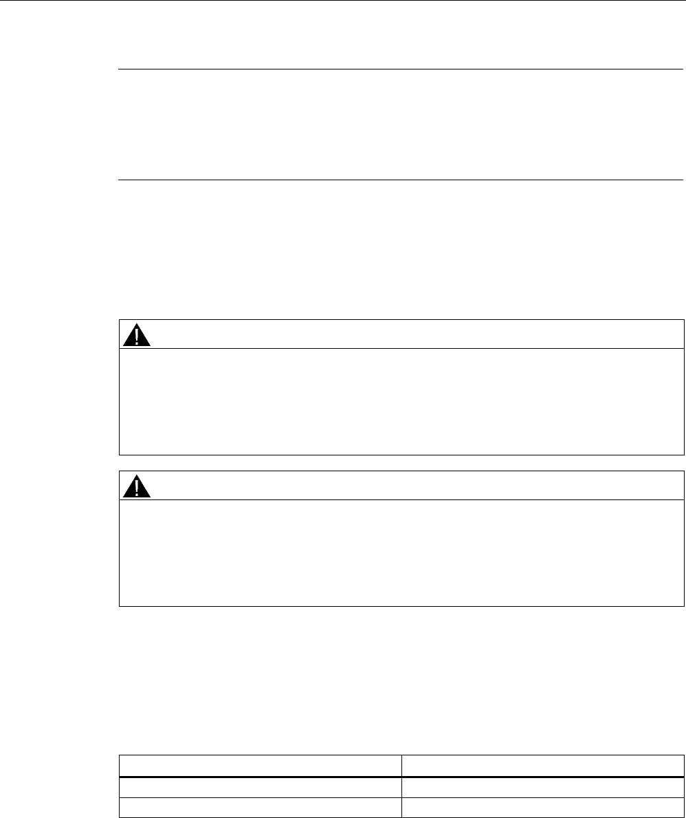
Ambient temperature range Temperature class
-25 °C to +85 °C T3
-25 °C to +60 °C T4
-25 °C to +40 °C T5
-25 °C to +30 °C T6

Transponder/tags
7.8 SIMATIC RF640T Gen 2
SIMATIC RF600
348 System Manual, 05/2012, J31069-D0171-U001-A13-7618
WARNING
Ignitions of gas-air mixtures
When using the RF640T transponder, check to ensure that the temperature class is
observed in respect of the requirements of the area of application
Non-compliance with the permitted temperature ranges while using the transponder can
lead to ignitions of gas-air mixtures.
WARNING
Ignitions of gas-air mixtures
The maximum transmitting power of the transmitter used to operate the transponder must
not exceed 2 W.
Non-compliance with the permissible transmitting power can lead to ignitions of gas-air
mixtures.
7.8.3.8 Use of the transponder in hazardous areas for dusts
The equipment is suitable for dusts whose ignition temperatures for a dust layer of 5 mm are
higher than 210 °C (smoldering temperature). With the ignition temperature specified
according to IEC 61241-0 and IEC 61241-11 according to the type of ignition protection iD,
the smoldering temperature of the dust layer is referenced in this case.
Temperature class delineation for dusts
Ambient temperature range Temperature value
-25 °C < Ta < +85 °C T140 °C
WARNING
Ignitions of dust-air mixtures
When using the RF640T transponder, check to ensure that the temperature values are
complied with in connection with the requirements of the application area.
Non-compliance with the permitted temperature ranges while using the transponder can
lead to ignitions of dust-air mixtures.
Transponder/tags
7.8 SIMATIC RF640T Gen 2
SIMATIC RF600
System Manual, 05/2012, J31069-D0171-U001-A13-7618 349
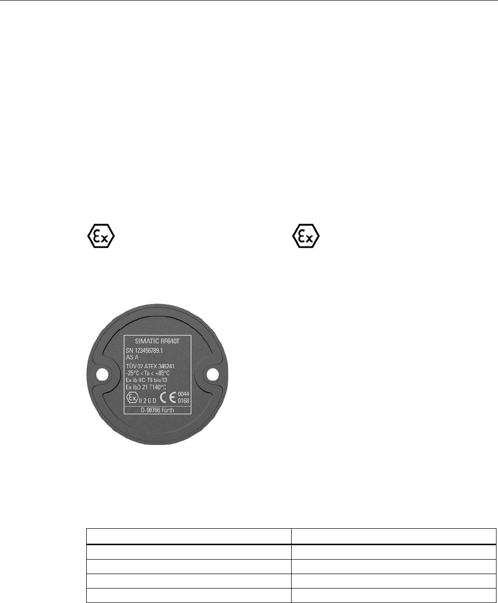
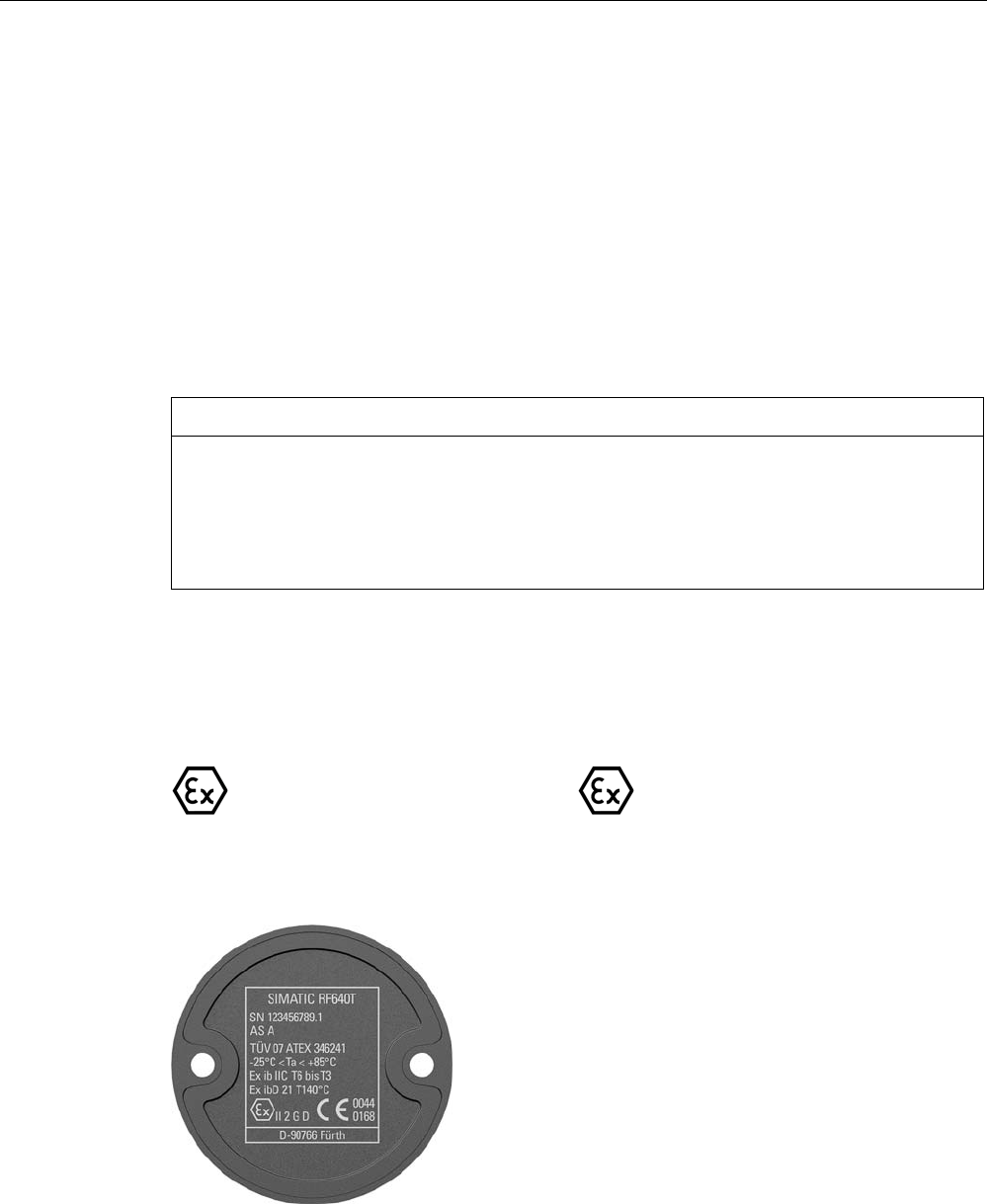
7.8.3.9 Use of the transponder in the Ex protection area
TÜV NORD CERT GmbH, appointed center no. 0044 as per Article 9 of the Directive
94/9/EC of the European Council of 23 March 1994, has confirmed the compliance with the
essential health and safety requirements relating to the design and construction of
equipment and protective systems intended for use in hazardous areas as per Annex II of
the Directive.
The essential health and safety requirements are met in accordance with standards
EN 60079-0: 2009, EN 60079-11: 2007 and IEC 61241-11: 2006.
This allows the RF640T transponder to be used in hazardous areas for gases, for the device
category 2 G and equipment group IIC, or alternatively in hazardous areas for dusts, for the
device category 2 D and equipment group IIIB.
NOTICE
Readability of the serial number on the type plate
When using the transponder, make sure that the serial number can be read. The serial
number is lasered and can be hidden by paint or other materials making it illegible.
The customer is responsible for making sure that the serial number of a transponder for the
hazardous area can be read at all times.
Identification
The identification is as follows:
II 2 G Ex ib IIC T6 to T3 or
II 2 D Ex ib IIIB T160°C,
-25 °C < Ta°< +85 °C
7.8.3.10 Use of the transponder in hazardous areas for gases
Transponder/tags
7.8 SIMATIC RF640T Gen 2
SIMATIC RF600
350 System Manual, 05/2012, J31069-D0171-U001-A13-7618
Note
Transponder labeling
The labeling of the front of the transponder shown above is an example and can vary
between batches produced at different times.
This does not affect the hazardous area marking.
Temperature class delineation for gases
The temperature class of the transponder for hazardous atmospheres (gases) depends on
the ambient temperature and the radiated power of an antenna in the 865 - 868 MHz
frequency band within the hazardous area.
WARNING
Ignitions of gas-air mixtures
When using the RF640T transponder, check to ensure that the temperature class is
observed in respect of the requirements of the area of application
Non-compliance with the permitted temperature ranges while using the transponder can
lead to ignitions of gas-air mixtures.
WARNING
Ignitions of gas-air mixtures
The maximum transmitting power of the transmitter used to operate the transponder must
not exceed 2 W.
Non-compliance with the permissible transmitting power can lead to ignitions of gas-air
mixtures.
Temperature class assignment for gases and a radiated power less than 100 mW ERP
If the radiated power of an antenna radiating into the hazardous area or located in the
hazardous area and operating in the 865 - 868 MHz frequency band cannot exceed the
value 100 mW, the temperature class assignment is as follows:
Ambient temperature range Temperature class
-25 °C to +85 °C T5
-25 °C to +76 °C T6
Transponder/tags
7.8 SIMATIC RF640T Gen 2
SIMATIC RF600
System Manual, 05/2012, J31069-D0171-U001-A13-7618 351
Temperature class assignment for gases and a radiated power less than 500 mW ERP
If the radiated power of an antenna radiating into the hazardous area or located in the
hazardous area and operating in the 865 - 868 MHz frequency band cannot exceed the
value 500 mW, the temperature class assignment is as follows:
Ambient temperature range Temperature class
-25 °C to +85 °C T4
-25 °C to +77 °C T5
-25 °C to +62 °C T6
Temperature class assignment for gases and radiated power for 2000 mW ERP
If the radiated power of an antenna radiating into the hazardous area or located in the
hazardous area and operating in the 865 - 868 MHz frequency band cannot exceed the
value 2000 mW, the temperature class assignment is as follows:
Ambient temperature range Temperature class
-25 °C to +85 °C T3
-25 °C to +65 °C T4
-25 °C to +25 °C T5
-25 °C to +10 °C T6
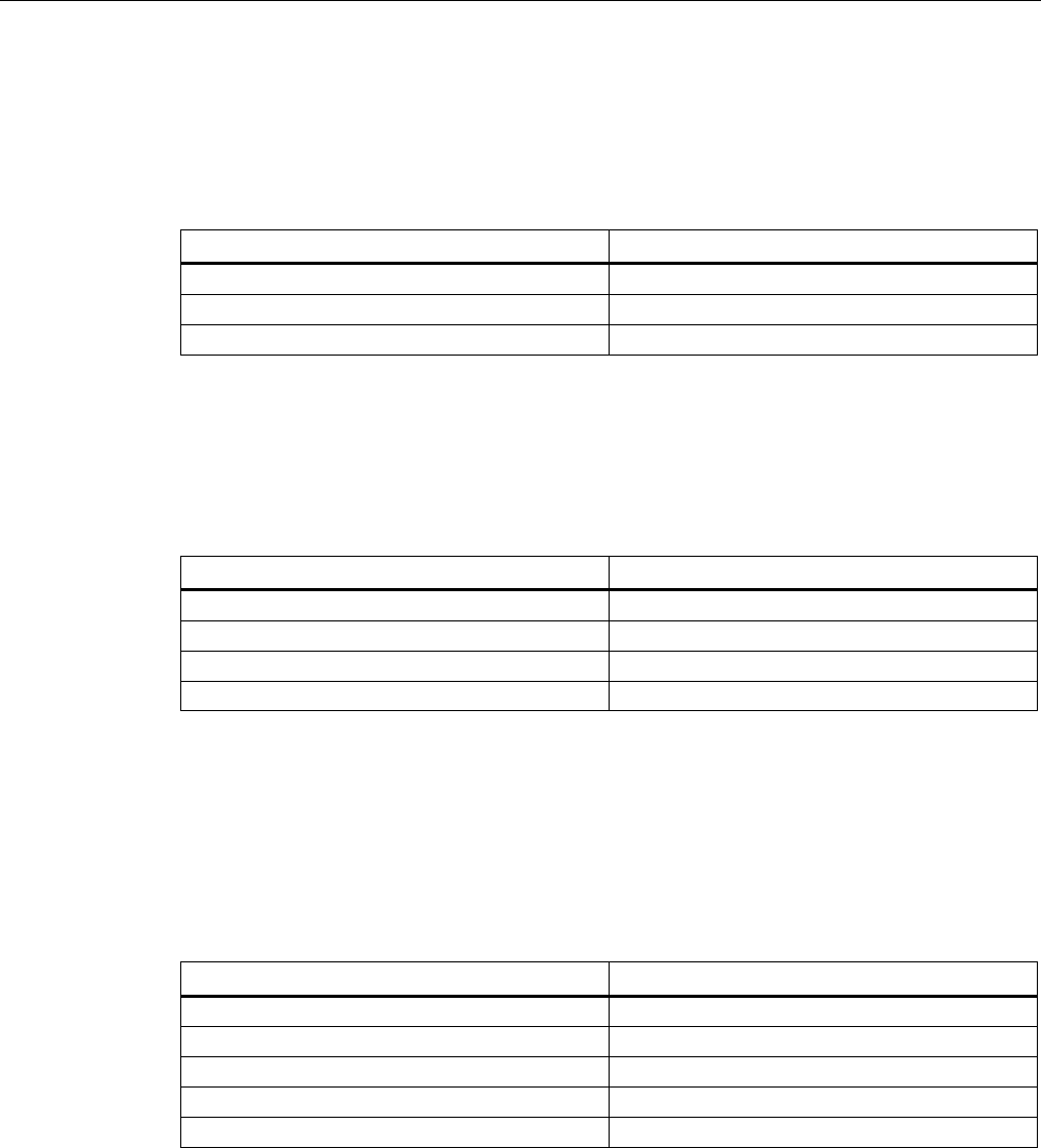
Temperature class assignment for gases and a radiated power of 10 mW to 2000 mW ERP
If the radiated power of an antenna radiating into the hazardous area or of an antenna
located in the hazardous area in the 865 - 868 MHz frequency band cannot exceed the
radiated power selected in the following diagram, the maximum permitted ambient
temperature range can be found in the corresponding temperature function of the diagram.
This makes the following temperature class assignment valid:
Ambient temperature range Temperature class
-25 °C to +85 °C T2
-25 °C to +85 °C T3
-25 °C to Tmax (T4) °C T4
-25 °C to Tmax (T5) °C T5
-25 °C to Tmax (T6) °C T6
Transponder/tags
7.8 SIMATIC RF640T Gen 2
SIMATIC RF600
352 System Manual, 05/2012, J31069-D0171-U001-A13-7618
Figure 7-43 Maximum permitted ambient temperature depending on the radiated power
7.8.3.11 Use of the transponder in hazardous areas for dusts
The equipment is suitable for dusts whose ignition temperatures for a dust layer of 5 mm are
higher than 210 °C (smoldering temperature). The ignition temperature specified here
according to EN 60079-0 and EN 61241-11 for ignition protection type ib in this case
references the smoldering temperature of a layer of combustible flyings (ib IIIA) or
alternatively non-conductive dusts (ib IIIB).
Temperature class delineation for dusts
WARNING
Ignitions of dust-air mixtures
When using the RF640T transponder, check to ensure that the temperature values are
complied with in connection with the requirements of the application area.
Non-compliance with the permitted temperature ranges while using the transponder can
lead to ignitions of dust-air mixtures.
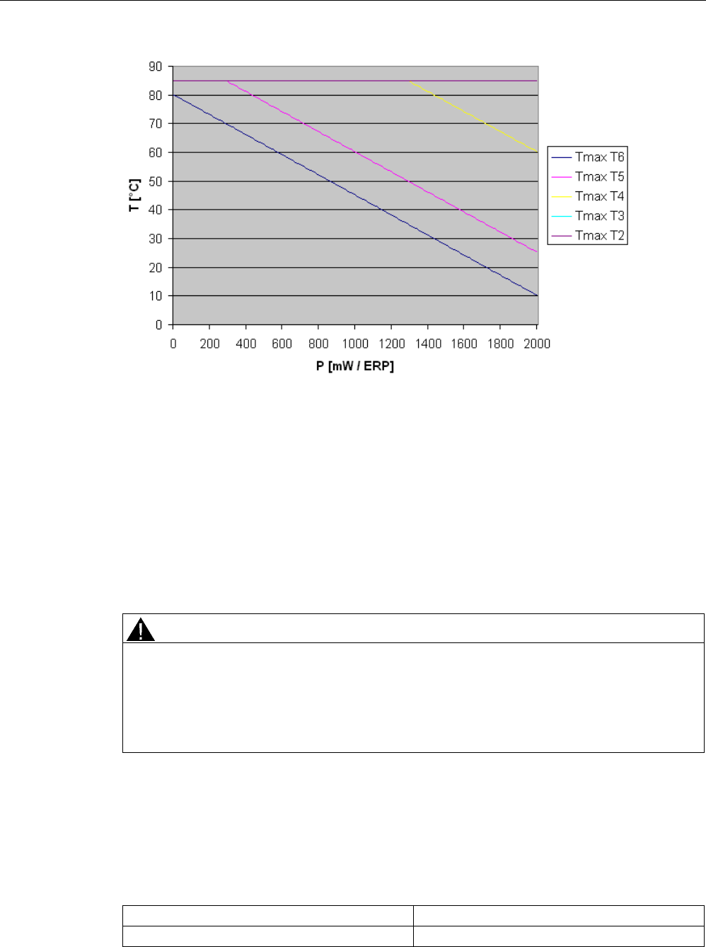
Temperature class assignment for dusts and a radiated power less than 100 mW ERP
If the radiated power of an antenna radiating into the hazardous area or located in the
hazardous area and operating in the 865 - 868 MHz frequency band cannot exceed the
value 100 mW, the temperature class assignment is as follows:
Ambient temperature range Temperature value
-25 °C < Ta < +85 °C T94 °C
Transponder/tags
7.8 SIMATIC RF640T Gen 2
SIMATIC RF600
System Manual, 05/2012, J31069-D0171-U001-A13-7618 353
Temperature class assignment for dusts and a radiated power less than 500 mW ERP
If the radiated power of an antenna radiating into the hazardous area or located in the
hazardous area and operating in the 865 - 868 MHz frequency band cannot exceed the
value 500 mW, the temperature class assignment is as follows:
Ambient temperature range Temperature value
-25 °C < Ta < +85 °C T108 °C
Temperature class assignment for dusts and a radiated power less than 2000 mW ERP
If the radiated power of an antenna radiating into the hazardous area or located in the
hazardous area and operating in the 865 - 868 MHz frequency band cannot exceed the
value 2000 mW, the temperature class assignment is as follows:
Ambient temperature range Temperature value
-25 °C < Ta < +85 °C T160 °C
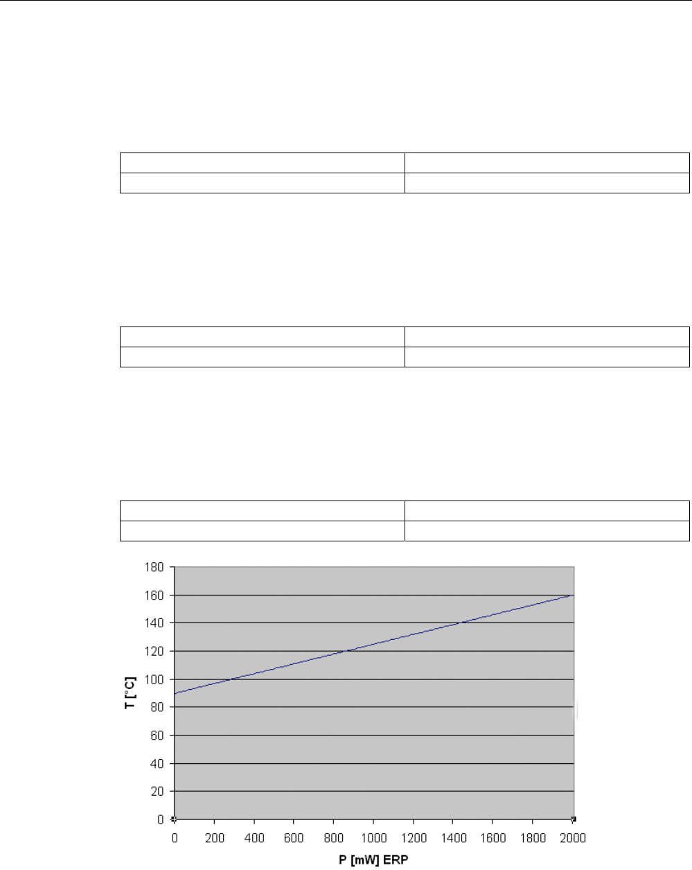
Temperature class assignment for dusts and a radiated power of 10 mW ERP to 2000 mW ERP
If the radiated power of an antenna radiating into the hazardous area or located in the
hazardous area and operating in the 865 - 868 MHz frequency band can be between the
values 10 mW ERP and 2000 mW ERP, the temperature class assignment is as follows:
Ambient temperature range Temperature value
-25 °C < Ta < +85 °C Tvalue °C (see diagram)
Figure 7-44 Maximum permitted ambient temperature depending on the radiated power
Transponder/tags
7.8 SIMATIC RF640T Gen 2
SIMATIC RF600
354 System Manual, 05/2012, J31069-D0171-U001-A13-7618
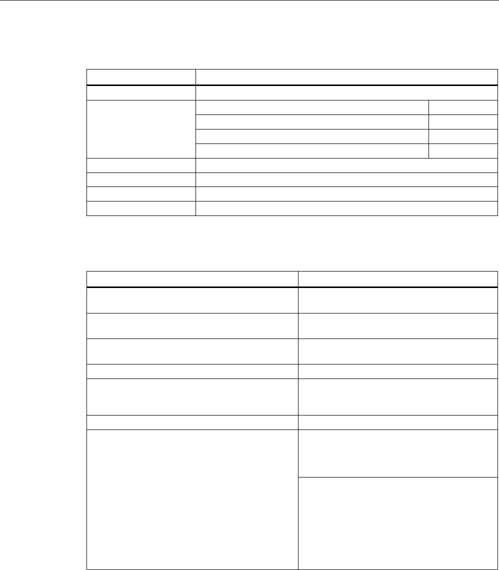
7.8.4 Mounting instructions
Properties Description
Type of installation Screw mounting ①, (M4 screws)
(two DIN 433 washers and two M4 hexagon socket head cap screws
DIN 6912)
Tightening torque (at room temperature) < 1.2 Nm
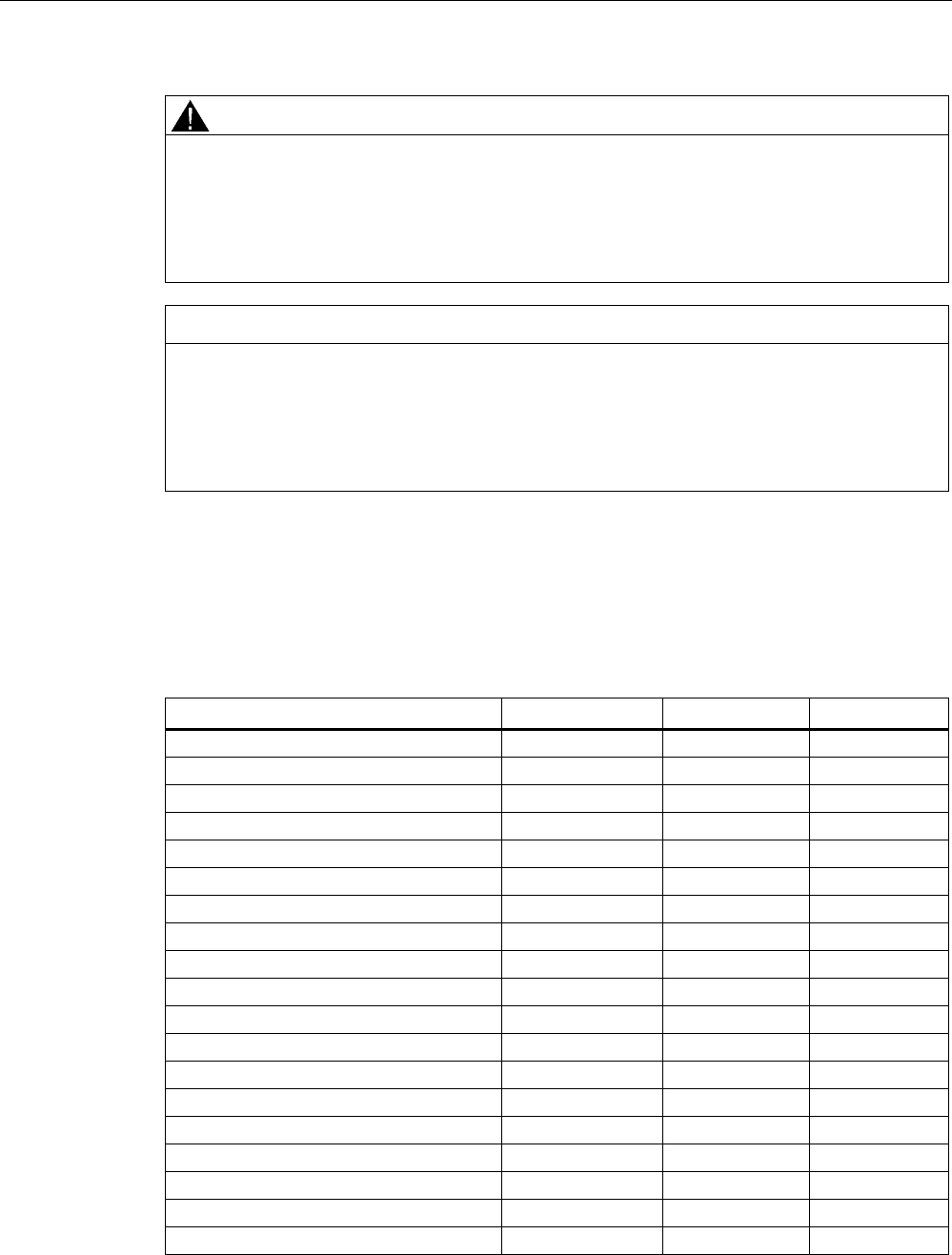
Figure 7-45 Screw mounting
Note
Make sure that the mounting surface is even when mounting the transponder.
7KHPRXQWLQJVXUIDFH
PXVWEHHYHQ
7.8.5 Memory configuration of the transponder
The memory configuration of the transponder is described in the section SIMATIC memory
configuration of the RF600 transponders and labels (Page 270).

Transponder/tags
7.8 SIMATIC RF640T Gen 2
SIMATIC RF600
System Manual, 05/2012, J31069-D0171-U001-A13-7618 355
7.8.6 Technical Specifications
7.8.6.1 Mechanical data
Property Description
Dimensions (D x H) 50 mm x 8 mm (+1 mm)
Design PCB with integrated antenna
Design Plastic enclosure (PA12), silicone-free
Weight approx. 13 g
Mounting on metal directly on metal without spacing
7.8.6.2 Electrical data
Description Property
Europe USA / Canada
Air interface According to ISO 18 000-6 C According to ISO 18 000-6 C
Frequency range 865 … 868 MHz 902 MHz ... 928 MHz 1)
Necessary transmit power 2 W (ERP) 4 W (EIRP)
Reading range
Mounting on metal 2)
at least 3 m
typically 4.0 m
at least 3 m
typically 4.0 m
Writing range
Mounting on metal 2)
at least 2 m
typically 3 m
at least 2 m
typically 3 m
Polarization type Linear Linear
Minimum distance to transmit
antenna
Approx. 0.2 m Approx. 0.2 m
Energy source Magnetic energy via antenna, without
battery
Magnetic energy via antenna, without
battery
Multi-tag capability Yes, minimum distance between data
carriers ≥ 50 mm 3)
Yes, minimum distance between data
carriers ≥ 50 mm 3)
1) Reduction of range to about 70% at the band limits 902 MHz or 928 MHz; recording is
guaranteed at 915 MHz due to frequency hopping procedure.
2) Mounting on a flat surface with a diameter of at least 150 mm
3) When the minimum distances are not reached, there is a reduction in the maximum read
and write distances of the transponder.
See also
Reading range when mounted on flat metallic carrier plates (Page 343)
Directional radiation pattern of the transponder (Page 345)
Transponder/tags
7.8 SIMATIC RF640T Gen 2
SIMATIC RF600
356 System Manual, 05/2012, J31069-D0171-U001-A13-7618
7.8.6.3 Memory specifications
Property Description
Type EPC Class 1 Gen 2
EPC code 96 bits/240 bits
User memory 64 bytes
TID 64 bits
Memory organization
Reserved (passwords) 64 bits
Protocol ISO 18000-6C
Data retention time 10 years
Read cycles Unlimited
Write cycles Minimum at +22 °C 100 000
7.8.6.4 Environmental conditions
Property Description
Temperature range when operating in non-
hazardous areas
-25 °C … 85 °C1)
Temperature range when operating in areas at risk
of a gas explosion with temperature class T3-T6
See alsoUse of the transponder in hazardous
areas for gases (Page 347) 2)
Temperature range when operating in areas at risk
of dust explosions with T140 °C
See alsoUse of the transponder in hazardous
areas for dusts (Page 348) 2)
Temperature range during storage -40 °C … 125 °C1)
Shock
Vibration
compliant with EN 60721-3-7 Class 7 M3
100 g, 3)
20 g, 3)
Torsion and bending load Not permissible
IP68 according to EN 60529:
(45 minutes. immersion in water; water depth
1 m from
top edge of housing at +20 °C)
Degree of protection
IP x9K according to EN 60529:
• Steam blaster nozzle distance 150 mm
• 10 ... 15 l of water per minute
• Pressure 100 bar
• Temperature 75 °C
• Test time 30 seconds
1) At temperatures above 70 °C the casing may distort slightly; this does not however cause
any impairment of function (mechanical or electrical).
2) Directive 94/9/EC of the European Council of 23 March 1994 must be complied with, see
also Chapter "Using the transponder in hazardous areas".
3) The values for shock and vibration are maximum values and must not be applied
continuously.
Transponder/tags
7.8 SIMATIC RF640T Gen 2
SIMATIC RF600
System Manual, 05/2012, J31069-D0171-U001-A13-7618 357
WARNING
Ignitions of gas-air or dust-air mixtures
When using the RF640T transponder, check to ensure that the temperature values are
observed in respect of the requirements of the hazardous area of application.
Non-compliance with the permitted temperature ranges while using the transponder can
lead to ignitions of gas-air or dust-air mixtures.
NOTICE
Damage to the surface of the housing
The values specified for the IP x9K test are maximum values and must not be applied
continuously.
Protracted loading of the transponder can lead to damage to the surface of the housing due
to high pressures.
7.8.6.5 Chemical resistance of the RF640T transponder
The following table gives an overview of the chemical composition of the data memory made
from polyamide 12. The plastic housing has a notably high resistance to chemicals used in
automobiles (e.g.: oil, grease, diesel fuel, gasoline) which are not listed separately.
Concentration 20 °C 60 °C
Battery acid 30 ○○ ᅳ
Ammonia gas ○○○○ ○○○○
Ammonia, w. conc. ○○○○ ○○○○
10 ○○○○ ○○○○
Benzol ○○○○ ○○○
Bleach solution (12.5 % effective chlorine) ○○ ᅳ
Butane, gas, liquid ○○○○ ○○○○
Butyl acetate (acetic acid butyl ester) ○○○○ ○○○○
Calcium chloride, w. ○○○○ ○○○
Calcium nitrate, w. k. g. ○○○○ ○○○
Chlorine ᅳ ᅳ
Chrome baths, tech. ᅳ ᅳ
Iron salts, w. k. g. ○○○○ ○○○○
Acetic acid, w. 50 ᅳ ᅳ
Ethyl alcohol, w., undenaturated 96 ○○○○ ○○○
50 ○○○○ ○○○○
Formaldehyde, w. 30 ○○○ ᅳ
10 ○○○○ ○○○
Formalin ○○○ ᅳ

Transponder/tags
7.8 SIMATIC RF640T Gen 2
SIMATIC RF600
358 System Manual, 05/2012, J31069-D0171-U001-A13-7618
Concentration 20 °C 60 °C
Glycerine ○○○○ ○○○○
Isopropanol ○○○○ ○○○
Potassium hydroxide, w. 50 ○○○○ ○○○○
Lysol ○○ ᅳ
Magnesium salts, w. k. g. ○○○○ ○○○○
Methyl alcohol, w. 50 ○○○○ ○○○○
Lactic acid, w. 50 ○○ ᅳ
10 ○○○ ○○
Sodium carbonate, w. (soda) k. g. ○○○○ ○○○○
Sodium chloride, w. k. g. ○○○○ ○○○○
Sodium hydroxide ○○○○ ○○○○
Nickel salts, w. k. g. ○○○○ ○○○○
Nitrobenzol ○○○ ○○
Phosphoric acid 10 ○ V
Propane ○○○○ ○○○○
Mercury ○○○○ ○○○○
Nitric acid 10 ○ ᅳ
Hydrochloric acid 10 ○ ᅳ
Sulphur dioxide Low ○○○○ ○○○○
Sulphuric acid 25 ○○ ᅳ
10 ○○○ ᅳ
Hydrogen sulphide Low ○○○○ ○○○○
Carbon tetrachloride ○○○○ ○○○○
Toluene ○○○○ ○○○
Detergent High ○○○○ ○○○○
Plasticizer ○○○○ ○○○○
Abbreviations
○○○○ Resistant
○○○ Virtually resistant
○○ Limited resistance
○ Less resistant
ᅳ Not resistant
w. Aqueous solution
k. g. Cold saturated