Siemens RF600R RFID UHF Reader User Manual SIMATIC RF600
Siemens AG RFID UHF Reader SIMATIC RF600
UserManual.wiki
>
Siemens
>
RF600R User Manual
>
User manual 05
Contents
1.
User manual 01
2.
User manual 02
3.
User manual 03
4.
User manual 04
5.
User manual 05
User manual 05
Navigation menu
Upload a User Manual
Namespaces
Wiki Guide
HTML
PDF
Info
Views
User Manual
Discussion / Help
Navigation
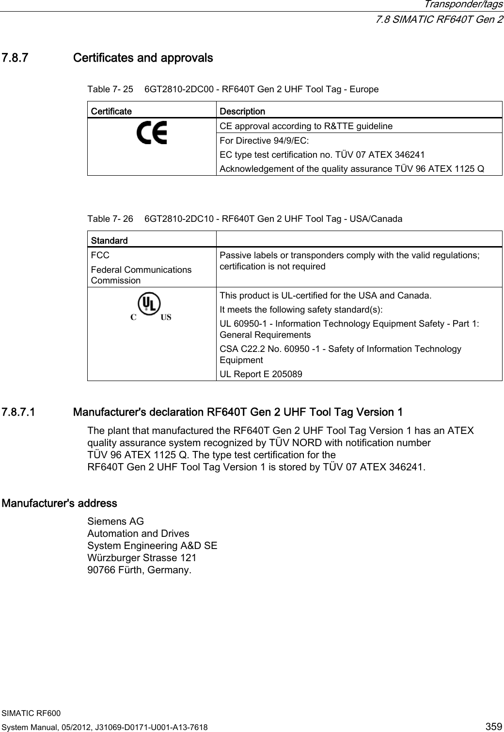
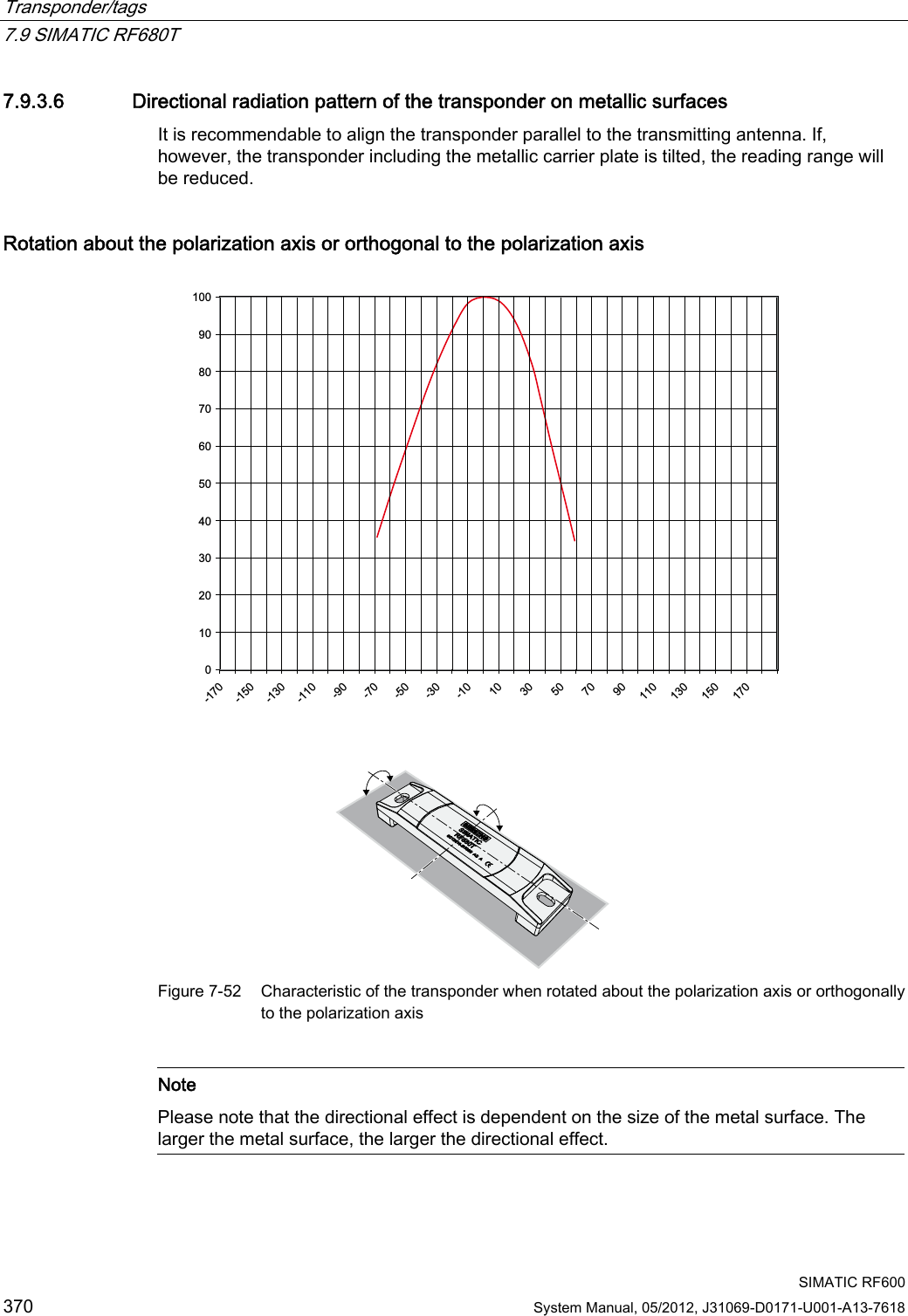
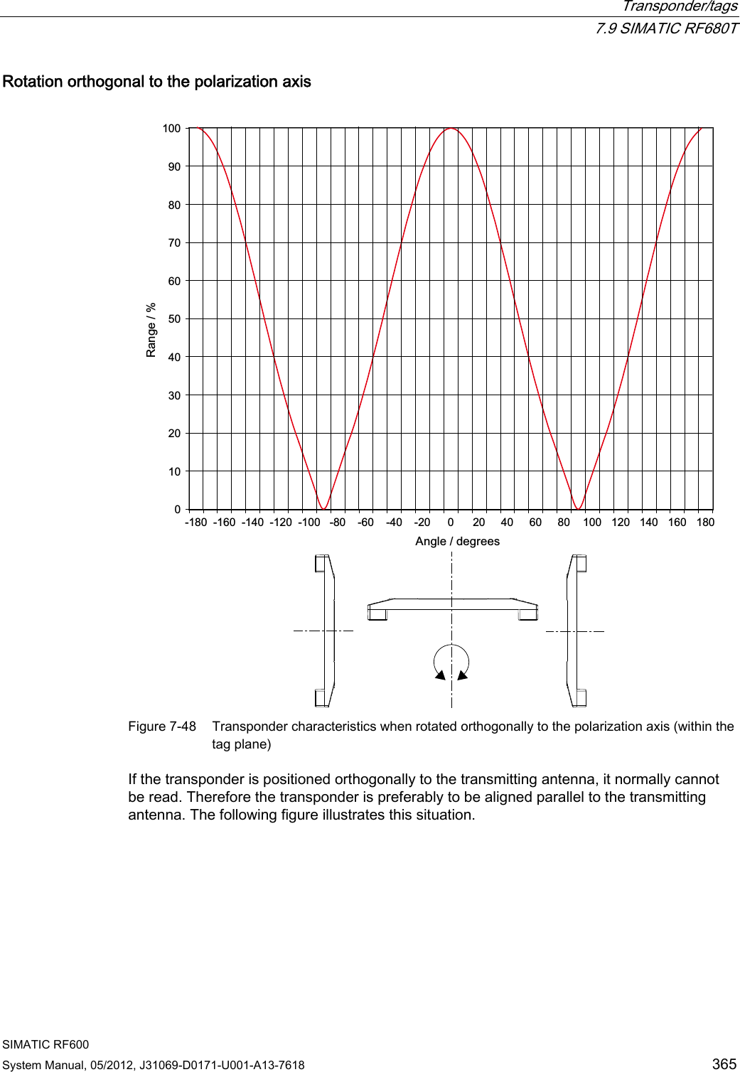
![Transponder/tags 7.9 SIMATIC RF680T SIMATIC RF600 364 System Manual, 05/2012, J31069-D0171-U001-A13-7618 7.9.3.2 Directional radiation pattern of the transponder on non-metallic surfaces It is recommendable to align the transponder parallel to the transmitting antenna. If, however, the transponder including the metallic carrier plate is tilted, the reading range will be reduced. Rotation about the polarization axis 3RODUL]DWLRQD[LV Figure 7-47 Rotation of the transponder about the polarization axis Generally the range does not change when the transponder without carrier material is rotated about the polarization axis.](https://usermanual.wiki/Siemens/RF600R.User-manual-05/User-Guide-1716294-Page-6.png)
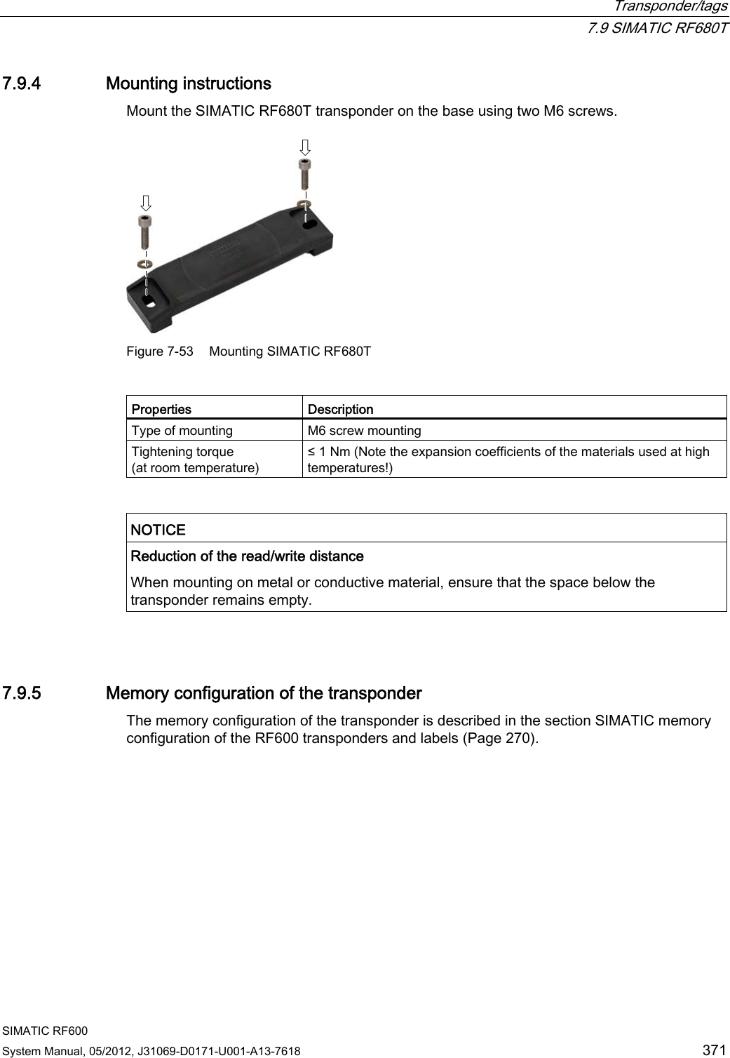
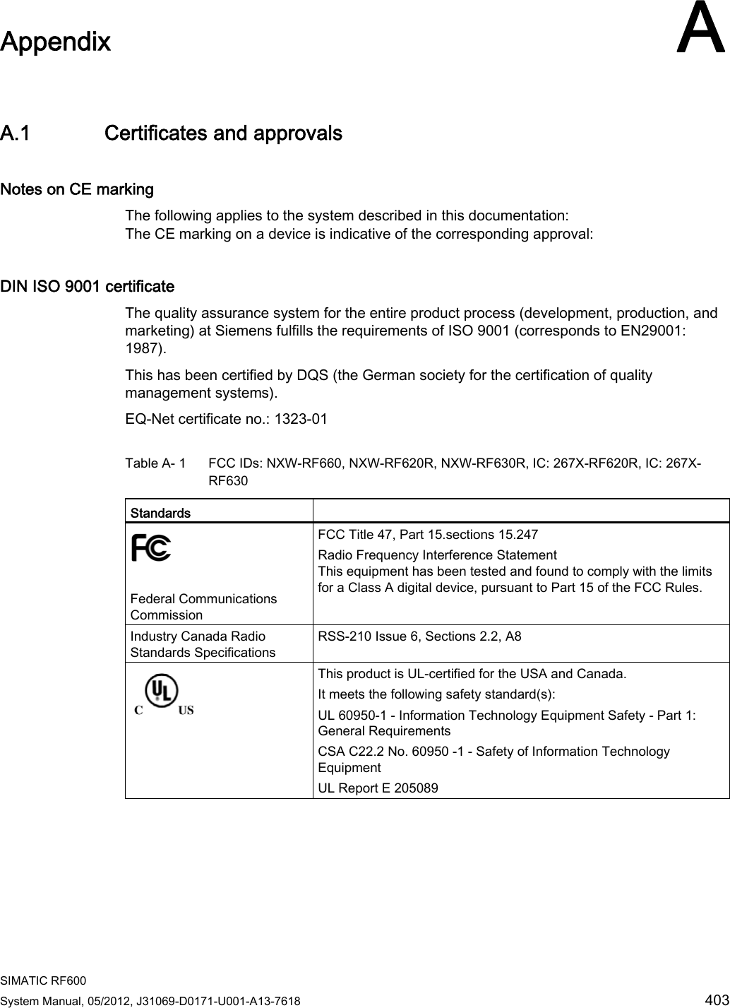
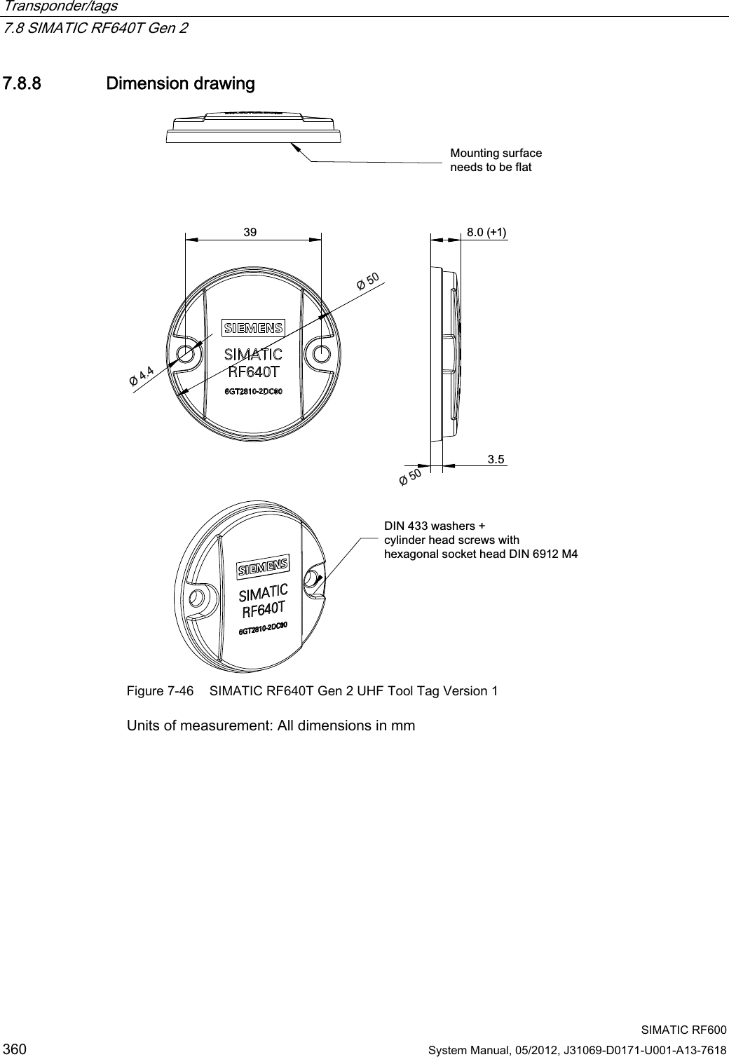
![Transponder/tags 7.9 SIMATIC RF680T SIMATIC RF600 System Manual, 05/2012, J31069-D0171-U001-A13-7618 367 7.9.3.4 Reading range when mounted on plane metallic carrier plates The transponder generally has linear polarization. The polarization axis runs as shown in the diagram below. If the transponder is centrally mounted on a plane metal plate, which may either be almost square or circular, it can be aligned in any direction if the transmitting and receiving antennas operate with circular polarization (such as RF660A and RF620R). 3RODUL]DWLRQD[LV6TXDUH0HWDOFDUULHU&LUFXODUPHWDOFDUULHUSODWHr Figure 7-51 Optimum positioning of the transponder on a (square or circular) metallic carrier plate Table 7- 28 Reading range with metallic, plane carriers with spacer Carrier plate material Reading range Europe Reading range USA Metal plate 150 x 150 mm Typ. 4 m Typ. 4 m On rectangular carrier plates, the reading distance depends on the mounting orientation of the transponder A 90° rotation of the transponder about the axis of symmetry may result in greater reading distances 7.9.3.5 Influence of conducting walls on the reading range If there are conducting walls or restrictions in the vicinity that shade the radio field, a distance of approx. 10 cm is recommended between the transponder and the wall. In principle, walls have least influence if the polarization axis is orthogonal to the conducting wall.](https://usermanual.wiki/Siemens/RF600R.User-manual-05/User-Guide-1716294-Page-9.png)
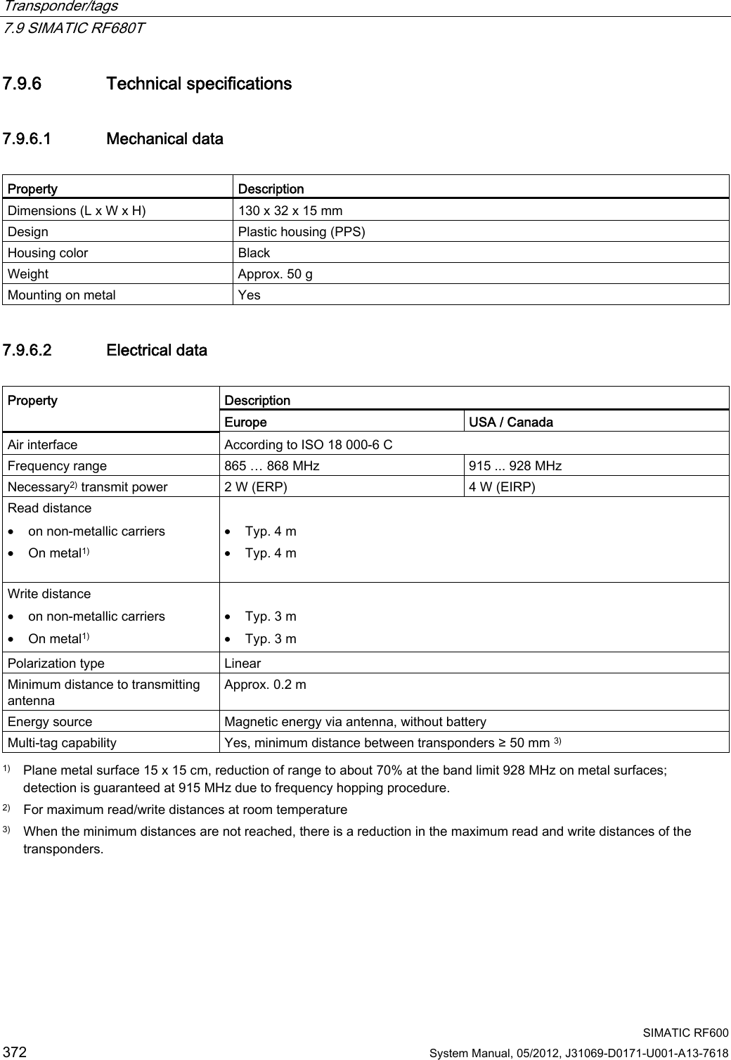
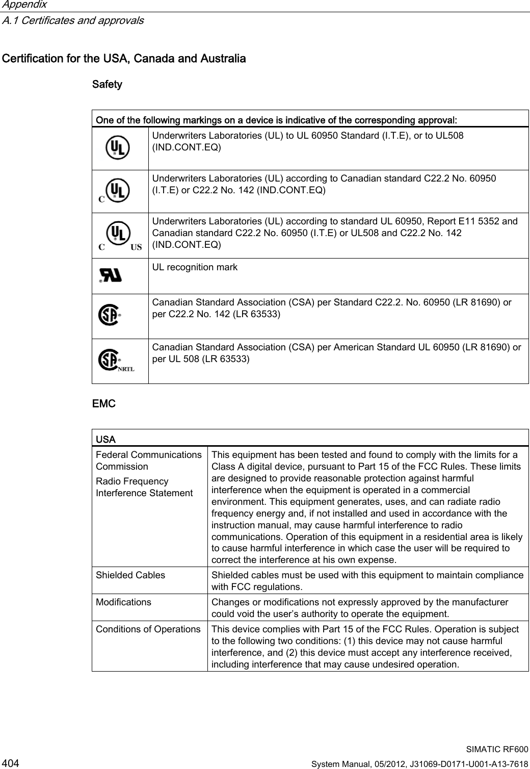
![Transponder/tags 7.9 SIMATIC RF680T SIMATIC RF600 368 System Manual, 05/2012, J31069-D0171-U001-A13-7618 Reading range: One conducting wall Influence on reading range when positioned orthogonally to the conducting wall G&RQGXFWLQJZDOO3RODUL]DWLRQD[LV Top view Distance d 20 mm 50 mm 100 mm Approx. 100% Approx. 100% Approx. 100% Wall height 20 mm Approx. 100% Approx. 100% Approx. 100% Wall height 50 mm Reading range Approx. 80% Approx. 100% Approx. 100% Wall height 100 mm Influence on reading range when positioned parallel to the conducting wall G&RQGXFWLQJZDOO3RODUL]DWLRQD[LV Top view Distance d 20 mm 50 mm 100 mm Approx. 50% Approx. 70% Approx. 90% Wall height 20 mm Approx. 40% Approx. 70% Approx. 90% Wall height 50 mm Reading range Approx. 30% Approx. 50% Approx. 90% Wall height 100 mm](https://usermanual.wiki/Siemens/RF600R.User-manual-05/User-Guide-1716294-Page-10.png)
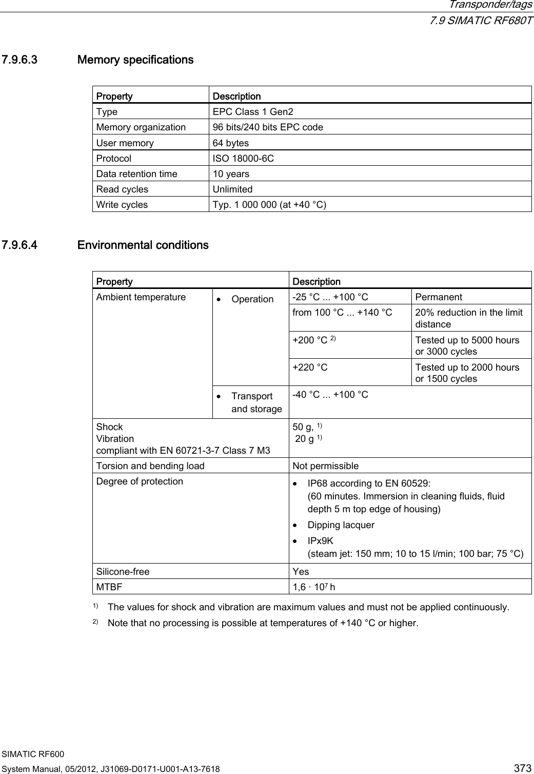
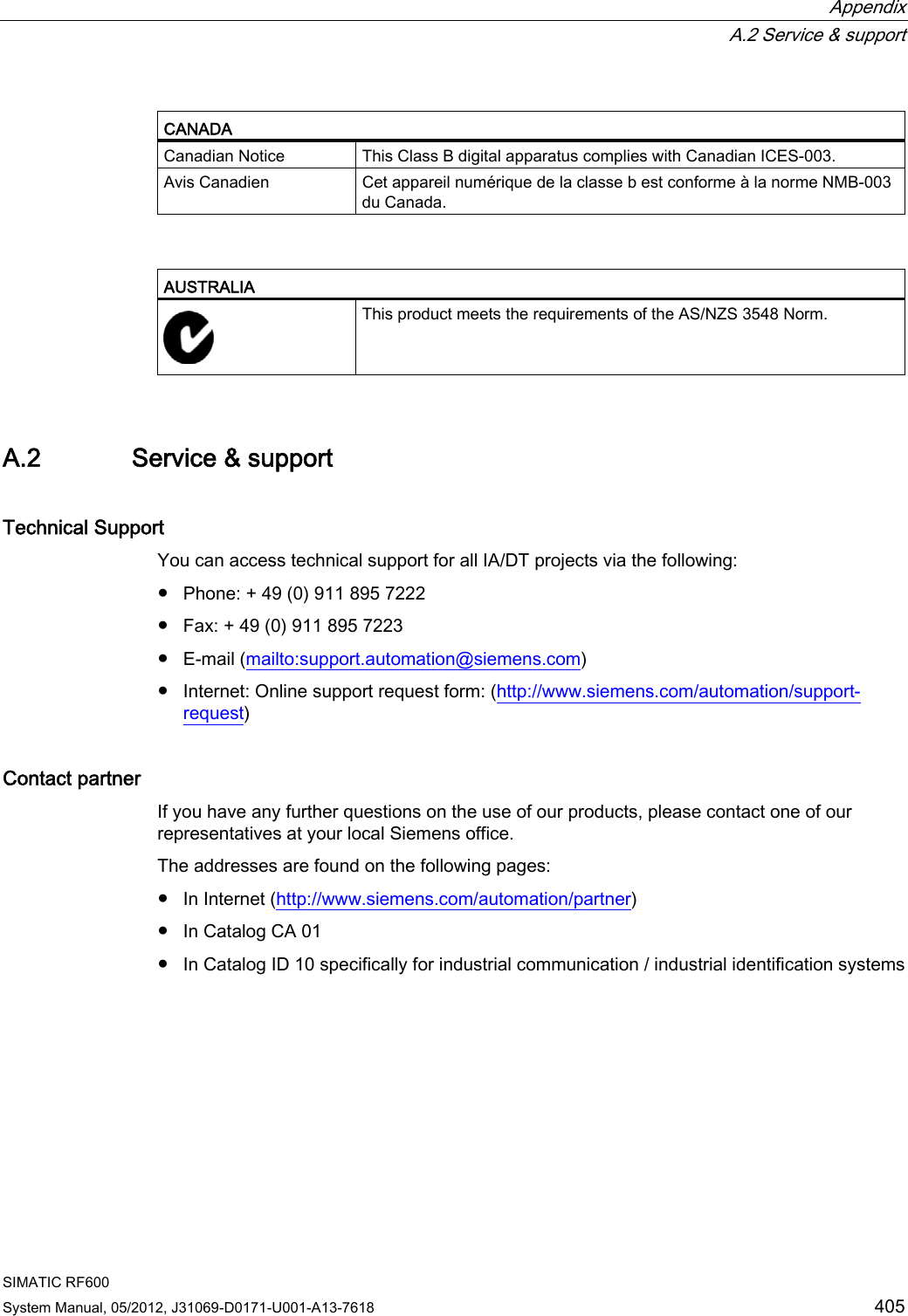
![Transponder/tags 7.9 SIMATIC RF680T SIMATIC RF600 System Manual, 05/2012, J31069-D0171-U001-A13-7618 369 Reading range: Two conducting walls Influence on reading range when positioned against two conducting walls GG&RQGXFWLQJZDOO&RQGXFWLQJZDOO3RODUL]DWLRQD[LV G&RQGXFWLQJZDOO&RQGXFWLQJZDOO:DOOKHLJKW Side view Distance d 20 mm 50 mm 100 mm Approx. 50% Approx. 70% Approx. 90% Wall height 20 mm Approx. 30% Approx. 60% Approx. 90% Wall height 50 mm Reading range Approx. 25% Approx. 50% Approx. 90% Wall height 100 mm The values specified in the tables above are reference values.](https://usermanual.wiki/Siemens/RF600R.User-manual-05/User-Guide-1716294-Page-11.png)