Siemens RF600R RFID UHF Reader User Manual SIMATIC RF600
Siemens AG RFID UHF Reader SIMATIC RF600
UserManual.wiki
>
Siemens
>
RF600R User Manual
>
User manual 03
Contents
1.
User manual 01
2.
User manual 02
3.
User manual 03
4.
User manual 04
5.
User manual 05
User manual 03
Navigation menu
Upload a User Manual
Namespaces
Wiki Guide
HTML
PDF
Info
Views
User Manual
Discussion / Help
Navigation
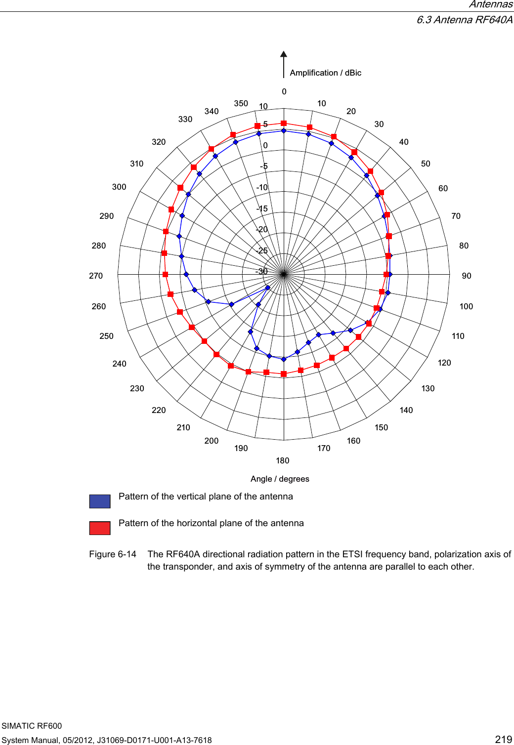
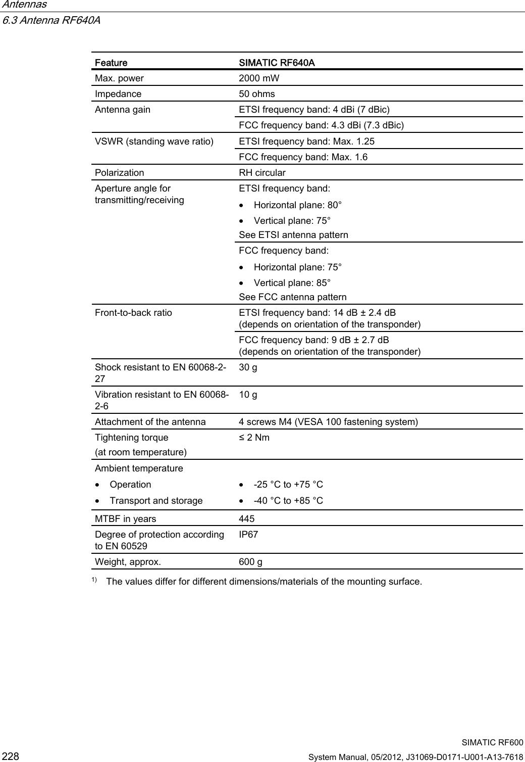
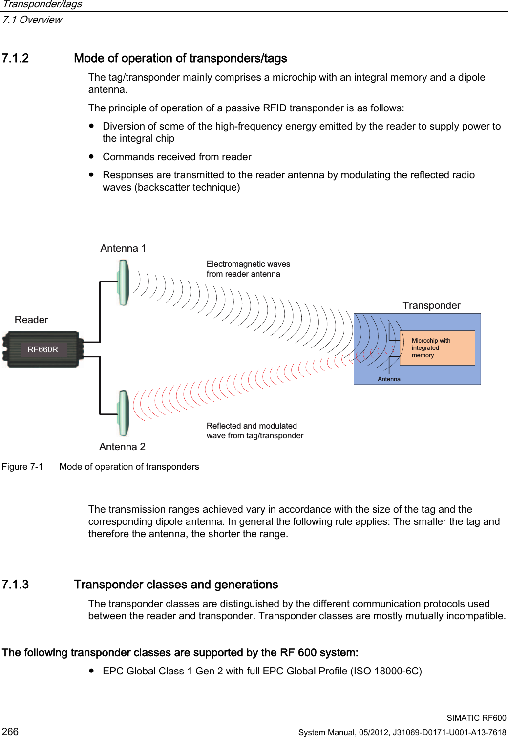
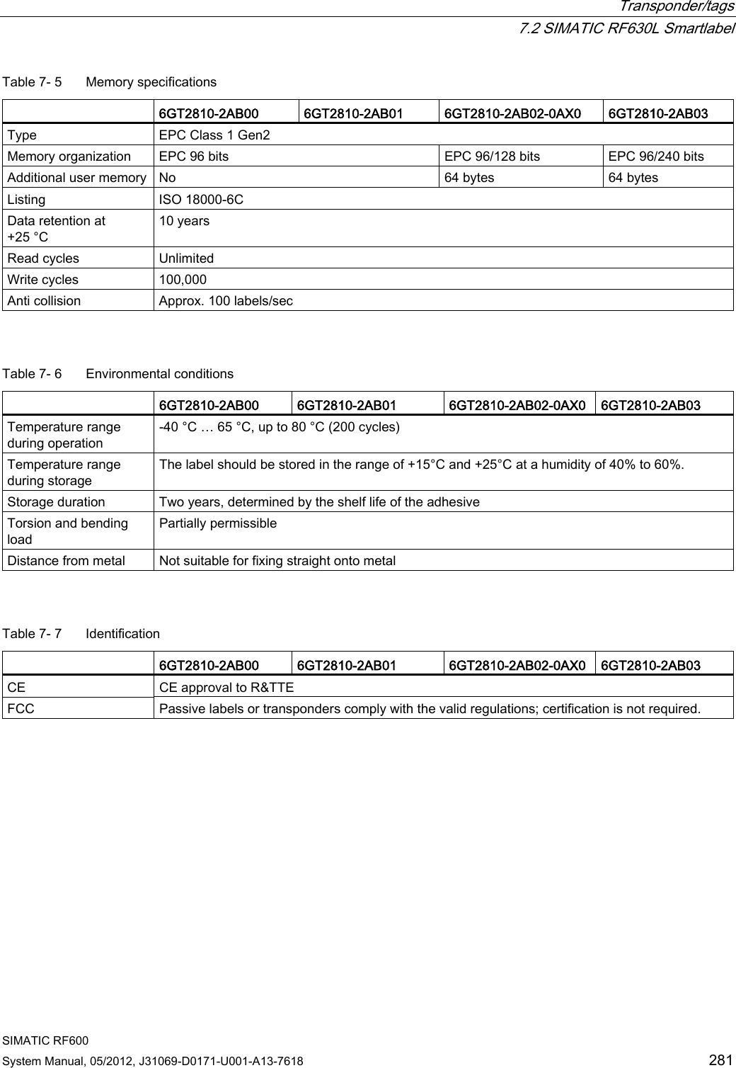
![Antennas 6.3 Antenna RF640A SIMATIC RF600 System Manual, 05/2012, J31069-D0171-U001-A13-7618 227 The dBr values correspond to the difference between the maximum dBi/dBic value and a second dBi/dBic value. Deviation from maximum antenna gain [dBr] Read/write range [%] 0 100 -3 70 -6 50 -9 35 -12 25 -15 18 -18 13 Example As can be seen in Directional radiation patterns in the ETSI frequency band (Page 218), the maximum antenna gain in the vertical plane is 3.45 dBi (6.45 dBic). In this plane, and with the polarization axis of the transponder parallel to the axis of symmetry of the antenna, the antenna gain drops to about 0.5 dBic at +50° or 310°. Therefore the dBr value is -6. The antenna range is only 50% of the maximum range at + 50° or 310° from the Z axis within the vertical plane (see values shown in blue in the directional radiation pattern: Characteristic of the vertical plane of the antenna (Page 218) and the associated representation of the reference system (Page 217)). 6.3.8 Technical data Table 6- 12 General technical specifications RF640A Feature SIMATIC RF640A Dimensions (L x W x H) 185 x 185 x 45 mm Color Pastel turquoise PA 12 (polyamide 12) Material Silicone-free Frequency range 865 to 928 MHz Plug connection 30 cm antenna connection coaxial cable with RTNC coupling, fixed connection to antenna An antenna cable is required for connection to the reader, e.g.: 6GT2815-0BH30 Max. radiated power according to ETSI • RF620R, RF630R: < 610 mW ERP • RF640R, RF670R: ≤1300 mW ERP Max. radiated power according to CMIIT • RF620R, RF630R: ≤650 mW ERP • RF640R, RF670R: ≤ 1300 mW ERP Max. radiated power according to FCC • RF620R, RF630R: ≤ 1070 mW EIRP • RF640R, RF670R: ≤2700 mW EIRP](https://usermanual.wiki/Siemens/RF600R.User-manual-03/User-Guide-1716292-Page-9.png)
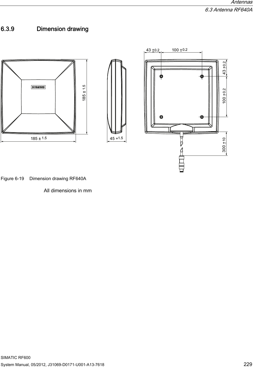
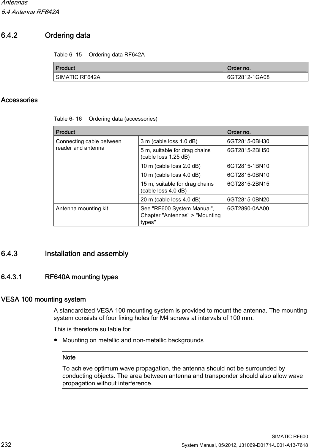
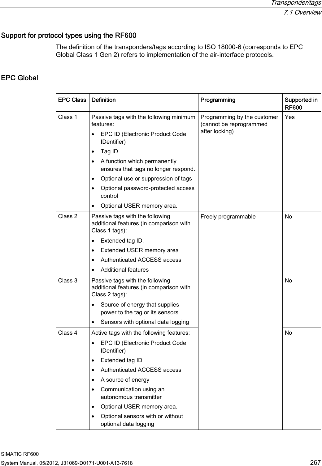
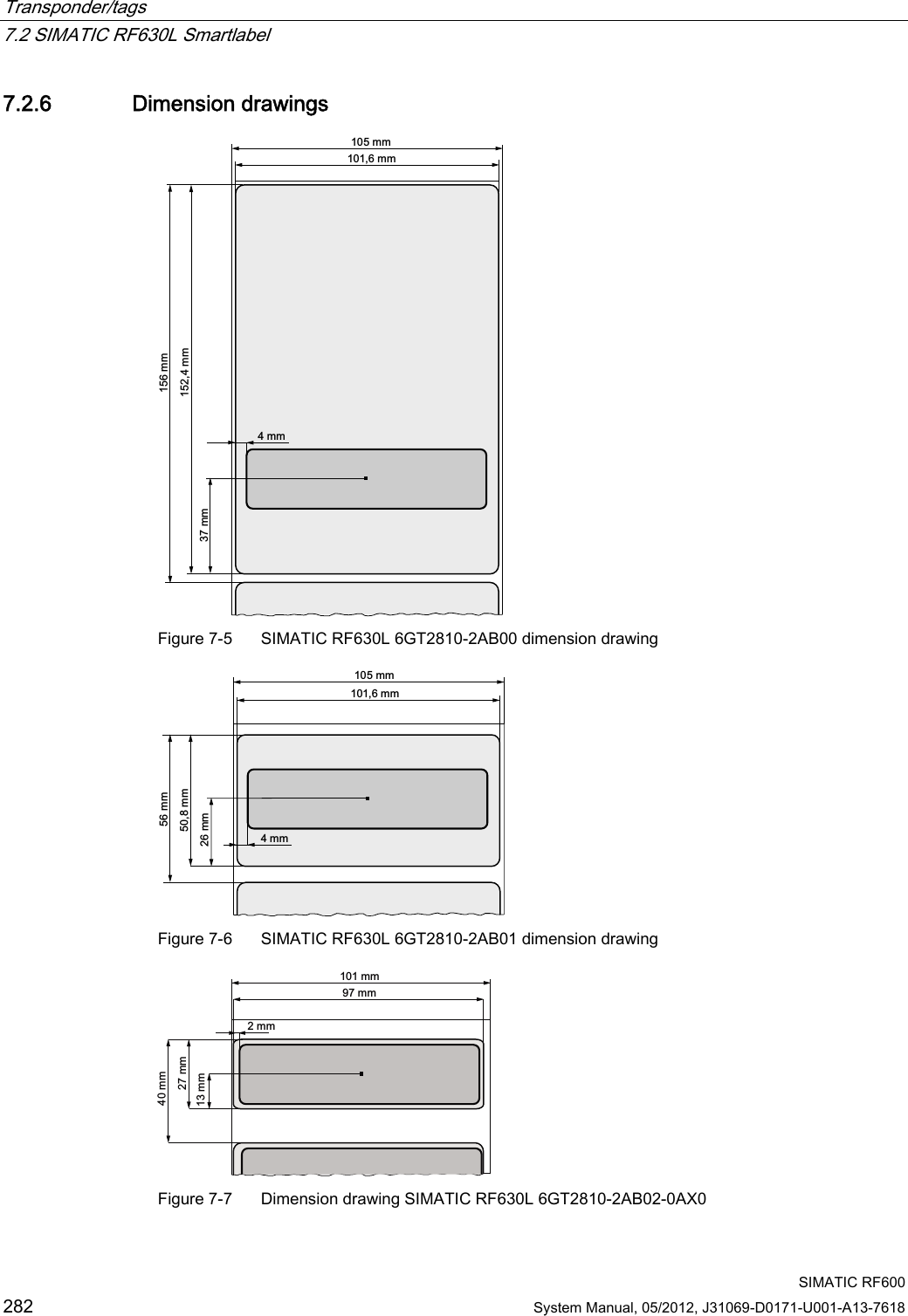
![Antennas 6.4 Antenna RF642A SIMATIC RF600 234 System Manual, 05/2012, J31069-D0171-U001-A13-7618 6.4.4.1 Bending radii and bending cycles of the cable Cable designation Order No. Length [m] Cable loss [dB] Bending radius [mm] Bending cycle RF642A antenna connection Fixed connection to antenna 0,3 - - 1 Mal Antenna cable 6GT2815-0BH30 3 1 51 1 Mal Antenna cable (suitable for drag chains) 6GT2815-2BH50 5 1,25 48 1) Antenna cable 6GT2815-1BN10 10 2 77 1 Mal Antenna cable 6GT2815-0BN10 10 4 51 1 Mal Antenna cable (suitable for drag chains) 6GT2815-0BN20 15 4 24 1) Antenna cable 6GT2815-0BN20 20 4 77 1 Mal 1) With cables suitable for drag chains, 3 million bending cycles at a bending radius of 6.5 m and bending through ± 180 ° are permitted.](https://usermanual.wiki/Siemens/RF600R.User-manual-03/User-Guide-1716292-Page-16.png)
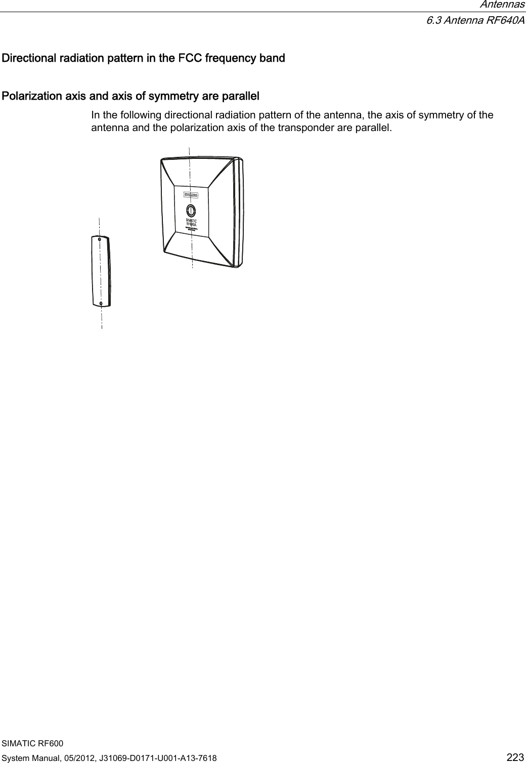
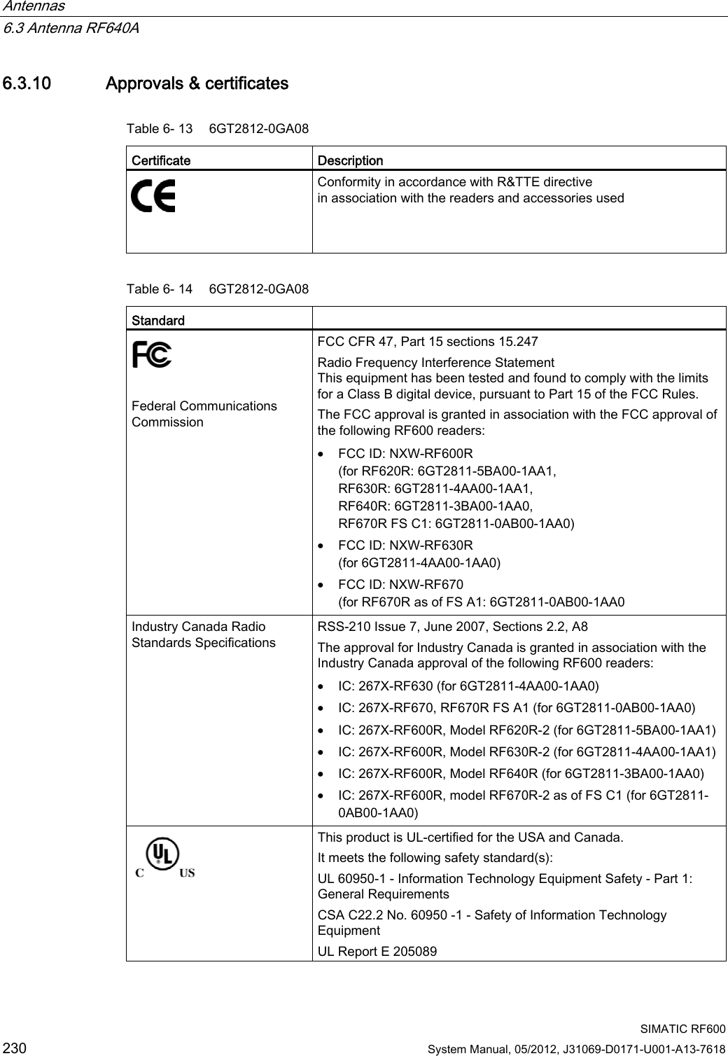
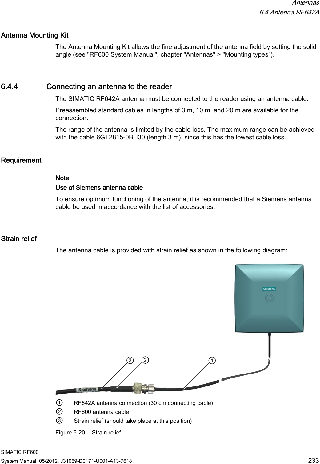
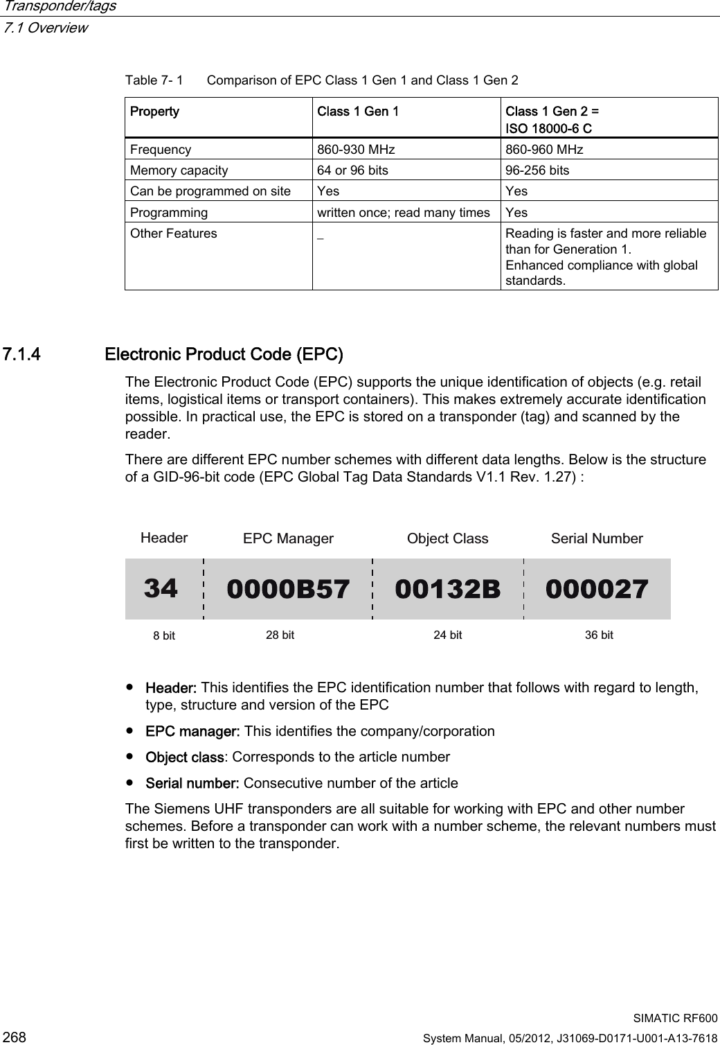
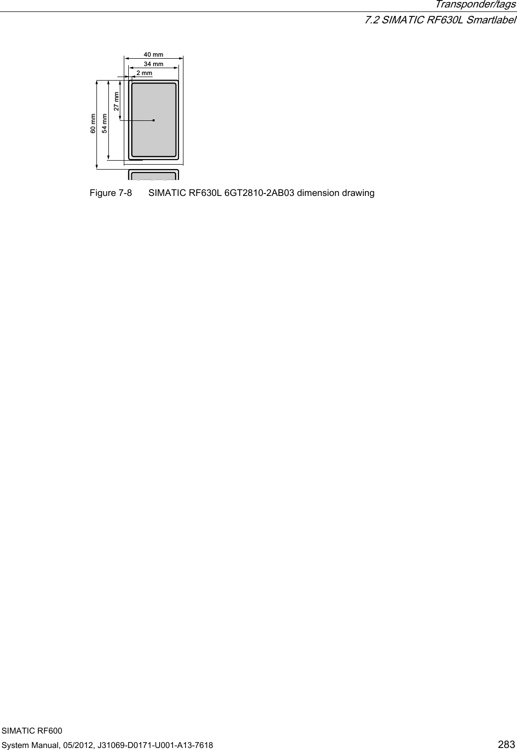
![Antennas 6.4 Antenna RF642A SIMATIC RF600 System Manual, 05/2012, J31069-D0171-U001-A13-7618 235 6.4.5 Alignment of transponders to the antenna Polarization axis Since the RF642A antenna has linear polarization, it is necessary to consider the alignment of the transponders with regard to the polarization axis of the antenna. The polarization axes of antenna and transponder must always be parallel. The symbol on the antenna indicates the polarization axis. 3RODUL]DWLRQD[LV Figure 6-21 Polarization axis](https://usermanual.wiki/Siemens/RF600R.User-manual-03/User-Guide-1716292-Page-17.png)
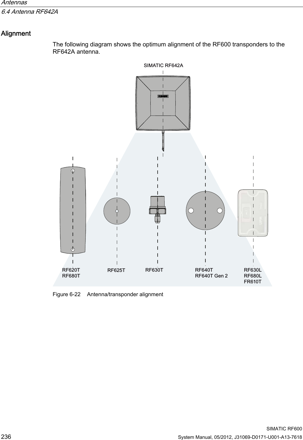
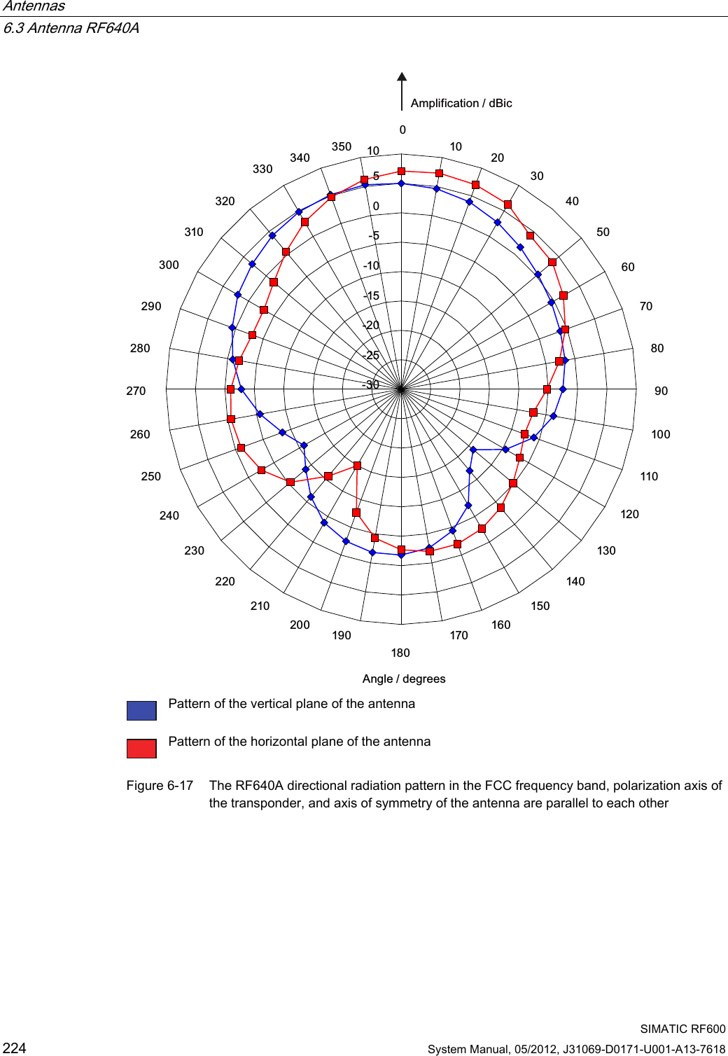
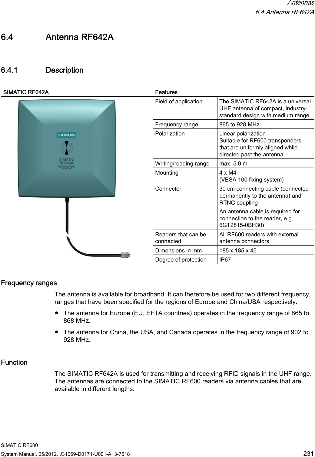
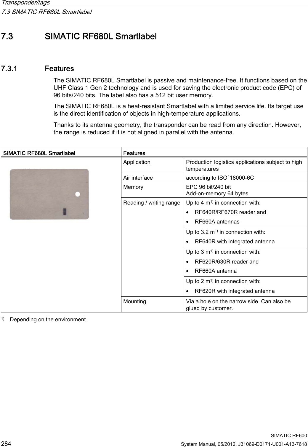
![Antennas 6.4 Antenna RF642A SIMATIC RF600 System Manual, 05/2012, J31069-D0171-U001-A13-7618 237 Angle deviation diagram for alignment The following diagram shows the dependence of the following factors. ● Alignment angle of transponder to antenna ● Maximum range of antenna 6,0$7,&5)$$QJOHGHYLDWLRQRIWKHSRODUL]DWLRQD[HVRIDQWHQQDDQGWDJ>GHJUHHV@0D[UDQJH>@r r r r r r r r rr r r r r r rr r Figure 6-23 Angle deviation diagram for alignment](https://usermanual.wiki/Siemens/RF600R.User-manual-03/User-Guide-1716292-Page-19.png)
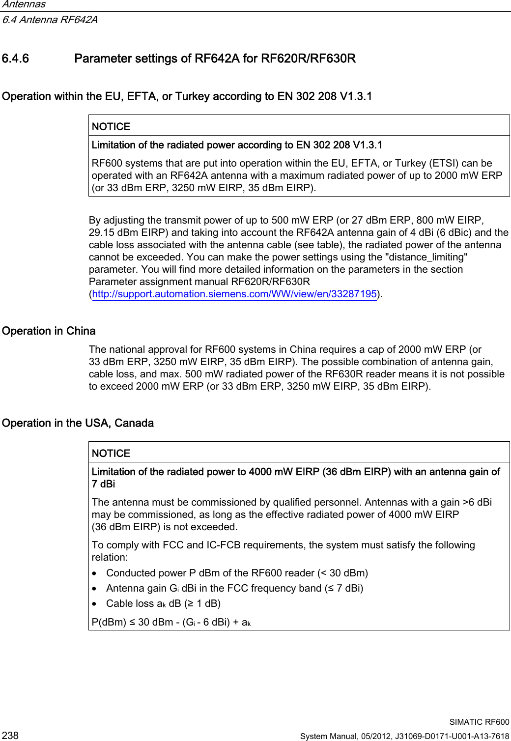
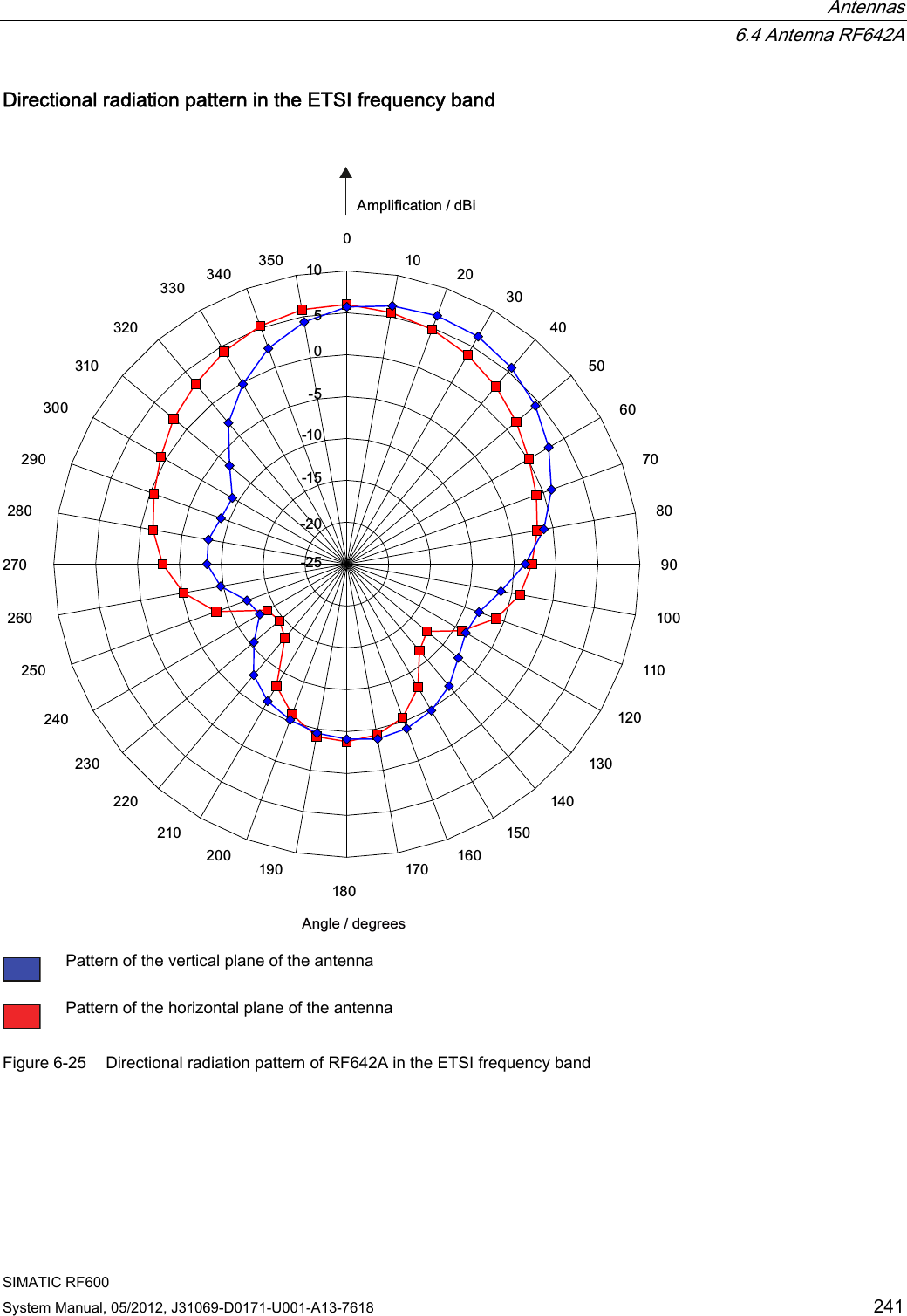
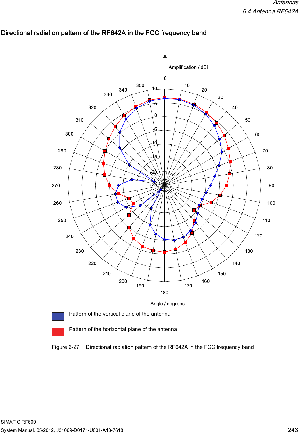
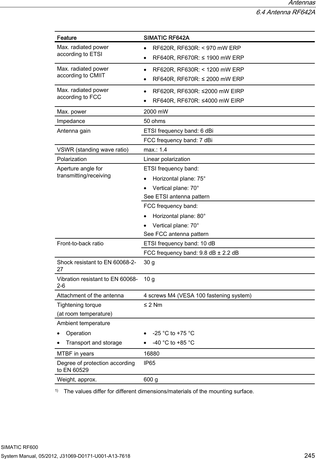
![Antennas 6.4 Antenna RF642A SIMATIC RF600 244 System Manual, 05/2012, J31069-D0171-U001-A13-7618 6.4.8.3 Interpretation of directional radiation patterns The following overview table will help you with the interpretation of directional radiation patterns. The table shows which dBi values correspond to which read/write ranges (in %): You can read the radiated power depending on the reference angle from the directional radiation patterns, and thus obtain information on the read/write range with this reference angle with regard to a transponder. The dBr values correspond to the difference between the maximum dBi value and a second dBi value. Deviation from maximum antenna gain [dBr] Read/write range [%] 0 100 -3 70 -6 50 -9 35 -12 25 -15 18 -18 13 Example As can be seen in Directional radiation pattern in the ETSI frequency band (Page 241), the maximum antenna gain in the horizontal plane is 6 dBi. In this plane and with the parallel polarization axis at +70° or 300°, the antenna gain dropped to about 0 dBi. Therefore the dBr value is 6. The antenna range is only 70° of the maximum range at + 50° or +300° from the Z axis within the horizontal plane (see values shown in red in the directional radiation pattern: Characteristic of the vertical plane of the antenna and the associated representation of the reference system). 6.4.9 Technical data Table 6- 17 General technical specifications RF642A Feature SIMATIC RF642A Dimensions (L x W x H) 185 x 185 x 45 mm Color Pastel turquoise PA 12 (polyamide 12) Material Silicone-free Frequency range 865 to 928 MHz Plug connection 30 cm coaxial cable with RTNC coupling An antenna cable is required for connection to the reader, e.g.: 6GT2815-0BH30](https://usermanual.wiki/Siemens/RF600R.User-manual-03/User-Guide-1716292-Page-26.png)
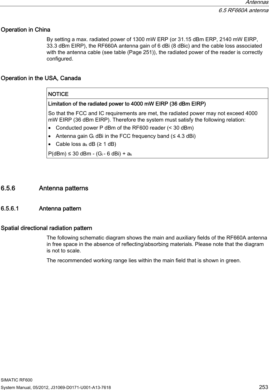
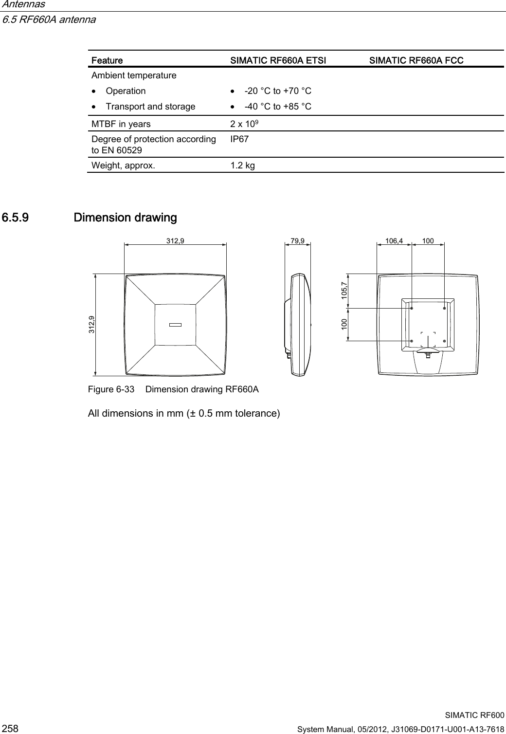
![Antennas 6.5 RF660A antenna SIMATIC RF600 System Manual, 05/2012, J31069-D0171-U001-A13-7618 251 Connecting RF660A to RF630R Preassembled standard cables in lengths of 3 m, 10 m and 20 m are available for connection. The cable between antenna and reader can be up to 20 m in length. When one antenna is used, it is recommended that the remaining antenna connection is sealed using the supplied protective cap. 6.5.3.1 Bending radii and bending cycles of the cable Cable designation Order No. Length [m] Cable loss [dB] Bending radius [mm] Bending cycle Antenna cable 6GT2815-0BH30 3 1 51 1 Mal Antenna cable (suitable for drag chains) 6GT2815-2BH50 5 1,25 1) 1) Antenna cable 6GT2815-1BN10 10 2 77 1 Mal Antenna cable 6GT2815-0BN10 10 4 51 1 Mal Antenna cable (suitable for drag chains) 6GT2815-0BN20 15 4 1) 1) Antenna cable 6GT2815-0BN20 20 4 77 1 Mal 1) With cables suitable for drag chains, 3 million bending cycles at a bending radius of 6.5 mm and bending through ± 180° are permitted. 6.5.4 Parameter settings of RF660A for RF620R/RF630R Operation within the EU, EFTA, or Turkey NOTICE Limitation of the radiated power according to EN 302 208 V1.3.1 RF600 systems that are put into operation within the EU, EFTA, or Turkey (ETSI) can be operated with an RF660A antenna with a maximum radiated power of up to 2000 mW ERP (or 33 dBm ERP, 3250 mW EIRP, 35 dBm EIRP).](https://usermanual.wiki/Siemens/RF600R.User-manual-03/User-Guide-1716292-Page-33.png)
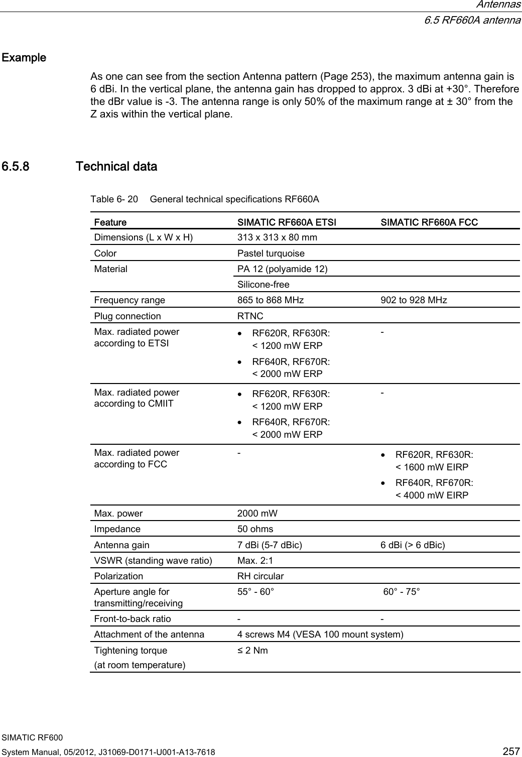
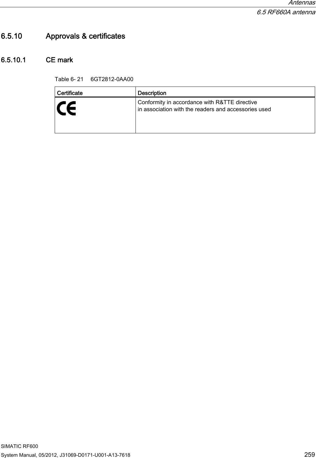
![Antennas 6.5 RF660A antenna SIMATIC RF600 256 System Manual, 05/2012, J31069-D0171-U001-A13-7618 3KL r G%G%G%*DLQLQG%$QJOHLQGHJUHHV Figure 6-32 Directional radiation pattern of the antenna (at 915 MHz, horizontal alignment) 6.5.7 Interpretation of directional radiation patterns The following overview table will help you with the interpretation of directional radiation patterns. The table shows which dBi values correspond to which read/write ranges (in %): You can read the radiated power depending on the reference angle from the directional radiation patterns, and thus obtain information on the read/write range with this reference angle with regard to a transponder. The dBr values correspond to the difference between the maximum dBi value and a second dBi value. Deviation from maximum antenna gain [dBr] Read/write range [%] 0 100 -3 70 -6 50 -9 35 -12 25 -15 18 -18 13](https://usermanual.wiki/Siemens/RF600R.User-manual-03/User-Guide-1716292-Page-38.png)
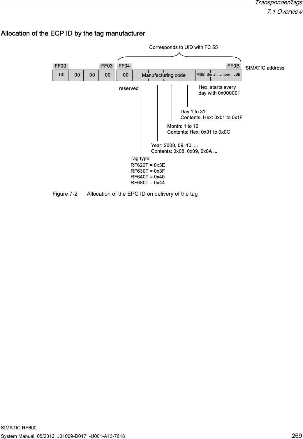
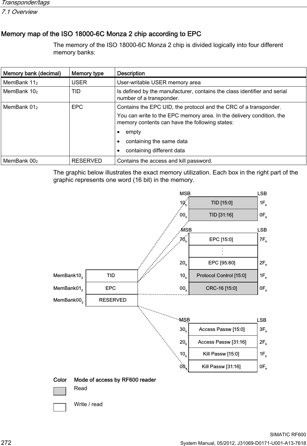
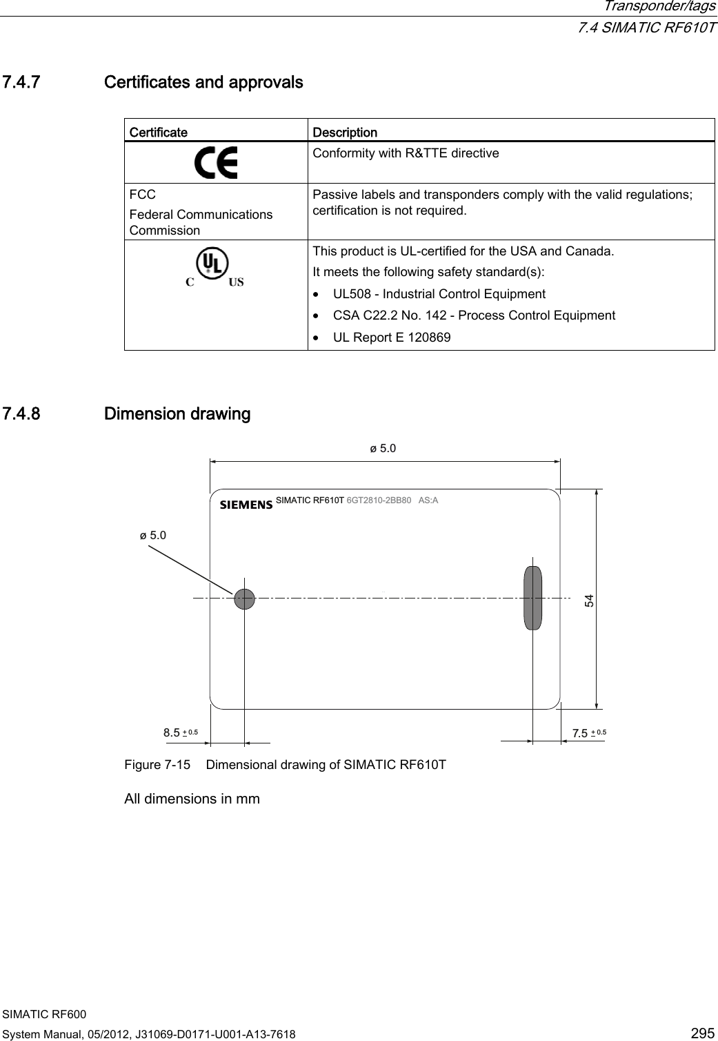
![Transponder/tags 7.1 Overview SIMATIC RF600 270 System Manual, 05/2012, J31069-D0171-U001-A13-7618 7.1.5 SIMATIC memory configuration of the RF600 transponders and labels SIMATIC memory configuration The following graphic shows the structure of the virtual SIMATIC memory for the RF620R/RF630R reader and explains the function of the individual memory areas. The SIMATIC memory configuration is based on the 4 memory banks, as they are defined in EPC Global. 7KH86(5PHPRU\DUHDDOZD\VEHJLQVDWDGGUHVVDQGHQGVZLWKWKHKLJKHVWDGGUHVVRIWKHWDJ7KHPD[LPXPVL]HRIWKH86(5PHPRU\DUHDLVE\WHV7KH(3&PHPRU\DUHDDOZD\VVWDUWVDWWKHDGGUHVV))7KHPD[LPXPVL]HRIWKH(3&PHPRU\DUHDLVE\WHV7KH(3&PHPRU\DUHDFRQWDLQVWKH(3&,'DQGWKHSURWRFROFRQWUROZRUG$FFHVVWRWKH&5&PHPRU\LVQRWSRVVLEOH))(OHQJWKE\WHV 3&3URWRFRO&RQWURO:RUG2SWLRQDOPHPRU\DUHDSDVVZRUGVRIWKHWUDQVSRQGHUವ )) .,//SDVVZRUGವ )) $&&(66SDVVZRUG2SWLRQDOPHPRU\DUHD7KH7,'PHPRU\DUHDFRQWDLQVPDQXIDFWXUHUVSHFLILFGDWD5HDGRQO\VL]HFDQYDU\DFFRUGLQJWRWKHPDQXIDFWXUHU7,'5(6(59('(3&86(50HP%DQN0HP%DQNKH[))KH[)))KH[))KH[))%)KH[))&KH[)))KH[0HP%DQN0HP%DQN)()KH[ Figure 7-3 SIMATIC memory areas of the RF600 transponders](https://usermanual.wiki/Siemens/RF600R.User-manual-03/User-Guide-1716292-Page-52.png)
![Transponder/tags 7.1 Overview SIMATIC RF600 System Manual, 05/2012, J31069-D0171-U001-A13-7618 271 Special memory configuration of the RF600 transponders and labels Tags Chip type User [hex] EPC TID RESERVED (passwords) Special Range Access KILL-PW Lock function RF630L (-2AB00, -2AB01) Impinj Monza 2 00 - 3F FF00-FF0B(96 bits = FF00-FF0F)read/ write FFC0-FFC7 FF80-FF87 Yes Yes RF630L (-2AB02) Impinj Monza 4QT 00 - 3F FF00-FF0B(128 bits = FF00-FF0F)read/ write FFC0-FFC9 FF80-FF87 Yes Yes RF630L (-2AB03) NXP G2XM 00 - 3F FF00-FF0B(240 bits = FF00-FF0F)read/ write FFC0-FFC7 FF80-FF87 Yes Yes RF680L NXP G2XM 00 - 3F FF00-FF0B(240 bits = FF00-FF0F)read/ write FFC0-FFC7 FF80-FF87 Yes Yes RF610T NXP G2XM 00 - 3F FF00-FF0B(240 bits = FF00-FF0F)read/ write FFC0-FFC7 FF80-FF87 LOCKED Yes RF620T Impinj Monza 4QT 00 - 3F FF00-FF0B(128 bits = FF00-FF0F)read/ write FFC0-FFC9 FF80-FF87 LOCKED Yes RF625T Impinj Monza 4QT 00 - 3F FF00-FF0B(128 bits = FF00-FF0F)read/ write FFC0-FFC9 FF80-FF87 LOCKED Yes RF630T NXP G2XM 00 - 3F FF00-FF0B(240 bits = FF00-FF0F)read/ write FFC0-FFC7 FF80-FF87 LOCKED Yes RF640T NXP G2XM 00 - 3F FF00-FF0B(240 bits = FF00-FF0F)read/ write FFC0-FFC7 FF80-FF87 LOCKED Yes RF680T NXP G2XM 00 - 3F FF00-FF0B(240 bits = FF00-FF0F)read/ write FFC0-FFC7 FF80-FF87 LOCKED Yes Note Default EPC ID When an RF610T-RF680T transponder is supplied, a 12 byte long identifier is assigned by the manufacturer as the EPC ID according to a number scheme (see "Assignment of the ECP ID by the manufacturer").](https://usermanual.wiki/Siemens/RF600R.User-manual-03/User-Guide-1716292-Page-53.png)

![Transponder/tags 7.5 SIMATIC RF620T SIMATIC RF600 298 System Manual, 05/2012, J31069-D0171-U001-A13-7618 Rotation about the polarization axis 3RODUL]DWLRQD[LV Figure 7-16 Rotation of the transponder about the polarization axis Generally the range does not change when the transponder without carrier material is rotated about the polarization axis.](https://usermanual.wiki/Siemens/RF600R.User-manual-03/User-Guide-1716292-Page-80.png)
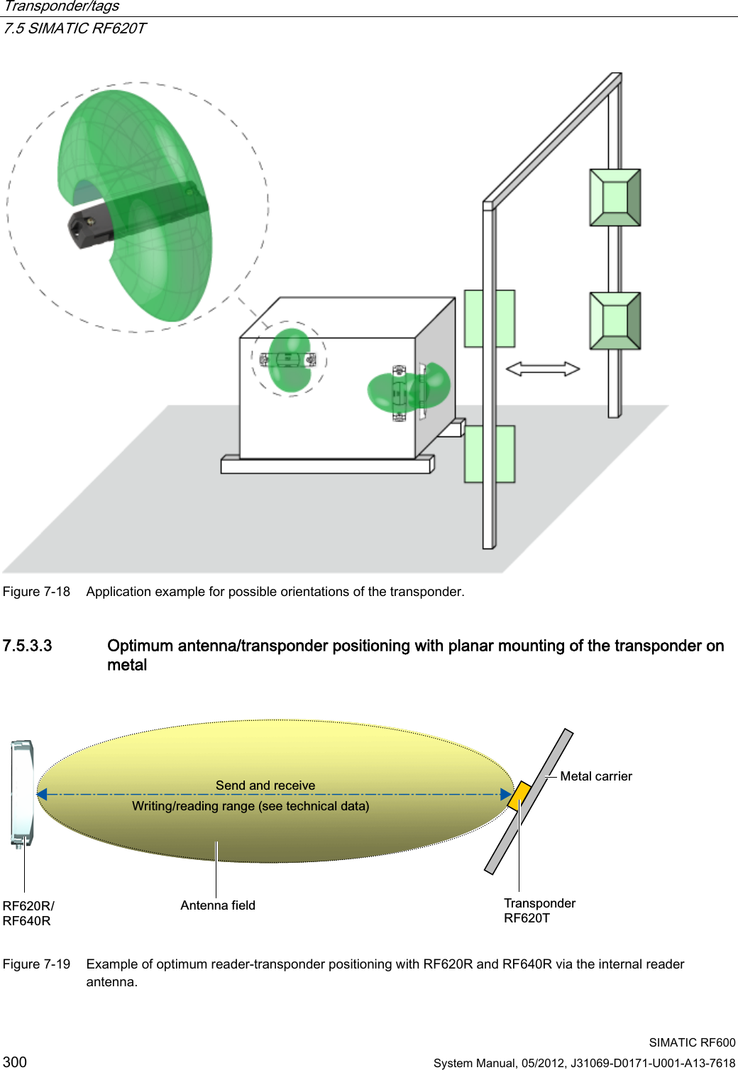
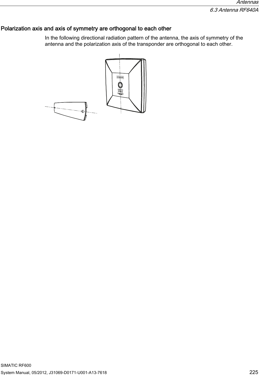
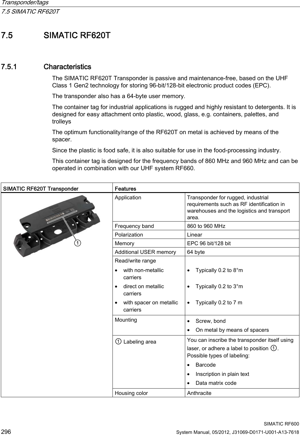
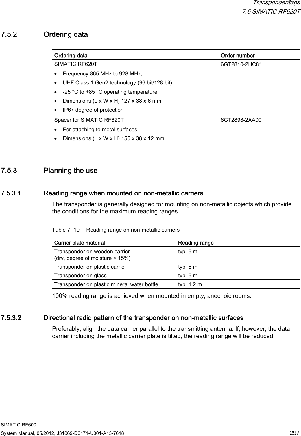
![Transponder/tags 7.5 SIMATIC RF620T SIMATIC RF600 System Manual, 05/2012, J31069-D0171-U001-A13-7618 301 7.5.3.4 Reading range when mounted on flat metallic carrier plates The transponder generally has linear polarization. The polarization axis runs as shown in the diagram below. If the tag is centrically mounted on a flat metal plate, which may either be almost square or circular, it can be aligned in any direction since the transmitting and receiving RF660A antennas operate with circular polarization. 3RODUL]DWLRQD[LV6TXDUHPHWDOVXSSRUW&LUFXODUPHWDOFDUULHUSODWHr Figure 7-20 Optimum positioning of the transponder on a (square or circular) metal carrier plate Table 7- 11 Reading range with metallic, plane carriers without spacer Carrier plate material Reading range Metal plate at least 300 x 300 mm Typ. 3 m Table 7- 12 Reading range with metallic, plane carriers with spacer Carrier plate material Reading range Metal plate at least 300 x 300 mm Typ. 7 m The use of spacers on metallic surfaces is therefore recommended. On rectangular carrier plates, the reading distance depends on the mounting orientation of the transponder A 90° rotation of the transponder about the axis of symmetry may result in greater reading distances 7.5.3.5 Influence of conducting walls on the reading range If there are conducting walls or restrictions in the vicinity that could shade the radio field, a distance of approx. 10 cm is recommended between the transponder and the wall In principle, walls have least influence if the polarization axis is orthogonal to the conducting wall. A spacer must be used in any case.](https://usermanual.wiki/Siemens/RF600R.User-manual-03/User-Guide-1716292-Page-83.png)
![Transponder/tags 7.5 SIMATIC RF620T SIMATIC RF600 302 System Manual, 05/2012, J31069-D0171-U001-A13-7618 Reading range: One conducting wall Dependence of the reading distance when positioned orthogonally to the conducting wall G&RQGXFWLQJZDOO3RODUL]DWLRQD[LV Top view Distance d 20 mm 50 mm 100 mm Approx. 100% Approx. 100% Approx. 100% Wall height 20 mm Approx. 100% Approx. 100% Approx. 100% Wall height 50 mm Reading range Approx. 80% Approx. 100% Approx. 100% Wall height 100 mm Dependence of the reading distance when positioned parallel to the conducting wall G&RQGXFWLQJZDOO3RODUL]DWLRQD[LV Top view Distance d 20 mm 50 mm 100 mm Approx. 70 % Approx. 100% Approx. 100% Wall height 20 mm Approx. 60 % Approx. 90 % Approx. 100% Wall height 50 mm Reading range Approx. 30 % Approx. 70 % Approx. 100% Wall height 100 mm](https://usermanual.wiki/Siemens/RF600R.User-manual-03/User-Guide-1716292-Page-84.png)
![Transponder/tags 7.5 SIMATIC RF620T SIMATIC RF600 System Manual, 05/2012, J31069-D0171-U001-A13-7618 303 Reading range: Two conducting walls Influence on reading range when positioned against two conducting walls GG&RQGXFWLQJZDOO&RQGXFWLQJZDOO3RODUL]DWLRQD[LV Top view G&RQGXFWLQJZDOO&RQGXFWLQJZDOO:DOOKHLJKW Side view Distance d 20 mm 50 mm 100 mm Approx. 70 % Approx. 100% Approx. 100% Wall height 20 mm Approx. 60 % Approx. 90 % Approx. 100% Wall height 50 mm Reading range Approx. 30 % Approx. 70 % Approx. 100% Wall height 100 mm The values specified in the tables above are reference values. 7.5.3.6 Directional radio pattern of the transponder on metallic surfaces Preferably, align the data carrier parallel to the transmitting antenna. If, however, the data carrier including the metallic carrier plate is tilted, the reading range will be reduced.](https://usermanual.wiki/Siemens/RF600R.User-manual-03/User-Guide-1716292-Page-85.png)
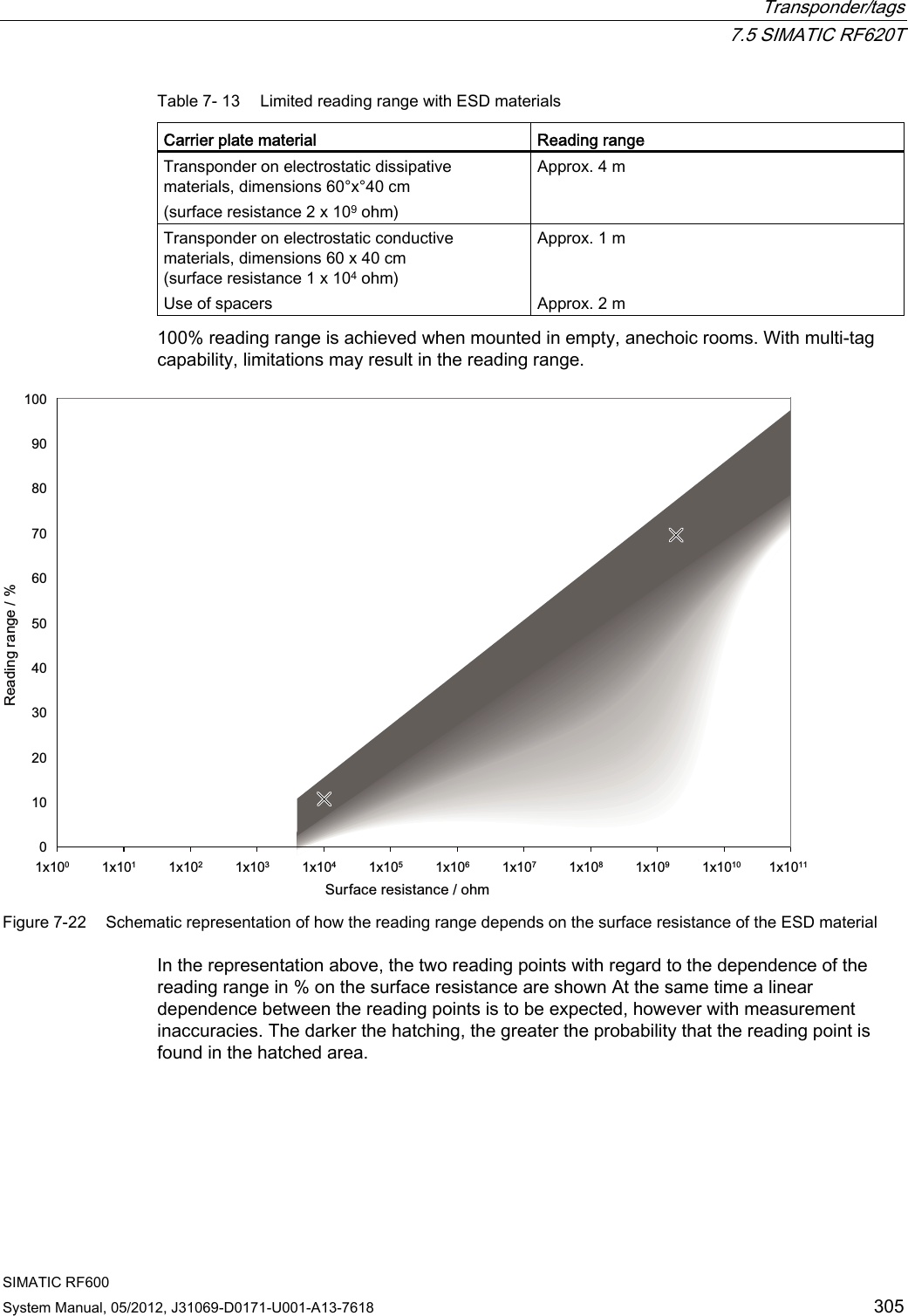
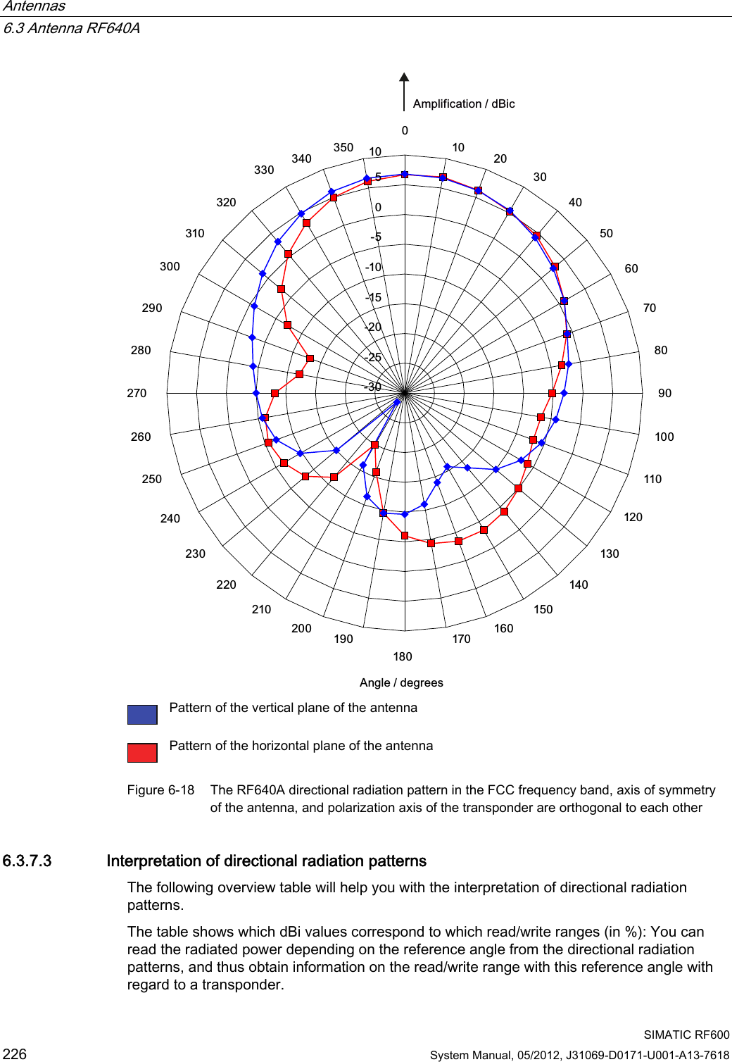
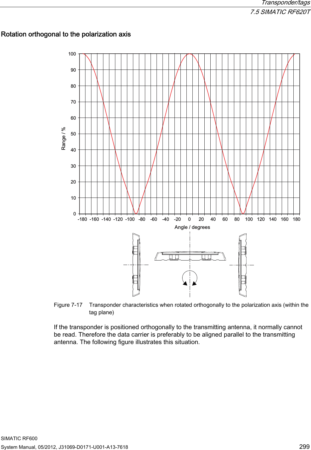
![Transponder/tags 7.5 SIMATIC RF620T SIMATIC RF600 304 System Manual, 05/2012, J31069-D0171-U001-A13-7618 Rotation about the polarization axis or orthogonal to the polarization axis rrrr 0102030405060708090100-170-150-130-110-90-70-50-30-1010305070901101301501703RODUL]DWLRQD[LV2UWKRJRQDOD[LV5HDGLQJUDQJH$QJOHGHJUHHV Figure 7-21 Characteristic of the transponder when rotated about the polarization axis or orthogonally to the polarization axis 7.5.3.7 Reading range when mounted on ESD carrier materials The transponder is generally designed for mounting on non-conductive objects which provide the conditions for the maximum reading ranges The conductive or dissipativesurface of ESD materials limits the reading range depending on the surface resistance. Generally, dissipative materials with a surface resistance of 1 x 10⁵ to 1 x 10¹¹ ohm and conductive materials with 1 x 10³ to 1 x 10⁵ ohm are available.](https://usermanual.wiki/Siemens/RF600R.User-manual-03/User-Guide-1716292-Page-86.png)